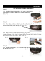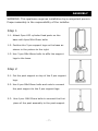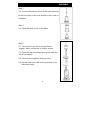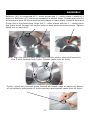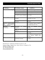
1
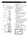
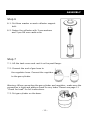
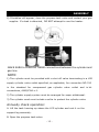
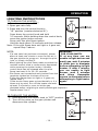
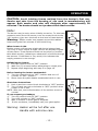
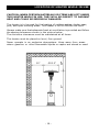
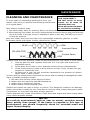
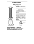
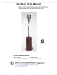
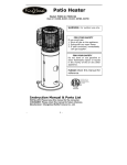
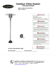
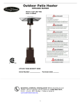
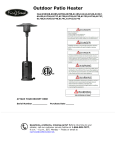
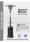
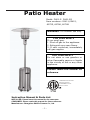
Patio Heater
Model: PH01-S PH01-SS
Item numbers: 02411,02412,
60755, 60786, 60788
WARNING: For outdoor use only.
FOR YOUR SAFETY
If you smell gas:
1. Shut off gas to the appliance.
2. Extinguish any open flame.
3. If odor continues, immediately
call gas supplier.
FOR YOUR SAFETY
Do not store or use gasoline or
other flammable vapors or liquids
in the vicinity of this or any other
appliance.
PLEASE retain this manual for
reference.
CERTIFICATE TO ANSI
STD.Z83.26-2007
CONFORM TO CSA
STD.2.37-2007
Instruction Manual & Parts List
INSTALLER: Please leave this manual for the consumer.
CONSUMER: Please retain this manual for future reference.
Manufacturer: Changzhou Wellife Furnace Co., Ltd.
-1-
Tools and parts needed for assembly
DANGER
CARBON MONOXIDE HAZARD
This appliance can produce carbon monoxide
which has no odor.
Using it in an enclosed space can kill you.
Never use this appliance in an enclosed space
such as a camper, tent, car or home.
WARNING: Improper installation, adjustment,
alteration, service or maintenance can cause injury
or property damage.
Read the installation,
operating and maintenance instructions thoroughly
before installing or servicing this equipment.
Tools needed:
●
NOT included:
Adjustable opening wrench
8’’ long
●
●
WARNING :
●
For Outdoor Use Only
LPG Cylinders to be used must be constructed and
marked in accordance with US DOT specifications.
Storage of the heater indoors is permissible only
if the gas cylinder is turned off and removed.
NOTE:
Use only 20lb LP-Gas tank with size of 18.1in
/ 46cm(Height)*12.5in / 32cm (Width).
Do not use if the environment temperature is
below 40 degrees F / 4.4 degrees C.
-2-
Open end wrench 10 &
13mm (included)
Philips screwdriver
w/ medium blade
Spray bottle of soapy
solution for leak testing
PRECAUTIONS
NOTE: PLEASE READ THE FOLLOWING SAFETY RULES
WARNING:
This heater must only be used outdoors. Using this product in an enclosed area may
cause injury, death or property damage.
Only use in a well-ventilated space. Do not use in a building, garage, or any other
enclosed area.
Read the instructions before use. This heater must be installed in accordance
with local codes or, in the absences of local codes, with the National Fuel Code, ANSI
Z223.1. If applicable, the heater, when installed, must be electrically grounded in
accordance with local codes or, in the absence of local codes, with The National
Electrical Code, ANSI/NFPA70.
Do not use the heater in an explosive atmosphere. Keep the heater away from areas
where gasoline or other flammable liquids or vapors are stored.
Prior to use, check for damaged parts such as hoses, regulators, pilot or burner .
Turn off and disconnect LPG cylinder before moving the heater.
Do not attempt to alter this heater in any manner. EXAMPLE: Using the heater without
the top canopy reflector or radiant screen.
Do not shorten the burner post assembly.
Do not use this heater in basements or below ground level. It must always be placed on
a solid and level surface.
Always ensure there is ample fresh air ventilation. For outdoor use ONLY.
Never replace or substitute the regulator with any regulator other than the factory
suggested replacement.
Do not clean the heater with cleaners that are combustible or corrosive.
Do not paint radiant screen, control panel, or top canopy reflector.
All leak tests should be done with a soapy solution. NEVER USE AN OPEN FLAME TO
CHECK FOR LEAKS.
The LPG cylinder should be turned off when the heater is not in use.
At least once a year, the unit should be inspected for the presence of spiders, spider
webs or other insects.
-3-
PRECAUTIONS
CHECK THE HEATER IMMEDIATELY IF ANY OF THE FOLLOWING
EXIST:
1. The smell of gas in conjunction with extreme yellow colored tips of the burner flames.
2. The heater does not reach temperature.
3. The burner makes a popping noise during use (a slight popping noise is normal
when the burner is extinguished after using).
Children and adults should be aware of the hazards of high surface temperature,
and should stay away to avoid burns or clothing ignition.
Young children should be carefully superv ised when they are in the area of the heater.
Clothing or other flammable material should not be hung from the heater, or placed
on or near the heater.
Any guard or other protective device removed for servicing the heater must
be replaced prior to operating the heater.
Installation and repair should be done by a qualified service person. The heater should
be inspected before use and cleaning may be required at least once a year, or as
necessary. It is imperative that the control compartment, burner and circulating
passageways of the heater are kept clean.
Keep the heater area clear of combustible materials such as gasoline and other
flammable vapors and liquids.
Do not obstruct the flow of combustion and ventilation air.
Keep the ventilation opening of the LPG cylinder enclosure free and clear of debris.
Storage of a heater indoors is permissible only if the LPG cylinder is turned
off, disconnected and removed from the heater.
Cylinders must be stored outdoors in a well-ventilated area out of the reach
of children. Disconnected cylinders must have threaded valve plugs tightly
installed, and must not be stored in a building, garage or any other enclosed
area.
-4-
ASSEMBLY
1. 3 pcs castle nuts
2. Reflector
3. 6 pcs 8mm washers for pins
support
4. 3 pcs 90mm (L) pins for
reflector support
5. Head assembly
6. 4 pcs M6x10mm bolts
7. 2 pcs Post assembly
8. Tank housing
9. Regulator
10. 6 pcs M6x30mm bolts and
6mm nuts for connection of
post support and support
legs
11. 3 pcs M8x16mm bolts for
connection of support
legs and base
12. Post support
13. 6pcs M6x12mm bolts and 6pcs
M6 screw for connection LPG
cylinder fixed parts with base,
6pcs M8x25mm bolts for
securing the cylinder
14. 3 pcs Support legs
15. Base
16. 1 pc open end wrench
(10&13mm) NOT PICTURED
17. Wheel assembly
18. Gas hose
(attached to head assembly)
17
-5-
ASSEMBLY
Step 1
ATTACHING WHEEL ASSEMBLY
1-1. Locate Wheel Assembly (17) and 2 nuts/bolts
contained in plastic bag with Wheel Assembly
(Fig. 1).
Fig. 1
Step 2
2-1. Turn Base (15) so that holes for attachment of
Wheel Assembly are facing you (Fig. 2).
Fig. 2
2-2. Align holes in Wheel Assembly (17) with
holes on Base (15) (Fig. 3).Insert bolts through both sets of holes
and secure nuts on end of bolt (Fig. 4).
Fig. 3
Fig. 4
Step 3
3-1. Wheel Assembly (17) should now be attached to Base (15)
as shown (Fig. 5).
Fig. 5
-6-
ASSEMBLY
WARNING: This appliance requires installation by a competent person.
Proper assembly is the responsibility of the installer.
Step 1
1-1. Attach 3pcs LPG cylinder fixed parts on the
base with 6pcs M6x12mm bolts.
1-2. Position the 3 pcs support legs on the base as
shown in the picture to the right.
1-3. Use 3 pcs M8x16mm bolts to affix the support
legs to the base.
Step 2
2-1. Put the post support on top of the 3 pcs support
legs.
2-2. Use 6 pcs M6x30mm bolts and nuts to connect
the post support to the 3 pcs support legs.
2-3. Use 4 pcs. M6X10mm bolts to connect the first
piece of the post assembly to the post support.
-7-
ASSEMBLY
Step 3
3-1. Connect the second piece of the post assembly
to the first piece of the post assembly and screw on
clockwise.
Step 4
4-1. Place the tank cover on the base.
Step 5
5-1. Secure the 3 pcs 90mm pins(reflector
support bolts) on the cap of emitter screen.
5-2. Route the gas hose down through the post and
out of the bottom.
5-3. Connect the regulator with gas hose.
5-4.Fix the head unit collar to the post with 4 pcs.
M6x10mm bolts.
-
8-
ASSEMBLY
Reflector (#2) is comprised of 3 – outer pieces and 1 – center piece. Locate all 4
pieces of Reflector (#2) which are wrapped in bubble wrap. Unwrap and remove
all pieces and peel off the protective blue plastic on each piece. Locate 9 bolts and
9 cap nuts in the plastic bag. Align the 3 – outer pieces with the 1 – center piece
and place a bolt through the center hole on each piece as shown below. Tighten
castle nut on each bolt.
Next, align the sides of each outer piece and the center piece and insert the
next 3 bolts through both holes. Tighten castle nuts on bolts.
Finally, insert bolt through holes located at outside edge of adjoining panels
of the reflector side pieces (3 bolts required) and tighten castle nuts on bolts.
-9-
ASSEMBLY
Step 6
6-1. Put 8mm washer on each reflector support
bolt.
6-2. Fasten the reflector with 3 pcs washers
and 3 pcs M8 mm castle nuts.
Step 7
7-1. Lift the tank cover and rest it on the post flange.
7-2. Connect the end of gas hose to
the regulator hose. Connect the regulator
to the gas cylinder.
Warning: When connecting the gas cylinder and regulator, make sure the
connection is tight and always check for any leaks. Please see page 11
“Check for Leak” for full instructions.
7-3. Put gas cylinder on the base.
- 10 -
ASSEMBLY
7-4. Lower tank housing over gas cylinder
and down to cover base.
Check for Leak
Your patio heater has been checked at all factory connections for leaks, but
you should always check when you attach the LPG cylinder. To check for
leaks, following these instructions:
--Assemble all gas connections;
--Connect regulator assembly to the propane tank;
--Make sure the heater valve is turned OFF.
1) Make soapy solution by mixing 1 part liquid dish soap and 3 parts water.
2) Open the propane tank valve.
3) Spoon several drops (or use squirt bottle) of the soapy solution onto the
gas hose /regulator and regul ator/cylinder connection.
4) Inspect the connections and look for bubbles.
5) If no bubbles appear the connection is safe.
6) If bubbles appear, there is leakage. Close the propane tank valve, and
loosen and re-tighten this connection.
7) Check for leakage again.
- 11 -
ASSEMBLY
8) If bubbles still appear, close the propane tank valve and contact your gas
supplier. If a leak is detected , DO NOT attempt to use the heater.
MAKE SURE to check all THREE connections between the cylinder and
gas line.
NOTE:
1) The cylinder must be provided with a shut off valve terminating in a LPG
supply cylinder valve outlet specified, as applicable, for connection NO 510
in the standard for compressed gas cylinder valve outlet and in let
connections, ANSI/CGA-v-1.
2) The cylinder supply system must be arranged for vapor withdrawal.
3) The cylinder used must include a collar to protect the cylinder valve.
Annually check operation:
A. Lift the tank housing up above the LPG cylinder and rest it on the
support leg assembly.
B. Open the propane tank valve.
- 12 -
ASSEMBLY
C. Spoon several drops (or use squirt bottle) of the solution onto gas
hose connection and pilot connection.
D. Inspect the connections and look for bubbles.
E. If no bubbles appear, the connection is safe.
F. If bubbles appear, there is a leak. Close the propane tank valve and loosen
and re-tighten this connection.
G. Check for leaks again.
H. If bubbles still appear, close the propane tank valve and call the gas
supplier. DO NOT attempt to use the heater.
OPERATION
WARNING: DO NOT attempt to operate heater until you have read
and understand all precautions. Failure to do so can result in serious
personal injury, death or property damage.
Before Turning Gas Supply ON.
Your heater was designed and approved for OUTDOOR USE ONLY. DO
NOT use it inside a building or any other enclosed area.
Make sure surrounding areas are free of combustible materials such as
gasoline and other flammable vapors or liquids.
Ensure that there is no obstruction to air ventilation.
Be sure all gas connections are tight and there are no leaks.
Be sure the access panel is clear of debris.
Be sure any component removed during assembly or servicing is replaced
and fastened prior to starting.
Before Lighting
Heater should be thoroughly inspected before each use. Have a qualified
service person inspect the heater at least annually. If relighting a hot
heater, always wait at least 5 minutes.
- 13 -
OPERATION
LIGHTING INSTRUCTIONS
TO TURN ON THE HEATER:
1. Turn the control knob “OFF”.
2. Open gas valve fully.
3. Press and turn the control knob to
“HI” position (counterclockwise 90°
).
Press down the control knob and hold
3-5 seconds. While holding down the control knob,
press the igniter button several
times until the pilot flame ignites.
Hold the knob about 30 seconds and then release.
Note: If the pilot flame does not light or it goes out,
repeat Step 3 above.
NOTE:
· If a new tank has just been connected, please
WARNING
FOR YOUR SAFETY
If at any time you are
unable to light burner and
smell gas, wait 5 minutes
to allow gas to dissipate
before attempting to light
heater. If after 1 minute,
you are unable to light
burner, wait 5 minutes
and
allow
flammable
vapors to dissipate before
attempting to light heater
again.
allow at least one minute or more for the air in
the gas pipeline to purge out through the pilot
hole, or simply do Step 3.
· When lighting the pilot flame make sure that the
variable control knob is continuously depressed
while pressing the igniter button. Variable
control knob can be released after the pilot
flame has been lit for 20~30 seconds.
· Pilot flame can be watched and checked from the
peephole located on the base of burner.
·If the pilot flame does not light or it goes out,
repeat Step 3.
If the burner flame goes out accidentally or it is
blown out by wind, turn off the heater and wait
at least 5 minutes or more to let the gas
dissipate before relighting to avoid possible gas explosion.
Repeat steps 2 to 4.
TO TURN OFF THE HEATER.
1.
2.
Press and turn the control knob to “OFF” position.
Turn off the valve on the gas cylinder and
disconnect the cylinder.
- 14 -
OPERATION
CAUTON: Avoid inhaling fumes emitted from the heater’s first use.
Smoke and odor from the burning of oils used in manufacturing will
appear. Both smoke and odor will dissipate after approximately 30
minutes. The heater should not produce thick black smoke.
Note:
The burner may be noisy when initially turned on. To eliminate
excessive noise from the burner, turn the control knob to the
“LO” position, then turn the knob to the level of heat desired.
Warning : White smoke may appear around the radiant
head during the first minutes of the initial firing.
When heater is ON:
Emitter screen will become bright red due to intense heat.
The color is more visible at night. Burner will display tongues
of blue flame. These flames should not be yellow or produce
thick black smoke, indicating an obstruction of airflow through
the burners. If the flame is very small, this indicates the
supply pressure is not enough.
Relighting the heater:
1) Turn the control knob to “OFF” position.
2) Wait five (5) minutes before attempting to relight pilot.
3) Repeat steps beginning with step 2 on page 14.
Before leaving the heater unattended:
1) Turn the control knob to “OFF” position and turn LP
cylinder to “OFF” position.
2) Never leave the patio heater unattended while in use.
Shut down instructions
1) Push in and turn control knob clockwise to “OFF” position.
2) Turn LP tank gas valve clockwise to “OFF” position when
heater is not in use.
NOTE: After use, some discoloration of the emitter screen is
normal.
If you suspect gas leakage:
1) Turn the control knob to “OFF” position.
2) Turn LPG cylinder to “OFF” position.
3) Wait 5 minutes to allow gas to dissipate.
4)
If odor continues, immediately call your gas supplier.
Warning: Heater will be hot after use.
Handle with extreme care.
- 15 -
LOCATION OF HEATER WHILE IN USE
CAUTION: WHEN CERTAIN MATERIALS OR ITEMS ARE LEFT UNDER
THIS HEATER WHILE IN USE, THEY WILL BE SUBJECT TO RADIANT
HEAT AND COULD BE SERIOUSLY DAMAGED.
This heater is to be used for the heating of outdoor patios, decks, spas,
pool, and open working areas. This heater is for OUTDOOR use ONLY.
Always make sure that adequate fresh air ventilation is provided and follow
the spacing tolerances shown in the picture below.
The minimum clearances must be maintained at all times.
This heater must be placed on level, firm ground.
Ø33.5”
87”
50”
50
Never operate in an explosive atmosphere. Keep away from areas
where gasoline or other flammable liquids or vapors are stored or used.
- 16 -
MAINTENANCE
CLEANING AND MAINTENANCE
To enjoy years of outstanding performance from your
heater, make sure you perform the following maintenance
on a regular basis:
Keep exterior surfaces clean.
WARNING
FOR YOUR SAFETY
DO NOT touch or move
heater for at least 45
minutes after use.
Allow all burner elements
to cool before touching.
1. Use warm soapy water for cleaning. Never use flammable or corrosive cleaning agents.
2. While washing your heater, be sure to keep the area around the burner and pilot assembly
dry at all times. If the gas control is exposed to water in any way, DO NOT try to use it.
It must be replaced.
Keep the heater area free and clean from combustible materials, gasoline or other
flammable vapors and liquids. Visually check burner flames.
BLUE
LOW
Incorrect flame
YELLOW TIPS
HIGH
Correct flame
LOW
BLUE
Visually check the hose assembly inside the post and check for any cracks or worn sections.
1.
Unscrew gas hose and regulator hose with 3/4’’ inch open end wrench and
adjustable wrench.
2. Screw down the screws on pole, and take out the burner head assembly.
3. Check if there are any cracks or worn sections on hose. If yes, contact your gas
supplier to replace the hose.
4. At least once a year, the unit should be inspected for the presence of spiders,
spider webs or other insects.
Air flow must be unobstructed. Keep controls, burner and circulating air passageways clean.
Signs of possible blockage include:
1. Gas odor with extreme yellow tipping of flame.
2. Heater does not reach the desired temperature.
3. Heater glow is excessively uneven.
4. Heater makes uneven popping noise.
Spiders and insects can nest in burner or orifices. This dangerous condition can damage
heater and render it unsafe for use. Clean burner holes by using a heavy-duty pipe cleaner.
Compressed air may help clear away smaller particles.
Carbon deposits may create a fire hazard. Clean dome and engine with warm soapy water
if any carbon deposits develop.
In
NOTE:
a salt-air environment (such as near an ocean), corrosion occurs
more quickly than normal. If the heater is exposed to this type of
environment, you should frequently check for corroded areas and
repair them promptly.
- 17 -
TROUBLESHOOTING
Problem
Problem cause
Burner will not light
Pressure is low
Fuel tank is near empty
Control valve not ON
Turn valve to ON
Thermocouple bad
Replace thermocouple
Pilot light assembly bent
or not in correct location
Place pilot in proper position
and retry
Supply hose is bent or
twisted
Straighten hose and perform
leak test on hose
Blockage
in
burner
injector
Low gas pressure
Clean or replace burner
injector
Let the pilot flame stay lit for
10 minutes before setting
variable knob to “LO”
Blockage
injector
Clean or
injector
Burner flame is low
Burner flame goes
off
immediately
after ignition
Emitter
glows
unevenly
in
burner
Base is not on level
surface
Low gas pressure
Thick black smoke
Blockage in burner
Carbon build-up
Dirt or film on reflector
and flame screen
solution
burner
Place heater in level surface
Replace cylinder with a new
cylinder
Turn off the heater and let it
cool. Remove blockage and
clear burner inside and
outside.
Clean reflector and flame
screen
Manufacturer: Changzhou Wellife Furnace Co. Ltd.
Xinqiao Village, Zouqu Town, Wujin District, Changzhou City
Jiangsu Province, China
Tel: 86-519-83310111
Fax: 86-519-83311577
www.globalwellife.com
- 18 -
replace
Distributed By:
Web: www.wtliving.com
Well Traveled Living
716 S 8th Street
Email:[email protected]
Amelia Island, FL 32034
Toll Free: 866-WTL-SUPP
1 YEAR LIMITED WARRANTY – Customers in the Continental US
All components are warranted for a period of 1 year after date of purchase by the original owner against defects in
materials and workmanship under normal use. This warranty does NOT cover normal wear and weathering, assembly
and/or maintenance OR use in a commercial application. At Well Traveled Living’s sole discretion, products under
warranty will be repaired and/or replaced at no charge to the customer. Any returns sent back to Well Traveled Living
must be sent via prepaid freight and in the original retail packaging.
For warranty service contact Well Traveled Living at the address, phone numbers or internet site and email listed in this
owner’s manual. Be sure to have your sales receipt, date of purchase and catalogue/model numbers available when
calling. All warranty service will be coordinated by the Well Traveled Living’s, Amelia Island, Florida service center.
This warranty is extended only to the original purchaser. Proof of purchase will be required before warranty service is
rendered. The sales receipt is the only valid proof of purchase. This warranty only covers failures due to defects in
materials or workmanship which occur during normal use. Failures and/or damage which result from accident, negligence,
misuse, abuse, neglect, mishandling, alteration or modification, failure to maintain, improper assembly or maintenance,
service by unauthorized agency or use of unauthorized components or damage that is attributable to acts of God are NOT
covered.
***THERE ARE NO EXPRESS WARRANTIES EXCEPT AS LISTED ABOVE***
***PURCHASER ASSUMES ALL RISKS IN THE ASSEMBLY AND OPERATION OF THIS UNIT***
***FAILURE TO FOLLOW WARNINGS AND OPERATIONAL INSTRUCTIONS CONTAINED IN THIS MANUAL CAN
RESULT IN SEVERE PROPERTY DAMAGE AND/OR PERSONAL INJURY***
IN NO EVENT WILL WELL TRAVELED LIVING, OR ITS DIRECTORS, OFFICERS OR AGENTS BE LIABLE TO THE
PURCHASER OR ANY THIRD PARTY, WHETHER IN CONTRACT, IN TORT, OR ON ANY OTHER BASIS, FOR ANY
INDIRECT, SPECIAL, PUNITIVE, EXEMPLARY, CONSEQUENTIAL, OR INCIDENTAL LOSS, COST, OR DAMAGE
ARISING OUT OF OR IN CONNECTION WITH THE SALE, MAINTENANCE, USE, OR INABILITY TO USE THE
PRODUCT, EVEN IF WELL TRAVELED LIVING OR ITS DIRECTORS, OFFICERS OR AGENTS HAVE BEEN
ADVISED OF THE POSSIBILITY OF SUCH LOSSES, COSTS OR DAMAGES, OR IF SUCH LOSSES, COSTS, OR
DAMAGES ARE FORESEEABLE. IN NO EVENT WILL WELL TRAVELED LIVING, OR ITS OFFICERS, DIRECTORS,
OR AGENTS BE LIABLE FOR ANY DIRECT LOSSES, COSTS OR DAMAGES THAT EXCEED THE PURCHASE
PRICE OF THE PRODUCT.
SOME JURISDICTIONS DO NOT ALLOW THE EXCLUSION OR LIMITATION OF INCIDENTAL OR CONSEQUENTIAL
DAMAGES, SO THE ABOVE LIMITATION OR EXCLUSION MAY NOT APPLY TO THE PURCHASER.
This limited warranty gives you specific legal rights and you may also have other rights which vary from jurisdiction to
jurisdiction. The provisions of the United Nations Convention on Contracts for the Sales of Goods shall not apply to this
limited warranty or the sale of products covered by this limited warranty.
***IMPORTANT NOTICE***
-Do NOT return to place of purchaseFor customer service and warranty issues
contact our Customer Service Center at:
(866)-985-7877 OR
Email: [email protected]
Customer Service Hours: Mon. - Fri. 9:00 a.m. - 6:00 p.m.(EST)
Fire Sense®, Mojave Sun ™, and Well Traveled Living® are registered trademarks of Well
Traveled Imports, Inc®. All assembly instruction presentations are the property of Well
Traveled Imports, Inc.® and are protected by U.S. copyrights and trademarks.
All rights reserved.
- 19 -