1
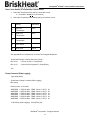
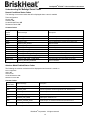
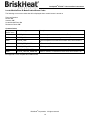
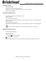
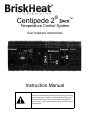
® Centipede 2 ™ Temperature Control System User Interface Instructions Instruction Manual Read and understand this material before operating or servicing these heating tapes. Failure to understand how to safely operate these heaters could result in an accident causing serious injury or death. These heaters should only be operated by qualified personnel. ® Centipede2 STACK™ User Interface Instructions Table of Contents LUI/ RS-232 Setup.......................................................................................................................................... 4 Hardware Requirements ...................................................................................................................... 4 RS-232 Communication Set-up ........................................................................................................... 4 Telnet over Ethernet Setup ........................................................................................................................... 5 Setting Up IP Address through a Windows XP-based PC ................................................................... 5 Setting Up Hyper Terminal Through a Windows XP-based PC ........................................................... 6 Log-In Instructions ........................................................................................................................................ 8 User Interface Command List ...................................................................................................................... 8 Detect and Assign Control Zone IDs ........................................................................................................... 9 Enumerate Control Zone IDs ............................................................................................................... 9 Detect and View Control Zones ........................................................................................................... 9 Reset Zone IDs and Settings ............................................................................................................... 9 Reload .................................................................................................................................................. 9 Manually Set and Individual Zone ID ................................................................................................... 10 Manually Set Multiple Zone IDs ........................................................................................................... 10 Program Temperature Control Zones .................................................................................................. 11 Read / View Status of Temperature Control Zones ............................................................................. 12 Dump Command (Data Logging) ......................................................................................................... 12 Setting Alarm Relay - Latching Alarm Feature ........................................................................................... 13 Alarm Relay Summary Table ............................................................................................................... 13 Understanding the Message Status Codes ................................................................................................ 14 Normal Conditions Status Codes ......................................................................................................... 14 Autotune Mode Enabled Status Codes ................................................................................................ 14 Locate Module / Zone ID Mode Enabled Status Codes ....................................................................... 15 Operator Interface Set-up ............................................................................................................................. 16 Time and Date Set-up .......................................................................................................................... 16 Password Change ................................................................................................................................ 17 Communication Mode Set-up............................................................................................................... 17 Modbus RTU Protocol Set-up .............................................................................................................. 17 TCP / IP Set-up .................................................................................................................................... 18 Display Operator Interface Settings and Firmware Version ................................................................. 18 Locate Zone ID (Orange LED) ...................................................................................................................... 19 Operator Interface Reset .............................................................................................................................. 20 Log Out Instructions (Exit Session) ............................................................................................................ 20 Appendix A: Centipede 2® Operator Interface Register Definitions ......................................................... 21 Appendix B: Centipede 2® Control Zone Register Definitions ................................................................. 22 Appendix C: Alarm Relay Setup .................................................................................................................. 24 Appendix D: Controller Configuration Commands .................................................................................... 29 Appendix E: Understanding the Message Status Codes .......................................................................... 30 Hexidecimal to Binary Conversion Chart.................................................................................................... 30 Trouble Shooting: Status Register Definitions .......................................................................................... 31 Contact Information ...................................................................................................................................... 32 BriskHeat® Corporation. All rights reserved 2 ® Centipede2 STACK™ User Interface Instructions LUI / RS-232 Setup Hardware Requirements Customer supplied communication cable is required to utilize the LUI over RS-232C communications mode. The Centipede 2® requires this straight-through communication cable to use the Male DB9 connector to mate to the Female DB9 installed in the C2STACK-OI. Please terminate the properly sized wire gauge as shown in the below drawing. Follow the connector manufacturer's instructions for proper termination and solder techniques. DNP = Do Not Populate Tx = Transmit Rx = Receive Comm = Common Ground Do not insert any pins or wires into DNP locations. Incorrect pinning and wiring could result in damage to the Centipede 2® Temperature Control System or the ancillary equipment attached to the Centipede 2 ® C2STACK-OI. RS-232 Communication Set-up Ancillary Equipment Communication Parameters Slave mode running on an RS-232 physical layer Baudrate: 19.2k 8 bits, 1 stop bit, and no parity Verify the COM MODE 1 LED is illuminated on the C2STACK-OI BriskHeat® Corporation. All rights reserved 3 ® Centipede2 STACK™ User Interface Instructions TelNet Over Ethernet Setup Setting Up IP Address Through a Windows XP-based PC Step 1: Locate Local Area Connection Properties Start button > Control Panel > Network Connections > Local Area Connection Or Double click on bottom right of screen Click Properties button Step 2: Locate Internet Protocol (TCP / IP) Properties Select Internet Protocol (TCP/IP) Click Properties button BriskHeat® Corporation. All rights reserved 4 LAN icon at ® Centipede2 STACK™ User Interface Instructions Step 3: Input Internet Protocol (TCP/IP) Parameters **Record existing IP address settings if you require previous network access** 1. Select ‘Use the following IP address’: IP address: 192.168.10.1 Subnet mask: 255.255.255.0 2. Click OK button Setting Up HyperTerminal Through a Windows XP-based PC Set up your HyperTerminal location before setting up the HyperTerminal for your system. Step 1: Load HyperTerminal Start button > All programs > Accessories > Communications > Hyper Terminal Or Start button > Run … > type hypertrm > Click OK button BriskHeat® Corporation. All rights reserved 5 ® Centipede2 STACK™ User Interface Instructions Step 2: Input Connection Description Input a Connection Name: Example: “BriskHeat® Centipede 2® Temperature Control” Select Icon Click OK button Step 3: Input the following ‘Connect To’ parameters Host address: 192.168.10.250 Port number : 23 Connect using: TCP / IP (Winsock) Click OK button Step 4: Set-up Hyperterminal Properties To make characters visible when using HyperTerminal follow steps: a) b) c) d) e) Press File Properties Settings Tab Click ASCII Setup Check the box called “Echo Typed Characters Locally” **Do not change any other parameters in this screen** BriskHeat® Corporation. All rights reserved 6 ® Centipede2 STACK™ User Interface Instructions Log-in Instructions for User Interface Screenshot Welcome to Brisk Heat's OEM OI setup Version 1.8.xxx Please enter password: 1. Type in Login password: briskheat (default password) 2. Press [Enter] 3. Retype Login password 4. Press [Enter] 5. List of commands display Operating Instructions: Type a Command and press [Enter] to initiate a command. See Appendix A and B for a list of Register Definitions. Appendix A has a list of register definitions stored on the operator interface. Appendix B has a list of register definitions stored on each temperature control zone. User Interface Command List ‘?’ Command Displays list of commands. Type ? and then press [Enter]. Screenshot Bye Ends this telnet session Reset Resets the program Reload Reloads system to default parameters Show Shows connection settings Sm Shows Enumerated Modules En Enumerate Modules (Query Locked Module/Zone ID(s)) IdReset Resets All Module/Zone ID values to 1-n IdSet: Sets Module/Zone ID values nn:ID (nn=phys position (1-n)) IdSetR: Sets Module/Zone ID values nn:ID:qty (nn=phys position (1-n)) lmon: Locate Module/Zone ID and blink corresponding LED lmon:ID lmoff Discontinue Module/Zone ID locate Unlatch One-shot unlatching of all latched heater alarms LUIOn Enable RS-232 Local User Interface LUIOff Disable RS-232 Local User Interface ModAddr: Modbus Address ModAddr:Address (address = 1-255) Dnsaddress1: Sets the first dns address to use on network Dnsaddress2: Sets the backup dns address to use on network Password: Sets the case sensitive password Ipaddress: Sets ip address to use when connecting to server Settime: Sets local time hh:mm:ss mm/dd/yyyy format Gateway: Sets gateway address to use to get to internet Netmask: Sets up the tcpip netmask Timezone: 0 for utc, offset for local time Rr: Reads register RR:register number Wr: Write register WR:register,value,additional params Dump: Dumps data to screen, optional param is time in seconds * Modbus RTU mode is off when Local User Interface mode is on: Com Mode 1 ** Modbus RTU mode is on when Local User Interface mode is off: Com Mode 2 BriskHeat® Corporation. All rights reserved 7 ® Centipede2 STACK™ User Interface Instructions Detect and Assign Control Zone IDs Enumerate Control Zone IDs ‘En’ Command Type En and then press [Enter]. Detects all installed zones. Any control zone without a Zone ID will be auto-assigned a Zone ID based on its physical location. E.g. Zones 1,2,3,4,5,…. After performing the ‘En’ function, perform the ‘Sm’ command to confirm that the required zones are detected. See Detect and View Control Zones. Screenshot: BH> en Enumerating Modules Detect and View Control Zones ‘Sm’ Command Type Sm and then press [Enter]. Displays all zones with a Zone ID. Verify that the required numbers of zones are detected for your installation. If there are multiple zones with the same Zone ID or there are missing zones, perform an IDRESET. See Reset Zone IDs and Settings. Screenshot: BH> sm Enumerated modules 1, 2, 3 Reset Zone IDs and Settings ‘Idreset’ Command Type Idreset and then press [Enter]. Resets and auto-assigns all Zone IDs. This function should be performed when there are multiple zones with the same Zone ID (e.g. 1, 1, 2, 2, 3, 3) or when you wish to reset all temperature zone register values. This function resets all temperature zone register values (set-point, high-limit, etc.) back to its default parameters. See Appendix B for a list of all default module register values. Screenshot: BH> sm Enumerated modules 1, 1, 2 BH> idreset Resetting Module/Zone ID(s) BH> sm Enumerated modules 1, 2, 3 BriskHeat® Corporation. All rights reserved 8 ® Centipede2 STACK™ User Interface Instructions Manually Set an Individual Zone ID ‘Idset’ Command Type Idset:X:Y and then press [Enter]. X = Physical Zone Location Y = Desired Zone ID # Set a specific Zone ID number to a single zone. In the screenshot example below, the user changes the Zone ID of the first zone to 55. Screenshot: BH> idset:1:55 Setting Module/Zone ID BH> sm Enumerated modules 55, 2, 3 Manually Set Multiple Zone IDs ‘Idsetr’ Command Type Idsetr:X:Y:Z and then press [Enter]. X = Physical Zone Location of the First Zone to Change Y = Desired Zone ID # of First Zone to Change Z = Number of Zones to Change Set multiple zone IDs in sequence at one time. In the screenshot example below, the user changes the Zone ID of the fourth physical zone to 10. The user also requires three zone IDs to be assigned starting with the fourth physical zone. The three zones are re-assigned to the desired sequence: 10, 11, 12. Screenshot: BH> idsetr:4:10:3 Setting Module/Zone ID BH> sm Enumerated modules 1, 2, 3, 10, 11, 12 Reload Default Parameters ‘Reload’ Command Type Reload and then press [Enter]. Screenshot: BH> reload Reloading default parameters BriskHeat® Corporation. All rights reserved 9 ® Centipede2 STACK™ User Interface Instructions Program Temperature Control Zones 1. Select the Temperature Zone that you would like to program A. Option 1: Program All Temperature Zones: Command: wr:3,0 B. Option 2: Program an Individual Zone Command: wr:3,X (X= zone number) 2. Select the Temperature Zone Setting that you would like to program Setting Command Example 1 Set-Point Temperature wr:4,5,X00 (X= temperature in °C) wr:4,5,15000 Programs set-point to 150.00°C 2 High-Limit Temperature wr:4,6,X00 (X= temperature in °C) wr:4,6,17000 Programs high-limit to 170.00°C 3 Low-Limit Temperature wr:4,7,X00 (X= temperature in °C) wr:4,7,13000 Programs low-limit to 130.00°C 4 Disable / Enable Zone Disable: wr:4,2,0 Enable: wr:4,2,32768 Default setting: Enabled 5 PID Auto tune wr:4,2,40960 See Appendix B for a complete list of Control Zone Register Definitions. Screenshot of Global Programming BH> wr:3,0 ß Focus on all zones. Press [Enter] BH> wr:4,5,15000 ß Set-Point 150°C. Press [Enter] BH> wr:4,6,17000 ß High-Temperature Limit 170°C. Press [Enter] BH> wr:4,7,13000 ß Low-Temperature Limit 130°C. Press [Enter] Screenshot of Individual Zone, Example: Zone 2 BH> wr:3,2 ß Focus on individual zone. Press [Enter] BH> wr:4,5,14000 ß Set-Point 140°C. Press [Enter] BH> wr:4,6,18000 ß High-Temperature Limit 180°C. Press [Enter] BH> wr:4,7,12000 ß Low-Temperature Limit 120°C. Press [Enter] BriskHeat® Corporation. All rights reserved 10 ® Centipede2 STACK™ User Interface Instructions Read / View Status of Temperature Control Zones 1. Select the Temperature Zone that you would like to view A. Command: wr:3,X (X= zone number) 2. Select the Temperature Zone Setting that you would like to view Setting Command 1 Set-Point Temperature rr:4,5 2 High-Limit Temperature rr:4,6 3 Low-Limit Temperature rr:4,7 4 Zone Status 5 Duty Cycle rr:4,2 rr:4,12 See Appendix B for a complete list of Control Zone Register Definitions. Screenshot Example: Viewing Set-Point of Zone 1 BH> wr:3,1 ß Focus on zone 1. Press [Enter] BH> rr:4,5 ß View Set-Point (register 5). Press [Enter] 150 Dump Command (Data Logging) Type dump [Enter] Screenshot of Dump Command (Data Logging) BH> dump Data log every 10 seconds ADDRESS ADDRESS ADDRESS ADDRESS ADDRESS ADDRESS 1 STATUS 8001 2 STATUS 8001 3 STATUS 8001 1 STATUS 8001 2 STATUS 8001 3 STATUS 8001 TEMP TEMP TEMP TEMP TEMP TEMP 150.01 C 150.01 C 150.02 C 150.03 C 150.02 C 150.01 C DUTY DUTY DUTY DUTY DUTY DUTY 40 40 41 39 39 40 To Exit Dump (Data Logging): Press [Enter] key BriskHeat® Corporation. All rights reserved 11 ® Centipede2 STACK™ User Interface Instructions Setting Alarm Relay - Latching Alarm Feature The Centipede 2® has a built in alarm relay with latching alarm feature that is user configurable for your application. Each condition to which latching applies (See Alarm Operation Summary Table) will be individually enabled. The term latching means that when a condition’s actuation criteria are met, the alarm, all of its control actions, and outward indicators will remain in their actuated state until the condition is unlatched by user intervention (i.e. If a high temp alarm condition occurs, the individual zone will remain in the non-heating mode until a user unlatches the zone). The alarm unlatch setting can be accessed on the text user interface which will momentarily unlatch all latched alarms. The unlatch function will unlatch all zones simultaneously. Any zones that are considered to be in alarm mode will re-latch. Refer to Appendix C to determine the code for your alarm needs. Alarm Relay Summary Table *Low heater and High heater are warnings that only are reflected in the dump query report Condition Control Action Latch Configuration Type Scope Storage Low Temp Timer Configuration Default Scope Default Alarm Relay LED Yes Yes Yes Yes High Temp disable heat user Global Non-volatile enabled n/a Low Temp none user Global Non-volatile disabled Global Open RTD disable heat user Global Non-volatile disabled n/a Yes Yes Short RTD disable heat user Global Non-volatile disabled n/a Yes Yes Open Heater disable heat user Global Non-volatile enabled n/a Yes Yes Short Heater disable heat user Global Non-volatile enabled n/a Yes Yes Low Heater None None n/a n/a n/a n/a No1 No High Heater None None n/a n/a n/a n/a No1 No BriskHeat® Corporation. All rights reserved 12 30 min ® Centipede2 STACK™ User Interface Instructions Understanding the Message Status Codes Normal Conditions Status Codes The following are common codes that will be displayed when a zone is enabled Zone configuration Heater: On Autotune: Off Locate Module/Zone: Off Resistance Check: Off Common Codes Displayed Status Value Status Message Description 8001 STATUS_OK Current temperature is within alarm limits 8002 STATUS_HIGH Current temperature is above high alarm limit 8004 STATUS_LOW Current temperature is below the low alarm limit 8008 STATUS_RTD_SHORT RTD is shorted 8010 STATUS_RTD_OPEN RTD is open 8020 STATUS_HEATER_OPEN Heater is open, or resistance is above limit 8040 STATUS_HEATER_SHORTED Heater is shorted, or resistance is below limit 8080 STATUS_TRIAC_DRIVER_BAD Triac driver is not responding 8100 / 8101 STATUS_NETWORK_COMMS_BAD Communications channel is bad 8200 / 8201 STATUS_HEATER_CONFIG_COMM_BAD Communication failed during heater configuration 8400 / 8401 STATUS_LINE_CTRL_COMM_BAD Communication error with heater line module 4 STATUS_HEATER_DISABLED Zone is disabled See Appendix C for a complete list of status codes. Autotune Mode Enabled Status Codes The following are common codes that will be displayed when Autotune is turned on Zone configuration Heater: On Autotune: On Locate Module/Zone: Off Resistance Check: Off Common Codes Displayed Status Value Status Message Description a001 STATUS_OK Current temperature is within alarm limits; Autotune is on a002 STATUS_HIGH Current temperature is above high alarm limit; Autotune is on a004 STATUS_LOW Current temperature is below the low alarm limit; Autotune is on a008 STATUS_RTD_SHORT RTD is shorted; Autotune is on a010 STATUS_RTD_OPEN RTD is open; Autotune is on a020 STATUS_HEATER_OPEN Heater is open, or resistance is above limit; Autotune is on a040 STATUS_HEATER_SHORTED Heater is shorted, or resistance is below limit; Autotune is on See Appendic C for a complete list of status codes BriskHeat® Corporation. All rights reserved 13 ® Centipede2 STACK™ User Interface Instructions Locate Module/Zone ID Mode Enabled Status Codes The following are common codes that will be displayed when module locator is turned on Zone configuration Heater: On Autotune: Off Locate Module/Zone: On Resistance Check: Off Common Codes Displayed Status Value 9001 Status Message Description STATUS_OK Current temperature is within alarm limits; Zone Locator is on 9002 STATUS_HIGH Current temperature is above high alarm limit; Zone Locator is on 9004 STATUS_LOW 9008 STATUS_RTD_SHORT Current temperature is below the low alarm limit; Zone Locator is on RTD is shorted; Zone Locator is on 9010 STATUS_RTD_OPEN RTD is open; Zone Locator is on 9020 9040 STATUS_HEATER_OPEN STATUS_HEATER_SHORTED Heater is open, or resistance is above limit; Zone Locator is on Heater is shorted, or resistance is below limit; Zone Locator is on See Appendix C for a complete list of status codes BriskHeat® Corporation. All rights reserved 14 ® Centipede2 STACK™ User Interface Instructions Operator Interface Set-up Time and Date Set-up ‘Settime’ Command Type settime:hh:mm:ss mm/dd/yyyy and then press [Enter]. Sets the local time and date in the following format hh:mm:ss mm/dd/yyyy (e.g. 08:10:00 07/20/2011) ‘Timezone’ Command Type Timezone:XX and then press [Enter]. XX = UCT offset (E.g. –9 is Japan Time Zone) Sets the UCT / GMT time zone for the location of the system. 0 for UCT (default). Input your local time zone by using Figure 9.1 below. Time and Date parameters are reset if power loss or reset command is initiated. Figure 9.1 BriskHeat® Corporation. All rights reserved 15 ® Centipede2 STACK™ User Interface Instructions Password Change ‘Password’ Command Type password: XXXXXX and then press [Enter]. Allows the user to enter a new password for access to the local user interface. Default password: briskheat Communication Mode Set-up The default communication mode is Com Mode 1: LUIon ‘LUIOn’ Command Type LUIOn and then press [Enter]. Turns on the LUI Communication functionality. This can be confirmed by the Com 1 mode light illuminated. ‘LUIOff’ Command Type LUIOff and then press [Enter]. Turns off the LUI Communication functionality. This can be confirmed by the Com 2 mode light illuminated. You must connect via Ethernet over Telnet to turn on the LUI interface over to RS-232C. Modbus RTU Protocol Set-up The default Modbus address is 0. ‘ModAddr’ Command Type modaddr:XXX and then press [Enter]. XXX = ModBus Address 0 through 255 Sets the ModBus address for the operator interface when communicating using ModBus RTU protocol. BriskHeat® Corporation. All rights reserved 16 ® Centipede2 STACK™ User Interface Instructions TCP/IP Set-up The default TCP/IP settings are generally appropriate for a single Centipede 2® Operator Interface. If multiple Centipede 2® Operator Interfaces are on the same network, multiple TCP/IP addresses are required. ‘Dnsaddress1’ Command Type Dnsaddress1:xxx.xxx.xx.xxx and then press [Enter]. Sets the first dns address to use on network. ‘Dnsaddress2’ Command Type Dnsaddress2:xxx.xxx.xx.xxx and then press [Enter]. Sets the backup dns address to use on network. ‘Ipaddress’ Command Type Ipaddress:xxx.xxx.xx.xxx and then press [Enter]. Sets the IP address to use when connecting to a server. ‘Gateway’ Command Type Gateway:xxx.xxx.xx.x and then press [Enter]. Sets gateway address to use to get to Internet. ‘Netmask’ Command Type Netmask:xxx.xxx.xxx.x and then press [Enter]. Sets up the TCP/IP netmask. Display Operator Interface Settings and Firmware Version ‘Show’ Command Type Show and then press [Enter]. Screenshot BH> show Version 1.8.xxx Ip address: 192.168.10.250 Gateway address: 192.168.10.1 Netmask: 255.255.255.0 Dns address1: 192.168.10.104 Dns address2: 64.118.139.51 BriskHeat® Corporation. All rights reserved 17 ® Centipede2 STACK™ User Interface Instructions Locate Zone ID (Orange LED) Quickly detect the location of a zone by causing the LED to flash orange. This function does not affect the performance of the zone control. The zone will remain in the flashing position until the user turns it off or selects a different zone. ‘Lmon’ Command Type Lmon:X and then press [Enter]. X = Zone ID to Locate (e.g. 1 = Zone 1) Turns on LED of corresponding Zone ID to flash Orange. See Figures 10.1 and 10.2. Figure 10.2 Image of flashing orange light on C2MOD-C Figure 10.1 Image of flashing orange light on C2STACK-CR Screenshot: BH> lmon:1 BH> ‘Lmoff’ Command Type Lmoff:X and then press [Enter]. X = Zone ID to Locate (e.g. 1 = Zone 1) Turns off LED of corresponding Zone ID to no longer flash orange. Screenshot: BH> lmoff:1 BH> BriskHeat® Corporation. All rights reserved 18 ® Centipede2 STACK™ User Interface Instructions Operator Interface Reset ‘Reset’ Command Type Reset and then press [Enter]. Resets the operator interface. The communications session ends. This is the equivalent as turning the power off to the operator interface and turning it back on. Screenshot: Welcome to Brisk Heat's OEM OI setup Version 1.8.xxx Please enter password: Time and Date parameters are reset if power loss or reset command is initiated. Exit Session ‘Bye’ Command Type bye and then press [Enter]. Ends the current communications session. The Centipede 2® continues to operate after exiting the communication session. Screenshot: BH>bye Disconnected BriskHeat® Corporation. All rights reserved 19 ® Centipede2 STACK™ User Interface Instructions Appendix A: Centipede 2® Operator Interface Register Definitions Register Description Address Memory Access Default Description Firmware Revision 0 flash R NA Controller Status Word 1 Flash R NA Modbus Comms Error Reg 2 RAM R/W 0 Module Focus Address 3 RAM R/W 0 Jacket Module address Jacket Command Register 4 RAM R/W Jacket Poll response register 5 RAM R Time1 6 RTC R/W Current time BCD hours, minutes Time2 7 RTC R/W Current time BCD seconds, month Time3 8 RTC R/W Current time BCD day, year Module address 9 EEPROM R/W 0 Modbus addr Module (controller) Settings 10 EEPROM R/W 1 Settings Low Temperature Timer 11 EEPROM R/W 1800 Low temp timer (secs) Reserved 12-100 BriskHeat® Corporation. All rights reserved 20 ® Centipede2 STACK™ User Interface Instructions Appendix B: Centipede 2® Control Zone Register Definitions Register Description Address Memory Access Default Description Firmware Revision 0 flash R NA Line Processor Revision 1 Flash R NA Heater Status Sampled Temperature 2 3 Ram Ram R/W R NA NA Controller Config Register 4 EEPROM R/W 64 Temperature Setpoint 5 EEPROM R/W 0 0.00 C Temperature Hi Limit alarm 6 EEPROM R/W 0 0.00 C Temperature Lo Limit alarm 7 EEPROM R/W 0 0.00 C 100 Ohm Calibration value hi 8 EEPROM R 6800 Ohms * 100 100 Ohm Calibration value lo 9 EEPROM R 6800 Ohms * 100 Reserved 10 - 12 NA NA NA PID Pg Current value 13 Ram R NA PID Pd Current value 14 Ram R NA PID Pi Current value 15 Ram R NA Current PWM percentage 16 Ram R NA ADC Raw Data value 17 Ram R NA Reserved 18 - 100 NA NA NA Deg c * 100 Appendix C: Alarm Relay Setup: wr.10,”Value” VALUE ENABLED ALARM FEATURES 0 NOTHING ENABLED 1 ALARM RELAY ENABLED 2 LOW TEMP LATCH ENABLED, 3 LOW TEMP LATCH ENABLED, ALARM RELAY ENABLED 4 HIGH TEMP LATCH ENABLED, 5 HIGH TEMP LATCH ENABLED, ALARM RELAY ENABLED 6 HIGH TEMP LATCH ENABLED, LOW TEMP LATCH ENABLED, 7 HIGH TEMP LATCH ENABLED, LOW TEMP LATCH ENABLED, ALARM RELAY ENABLED 8 OPEN RTD LATCH ENABLED, 9 OPEN RTD LATCH ENABLED, ALARM RELAY ENABLED 10 OPEN RTD LATCH ENABLED, LOW TEMP LATCH ENABLED, 11 OPEN RTD LATCH ENABLED, LOW TEMP LATCH ENABLED, ALARM RELAY ENABLED BriskHeat® Corporation. All rights reserved 21 ® Centipede2 STACK™ User Interface Instructions Appendix C: Alarm Relay Setup Continued VALUE ENABLED ALARM FEATURES 12 OPEN RTD LATCH ENABLED, HIGH TEMP LATCH ENABLED, 13 OPEN RTD LATCH ENABLED, HIGH TEMP LATCH ENABLED, ALARM RELAY ENABLED 14 OPEN RTD LATCH ENABLED, HIGH TEMP LATCH ENABLED, LOW TEMP LATCH ENABLED, 15 OPEN RTD LATCH ENABLED, HIGH TEMP LATCH ENABLED, LOW TEMP LATCH ENABLED, ALARM RELAY ENABLED 16 SHORT RTD LATCH ENABLED, 17 SHORT RTD LATCH ENABLED, ALARM RELAY ENABLED 18 SHORT RTD LATCH ENABLED, LOW TEMP LATCH ENABLED, 19 SHORT RTD LATCH ENABLED, LOW TEMP LATCH ENABLED, ALARM RELAY ENABLED 20 SHORT RTD LATCH ENABLED, HIGH TEMP LATCH ENABLED, 21 SHORT RTD LATCH ENABLED, HIGH TEMP LATCH ENABLED, ALARM RELAY ENABLED 22 SHORT RTD LATCH ENABLED, HIGH TEMP LATCH ENABLED, LOW TEMP LATCH ENABLED, 23 SHORT RTD LATCH ENABLED, HIGH TEMP LATCH ENABLED, LOW TEMP LATCH ENABLED, ALARM RELAY ENABLED 24 SHORT RTD LATCH ENABLED, OPEN RTD LATCH ENABLED, 25 SHORT RTD LATCH ENABLED, OPEN RTD LATCH ENABLED, ALARM RELAY ENABLED 26 SHORT RTD LATCH ENABLED, OPEN RTD LATCH ENABLED, LOW TEMP LATCH ENABLED, 27 SHORT RTD LATCH ENABLED, OPEN RTD LATCH ENABLED, LOW TEMP LATCH ENABLED, 28 SHORT RTD LATCH ENABLED, OPEN RTD LATCH ENABLED, HIGH TEMP LATCH ENABLED, 29 SHORT RTD LATCH ENABLED, OPEN RTD LATCH ENABLED, HIGH TEMP LATCH ENABLED, ALARM RELAY ENABLED 30 SHORT RTD LATCH ENABLED, OPEN RTD LATCH ENABLED, HIGH TEMP LATCH ENABLED, LOW TEMP LATCH ENABLED, 31 SHORT RTD LATCH ENABLED, OPEN RTD LATCH ENABLED, HIGH TEMP LATCH ENABLED, LOW TEMP LATCH ENABLED, ALARM RELAY ENABLED 32 OPEN HEATER LATCH ENABLED, 33 OPEN HEATER LATCH ENABLED, ALARM RELAY ENABLED 34 OPEN HEATER LATCH ENABLED, LOW TEMP LATCH ENABLED, 35 OPEN HEATER LATCH ENABLED, LOW TEMP LATCH ENABLED, ALARM RELAY ENABLED 36 OPEN HEATER LATCH ENABLED, HIGH TEMP LATCH ENABLED, 37 OPEN HEATER LATCH ENABLED, HIGH TEMP LATCH ENABLED, ALARM RELAY ENABLED BriskHeat® Corporation. All rights reserved 22 ® Centipede2 STACK™ User Interface Instructions Appendix C: Alarm Relay Setup Continued 38 39 OPEN HEATER LATCH ENABLED, HIGH TEMP LATCH ENABLED, LOW TEMP LATCH ENABLED, OPEN HEATER LATCH ENABLED, HIGH TEMP LATCH ENABLED, LOW TEMP LATCH ENABLED, ALARM RELAY ENABLED 40 OPEN HEATER LATCH ENABLED, OPEN RTD LATCH ENABLED, 41 OPEN HEATER LATCH ENABLED, OPEN RTD LATCH ENABLED, ALARM RELAY ENABLED 42 OPEN HEATER LATCH ENABLED, OPEN RTD LATCH ENABLED, LOW TEMP LATCH ENABLED, 43 OPEN HEATER LATCH ENABLED, OPEN RTD LATCH ENABLED, LOW TEMP LATCH ENABLED, ALARM RELAY ENABLED 44 OPEN HEATER LATCH ENABLED, OPEN RTD LATCH ENABLED, HIGH TEMP LATCH ENABLED, 45 46 47 OPEN HEATER LATCH ENABLED, OPEN RTD LATCH ENABLED, HIGH TEMP LATCH ENABLED, ALARM RELAY ENABLED OPEN HEATER LATCH ENABLED, OPEN RTD LATCH ENABLED, HIGH TEMP LATCH ENABLED, LOW TEMP LATCH ENABLED, OPEN HEATER LATCH ENABLED, OPEN RTD LATCH ENABLED, HIGH TEMP LATCH ENABLED, LOW TEMP LATCH ENABLED, ALARM RELAY ENABLED 48 OPEN HEATER LATCH ENABLED, SHORT RTD LATCH ENABLED, 49 OPEN HEATER LATCH ENABLED, SHORT RTD LATCH ENABLED, ALARM RELAY ENABLED 50 OPEN HEATER LATCH ENABLED, SHORT RTD LATCH ENABLED, LOW TEMP LATCH ENABLED, 51 OPEN HEATER LATCH ENABLED, SHORT RTD LATCH ENABLED, LOW TEMP LATCH ENABLED, ALARM RELAY ENABLED 52 OPEN HEATER LATCH ENABLED, SHORT RTD LATCH ENABLED, HIGH TEMP LATCH ENABLED, 53 54 55 56 57 58 59 60 61 62 63 OPEN HEATER LATCH ENABLED, SHORT RTD LATCH ENABLED, HIGH TEMP LATCH ENABLED, ALARM RELAY ENABLED OPEN HEATER LATCH ENABLED, SHORT RTD LATCH ENABLED, HIGH TEMP LATCH ENABLED, LOW TEMP LATCH ENABLED, OPEN HEATER LATCH ENABLED, SHORT RTD LATCH ENABLED, HIGH TEMP LATCH ENABLED, LOW TEMP LATCH ENABLED, ALARM RELAY ENABLED OPEN HEATER LATCH ENABLED, SHORT RTD LATCH ENABLED, OPEN RTD LATCH ENABLED, OPEN HEATER LATCH ENABLED, SHORT RTD LATCH ENABLED, OPEN RTD LATCH ENABLED, ALARM RELAY ENABLED OPEN HEATER LATCH ENABLED, SHORT RTD LATCH ENABLED, OPEN RTD LATCH ENABLED, LOW TEMP LATCH ENABLED, OPEN HEATER LATCH ENABLED, SHORT RTD LATCH ENABLED, OPEN RTD LATCH ENABLED, LOW TEMP LATCH ENABLED, ALARM RELAY ENABLED OPEN HEATER LATCH ENABLED, SHORT RTD LATCH ENABLED, OPEN RTD LATCH ENABLED, HIGH TEMP LATCH ENABLED, OPEN HEATER LATCH ENABLED, SHORT RTD LATCH ENABLED, OPEN RTD LATCH ENABLED, HIGH TEMP LATCH ENABLED, ALARM RELAY ENABLED OPEN HEATER LATCH ENABLED, SHORT RTD LATCH ENABLED, OPEN RTD LATCH ENABLED, HIGH TEMP LATCH ENABLED, LOW TEMP LATCH ENABLED, OPEN HEATER LATCH ENABLED, SHORT RTD LATCH ENABLED, OPEN RTD LATCH ENABLED, HIGH TEMP LATCH ENABLED, LOW TEMP LATCH ENABLED, ALARM RELAY ENABLED 64 SHORT HEATER LATCH ENABLED, 65 SHORT HEATER LATCH ENABLED, ALARM RELAY ENABLED 66 SHORT HEATER LATCH ENABLED, LOW TEMP LATCH ENABLED BriskHeat® Corporation. All rights reserved 23 ® Centipede2 STACK™ User Interface Instructions Appendix C: Alarm Relay Setup Continued 67 SHORT HEATER LATCH ENABLED, LOW TEMP LATCH ENABLED, ALARM RELAY ENABLED 68 SHORT HEATER LATCH ENABLED, HIGH TEMP LATCH ENABLED, 69 SHORT HEATER LATCH ENABLED, HIGH TEMP LATCH ENABLED, ALARM RELAY ENABLED 70 SHORT HEATER LATCH ENABLED, HIGH TEMP LATCH ENABLED, LOW TEMP LATCH ENABLED, 71 SHORT HEATER LATCH ENABLED, HIGH TEMP LATCH ENABLED, LOW TEMP LATCH ENABLED, 72 SHORT HEATER LATCH ENABLED, OPEN RTD LATCH ENABLED, 73 SHORT HEATER LATCH ENABLED, OPEN RTD LATCH ENABLED, ALARM RELAY ENABLED 74 SHORT HEATER LATCH ENABLED, OPEN RTD LATCH ENABLED, LOW TEMP LATCH ENABLED, 75 SHORT HEATER LATCH ENABLED, OPEN RTD LATCH ENABLED, LOW TEMP LATCH ENABLED, 76 SHORT HEATER LATCH ENABLED, OPEN RTD LATCH ENABLED, HIGH TEMP LATCH ENABLED, 77 SHORT HEATER LATCH ENABLED, OPEN RTD LATCH ENABLED, HIGH TEMP LATCH ENABLED, 78 79 SHORT HEATER LATCH ENABLED, OPEN RTD LATCH ENABLED, HIGH TEMP LATCH ENABLED, LOW TEMP LATCH ENABLED, SHORT HEATER LATCH ENABLED, OPEN RTD LATCH ENABLED, HIGH TEMP LATCH ENABLED, LOW TEMP LATCH ENABLED, ALARM RELAY ENABLED 80 SHORT HEATER LATCH ENABLED, SHORT RTD LATCH ENABLED, 81 SHORT HEATER LATCH ENABLED, SHORT RTD LATCH ENABLED, ALARM RELAY ENABLED 82 SHORT HEATER LATCH ENABLED, SHORT RTD LATCH ENABLED, LOW TEMP LATCH ENABLED, 83 SHORT HEATER LATCH ENABLED, SHORT RTD LATCH ENABLED, LOW TEMP LATCH ENABLED, 84 SHORT HEATER LATCH ENABLED, SHORT RTD LATCH ENABLED, HIGH TEMP LATCH ENABLED, 85 SHORT HEATER LATCH ENABLED, SHORT RTD LATCH ENABLED, HIGH TEMP LATCH ENABLED, 86 87 SHORT HEATER LATCH ENABLED, SHORT RTD LATCH ENABLED, HIGH TEMP LATCH ENABLED, LOW TEMP LATCH ENABLED, SHORT HEATER LATCH ENABLED, SHORT RTD LATCH ENABLED, HIGH TEMP LATCH ENABLED, LOW TEMP LATCH ENABLED, ALARM RELAY ENABLED 88 SHORT HEATER LATCH ENABLED, SHORT RTD LATCH ENABLED, OPEN RTD LATCH ENABLED, 89 SHORT HEATER LATCH ENABLED, SHORT RTD LATCH ENABLED, OPEN RTD LATCH ENABLED, 90 91 92 93 94 95 SHORT HEATER LATCH ENABLED, SHORT RTD LATCH ENABLED, OPEN RTD LATCH ENABLED, LOW TEMP LATCH ENABLED, SHORT HEATER LATCH ENABLED, SHORT RTD LATCH ENABLED, OPEN RTD LATCH ENABLED, LOW TEMP LATCH ENABLED, ALARM RELAY ENABLED SHORT HEATER LATCH ENABLED, SHORT RTD LATCH ENABLED, OPEN RTD LATCH ENABLED, HIGH TEMP LATCH ENABLED, SHORT HEATER LATCH ENABLED, SHORT RTD LATCH ENABLED, OPEN RTD LATCH ENABLED, HIGH TEMP LATCH ENABLED, ALARM RELAY ENABLED SHORT HEATER LATCH ENABLED, SHORT RTD LATCH ENABLED, OPEN RTD LATCH ENABLED, HIGH TEMP LATCH ENABLED, LOW TEMP LATCH ENABLED, SHORT HEATER LATCH ENABLED, SHORT RTD LATCH ENABLED, OPEN RTD LATCH ENABLED, HIGH TEMP LATCH ENABLED, LOW TEMP LATCH ENABLED, ALARM RELAY ENABLED 96 SHORT HEATER LATCH ENABLED, OPEN HEATER LATCH ENABLED, 97 BriskHeat®OPEN Corporation. AllLATCH rights reserved SHORT HEATER LATCH ENABLED, HEATER ENABLED, ALARM RELAY ENABLED 24 ® Centipede2 STACK™ User Interface Instructions Appendix C: Alarm Relay Setup Continued 98 SHORT HEATER LATCH ENABLED, OPEN HEATER LATCH ENABLED, LOW TEMP LATCH ENABLED 99 SHORT HEATER LATCH ENABLED, OPEN HEATER LATCH ENABLED, LOW TEMP LATCH ENABLED, 100 SHORT HEATER LATCH ENABLED, OPEN HEATER LATCH ENABLED, HIGH TEMP LATCH ENABLED, 101 102 103 SHORT HEATER LATCH ENABLED, OPEN HEATER LATCH ENABLED, HIGH TEMP LATCH ENABLED, ALARM RELAY ENABLED SHORT HEATER LATCH ENABLED, OPEN HEATER LATCH ENABLED, HIGH TEMP LATCH ENABLED, LOW TEMP LATCH ENABLED SHORT HEATER LATCH ENABLED, OPEN HEATER LATCH ENABLED, HIGH TEMP LATCH ENABLED, LOW TEMP LATCH ENABLED, ALARM RELAY ENABLED 104 SHORT HEATER LATCH ENABLED, OPEN HEATER LATCH ENABLED, OPEN RTD LATCH ENABLED, 105 SHORT HEATER LATCH ENABLED, OPEN HEATER LATCH ENABLED, OPEN RTD LATCH ENABLED, 106 107 108 109 110 111 112 113 114 115 116 117 118 119 120 121 SHORT HEATER LATCH ENABLED, OPEN HEATER LATCH ENABLED, OPEN RTD LATCH ENABLED, LOW TEMP LATCH ENABLED, SHORT HEATER LATCH ENABLED, OPEN HEATER LATCH ENABLED, OPEN RTD LATCH ENABLED, LOW TEMP LATCH ENABLED, ALARM RELAY ENABLED SHORT HEATER LATCH ENABLED, OPEN HEATER LATCH ENABLED, OPEN RTD LATCH ENABLED, HIGH TEMP LATCH ENABLED SHORT HEATER LATCH ENABLED, OPEN HEATER LATCH ENABLED, OPEN RTD LATCH ENABLED, HIGH TEMP LATCH ENABLED, ALARM RELAY ENABLED SHORT HEATER LATCH ENABLED, OPEN HEATER LATCH ENABLED, OPEN RTD LATCH ENABLED, HIGH TEMP LATCH ENABLED, LOW TEMP LATCH ENABLED, SHORT HEATER LATCH ENABLED, OPEN HEATER LATCH ENABLED, OPEN RTD LATCH ENABLED, HIGH TEMP LATCH ENABLED, LOW TEMP LATCH ENABLED, ALARM RELAY ENABLED SHORT HEATER LATCH ENABLED, OPEN HEATER LATCH ENABLED, SHORT RTD LATCH ENABLED, SHORT HEATER LATCH ENABLED, OPEN HEATER LATCH ENABLED, SHORT RTD LATCH ENABLED, ALARM RELAY ENABLED SHORT HEATER LATCH ENABLED, OPEN HEATER LATCH ENABLED, SHORT RTD LATCH ENABLED, LOW TEMP LATCH ENABLED SHORT HEATER LATCH ENABLED, OPEN HEATER LATCH ENABLED, SHORT RTD LATCH ENABLED, LOW TEMP LATCH ENABLED, ALARM RELAY ENABLED SHORT HEATER LATCH ENABLED, OPEN HEATER LATCH ENABLED, SHORT RTD LATCH ENABLED, HIGH TEMP LATCH ENABLED SHORT HEATER LATCH ENABLED, OPEN HEATER LATCH ENABLED, SHORT RTD LATCH ENABLED, HIGH TEMP LATCH ENABLED, ALARM RELAY ENABLED SHORT HEATER LATCH ENABLED, OPEN HEATER LATCH ENABLED, SHORT RTD LATCH ENABLED, HIGH TEMP LATCH ENABLED, LOW TEMP LATCH ENABLED, SHORT HEATER LATCH ENABLED, OPEN HEATER LATCH ENABLED, SHORT RTD LATCH ENABLED, HIGH TEMP LATCH ENABLED, LOW TEMP LATCH ENABLED, ALARM RELAY ENABLED SHORT HEATER LATCH ENABLED, OPEN HEATER LATCH ENABLED, SHORT RTD LATCH ENABLED, OPEN RTD LATCH ENABLED SHORT HEATER LATCH ENABLED, OPEN HEATER LATCH ENABLED, SHORT RTD LATCH ENABLED, OPEN RTD LATCH ENABLED, ALARM RELAY ENABLED BriskHeat® Corporation. All rights reserved 25 ® Centipede2 STACK™ User Interface Instructions Appendix C: Alarm Relay Setup Continued 122 123 124 125 126 127 SHORT HEATER LATCH ENABLED, OPEN HEATER LATCH ENABLED, SHORT RTD LATCH ENABLED, OPEN RTD LATCH ENABLED, LOW TEMP LATCH ENABLED, SHORT HEATER LATCH ENABLED, OPEN HEATER LATCH ENABLED, SHORT RTD LATCH ENABLED, OPEN RTD LATCH ENABLED, LOW TEMP LATCH ENABLED, ALARM RELAY ENABLED SHORT HEATER LATCH ENABLED, OPEN HEATER LATCH ENABLED, SHORT RTD LATCH ENABLED, OPEN RTD LATCH ENABLED, HIGH TEMP LATCH ENABLED, SHORT HEATER LATCH ENABLED, OPEN HEATER LATCH ENABLED, SHORT RTD LATCH ENABLED, OPEN RTD LATCH ENABLED, HIGH TEMP LATCH ENABLED, ALARM RELAY ENABLED SHORT HEATER LATCH ENABLED, OPEN HEATER LATCH ENABLED, SHORT RTD LATCH ENABLED, OPEN RTD LATCH ENABLED, HIGH TEMP LATCH ENABLED, LOW TEMP LATCH ENABLED SHORT HEATER LATCH ENABLED, OPEN HEATER LATCH ENABLED, SHORT RTD LATCH ENABLED, OPEN RTD LATCH ENABLED, HIGH TEMP LATCH ENABLED, LOW TEMP LATCH ENABLED, ALARM RELAY ENABLED BriskHeat® Corporation. All rights reserved 26 ® Centipede2 STACK™ User Interface Instructions Appendix D: Controller Configuration Commands: wr:4,4, “Value” Value Bits That are Set 1 Auto Tune On Start Enabled, High Only Temperature Alarm Enabled 16 Adaptive Tuning Enabled, High Only Temperature Alarm Enabled 17 Auto Tune On Start Enabled, Adaptive Tuning Enabled, High Only Temperature Alarm Enabled 32 High and Low Temperature Alarm Enabled 33 Auto Tune On Start Enabled 48 Adaptive Tuning Enabled, High and Low Temperature Alarm Enabled 49 Auto Tune On Start Enabled, Adaptive Tuning Enabled, High and Low Temperature Alarm Enabled 64 High Only Temperature Alarm Enabled, Auto Heat on Start up Enabled 65 Auto Tune On Start Enabled, High Only Temperature Alarm Enabled, Auto Heat on Start up Enabled 80 Adaptive Tuning Enabled, High Only Temperature Alarm Enabled, Auto Heat on Start up Enabled 81 Auto Tune On Start Enabled, Adaptive Tuning Enabled, Auto Heat on Start up Enabled 96 High and Low Temperature Alarm Enabled, Auto Heat on Start up Enabled 97 Auto Tune On Start Enabled, Auto Heat on Start up Enabled 112 Adaptive Tuning Enabled, High and Low Temperature Alarm Enabled, Auto Heat on Start up Enabled 113 Auto Tune On Start Enabled, Adaptive Tuning Enabled, High and Low Temperature Alarm Enabled, Auto Heat on Start up Enabled BriskHeat® Corporation. All rights reserved 27 ® Centipede2 STACK™ User Interface Instructions Appendix E: Understanding the Message Status Codes (Hexidemical to Binary Conversion) To understand the displayed Status code, you first need to convert the displayed hexadecimal code into the equivalent binary code. You can use the conversion charts below to easily convert between hexadecimal and binary. Hexidecimal to Binary Conversion Chart Hexidecimal Value Binary Combination Hexidecimal Value Binary Combination 0 0000 8 1000 1 0001 9 1001 2 0010 a 1010 3 0011 b 1011 4 0100 c 1100 5 0101 d 1101 6 0110 e 1110 7 0111 f 1111 Status Decoding Example: Example: Hex Value of 8401 is displayed is Heater Status Register: Displayed Hex Value 4 8 0 1 Converted Binary Value 1 0 0 0 0 1 0 0 0 0 0 0 0 0 0 1 Bit Position 15 14 13 12 11 10 9 8 7 6 5 4 3 2 1 0 Heater is enabled because bit 15 is set. There is a communication error between the network board and line power board for the zone because bit 10 is set; the heater is within the alarm limits because bit 0 is set. BriskHeat® Corporation. All rights reserved 28 ® Centipede2 STACK™ User Interface Instructions Trouble Shooting: Status Register Definitions Status Code: ____ ____ ____ ____ Last Digit of Status Code Third Digit of Status Code Second Digit of Status Code First Digit of Status Code Value First Digit of Status Code Second Digit of Status Code Third Digit of Status Last Digit of Status Code Code 0 or BLANK 1 BLINK ID 2 ADAPTIVE TUNING ENABLED, 3 ADAPTIVE TUNING ENABLED, BLINK ID 4 START JACKET TEST, 5 START JACKET TEST, BLINK ID 6 START JACKET TEST, ADAPTIVE TUNING ENABLED, 7 START JACKET TEST, ADAPTIVE TUNING ENABLED, BLINK ID 8 ENABLE HEATER CONTROL, 9 ENABLE HEATER CONTROL, BLINK ID A ENABLE HEATER CONTROL, ADAPTIVE TUNING ENABLED, STATUS NETWORK COMMS BAD STATUS HEATER CONFIG COMM BAD, STATUS HEATER CONFIG COMM BAD, STATUS NETWORK COMMS BAD STATUS LINE CTRL COMM BAD, STATUS LINE CTRL COMM BAD, STATUS NETWORK COMMS BAD STATUS LINE CTRL COMM BAD, STATUS HEATER CONFIG COMM BAD, STATUS LINE CTRL COMM BAD, STATUS HEATER CONFIG COMM BAD, STATUS NETWORK COMMS BAD CALIBRATE RTD CIRCUIT, CALIBRATE RTD CIRCUIT, STATUS NETWORK COMMS BAD CALIBRATE RTD CIRCUIT, STATUS HEATER CONFIG COMM BAD, STATUS RTD OPEN STATUS OK STATUS HEATER OPEN, STATUS HIGH, STATUS HEATER OPEN, STATUS RTD OPEN STATUS HIGH, STATUS OK STATUS HEATER SHORTED, STATUS LOW, STATUS HEATER SHORTED, STATUS RTD OPEN STATUS LOW, STATUS OK STATUS HEATER SHORTED, STATUS HEATER OPEN, STATUS LOW, STATUS HIGH, STATUS HEATER SHORTED, STATUS HEATER OPEN, STATUS RTD OPEN STATUS LOW, STATUS HIGH, STATUS OK STATUS TRIAC DRIVER BAD, STATUS RTD SHORT, STATUS TRIAC DRIVER BAD, STATUS RTD OPEN STATUS RTD SHORT, STATUS OK STATUS TRIAC DRIVER BAD, STATUS HEATER OPEN, STATUS RTD SHORT, STATUS HIGH, BriskHeat® Corporation. All rights reserved 29 ® Centipede2 STACK™ User Interface Instructions Value B C D E F First Digit of Status Code Second Digit of Status Third Digit of Code Status Code ENABLE HEATER CONTROL, ADAPTIVE TUNING ENABLED, BLINK ID ENABLE HEATER CONTROL, START JACKET TEST, ENABLE HEATER CONTROL, START JACKET TEST, BLINK ID ENABLE HEATER CONTROL, START JACKET TEST, ADAPTIVE TUNING ENABLED, CALIBRATE RTD CIRCUIT, STATUS HEATER CONFIG COMM BAD, STATUS NETWORK COMMS BAD CALIBRATE RTD CIRCUIT, STATUS LINE CTRL COMM BAD, CALIBRATE RTD CIRCUIT, STATUS LINE CTRL COMM BAD, STATUS NETWORK COMMS BAD ENABLE HEATER CONTROL, START JACKET TEST, ADAPTIVE TUNING ENABLED, BLINK ID CALIBRATE RTD CIRCUIT, STATUS LINE CTRL COMM BAD, STATUS HEATER CONFIG COMM BAD, STATUS NETWORK COMMS BAD CALIBRATE RTD CIRCUIT, STATUS LINE CTRL COMM BAD, STATUS HEATER CONFIG COMM BAD, STATUS TRIAC DRIVER BAD, STATUS HEATER OPEN, STATUS RTD OPEN STATUS TRIAC DRIVER BAD, STATUS HEATER SHORTED, STATUS TRIAC DRIVER BAD, STATUS HEATER SHORTED, STATUS RTD OPEN STATUS TRIAC DRIVER BAD, STATUS HEATER SHORTED, STATUS HEATER OPEN, STATUS TRIAC DRIVER BAD, STATUS HEATER SHORTED, STATUS HEATER OPEN, STATUS RTD OPEN BriskHeat® Corporation. All rights reserved 30 Last Digit of Status Code STATUS RTD SHORT, STATUS HIGH, STATUS OK STATUS RTD SHORT, STATUS LOW, STATUS RTD SHORT, STATUS LOW, STATUS OK STATUS RTD SHORT, STATUS LOW, STATUS HIGH, STATUS RTD SHORT, STATUS LOW, STATUS HIGH, STATUS OK ® Centipede2 STACK™ User Interface Instructions NOTES: BriskHeat® Corporation. All rights reserved 31 ® Centipede2 STACK™ User Interface Instructions 1055 Gibbard Ave, Columbus, OH 43201 Toll Free: 800-848-7673 Phone: 614-294-3376 Fax: 614-294-3807 Email: [email protected] BriskHeat® Corporation. All rights reserved 32 PN: 40890-03 Rev B