1
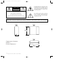
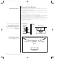
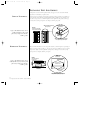
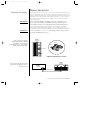
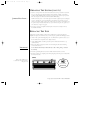
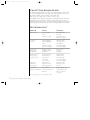
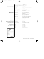
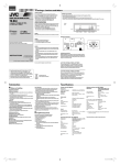
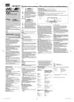
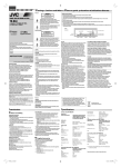
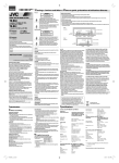
Overture 1-120V OM
9/11/98 4:30 PM
Page 19
Model OVTR 1
3-Way Full-Range Bookshelf Speakers
Owner’s Manual
OVTR 1 Part #331252-001 – 120 Vac Only
®
Overture 1-120V OM
9/11/98 4:30 PM
Page 20
The lightning flash with arrowhead symbol, within
an equilateral triangle, is intended to alert the
user to the presence of uninsulated “dangerous
voltage” within the product’s enclosure that may
be of sufficient magnitude to constitute a risk of
electric shock to persons.
CAUTION
RISK OF ELECTRIC SHOCK
DO NOT OPEN
CAUTION: TO REDUCE THE RISK OF ELECTRIC SHOCK,
The exclamation point within an equilateral
triangle is intended to alert the user to the
presence of important operating and maintenance
(servicing) instructions in the literature
accompanying the product.
DO NOT REMOVE COVER (OR BACK).
NO USER-SERVICEABLE PARTS INSIDE.
REFER SERVICING TO QUALIFIED SERVICE PERSONNEL.
THIS INFINITY PRODUCT IS DESIGNED FOR (USA) 120 VOLT USE ONLY! FOR DETAILED SAFETY
PRECAUTIONS, PLEASE SEE THE ENCLOSED LEAFLET “IMPORTANT SAFETY INSTRUCTIONS” (P/N 330100-001).
OVTR 1
Front
OVTR 1
Side
12 1 ⁄ 2 "
(318 mm)
5 3⁄4"
(146 mm)
OVTR 1
Top
COMPOSITIONS OVERTURE
OVTR 1
OVERALL DIMENSIONS
12 1 ⁄ 2 "
(318 mm)
1 ◆ Compositions Overture OVTR 1 – Owner’s Manual
Overture 1-120V OM
9/11/98 4:30 PM
Page 1
INTRODUCTION
3-WAY BOOKSHELF
SPEAKERS WITH
INTEGRATED POWERED
SUBWOOFERS...
ABOUT THIS MANUAL...
The Infinity Compositions Overture OVTR 1 speaker system is a super-compact, 3-way, fullrange bookshelf or stand-mounted speaker with an integral powered subwoofer. The OVTR 1
is ideal for use where space is at a premium. With its wide bandwidth and uniform response,
it excels in the accurate reproduction of music, but its high efficiency and ability to produce
realistic sound levels with minimal amplifier power make it equally suited for use in the finest
home theater system.
To start enjoying your new pair of Compositions Overture OVTR 1 speakers, first read and then
perform all instructions listed in this manual, as well as those found in the owner’s manuals of
associated components in your audio system. Also, please read the enclosed Important Safety
Instructions for detailed safety precautions. Save all instructions for future reference. These
speakers are covered by a limited five-year warranty (see the back cover), so save the bill of sale
to protect your purchase and aid in any service-related questions.
UNPACKING THE SPEAKERS
Finish unpacking the speaker box. Be careful lifting the speakers, since they are heavier
than they appear. If you suspect damage from transit, report it immediately to your dealer
and/or delivery service. Keep the shipping cartons and packing materials for future use.
Open the accessory pack and verify the following contents:
PARTS LIST...
◆
(2) Molded Feet (For Vertical Placement)
◆
(4) Small Self-Adhesive Feet (For Horizontal Placement)
◆
(4) Large Self-Adhesive Feet (For Horizontal Placement)
◆
(2) Grilles
◆
(4) Spare 2AG 3A SB 250V Fuses
◆
Owner’s Manual (P/N 331214-001) and Warranty Registration Card
You may also need the following tools and supplies:
TOOLS AND SUPPLIES
(NOT ENCLOSED)...
◆
High-quality speaker wire (also see Wiring The System on page 6)
◆
Wire strippers
◆
Small flat-blade screwdriver (for fuse replacement, if needed)
◆
Spade terminals (optional)
Compositions Overture OVTR 1 – Owner’s Manual ◆ 2
Overture 1-120V OM
9/11/98 4:30 PM
Page 2
PLANNING YOUR SYSTEM
STEREO PLACEMENT...
Before deciding where to place your Compositions Overture OVTR 1 speakers, survey your
room and keep the following points in mind:
◆
The OVTR 1 includes a side-firing woofer that requires a minimum 2" (25mm) clearance
from an object, shelf, or wall, whether placed vertically or horizontally, on a bookshelf or
stand (see Figure 1).
NOTE: The stand must be large enough to fully support the speaker.
◆
For vertical placement, make sure the woofers are facing toward or away from each other.
For stability, install the enclosed feet (see Installing Feet and Grilles on page 5).
◆
For best results, try placing the speakers closer together than the distance to the listening area.
◆
Refer to Figure 2 when placing speakers for best bass level and stereo image (also see
Operating The System on page 7).
Figure 1. Compositions Overture OVTR 1
speakers can be positioned vertically or
horizontally for placement on a shelf
or stand. Make sure the side-firing woofer is
at least 2" away from an adjacent object,
shelf, or wall.
Vertical OVTR 1
Wall or
Other Object
Shelf or Other Object
side-firing
woofer
side-firing
woofer
2 " (min.)
Figure 2. Experiment with speaker
placement to obtain the best bass level
and stereo imaging in your room.
move speakers towards corners to increase bass
Left
Channel
angle speakers
inward to
improve stereo
imaging
Listening Area
3 ◆ Compositions Overture OVTR 1 – Owner’s Manual
2 " (min.)
Horizontal
OVTR 1
Right
Channel
Overture 1-120V OM
9/11/98 4:30 PM
Page 3
PLANNING YOUR SYSTEM (CONT ’ D)
HOME THEATER
PLACEMENT...
Compositions Overture OVTR 1 speakers are also suitable for use in reproducing home theater
sound, as shown in Figure 3:
◆
For front left and right channels, place one OVTR 1 speaker on the left and another on the
right, on bookshelves or stands, along either side of the television monitor.
◆
For surround left and right channels, place one OVTR 1 speaker on the left and another on
the right, on bookshelves or stands, behind the listening area.
◆
For center channel use, place one OVTR 1 speaker in the horizontal position on top of or
below the television monitor.
◆
Since the speakers are magnetically shielded, you can set them in very close without
worrying about the field distorting the TV picture.
NOTE: Contact your local Infinity dealer about adding a subwoofer to your system for deep bass
impact on sound effects and music.
Figure 3. Compositions Overture
OVTR 1 speakers are suitable for use
in a home theater system.
Center
(on top or below TV)
Front Right
Front Left
(on shelf)
(on shelf)
Optional
Subwoofer
(on floor)
Rear Left
Surround
Rear Right
Surround
(on stand)
(on stand)
Listening Area
Compositions Overture OVTR 1 – Owner’s Manual ◆ 4
Overture 1-120V OM
9/11/98 4:30 PM
Page 4
INSTALLING FEET AND GRILLES
Compositions Overture OVTR 1 speakers include two types of feet for vertical or horizontal
placement on a shelf, table, or speaker stand.
VERTICAL PLACEMENT...
To insure proper woofer firing, temporarily position the speakers so that the woofer grilles face
each other. On each molded foot, peel the backing from the self-adhesive tape and press each
foot into its respective slot, as shown in Figure 4. Insert a grille into each speaker, so the logo
is nearest the foot. Flip each speaker over and place them in your system.
❶ Peel Backing From Tape
(on top of foot).
MOLDED FOOT
(bottom view)
OVTR 1
MAX
UTILSER UN FUSIBLE DE RECHANGE
DE MEME TYPE ET CALIBRE
ON /
STANDBY
MIN
FUSE
1.6A 250V
BASS
-230V 50Hz
150W MAX
ATTENTION:
CAUTION:
Figure 4. This illustration shows how to
install a molded foot for the vertical
placement of a Compositions Overture
OVTR 1 speaker.
FOR CONTINUED PROTECTION
AGAINST RISK OF FIRE, REPLACE
ONLY WITH SAME TYPE OF FUSE:
2AG SB 250V
(vertical rear views with
woofers facing each other)
–
–
+
8Ω
INPUT
+
8Ω
INPUT
ON /
STANDBY
MAX
-230V 50Hz
150W MAX
BASS
MIN
FUSE
1.6A 250V
Press Against Speaker Bottom.
FOR CONTINUED PROTECTION
AGAINST RISK OF FIRE, REPLACE
ONLY WITH SAME TYPE OF FUSE:
2AG SB 250V
ATTENTION:
UTILSER UN FUSIBLE DE RECHANGE
DE MEME TYPE ET CALIBRE
CAUTION:
HORIZONTAL PLACEMENT...
❷ Place Foot Into Slot And Firmly
Place two small self-adhesive feet on each speaker bottom, as shown in Figure 5. Depending on
where you plan to put the speaker (e.g., TV top), place two large self-adhesive feet 4 to 6 inches
away (refer to Figure 5). Insert a grille into each speaker, so the logo is nearest the foot. Flip
each speaker over and place them in your system.
OVTR 1
(bottom view)
OVTR 1
(horizontal side view
woofer on top)
Figure 5. This illustration shows how to
install self-adhesive feet for the horizontal
placement of a Compositions Overture
OVTR 1 speaker.
❸ Place Large
Feet Here.
side-firing
woofer
place large feet 4"~ 6" away
from small feet
Shelf
❷ Place Small
Feet Here.
❶ Peel Backing From (2) Large And
(2) Small Self-Adhesive Feet.
5 ◆ Compositions Overture OVTR 1 – Owner’s Manual
Overture 1-120V OM
9/11/98 4:30 PM
Page 5
WIRING THE SYSTEM
TURN OFF ALL POWER...
IMPORTANT!
After placing the speakers, you are ready to connect your system. First turn off all audio system
power. Use high-quality speaker wire to make your connections. For speaker connections, use
#18 gauge speaker wire (or #16 for runs over 25 feet) with polarity coding. The side of the wire
with a ridge or other coding is usually considered negative polarity (i.e., – ). Also, consult the
owner’s manuals that were included with your amplifier, receiver, or television to confirm
connection procedures.
If your system includes a Dolby ® Surround Pro Logic® or AC-3 ® preamplifier or A/V
receiver, set the center-channel mode to NORMAL. This will route the low frequencies
(below 100Hz) away from the center-channel speaker to the front left and right speakers.
Observe polarities when making speaker connections, as shown in Figures 6 and 7 below.
Connect each + terminal on the back of the amplifier, receiver, or television to the respective
+ (red) terminal on each OVTR 1 speaker. Similarly, connect the (black) terminals in the same way.
IMPORTANT!
Do not reverse polarities (i.e., + to - or - to +) when making connections. Doing so will cause
poor imaging and diminished bass response.
OVTR 1
(rear view)
Red = +
MAX
Black = –
BASS
MIN
Figure 6. Compositions Overture
OVTR 1 speakers feature gold-plated
terminals that can be connected in
several different ways, e.g., spade terminals,
and direct wiring (as shown here).
–
8Ω
INPUT
+
ON /
STANDBY
FUSE
1.6A 250V
-230V 50Hz
150W MAX
CAUTION:
FOR CONTINUED PROTECTION
AGAINST RISK OF FIRE, REPLACE
ONLY WITH SAME TYPE OF FUSE:
2AG SB 250V
ATTENTION:
UTILSER UN FUSIBLE DE RECHANGE
DE MEME TYPE ET CALIBRE
CONNECTING SPEAKERS DIRECTLY TO WIRES
OVTR 1
Figure 7. Wiring diagram shows polarity
connections for one channel of a stereo or
home theater system.
(rear view)
Receiver or
Amplifier
blk – + red
MAX
MIN
CAUTION:
FOR CONTINUED PROTECTION
AGAINST RISK OF FIRE, REPLACE
ONLY WITH SAME TYPE OF FUSE:
2AG SB 250V
(rear view)
BASS
+
8Ω
INPUT
ON /
STANDBY
FUSE
1.6A 250V
-230V 50Hz
150W MAX
ATTENTION:
UTILSER UN FUSIBLE DE RECHANGE
DE MEME TYPE ET CALIBRE
–
(one channel shown)
Compositions Overture OVTR 1 – Owner’s Manual ◆ 6
Overture 1-120V OM
9/11/98 4:30 PM
Page 6
OPERATING THE SYSTEM
For your convenience, the system is fitted with a power on/off switch. Once the system is
turned on, it will automatically go into a standby mode. Once an audio signal is present, the
system will automatically turn on. It will revert to standby (drawing only 7 watts) when audio is
absent for a minimum of 90 minutes. A dual-color “Power On” LED (see Figure 8 below) glows
red when the amplifier is in the standby mode and green when the amplifier is on.
If you plan to leave for an extended period of time (e.g., vacation), switch the system off
(or unplug the AC power cord).
IMPORTANT!
This product is designed for (USA) 120 Vac use only. Do not connect it to any other
line voltages.
IMPORTANT!
This product is fitted with a 3-prong grounded power cord. Do not use without ensuring the
outlet is grounded.
POWER ON...
1. After speaker wiring has been completed, connect each speaker’s AC power cord to
the nearest AC receptacle. You should see an LED illuminate, indicating the amplifier is
on (see Figure 8 below). If not, verify the AC outlet is delivering power or refer to
Troubleshooting on page 9.
CHECKING PLAYBACK...
2. Check the speakers for playback by first setting the audio system volume control for a
minimum level, and then applying power to your system. Play a favorite music or video
segment and increase the volume control to a comfortable level.
NOTE: You should hear balanced audio reproduction across the entire frequency spectrum. If not,
check all wiring connections and refer to the “Troubleshooting” section on page 9 for more help.
MAX
MIN
More
Bass
Less
Bass
BASS CONTROL
OVTR 1
OVTR 1
ON / STANDBY
Power On
is green
(rear view)
Figure 8. Located on each OVTR 1’s
rear panel are a BASS level control
and a dual-color “Power On” LED.
7 ◆ Compositions Overture OVTR 1 – Owner’s Manual
Standby
is red
“POWER ON” LED
OVTR 1
MAX
CAUTION:
MIN
BASS
FOR CONTINUED PROTECTION
AGAINST RISK OF FIRE, REPLACE
ONLY WITH SAME TYPE OF FUSE:
2AG SB 250V
–
8Ω
INPUT
+
ON /
STANDBY
FUSE
1.6A 250V
-230V 50Hz
150W MAX
ATTENTION:
UTILSER UN FUSIBLE DE RECHANGE
DE MEME TYPE ET CALIBRE
Overture 1-120V OM
9/11/98 4:30 PM
Page 7
OPERATING THE SYSTEM (CONT ’ D)
3. Listen to a variety of music selections and note the bass level. If you feel there is too much
bass, you can reduce it by adjusting the BASS control from the “normal” center-detent
position towards the MIN setting (see Figure 8 on previous page). Conversely, if you want
more bass output, rotate the level control towards the MAX setting.
JUDGING BASS LEVEL...
NOTE: The amount of bass you hear will be affected by a number of different factors, including the
room’s size and shape, the construction materials used to build the room, the listener’s position
relative to the speakers, and the position of the speakers in the room. If there is too much bass, move
the speakers away from nearby walls. Conversely, if you want more bass, place the speakers closer
to the walls (also see Figure 1 on page 3).
4. For safety reasons, the side grille is bonded in place. Please do not attempt to remove.
Potential shock hazard.
REPLACING THE FUSE
Compositions Overture OVTR 1 speakers each use a built-in fuse to protect the subwoofer
amplifier. To replace a fuse with a new one (see enclosed spare), perform the following procedure:
1. Switch off the speaker and unplug the power cord. Then turn the speaker around to access
the fuse holder on the rear panel (refer to Figure 9 below).
2. Using a small flat-blade screwdriver, place the tip in the indent and turn the fuse cap
counterclockwise.
3. Remove the old fuse and replace it with a new one having the same value and rating,
a 2AG 3A SB 250V fuse.
IMPORTANT!
Do not substitute the blown fuse with another fuse value or rating. Doing so will void
the warranty.
4. Insert the cap holding the new fuse into the holder and turn clockwise to lock it.
5. Rotate the speaker to its original position. Then plug the speaker’s AC power cord back into
the nearest AC outlet.
OVTR 1
(rear view)
F
MIN
CAUTION:
FOR CONTINUED PROTECTION
AGAINST RISK OF FIRE, REPLACE
ONLY WITH SAME TYPE OF FUSE:
2AG SB 250V
BASS
–
8Ω
INPUT
+
ON /
STANDBY
FUSE
1.6A 250V
-230V 50Hz
150W MAX
USE
USE
MAX
F
Figure 9. The OVTR 1’s fuse is
located on the rear panel next to the
AC power cord.
ATTENTION:
UTILSER UN FUSIBLE DE RECHANGE
DE MEME TYPE ET CALIBRE
FUSE T 1.6A 250V
OVTR 1 FUSE
Compositions Overture OVTR 1 – Owner’s Manual ◆ 8
Overture 1-120V OM
9/11/98 4:30 PM
Page 8
CARE OF YOUR SPEAKER SYSTEM
The dark grey metallic finish does not require any routine maintenance. When needed,
use a soft cloth, dampened with water only, to remove any fingerprints or to wipe off
dust. Clean the grille by gentle vacuuming or with a damp cloth.
NOTE: Do not use any cleaning products or polishes on the cabinet or grille.
For maximum acoustic transparency, the grille uses a lightweight structure that needs to
be handled with care for removal. To remove the grille, gently pull on the corners to
unfasten the frame from the cabinet. To replace it, make sure to align the frame pins first
and then gently snap the frame into place. Never force the grille frame onto the cabinet.
TROUBLESHOOTING*
SYMPTOM
CAUSE
SOLUTION
Bass is too loud
Bass reinforcement
in room
Move speakers away
from walls
Bass level is too high
Rotate BASS control
toward “1” (see page 8)
Subwoofer amplifier
has reached maximum
output
Turn down volume
control on receiver
or preamplifier
Bass level on preamp/
receiver is set too high
Set bass and treble flat;
use controls sparingly
Distortion with
volume control
near minimum
Defective receiver or
preamplifier; shorted
speaker wires
Repair defective
receiver or
preamplifier
Distortion on music
or effects peaks
(e.g., pops or noise)
Dynamic sound track
causes subwoofer
to “bottom” out
Turn down master
volume control to
lower overall range
Tone controls
are set too high
Set bass and treble flat;
use controls sparingly
Connecting wires
with power on causes
transient signal spikes
Connect wires only
when audio system
power is off
Bass sounds
distorted
Buzz, hum, or
crackle when
connecting wires
No sound from
Power cord not
system; power LED not on connected; no AC power
Blown fuse
*If you need further assistance, contact your local Infinity retail dealer.
9 ◆ Compositions Overture OVTR 1 – Owner’s Manual
Connect AC power cord;
speaker check AC outlet
Check or replace fuse
(see page 8)
Overture 1-120V OM
9/11/98 4:30 PM
Page 9
SPECIFICATIONS – OVTR 1
PERFORMANCE DATA
Frequency Range:
35 ~ 20,000Hz
Sensitivity:
92dB spl @ 1 m/2.83 V (anechoic conditions)
Impedance:
8 Ω nominal
Maximum Peak Output:
108dB (spl on program)
Amplifier Requirements:
Recommended for use with amplifiers
10 ~ 100 W (@ 8 Ω)
Low Frequency:
One 8" (200 mm) high-efficiency,
ultra-linear, long-throw, magneticallyshielded woofer
Mid Frequency:
Two 4" (100 mm) high-efficiency,
magnetically-shielded,
mid-range drivers
High Frequency:
One 1" (25 mm) soft-dome, high-efficiency,
neodymium magnet, magneticallyshielded tweeter
Crossover Frequencies:
300 and 3,000Hz
Peak Output:
250 VA
Power Supply:
120 V~ 60Hz
Power Consumption:
150 W (maximum), 7 W (standby)
DIMENSIONS
Width:
5 3⁄4" (146 mm)
(also see inside front cover)
Height:
12 1⁄2" (318 mm)
Depth:
12 1⁄2" (318 mm)
Weight:
28.5 lb or 12.95 kg (each)
DRIVE UNITS
AMPLIFIER
(BUILT-IN POWER AMPLIFIER FOR
LOW-FREQUENCY SECTION)
Declaration of Conformity
We, Infinity Systems A/S
Kongevejen 194B
DK-3460 Birkerød
DENMARK
declare in own responsibility, that the product described
in this owner’s manual is in compliance with technical
standards:
EN 55 013/6.1990
EN 55 020/6.1988
EN 55 022/6.1993
EN 60 065/1994
EN 60 555-2-3/1987/88
Steen Michaelsen
Infinity Systems A/S
Birkerød. DENMARK. 5/97
Compositions Overture OVTR 1 – Owner’s Manual ◆ 10
Overture 1-120V OM
9/11/98 4:30 PM
Page 10
LIMITED FIVE-YEAR WARRANTY
Who is protected by the warranty?
Your Infinity warranty protects the original retail purchaser and all subsequent owners for a period of five (5) years (parts and labor) for all speaker
components, and one (1) year (parts and labor) for all electronics, from any failure as a result of an original manufacturing defect so long as:
(1) your Infinity loudspeakers were purchased within the fifty states of the U.S.A. or by military personnel from an authorized military outlet and
(2) the original dated bill of sale is presented whenever service is required during the warranty period. This warranty does not apply to products
purchased elsewhere; other purchasers should contact their local Infinity distributor for warranty information.
What does the Infinity warranty cover?
Except as specified below, this warranty covers all defects in original materials and workmanship. The following are not covered: damage caused
by accident, misuse, abuse, neglect, product modification; damage occurring during shipment, damage caused by failure to follow instructions in
the owner’s manual, including failure to perform recommended periodic or routine maintenance; damage resulting from repairs by someone not
authorized by Infinity; claims based upon any misrepresentations by the sellers; and any Infinity product on which the serial number has been
altered, defaced or removed.
Who pays for what?
During the period of this warranty, subject to the above conditions, Infinity will pay all of the labor and material expenses to repair a warrantable
defect.
How can warranty service be obtained?
In the event that your Infinity loudspeaker should require service, you should first contact the Infinity dealer from whom the product was
purchased or, if this is not practical, contact Infinity directly (ATTN: Customer Service) at 20630 Nordhoff Street, Chatsworth, CA 91311
(818) 407-0228. We may direct you to an authorized service center for Infinity products or ask you to send them to us for repair. In either case,
you will have to present your original bill of sale to establish warranty coverage.
Do not send your speaker to us without prior authorization from our Customer Service Department. You are responsible for transporting your
product to either Infinity or an authorized service center and for payment of all shipping charges; however, Infinity will pay the return shipping
charges (in the event you return the product to us) if the repairs are covered by warranty. If you experience difficulty in transporting your product
or are in need of packing materials, please advise us and we may be able to suggest alternative procedures and/or provide adequate packing
materials.
LIMITATION OF IMPLIED WARRANTIES: All implied warranties, including fitness for a particular purpose and merchantability are limited in
duration to the length of the warranty period for your product.
LIMITATION OF INCIDENTAL OR CONSEQUENTIAL DAMAGES: Infinity is not responsible for an incidental or consequential damage of
any kind. Our liability is limited to the repair or replacement, at our option, of a defective product.
Some states do not allow limitations on how long an implied warranty lasts and/or do not allow the exclusion of incidental or consequential
damages, so the above limitations or exclusions may not apply to you. This warranty gives you specific legal rights and you may also have other
rights which vary from state to state.
NOTE: In the event that there is a difference between this warranty and the provisions in any advertisements, product brochure or packaging
cartons, the terms of this warranty will prevail.
Infinity constantly strives to update and improve existing products, as well as create new ones. Therefore the specifications and construction details in this and
related Infinity publications are subject to change without notice.
© 1997 Infinity Systems Inc., 80 Crossways Park West, Woodbury, NY 11797 USA
(516) 496-3400 • FAX (516) 496-4868
Infinity is a registered trademark of Infinity Systems, Inc. Compositions is a trademark of Infinity Systems, Inc. Dolby, Pro Logic, and AC-3 are trademarks of Dolby Laboratories Licensing Corp.
11 ◆ Compositions Overture OVTR 1 – Owner’s Manual
P/N 331214-001