1
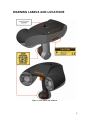
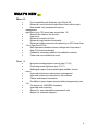
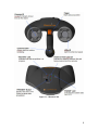
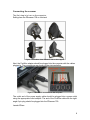
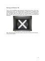
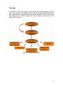
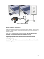
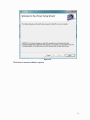
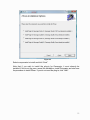
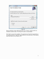
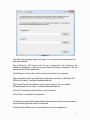
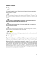
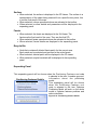
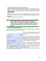
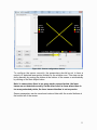
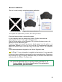
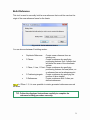
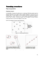
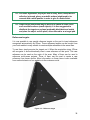
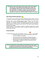
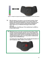
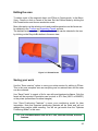
Self-Positioning Handheld 3D Scanner ZScan™1.3 User Guide POWERED BY ZScan: Version 1.3 CAUTION NOTES ...................................................................................................1 LASER WARNING .................................................................................................. 2 WARNING LABELS AND LOCATIONS ................................................................. 3 WHAT’S NEW ........................................................................................................ 4 System Overview ................................................................................................... 5 System description............................................................................................. 5 General care ...................................................................................................... 7 Scanner Manipulation ........................................................................................ 7 Connecting the scanner ................................................................................. 8 Storing your ZScanner 700 ............................................................................ 9 Specifications................................................................................................... 10 Concept............................................................................................................ 11 ZScan™ ................................................................................................................ 12 ZScan minimal required configuration.............................................................. 12 System Installation / Start-up ........................................................................... 12 ZScan Software installation.............................................................................. 13 License and configuration files update ............................................................. 18 ZScan software removal .................................................................................. 18 General Concepts ............................................................................................ 19 File Types ..................................................................................................... 19 Positioning Features ..................................................................................... 19 References ................................................................................................... 20 Surface and Volume ..................................................................................... 20 Facets, Edition and Multi-resolution .............................................................. 20 Menu............................................................................................................. 21 Toolbar.......................................................................................................... 23 Scan tree ...................................................................................................... 26 Expanding Panel........................................................................................... 27 3D viewer controls ........................................................................................ 30 Status Bar ..................................................................................................... 31 Sensor Configuration ....................................................................................... 31 Sensor Calibration............................................................................................ 33 Build Reference ............................................................................................... 34 Scanning procedures........................................................................................ 35 Object preparation............................................................................................ 35 Applying targets ............................................................................................ 35 Reference targets ......................................................................................... 36 Starting the Software........................................................................................ 37 Adjusting the surface settings .......................................................................... 37 Configuring the sensor ..................................................................................... 39 Importing positioning targets 40 Acquiring data .................................................................................................. 40 Proper distance digitizing.............................................................................. 41 Editing the scan ............................................................................................... 43 Saving your work.............................................................................................. 43 Troubleshooting ................................................................................................ 44 ii CAUTION NOTES PLEASE READ THE COMPLETE MANUAL BEFORE USE. OPERATING YOUR ZScanner 700 LASER SCANNER USING PROCEDURES OTHER THAN THOSE SPECIFIED HEREIN MAY RESULT IN HAZARDOUS RADIATION EXPOSURE. AVOID DIRECT EYE CONTACT WITH THE LASER BEAM. ELECTROSTATIC DISCHARGES COULD DISCONNECT THE DEVICE. DISREGARDING ANY OF THE RULES AND CARE RECOMMENDATION INCLUDED IN THIS MANUAL MAY VOID THE SYSTEM WARRANTY. Please read and follow all WARNING statements throughout this manual USER LICENSE The ZScanner 700 system and the ZScan software are provided according to a license agreement. Any partial or complete copying of this software without proper authorization is prohibited. Distribution of the software without a written authorization from Z Corporation is forbidden. The Purchaser shall not reproduce or duplicate, dissemble, decompile, reverse engineer, sell, transfer or assign, in any manner the Scanner, the Software and the System. ZScanner 700 is a trademark of Z Corporation. Copyright 2002 – 2007 Z Corporation All rights reserved. 1 LASER WARNING This system uses a class II laser which is considered eye and skin safe but can cause eye damage if exposed directly for a prolonged time. Natural human reflexes will normally make the subject blink or look away before any damage is inflicted to the eyes. Any usage procedures other than those specified in this document could result in hazardous laser radiation exposure. Use the following usage precaution: Never stare into the beam, neither directly nor from a mirror-like surface. Human skin is not considered as a reflective surface. MEDICAL USAGE: warn subject not to stare into the beam. Subjects under effect of any medication and young children could possibly have their natural aversion reflex affected and it may be advisable to wear a blindfold. The ZScanner 700 should NEVER be opened for any reason as there are no internal adjustments. In case of a malfunction, contact the manufacturer or distributor. 2 WARNING LABELS AND LOCATIONS Figure I - Laser labels and locations 3 WHAT’S NEW ZScan 1.3 ZScan 1.2 Full compatibility with Windows Vista 32 bits OS Enhanced, more functional and efficient facet edition mode New reliable, fast and powerful memory management algorithms (up to 70% more laser curves than 1.2) Session title added to the title bar Help menu Enhanced overall look & feel Enhanced copy features functionality Enhanced surface reconstruction speed (up to 40% faster than 1.2 on Dual Core CPUs) Multi-Operations enabled volume settings with live preview New Fit Volume functionality Calibration information added to the calibration window. Faster and more reliable than ever! Automatic isolated patches remover (see 2.7.4.6) Positioning model optimizer (see 2.7.4.1) Multilingual support (French and English available, more to come) Improved performance and memory management Improved surface reconstruction for thin surfaces Clearer and sharper boundaries Possibility to import targets acquired with photogrammetry (see 3.5) Full support for UNICODE characters Improved multi-resolution Support for user selectable measurement units Support for reference adapters 4 System Overview System description The ZScanner 700 system includes the following components: ZScanner 700 scanner Ergonomic stand Reflective targets Calibration verification plate Carry-on case Firewire PCMCIA card Firewire cable Firewire power supply Laptop computer (optional) ZScan software Instruction manual (PDF) 5 Figure 1.1 - ZScanner 700 6 General care The ZScanner 700 contains optical precision parts and must be handled with care to avoid damage to the components or the calibration system. For transportation, the system must be placed in the carry-on case provided with the kit. The system must be stored in a dry, dust-free place and kept at ambient temperature. The scanner must be kept on its support or in its carrying case when not used. Clean the interference filters with a clean and dry cloth. Never open any of the system’s components. By doing so, the user may inadvertently damage the system and the ZScanner 700 will have to be recalibrated. Only Z Corporation staff or authorized technicians are qualified to work on the scanner. No maintenance is required by the end user. If the system shows troubles or dysfunctions, it must be sent to Z Corporation or to an authorized reseller. Scanner Manipulation The first step when it comes to scanning with the ZScanner 700 is to be able to connect the system properly. Also, in order to avoid recalibration, the ZScanner 700 should always be properly stored in its case. 7 Connecting the scanner The first step is to turn on the computer. Safely place the ZScanner 700 on its stand. Figure 1.2 Position of the ZScanner 700 on the support Next, the FireWire adapter should be plugged into the computer with the cables plugged in. The connections are shown on the pictures below: Figure 1.3 Scanner's connection on the computer The outlet end of the power supply cable should be plugged into a power outlet using the appropriate outlet adapter. The end of the FireWire cable with the rightangle 6-pin plug should be plugged into the ZScanner 700. Launch ZScan. 8 Storing your ZScanner 700 First of all, the calibration plate should be stored at the bottom of the case, underneath the foam. The calibration plate is a fragile piece of equipment and must be handled with care. It should only be taken out of its case at the time of use. The targets used on that plate are not the usual targets. It is important to avoid touching them with your fingers since human skin fats could affect the reflectivity. Figure 1.5 Scanner's calibration plate location Next, after putting the foam back in place, every item should be stored properly into its specific location: 9 Figure 1.6 System content stored properly Specifications Features Values Laser class II Wave length 660nm (0.000026 in) Depth of field 300 mm (12 in) Power 35 mW Weight Operating temperature 980 g (2.1 lbs) 15°C > T > 35°C 59°F > T > 95°C Table 1.1 - System specifications 10 Concept The ZScanner 700 was designed to allow easier and faster digitization. With its easy to use interface, this system does not require any specific knowledge of the laser-digitizing field. Its principle is based on the alignment of 3D curves of the part scanned. The surface created will then generate a model that will be exported for treatment. Figure 1.7 - ZScanner 700 concept 11 ZScan ZScan minimal required configuration Processor with HT (Hyper Threading) or Dual Core technology (Dual Core recommended). Dedicated Graphical card with at least 128 Mb on board memory. Windows XP 32 bits operating system, or Windows Vista x32. 1 GB RAM (2 GB recommended). CD-Rom drive. PCMCIA slot Access to a user account with administrator’s privileges for installation only. System Installation / Start-up The cables provided with the system are: A FireWire cable (IEEE 1394) to connect the scanner to the computer A power supply cable for the PCMCIA card (scanner) Firewire PCMCIA card If you did not purchase the computer from Z Corporation or if you are using a different computer than the one provided with the system, you need to install ZScan BEFORE connecting the sensor cables. Please ensure that your laptop model is approved by Z Corporation. Follow the indications to connect the cables to the system: 1. Insert the Firewire PCMCIA card into the laptop computer’s PCMCIA bay (location may vary depending on the computer). 2. Push firmly to make sure that the card is inserted. 3. Connect the power supply to the PCMCIA card 4. Connect the power supply to the power source (use adapter as needed). 5. Connect the Firewire (IEEE1394) cable to the scanner and to the PCMCIA card. 12 Figure 2.1 - System connections ZScan Software installation If the computer was purchased from Z Corporation with the ZScanner 700 sensor, the software is already installed. Follow these instructions only to install the software on another computer. Verify that all requirements are met on the computer. Note that administrator’s privileges are required to complete the installation correctly. Unplug any connected sensor (scanner) from the computer and close all active applications. Insert the ZScan CD-ROM in the driver and double click on Setup.exe to launch the Installation application. 13 Figure 2.2 Click Next to access installation options. 14 Figure 2.3 Select components to install and click “Next”. Note that if you wish to install the plug-in for Geomagic, it must already be installed. If this is not the case, cancel the installation, install Geomagic and start over the procedure to install ZScan. If you do not need the plug-in, click “Next”. 15 Figure 2.4 Select installation folder with the Browse button. Select in which profile the installation should be done. The “Everyone” option is recommended. Click “Next” to launch the installation. The application will install all required files in the selected directory. It will also create shortcuts in the start menu of the desktop and install drivers for the ZScanner 700. 16 Figure 2.6 The ZScan file manager window will open. You can select the configuration file and the license file. Every ZScanner 700 sensor has its own configuration file containing the calibration parameters. It also has its own license file which is required to use the device with the ZScan application. Click “Browse” for each file and choose the correct files for your sensor. The configuration File is located in the Configuration directory of the ZScan CDROM and is called “YourSensorSerialNumber.cst”. The license File will be emailed to an end user contact or to your certified ZScanner dealer and is called “YourSensorSerialNumber.clf”. Click “OK” to install the selected files on your computer. Click “Close” to complete the installation. Connect the scanner. Wait for approximately 5 seconds or until the computer emits a sound indicating that the device is connected. Double-click the ZScan icon on the desktop to launch the application. 17 License and configuration files update If the sensor has been recalibrated after maintenance or if a new license has been generated for you, you may have to update your sensor configuration or license files with new ones. To update your configuration, you can use the ZScan File Manager as described in the installation procedure (Figure 2.6). The File Manager can be launched by clicking on the icon in the start menu. Administrator’s privileges are required to use this tool. ZScan software removal The software can be completely removed with the option « Add/Remove Programs » in the Windows Control Panel. 1. Click on Start button - Settings - Control Panel 2. Open the Add/Remove Programs panel. 3. Select Change or Remove Programs and select ZScan in the list. Click the “Remove” button to uninstall the software 4. Follow instructions on the screen. 18 General Concepts File Types .CLF CLF is the license that makes ZScan functional. A specific license is required for each ZScanner 700 sensor. .CST CST file contains configuration data unique to each ZScanner 700 sensor. The file includes calibration parameters and information needed to create a new session. .CSF CSF file contains all the data related to a previously saved session such as the scans, the resolution parameters, the deleted facets, etc. .STL STL files are used to export facets. This format can be read or processed by most post-treatment software. .TXT TXT files are used to save data in ASCII files. The positioning model containing all the positioning features is saved under this format. .OBC .OBC files are used to import photogrammetry positioning models acquired with AICON 3D Systems software. Positioning Features To position itself in space, the ZScanner 700 sensor uses a positioning model which is a combination of many positioning features. These correspond to the positioning targets that were affixed on the object before scanning. The positioning model can be built before scanning the surface. To do so, select the “Scan Features” mode in the software. It can also be built during data acquisition by selecting the “Scan Surface” mode. While scanning, every positioning targets acquired by the ZScanner 700 will be added to the positioning model. Each positioning targets can be activated, deactivated or deleted from the positioning model. Note that a deactivated positioning target is no longer included in the calculation of the sensor position or orientation. 19 References To draw a surface in STL format, the system uses many small triangles. Each triangle is formed by 3 vertices represented in a 3D coordinate system. By default, 3D data are represented in the “sensor reference frame” which is determined from the first sensor position and orientation when you start scanning. You can change the coordinate system either automatically with the “autodetected” reference model, or manually by creating another reference with the Reference Building tool. Detailed explanations on how to use this tool will be provided in following sections of this User Guide. Each reference available in the selected scan can be renamed, deleted or set to be used as the origin of a new reference frame. Surface and Volume The Scanning Volume Bounding box can be resized, moved or rotated. The Surface Resolution can also be adjusted according to the level of details you need. Detailed explanations on how to do this will be provided following sections of this User Guide. Facets, Edition and Multi-resolution The final output of the scan are the facets which make the STL file. Facets are composed of many triangles. Before saving facets in an STL file, they can be edited to remove some unwanted surfaces, patches or to change the resolution of some parts of the object. For example, you may want to get a higher resolution on a specific detail of the surface to accentuate its edges. You may also wish to remove an unwanted part of the surface by deleting it. Deleted facets are moved into the recycle bin and can be restored at a later time. Main Software Interface Description 20 Figure 2.11 - ZScan user interface Menu Figure 2.12 - Menu bar File: New Session Open Session Open Positioning Features Save Session Save Facets Save Positioning Features Quit Start a new session. Open an existing session file (.CSF) Open existing positioning targets file (.TXT, .OBC) Save current session (.CSF) Save current facets (.STL) Save current positioning targets (.TXT) Quit the ZScan application. 21 Edit: (options will appear only when available) Copy Positioning Features Edit Mode Copy features from current to a new scan Changes edition mode (Increase/Decrease Resolution, Delete) Selection Changes selection mode (rectangle, free form, brush, select through/visible) or Clear selection Move Object Build Reference Move Volume Activate move object mode when checked Launch the Add Reference Wizard Enter Move Volume mode Automatically centers the part in the volume Center Volume Fit Volume Automatically centers the part and resizes the volume to smallest value containing all the curves Edit Facets Enter Edit Facets mode Scan: Add Scan Remove Scan Add a new scan in the active session Remove current scan from the session Change Scan Mode Selection of scanning mode (surface or Positioning Features) Record Scan Reset Scan Start data aquisition Clear all data acquired in the current session View: Scan Positioning Features Surface Facets Recycle Bin Scan visualization Positioning targets visualization Surface mode visualization Facets mode visualization Bin for deleted facets 22 Configure: Sensor Configuration Sensor configuration according to the color and texture of the object being scanned Sensor Calibration Scanner calibration verification Key activated diagnostic mode for use by customer support Options dialogue for ZScan Diagnostic Mode Options Help: Content Search Index About Opens ZScan help in Contents tab Opens ZScan help in Search tab Opens ZScan help in Index tab Information about the ZScan version Toolbar The most frequently used features from the menu are accessible through the toolbar. Available buttons are related to the selected item in the scan tree. Note that the choice of buttons available depends on the selected nodes in the scan tree. Session and Scan functionalities New Session: Start a new session. Open Session: Open an existing session file (.CSF) Save Session: Save the current session (.CSF) Add Scan: Add a scan to the current session. Remove Scan: Remove the current scan from the session. Scan Mode: Click on the arrow to select the scan mode. Options: Surface or Positioning Features Record Scan: Start data acquisition. 23 Stop Scan: Stop data acquisition. Reset Scan: Reset the current scan. Positioning Features functionalities Open Features: Open existing positioning targets file (.TXT) Copy Features: Copies positioning targets to a new scan. Save Features: Save positioning targets in file (.TXT) References functionalities Add Reference: Open the Build Reference window to add a user defined axis system to the scan. Volume functionalities Move Volume: Move the surface volume bounding box while the object remains stationary. Center Volume: Centers the bounding box around the object. Fit Volume: Centers the bounding box around the scan and resizes it to the smallest possible value that will include all laser curves, inside or outside the volume, deleted or not. Selection functionalities Move Object: When selected, buttons on the mouse are used to move the object in the 3D Viewer. Selection Mode: When selected, buttons on the mouse are used for selection in the 3D Viewer. Click on the arrow to change selection mode. (Rectangle, Freeform or Brush) 24 Rectangle: Uses a rectangle for selection. Freeform: Uses a custom form for the selection. Shift + Selection Brush: A brush is used for selection. 3 sizes of brushes are available: small, medium and large. Shift + C Clears all selection Unselects the selected facets. Facets functionalities Edit: To edit facets Save Facets: Saves the facets file (.STL) Delete Facets: Deletes selected facets Increase Res: Resolution of the selected area is increased. Decrease Res: Resolution of the selected area is decreased. Protect Facets from Removal functionalities Protect: Protects facets from being removed by the Remove Isolated Patches functionality Unprotect: Unprotects facets from being removed by the Remove Isolated Patches functionality TIP: Buttons visibility is based on the selected node in the scan tree. Buttons for positioning features functionalities, references, surfaces or facets functionalities will be visible only when their corresponding tree node is selected. See the following section (Scan Tree) for details. 25 Scan tree Visually shows functions of the « View » menu: - Figure 2.13 - Tree view New scan Root node that regroups every components of the current scan. Allows naming or renaming of the scan. When selected, each node will be displayed in the 3D viewer. When selected, each node’s details will be displayed in the expanding panel. Positioning Features Node containing all positioning features in the current positioning model. Each target can be selected, activated, deactivated or deleted. When selected, positioning features and their related buttons can be activated in the toolbar. When selected, positioning features will be displayed in the 3D viewer. When selected, positioning features details will be displayed in the expanding panel. References Node that contains all references in the current scan. Each reference can be renamed, removed or set as the origin of a new reference frame. When selected, the “Build Reference” button will be activated in the toolbar. When selected, references and facets will be displayed in the 3D Viewer. When selected, references details will be displayed in the expanding panel. 26 Surface When selected, the surface is displayed in the 3D Viewer. The surface is a representation of the object being scanned from a specific view points, this is not the final result of the scan. When selected, volume operation buttons are activated in the toolbar. When selected, surface details and parameters will be displayed in the expanding panel. Facets When selected, the facets are displayed in the 3d Viewer. The facets are the final result of the scan. They are the final STL. When selected, facets operation buttons are activated in the toolbar. When selected, facets details are displayed in the expanding panel. Recycle Bin Node that contains all deleted facets patch for the current scan. Each patch can be selected and restored in the active facets. When selected, deleted patch will be displayed in the 3D viewer. When selected, recycle bin details will be displayed in the expanding panel. Expanding Panel This expanding panel will be shown when the Positioning Features root node is selected in the tree. It contains general information about the positioning Positioning Features Details model. This expanding panel will be shown when the Positioning Features root node is selected in the tree. Optimize Positioning Model will work on the whole model to optimize features positions and reduce deviation. Figure 2.14 - Positioning features details 27 Feature Details This expanding panel will be shown when a specific positioning feature node is selected in the tree. It contains detailed information about the selected positioning feature. Figure 2.15 - Features details References Details This expanding panel will be shown when the References root node is selected in the tree. It contains general information about the references. Figure 2.16 - References details Reference Details This expanding panel will be shown when a specific reference node is selected in the tree. It contains detailed information about the selected reference. Figure 2.17 - References details Surface Details and Parameters The Surface Details and Surface Parameters expanding panels will be shown when the surface node is selected in the tree. The Surface Details expanding panel contains a summary of the surface reconstruction settings such has the volume size and the resolution. The Surface Parameters expanding panel allows you to adjust surface reconstruction settings according to your needs. Here, the volume size and resolution level can be changed. Figure 2.18 - Surface details and parameters In ZScan 1.3, you do not have to rebuild every time you change a setting. A live preview will appear as you change parameters, click Apply or Refine to apply changes. 28 Surface Details and Parameters (continued) Note that changing the volume size has a direct impact on the resolution level. Click Apply to confirm the setting or Cancel to restore previous settings. See the Toolbar Section to find more information about the Fit and Center Volume options. Refine The refine button will use the neighboring laser curves and look for inconsistent data to try to remove it. The surface will then be rebuilt with the new parameters. Figure 2.18 - Surface details and parameters TIP: Higher resolution does not necessary means better results. Planes surfaces could be noisier as more unwanted part imperfections could be caught. It is highly recommended in most cases to scan in medium resolution and use the increase resolution functionality to increase the resolution locally where needed. Facets details and parameters The Facets Details and Facets Parameters expanding panels will be shown when the facets node is selected in the tree. The Facets Details expanding panel contains general information about the facets. The Facets Parameters expanding panel contains facets construction settings such has the spike filter level and the option to fill holes created by the positioning features on the object. Remove Isolated Patches allows the user to automatically remove isolated patches. Protect Patch From Removal allows the user to keep small patches from being removed. Figure 2.19 - Facets details and parameters 29 Recycle Bin Details This expanding panel will be shown when the Recycle Bin root node is selected in the tree. It contains general information about the deleted facets. Figure 2.20 - Recycle bin details Deleted Facets Details This expanding panel will be shown when a specific deleted section is selected in the tree. It contains detailed information about the selected facets section. Figure 2.21 - Deleted facets details 3D viewer controls Depending on the mode selected on the Viewer, some mouse buttons will behave differently. Left button: Move Object Mode: object. Selection Mode: selection box. Move Volume Mode: bounding box. Click and hold this button to rotate the Click and hold this button to draw a Click and hold to rotate the volume Mouse wheel: Scroll up or down to zoom in or out. Move Object Mode: translate the object. Move Volume Mode: translate the object. Click and hold the wheel button to Click and hold the wheel button to Right button: Click this button to display a context menu containing display options. Left + Right buttons: Move Object Mode Click both buttons to rotate the object on the optical axis of the current view point. 30 Move Volume Mode Click both buttons to rotate the volume on the optical axis of the current view point. Edition Mode Shortcuts Shift + Selection Shift + C Ctrl + Left mouse button Unselects the selected area Clears all selections Enable Move Object instead of the selection while in selection mode. Selection mode is reactivated when released. TIP: When in Move Volume mode, hold down the Ctrl key on the keyboard to use the mouse to move the object instead of the volume Status Bar Status Bar Figure 2.22 - Status bar Sensor Configuration This tool is used to configure sensor’s laser power and the cameras shutter time according to the type of surface you wish to scan. 31 Figure 2.23 - Sensor configuration window To configure the sensor correctly, the parameters should be set to have a majority of detected laser points included in the reliable zone. This step can be done manually by moving the sliders at the bottom of the screen or automatically by clicking on the Auto Adjust button. Note: In cases where there is too many under exposed points, the laser traces are not detected correctly. On the other hand, in cases where there is too many saturated points, the laser traces detection is not as precise. Sensor parameters can be saved and restored later with the control buttons at the bottom left of the screen. 32 Sensor Calibration This tool is used to verify and optimize sensor calibration. Figure 2.24 - Sensor calibration To complete the optimization process, follow this procedure: Press the Acquire button to activate the sensor Lay the calibration plate on a stable plane surface. Position the scanner at approximately 10 cm (4 in) from the calibration plate Use the Preview button on the ZScanner 700 to position the laser cross in the white cross of the calibration plate Press the trigger and move the scanner slowly away from the plate to an approximate distance of 60 cm (24 in) or until the 10 measurements are taken. Make sure that the laser’s cross-hair stays in the white cross of the calibration plate. Follow recommendations displayed in the Sensor Diagnostic area. In ZScan 1.3, more information is available in that window. It is now possible to see your factory calibration date as well as last optimization date. Please note that to be able to see your factory calibration date; your scanner must have been calibrated after the ZScan 1.3 release date. TIP: Press the Default button to reset the sensor calibration to its factory settings. Use this functionality only if the optimization process fails to give valid results. 33 Build Reference This tool is used to manually build a new reference that could be used as the origin of the new reference frame for the facets. Figure 2.25 - Build reference window You can choose between 5 building modes: Duplicate Reference: Create a new reference from an existing one. 3 Planes: Create a reference by specifying positioning features from 3 planes that will define the axes of the coordinate system. 1 Plane, 1 Line, 1 Point: Create a reference by specifying positioning features on base plane, on a reference line and a reference point. 3 Positioning targets: Create a reference by specifying the position of three targets. 3 References: Create a reference with 3 other predefined references. In ZScan 1.3, it is now possible to rotate generated references around the axes. TIP: Follow the displayed instructions carefully to complete the reference building procedure correctly. 34 Scanning procedures Object preparation Applying targets It is essential to prepare the object prior to scanning. Reflective targets must be affixed randomly on the object with a minimal distance of 20 mm (0.75 in) between them. For flat surfaces or with a slight curvature, the distance between each target can reach 100 mm (4 in). Those targets will enable the system to position itself in space. Positioning targets must be applied on plane surfaces keeping at least 12 mm from the edges on every side. Here is an example of proper target distribution. Figure 3.1 - Proper target distribution Figure 3.2 - Improper targets distributions 35 TIP: For better digitization, any object that is shiny, black, transparent or reflective, (mirrored, glossy or metallic surface) might need to be covered with a white powder in order to give it a matte finish. TIP: Proper target distribution may be difficult to obtain in some cases such as small surfaces (small objects). It is then suggested to distribute the targets on a plane (preferably black/dark and matte) and place the object on this plane, often referred to as a target pad. Reference targets It is now possible to use special reference targets on the part to insert references recognized automatically by ZScan. These reference targets can be bought from your local reseller in many models to create multiple references in the same scan. To use them, simply acquire the targets on it. When the acquisition stops, ZScan will recognize it and automatically insert a new reference at that point. This new reference can be used as the origin of the scan. Many of them can be used to reference multi-scans projects. Three of them can be used to create a new reference from known points. More information on these items is also available from method sheets on our website via the customer portal. Figure 3.3 – Reference target 36 Starting the Software Connect the scanner to the system as explained in section 2.2. To start, launch the ZScan application by clicking on the ZScan icon on the desktop or from the start menu. The scanner must be connected to the computer prior to launching ZScan TIP: You can rename the current scan from “New Scan” to the name you want by clicking on it. Adjusting the surface settings In the Menu click View - Surface or click on the surface node in the tree. The following expanding panels will be displayed. Figure 3.4 - Surface mode expanding panel In ZScan 1.3, you do not have to rebuild every time you change a setting. A live preview will appear as you change parameters, click apply or refine to apply changes. 37 Surface Details Displays a summary of the current settings: dimensions of the volume bounding box and the current resolution. Surface Parameters Adjusts the volume of the digitizing box according to the object size. The resolution setting depends on the volume of the Bounding Box set previously. However, it is possible to choose from 3 levels of resolutions: High, Medium and Low. Click on Apply to confirm the setting. More information on the Fit and Center Volume is available in the section on Volume Functionalities on page 24 of this User Guide. TIP: It is possible to change the settings following the completion of the scanning. Click Apply to confirm. 38 Configuring the sensor Configure the laser power and the cameras integration time according to the digitizing conditions (object nature, light, color, texture...) In the Menu, click Configure - Sensor Figure 3.5 - Sensor configuration window Two settings modes are possible: manual and automatic. In manual mode, trigger towards the surface to be digitized in order to adjust the settings of the laser power and integration time. Colors will describe the exposure state. Grey: underexposed Yellow: OK Red: overexposed In automatic mode, click on Auto Adjust and trigger towards the surface. Click Apply and then Ok to confirm settings. 39 TIP: Darker surfaces will need more laser power and/or longer shutter time. However, longer shutter time will catch more noise. It is recommended to increase laser power first and increase shutter ti m e a fte rw a r d i f ne e de d to ca tc h ve r y da r k s ur fa c es. The object can be moved during digitizing without altering data acquisition as long as the reflective targets are affixed on the object. Importing positioning targets It is possible to import previously acquired positioning model in ZScan. From the 1.2 version, it will now be possible to import positioning features acquired by the ZScanner 700 or by a photogrammetry system. Please note that ONLY ZScanner 700 TARGETS CAN BE RECOGNIZED. Any other type of reflective target will not be usable in ZScan. Files to be imported must be composed of three columns (X Y Z) separated with a SPACE. The three columns represent the center of the target. Imported targets will then appear as spheres as ZScan cannot know in which direction they are. He will use the center to recognize the patterns and add the normal when scanning. Acquiring data To start the scan, click scan - Record Scan or click on in the toolbar. Take the ZScanner 700 in one hand and position at about 300 mm (12 in) away from the object. To have the laser cross displayed on the object at any time, press the preview button on the ZScanner 700 (see figure 1.1) To launch the scan, press the trigger button on the ZScanner 700 (see figure 1.1) Sweep the object surface while holding down the trigger button. TIP: The quality of the results will be directly influenced by the number of times and the speed with which the surface is swept. The more you sweep the surface, the more accurate the results will be. 40 Proper digitizing distance The Distance meter While digitizing an object, a meter displayed on the screen illustrates the distance between the scanner and the object. This meter is also represented on the scanner by 3 LED lights located on the top of the ZScanner 700 (red, green, red). See pictures below for visual description. Figure 3.6 - Graphic and physical representation of the scanner too close to the surface Figure 3.7 - Graphic and physical representation of the scanner with a proper distance 41 Figure 3.8 - Graphic and physical representation of the scanner too far from the surface TIP: When the scanner is too close to or too far from the surface, it loses tracking. This means that the cameras can no longer position the targets or that the target distribution is improper. If tracking is lost, reposition the scanner in front of a surface already scanned and trigger again or try to redistribute the targets on the surface differently. Any dysfunction of the ZScanner 700 is identified by 2 red LEDS on the top of the scanner. TIP: When the scanner is too close or too far from the surface, it loses tracking. This means that the cameras can no longer position the targets or that the target distribution is improper. If tracking is lost, reposition the scanner in front of a surface that has been scanned and squeeze the trigger again, or you may need to redistribute the targets on the surface differently. Any dysfunction of the ZScanner 700 is identified by illumination of the 2 red distance LEDs on the top of the scanner. 42 Editing the scan To delete a part of the scanned object, set ZScan to Facets mode. In the Menu, View - Facets or click on Facets in the tree. Set the Edition Mode by clicking the Edit Facets button and choose a selection mode. More information on the selection tools and possible operations on the facets can be obtained in the Toolbar and Expanding Panels sections. The deleted facets are placed in the recycle bin which can be selected in the tree by clicking on the Recycle Bin button in the menu tree. Figure 3.9 - Deleted facets Saving your work Use the “Save session” option to save your entire session for editing in ZScan. This is the most complete save as everything can be restored later and the scan can be continued. Use “Save Facets” to export a file for use with post-treatment software. Only the facets will be exported. Exportation can be done in STL files (ASCII or BINARY) or the points (extremities of surface triangles) Use “Save Positioning Features” to save your positioning model for later importation. Note that imported positioning features will be static and will not readjust their position while scanning. You will not get results from the “Optimize Positioning Model” in this case. TIP: It is recommended to save the STL first, then the session, then the features. 43 Troubleshooting You can use the Troubleshooter to help you find a solution. Also, please check the ZScanner 700 User website for additional support. I get the following message when I start ZScan: “The scanner is disconnected. Scan functions will be unavailable.” I get a “No Configuration File found” message when starting ZScan. I receive an error message while scanning telling me that an internal error has occurred. ZScan is giving a “License Expired” message and refuses to scan. My surface doesn’t appear completely when in facets view. Some holes appear when I increase resolution. I checked the option to install the plug-in for Geomagic but there is nothing under plug-in in Geomagic. I have some problems hooking my ZScanner 700 to targets, it loses its position I have some difficulties scanning more dark surfaces or parts of the surface. I am not able to scan small parts. Where can I find more information about my product? I had a “Out of memory” error and now there is no surface or facets in my session. I am experiencing slow frame rates when scanning. I am experiencing display problems when using ZScan. My scanner refuses to calibrate. The "Power" LED on the scanner does not turn on even when I connect it. I can't see the "3D Imaging Devices in Windows Device Manager. How can I contact you if I can't find solution to my problem? I get the following message when I start ZScan: “The scanner is disconnected. Scan functions will be unavailable.” There is no scanner connected to your computer or there is no valid configuration file for this scanner installed on the computer. Make sure that your Configuration File is installed properly (see the "No Configuration File found" help item). Once this procedure is completed, see the Connection Troubleshooter if the problem is still there. I get a “No Configuration File found” message when starting ZScan. Your configuration file is not present or corrupted. Please download a fresh copy of your latest Configuration File and use ZScan File Manager to import it properly. Make sure that a file name YouSensorSerialNumber.cst is present in the following folder: \\YourZScanInstallationPath\Configuration\. Don’t hesitate to contact us if you feel that the license on the extranet was not updated properly. 44 I receive an error message while scanning telling me that an internal error has occurred. There is a high probability that this error message was triggered by a connection problem. Please see the Connection Troubleshooter. ZScan is giving a “License Expired” message and refuses to scan. Your ZScan license is expired. Most of our systems are shipped with 90 days licenses by default. Use ZScan File Manager to import your new license. Make sure that a file name YouSensorSerialNumber.clf is present in the following folder: \\YourZScanInstallationPath\License\. My surface doesn’t appear completely when in facets view. The part you are scanning may be too large or not centered in the scanning space. Make sure your scan is properly positioned using the functions available in “Surface” view. Some holes appear when I increase resolution. Increasing resolution requires more data. Holes can be created if there is not enough data to reconstruct surface at this resolution. I checked the option to install the plug-in for Geomagic but there is nothing under plug-in in Geomagic. Make sure that you chose the right plug-in for your version of Geomagic and that you can find the file ZScanGeomagic”X”PlugIn.dll where “X” should be your version of Geomagic. I have some problems hooking my ZScanner 700 to targets, it looses its position Please make sure that you use the calibration tool to optimize your calibration, this should be done before starting to scan every time you use it. I have some difficulties scanning more dark surfaces or parts of the surface. It is very important to go adjust the laser power and shutter time for each surface that has to be scanned. Refer to section 3.3. I am not able to scan small parts. Smaller parts require more data. Contrast is very important for the scanner to detect what to scan and what not to scan. If it doesn’t seem to catch the surface, try using a background that is the same color as the part you are trying to scan. I had a “Out of memory” error and now there is no surface or facets in my session. Your data was not lost in the process. The new memory manager will inform you that it is out of memory and was not able to rebuild the surface/facets. You can set your resolution to a lower level and try to rebuild the surface. If this does not 45 work for any reason, set the resolution to low, save your session, restart ZScan and try to open it. I am experiencing slow frame rates when scanning. I am experiencing display problems when using ZScan. ZScan requires high system performances. Please make sure that you are not running your laptop computer on battery power and that you are any possible power saving options in the computer and video card settings are turned off or configured for maximum performance. Windows Vista Users ZScan 3D display is using the OpenGL technology. In Windows Vista, Microsoft does not natively support that technology. Video cards manufacturer are now responsible for the OpenGL support. Drivers are at an early stage and major video card manufacturers are still reporting problems under Vista. Latest available Windows Vista drivers for the laptops sold with our systems are available for download on our website for customers under maintenance. Please install those drivers if you are using our laptops under Vista to ensure best possible performances. My scanner refuses to calibrate. First, make sure that you are scanning your calibration plate properly. You can also check for any reflective object as far as 2 feet around the plate on each side. You can also try to "Reset" your Configuration File by using the Default button in the Calibration Window. The "Power" LED on the scanner does not turn on even when I connect it. First, make sure that the power supply is connected properly in the power source and in the PCMCIA card. If the LED still does not turn on, check for any damage on the power supply connectors and wires. You can also check your Fire Wire cable for any connection problem. I can't see the "3D Imaging Devices in Windows Device Manager. This may be a connection problem with your scanner. Please check every link of the connection chain and make sure it is well connected. If possible, try isolating the portion of the link that seems problematic. Contact customer support with all this information and your scanner's serial number. 46