1
OPERATOR MANUAL
IMPORTANT INFORMATION, KEEP FOR OPERATOR
This manual provides information for:
MODELS NHFP & NHFP(E)
BRAISING PANS
· Stainless Steel
· Power Tilting
· Gas Heated
THIS MANUAL MUST BE RETAINED FOR FUTURE REFERENCE.
READ, UNDERSTAND AND FOLLOW THE INSTRUCTIONS AND
WARNINGS CONTAINED IN THIS MANUAL.
FOR YOUR SAFETY
Do not store or use gasoline or other flammable vapors
and liquids in the vicinity of this or any other appliance.
POST IN A PROMINENT LOCATION
Instructions to be followed in the event user smells gas.
This information shall be obtained by consulting your
local gas supplier. As a minimum, turn off the gas and
call your gas company and your authorized service agent.
Evacuate all personnel from the area.
WARNING
Improper installation, adjustment, alteration, service or
maintenance can cause property damage, injury or death.
Read the installation, operating and maintenance instructions
thoroughly before installing or servicing this equipment.
NOTIFY CARRIER OF DAMAGE AT ONCE
It is the responsibility of the consignee to inspect the container upon receipt of
same and to determine the possibility of any damage, including concealed damage. Unified Brands suggests that if you are suspicious of damage to make a
notation on the delivery receipt. It will be the responsibility of the consignee to file
a claim with the carrier. We recommend that you do so at once.
Manufacture Service/Questions 888-994-7636.
Information contained in this document is known to be current and accurate at the time
of printing/creation. Unified Brands recommends referencing our product line websites,
unifiedbrands.net, for the most updated product information and specifications.
PART NUMBER 121010 REV. B (10/07)
1055 Mendell Davis Drive
Jackson, MS 39272
888-994-7636, fax 888-864-7636
groen.com
OM-NHFP
IMPORTANT — READ FIRST — IMPORTANT
CAUTION:
SHIPPING STRAPS ARE UNDER TENSION AND CAN SNAP BACK WHEN CUT.
CAUTION:
UNIT WEIGHS 500 TO 600 LB. (230 TO 255 KG). FOR SAFE HANDLING, INSTALLER
SHOULD OBTAIN HELP AS NEEDED, OR EMPLOY APPROPRIATE MATERIALS HANDLING
EQUIPMENT (SUCH AS A FORKLIFT, DOLLY, OR PALLET JACKET) TO REMOVE THE UNIT
FROM THE SKID AND MOVE IT TO THE PLACE OF INSTALLATION.
WARNING:
INSTALLATION OF THE BRAISING PAN MUST BE DONE BY PERSONNEL QUALIFIED TO
WORK WITH GAS AND ELECTRICITY. IMPROPER INSTALLATION CAN RESULT IN INJURY
TO PERSONNEL AND/OR DAMAGE TO EQUIPMENT.
WARNING:
THIS UNIT IS DESIGNED FOR COMMERCIAL USE. NEVER USE HOME OR RESIDENTIAL
GRADE GAS CONNECTIONS. THEY DO NOT MEET GAS CODES AND COULD BE
HAZARDOUS.
DANGER:
ELECTRICALLY GROUND THE UNIT AT THE TERMINAL PROVIDED. FAILURE TO GROUND
UNIT COULD RESULT IN ELECTROCUTION AND DEATH.
WARNING:
KEEP THE APPLIANCE AREA FREE AND CLEAR OF COMBUSTIBLE MATERIALS.
CAUTION:
BE SURE ALL OPERATORS READ, UNDERSTAND AND FOLLOW THE OPERATING
INSTRUCTIONS, CAUTIONS AND SAFETY INSTRUCTIONS CONTAINED IN THIS MANUAL.
CAUTION:
KEEP FLOORS IN BRAISING PAN WORK AREA CLEAN AND DRY. IF SPILLS OCCUR,
CLEAN IMMEDIATELY TO AVOID THE DANGER OF SLIPS OR FALLS.
WARNING:
WHEN TILTING BRAISING PAN FOR PRODUCT TRANSFER:
1) WEAR PROTECTIVE OVEN MITT AND PROTECTIVE APRON.
2) USE CONTAINER DEEP ENOUGH TO CONTAIN AND MINIMIZE PRODUCT SPLASHING.
3) PLACE CONTAINER ON STABLE, FLAT SURFACE, AS CLOSE TO PAN AS POSSIBLE.
4) STAND TO SIDE OF PAN WHILE POURING — NOT DIRECTLY IN POUR PATH OF HOT
CONTENTS.
5) RETURN PAN BODY TO LEVEL POSITION AFTER CONTAINER IS FILLED OR
TRANSFER IS COMPLETE.
6) DO NOT OVER FILL CONTAINER. AVOID DIRECT SKIN CONTACT WITH HOT
CONTAINER AND ITS CONTENTS.
WARNING:
DO NOT HEAT AN EMPTY PAN FOR MORE THAN 5 MINUTES AT A SETTING HIGHER
THAN 300oF.
WARNING:
IF THE PAN CONTAINS ITEMS IN SAUCE OR MELTED FAT, THEY CAN SLIDE FORWARD
SUDDENLY DURING TILTING AND CAUSE THE HOT LIQUID TO SPLASH OUT.
WARNING:
AVOID ALL DIRECT CONTACT WITH HOT FOOD OR WATER IN THE PAN. DIRECT
CONTACT COULD RESULT IN SEVERE BURNS.
WARNING:
KEEP WATER AND SOLUTIONS OUT OF CONTROLS AND BURNERS. NEVER SPRAY OR
HOSE THE CONTROL CONSOLE, OR ELECTRICAL CONNECTIONS.
CAUTION:
MOST CLEANERS ARE HARMFUL TO THE SKIN, EYES, MUCOUS MEMBRANES AND
CLOTHING. PRECAUTIONS SHOULD BE TAKEN TO WEAR RUBBER GLOVES, GOGGLES
OR FACE SHIELD AND PROTECTIVE CLOTHING. CAREFULLY READ THE WARNINGS AND
FOLLOW THE DIRECTIONS ON THE LABEL OF THE CLEANER TO BE USED.
WARNING:
THE CONTROL BOX IS NOT WATERPROOF. TAKE CARE TO KEEP WATER AND
CLEANING SOLUTIONS OUT OF THE BOX. NEVER HOSE OR SPRAY ELECTRICAL
CONTROLS, CONNECTIONS OR CONTROL CONSOLE.
WARNING:
BEFORE REPLACING ANY PARTS, DISCONNECT THE UNIT FROM THE ELECTRIC POWER
SUPPLY AND CLOSE THE MAIN GAS COCK. ALLOW FIVE MINUTES FOR UNBURNED GAS
TO VENT.
CAUTION:
USE OF ANY REPLACEMENT PARTS OTHER THAN THOSE SUPPLIED BY GROEN OR
AUTHORIZED DISTRIBUTORS CAN CAUSE INJURY TO THE OPERATOR AND DAMAGE TO
THE EQUIPMENT AND WILL VOID ALL WARRANTIES.
IMPORTANT: Service performed by other than factory authorized personnel will void all warranties.
2
OM-NHFP
OM-NHFP
Table of Contents
IMPORTANT OPERATOR WARNINGS . . . . . . . . . . . . . . . . . . . . . . . . . . . . . . . . . . . . . . . . . . . . . . . . . . 2
EQUIPMENT DESCRIPTION . . . . . . . . . . . . . . . . . . . . . . . . . . . . . . . . . . . . . . . . . . . . . . . . . . . . . . . . . . 4
INSPECTION AND UNPACKING . . . . . . . . . . . . . . . . . . . . . . . . . . . . . . . . . . . . . . . . . . . . . . . . . . . . . . . 5
INSTALLATION . . . . . . . . . . . . . . . . . . . . . . . . . . . . . . . . . . . . . . . . . . . . . . . . . . . . . . . . . . . . . . . . . . . . . 5
INITIAL START-UP . . . . . . . . . . . . . . . . . . . . . . . . . . . . . . . . . . . . . . . . . . . . . . . . . . . . . . . . . . . . . . . . . . 6
OPERATION . . . . . . . . . . . . . . . . . . . . . . . . . . . . . . . . . . . . . . . . . . . . . . . . . . . . . . . . . . . . . . . . . . . . . . . 7
SEQUENCE OF OPERATION . . . . . . . . . . . . . . . . . . . . . . . . . . . . . . . . . . . . . . . . . . . . . . . . . . . . . . . . . . 9
CLEANING . . . . . . . . . . . . . . . . . . . . . . . . . . . . . . . . . . . . . . . . . . . . . . . . . . . . . . . . . . . . . . . . . . . . . . . . 10
MAINTENANCE . . . . . . . . . . . . . . . . . . . . . . . . . . . . . . . . . . . . . . . . . . . . . . . . . . . . . . . . . . . . . . . . . . . . 12
TROUBLESHOOTING . . . . . . . . . . . . . . . . . . . . . . . . . . . . . . . . . . . . . . . . . . . . . . . . . . . . . . . . . . . . . . . 12
PARTS LIST . . . . . . . . . . . . . . . . . . . . . . . . . . . . . . . . . . . . . . . . . . . . . . . . . . . . . . . . . . . . . . . . . . . . . . . 15
DIAGRAMS & SCHEMATICS . . . . . . . . . . . . . . . . . . . . . . . . . . . . . . . . . . . . . . . . . . . . . . . . . . . . . . . . . 18
REFERENCES . . . . . . . . . . . . . . . . . . . . . . . . . . . . . . . . . . . . . . . . . . . . . . . . . . . . . . . . . . . . . . . . . . . . . 20
MAINTENANCE LOG . . . . . . . . . . . . . . . . . . . . . . . . . . . . . . . . . . . . . . . . . . . . . . . . . . . . . . . . . . . . . . . . 21
WARRANTY . . . . . . . . . . . . . . . . . . . . . . . . . . . . . . . . . . . . . . . . . . . . . . . . . . . . . . . . . . . . . . . . . . . . . . . 22
3
OM-NHFP
OM-NHFP
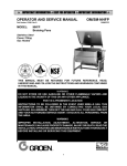
Equipment Description
Groen NHFP and NHFP(E) Gas Fired Braising
Pans provide a stainless steel pan equipped with
heat transfer fins, burner/combustion chamber,
power tilting mechanism, thermostatic controls,
and hinged cover. The Braising Pan serves as a
braising unit, griddle, fry pan, oven, kettle, bain
marie, or food warmer and server. It can also be
adapted for use as a steamer.
A fully enclosed, spring-type actuator
counterbalances the cover to keep it opened or
closed. The cover opens to the back and is
hinged to the frame, so that it moves
independently of the pan body.
Different ignition systems distinguish the basic
models. Model NHFP uses a thermopilecontrolled, standing pilot flame to light the main
burner. Model NHFP(E) ignites the main burner
directly with an electrically heated hot surface
igniter.
The pan body is constructed of heavy-duty
stainless steel welded into one solid piece, with a
polished interior and a semi-deluxe finish on the
exterior. A pouring lip is welded into the front
wall. The cooking surface is a stainless steel
clad plate fitted with welded heat transfer fins
that assure uniform heat transfer over the entire
surface. The gas burner/combustion chamber
supplies the heat.
The following models and options are available:
Model
Pan Body Dimensions, Inches
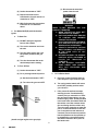
The pan is tilted forward by an electrically
powered actuator mechanism. A three-position
switch on the front of the control console gives
the operator positive, smoothly operating control
of tilting. When the pan is tilted, the burners shut
off automatically.
The thermostat provides automatic control of
cooking temperature. The thermostat dial on the
front of the control console turns the heat on or
off and sets the pan temperature.
4
OM-NHFP
Depth
Firing
Rate
NHFP-3
31¾
9
104,000
BTU/hr
NHFP(E)-3
31¾
9
104,000
BTU/hr
NHFP-4
41d
9
144,000
BTU/hr
NHFP(E)-4
41d
9
144,000
BTU/hr
Optional Equipment (Any Model)
1. Fill faucet with swing spout
2. Model REJ Steamer Insert
3. Caster mounting kit (factory installation
only)
4. Two inch tangent draw-off
A vented, heavy gauge, one-piece, stainless
steel cover with rear condensate drip shield on
its underside is standard on the Braising Pan.
Left to
Right
OM-NHFP
Inspection and Unpacking
Cut the straps holding the unit on the skid, and
lift the unit straight up off the skid.
The unit will arrive completely assembled,
wrapped in protective plastic on a heavy skid, in
a heavy cardboard carton. Immediately upon
receipt, inspect the carton for damage. Report
any apparent shipping damage or an incorrect
shipment to the delivery agent.
CAUTION
SHIPPING STRAPS ARE UNDER TENSION
AND CAN SNAP BACK WHEN CUT.
When installation is to begin, get someone to
assist in removing the carton. Lift it straight up
and away from the unit. Do not simply raise it
and push backwards - you will break the
cover assembly vent handle. Write down the
model number, serial number, and installation
date of your unit, and keep this information for
future reference. Space for these entries is
provided at the top of the Service Log in this
manual.
UNIT WEIGHS 500 TO 660 LB (230 TO 255
KG). FOR SAFE HANDLING, INSTALLER
SHOULD OBTAIN HELP AS NEEDED, OR
EMPLOY APPROPRIATE MATERIALS
HANDLING EQUIPMENT (SUCH AS A
FORKLIFT, DOLLY, OR PALLET JACKET)
TO REMOVE THE UNIT FROM THE SKID
AND MOVE IT TO THE PLACE OF
INSTALLATION.
Installation
The NHFP or NHFP(E) Braising Pan should be
installed in a ventilated room for efficient
performance. Items which might obstruct or
restrict the flow of air for combustion and
ventilation must be removed. The area directly
around the braising pan must be cleared of all
combustible material.
legs securely to the floor.
4.
Complete the piping to the gas service
by using 1/2 inch IPS pipe or approved
equivalent.
WARNING:
THIS UNIT IS FOR COMMERCIAL USE.
NEVER USE HOME OR RESIDENTIAL
GRADE GAS CONNECTIONS. THEY DO
NOT MEET GAS CODES AND COULD BE
HAZARDOUS.
WARNING
INSTALLATION OF THE BRAISING PAN
MUST BE DONE BY PERSONNEL
QUALIFIED TO WORK WITH GAS AND
ELECTRICITY. IMPROPER INSTALLATION
CAN RESULT IN INJURY TO PERSONNEL
AND/OR DAMAGE TO EQUIPMENT.
5. For a unit on casters, complete
connection to the gas supply with
connectors that comply with the
standard for Connectors for Moveable
Gas Appliances, ANSI Z21.69a-latest
edition. Restrain movement of the unit
by attaching a cable or chain to the
eyelet (provided at the back of the
frame) and anchoring the cable or chain
to the wall or floor. Make the length and
location of the cable such that the unit
cannot pull on the gas connection while
the cable is connected. The gas
connection must be made with a quick
disconnect device which complies with
ANSI Z21.41b - latest edition.
1. Installation on combustible floors is
allowed, with a minimum clearance to
combustible and noncombustible
construction of six inches at the rear,
two inches at the left, and zero inches at
the right.
2. Install the unit under a vent hood.
3. Level the unit by adjusting the bullet feet
or floor flanges on the legs. Make sure
the tilting mechanism has been run all
the way to the horizontal position. Check
levelness with a spirit level set on the
bottom of the pan body. Anchor the rear
5
OM-NHFP
OM-NHFP
8. In Canada, the installation must conform
to CAN/CGA B149, Installation Codes
for Gas Appliances and Equipment,
and/or local codes.
9. The braising pan and its shutoff valve
must be disconnected from the gas
supply piping system during any testing
at pressures in excess of ½ psig (3.48
kPa). The appliance must be isolated
from the gas supply piping system by
closing its individual manual shutoff
valve during any pressure testing of the
gas supply piping system at test
pressures equal to or less than ½ psig
(3.48 kPa).
WARNING
ELECTRICALLY GROUND THE UNIT AT THE
TERMINAL PROVIDED. FAILURE TO
GROUND UNIT COULD RESULT IN
ELECTROCUTION AND DEATH.
6. Provide 115 Vac, 60 Hz, 5 Amp
electrical service. Local codes and/or
National codes should be observed in
accordance with ANSI/NFPA70 - latest
edition. AN ELECTRICAL GROUND IS
REQUIRED. The Electrical Schematic is
located on the inside of the Service
Panel.
9. Space for servicing and operation is
required. DO NOT block any air intake
spacing to the combustion chamber or
obstruct air flow.
In Canada, provide electrical service in
accordance with the Canadian Electrical
Code, CSA-C22.1 Part 1, and/or local
codes.
10. After the pan has been connected to the
gas supply, check each gas joint for
leaks. Use a thick soap solution or other
suitable leak detector. Do not use a
flame to check for leaks.
7. The installation must conform with the
American National Standard Z223.1 latest edition National Fuel Gas Code.
The unit should be installed in an
adequately ventilated room with an
adequate air supply. The best ventilation
will use a vent hood and exhaust fan.
DO NOT obstruct the flue or vent.
Initial Start-Up
4. To shut down the unit, turn the
thermostat dial to "OFF".
Now that the Braising Pan has been installed,
you should test it to ensure that the unit is
operating correctly.
1. Remove all literature and packing
materials from the interior and exterior of
the unit.
WARNING
WATER IS EXTREMELY HOT AND CAN
CAUSE SEVERE BURNS. AVOID WATER
WHEN EMPTYING UNIT.
2. Put enough water into the pan to cover
the bottom to a depth of 1/4 to 1/2 inch.
With the tilting mechanism run to the
horizontal position, note how the water
lies in the pan, to confirm that the pan
was leveled properly during installation.
5. Press the power tilt switch down to pour
out the water and to confirm that the pan
body can be tilted from horizontal to
vertical. Pull the switch up to lower the
pan.
3. Following "To Start Pan" instructions for
your pan model, begin heating the water
at a thermostat setting of 235oF. At this
setting, heating should continue until the
water boils.
If the unit functions as described above, it is
ready for use. If it does not, contact your local
Groen Authorized Service Agency.
6
OM-NHFP
OM-NHFP
A. Controls
Operation
Operator controls for the Braising Pans are:
1. The thermostat dial, located on the
control console to the right of the pan
body. This dial is used to turn the
thermostat on or off and to set the
thermostat for pan temperatures between
175o and 425oF.
2. The power tilt switch, also located on the
control console, which is used to raise or
lower the pan body
3. The main supply gas cock, installed on
the gas line to the unit.
4. For NHFP only, the manual valve on the
Combination Gas Control Valve, which is
located under the pan on the gas line to
the burner manifold. This valve selects
settings of "OFF", "PILOT", or "ON" for
the Combination Control.
Control for Thermopile System — Model NHFP
(b) Open the main supply gas
cock.
(c) Tilt the pan, so the pilot
burner is easier to reach.
B. Operating Procedure
(d) Hold a lighted match at the
pilot burner, while you
depress the knob on the
Combination Control and turn
it counterclockwise to the
"PILOT" position. Continue to
hold the knob down for 60
seconds.
WARNING
KEEP THE APPLIANCE AREA FREE AND
CLEAR OF COMBUSTIBLE MATERIALS.
CAUTION
BE SURE ALL OPERATORS READ,
UNDERSTAND AND FOLLOW THE
OPERATING INSTRUCTIONS, CAUTIONS
AND SAFETY INSTRUCTIONS CONTAINED
IN THIS MANUAL.
(e) Release the knob. The pilot
flame should stay lighted.
(f) Turn the knob
counterclockwise to "ON".
KEEP FLOORS IN BRAISING PAN WORK
AREA CLEAN AND DRY. IF SPILLS OCCUR,
CLEAN IMMEDIATELY TO AVOID THE
DANGER OF SLIPS OR FALLS.
(3) Turn the thermostat dial to the
desired temperature.
1. For Model NHFP with Thermopile System
b. To Shut Off Pan
a. To Start Pan
(1) Set the thermostat dial to "OFF".
(1) Set thermostat to "OFF".
(2) To turn off the gas pilot, depress
the knob on the Combination
Control and turn it clockwise to
"OFF".
(2) Light gas pilot.
(a) Set knob on Combination Gas
Control Valve to "OFF" by
depressing the knob slightly
and turning it clockwise.
c. To Relight Pilot
(1) Close the main supply gas cock.
7
OM-NHFP
OM-NHFP
(c) Disconnect the electrical
power from the unit.
(2) Set the thermostat to "OFF".
(3) Depress the knob on the
Combination Control and turn it
clockwise to "OFF".
(4) Wait 5 minutes, then proceed as
instructed at "To Start Pan"
above.
WARNING
WHEN TILTING BRAISING PAN FOR
PRODUCT TRANSFER:
1) WEAR PROTECTIVE OVEN MITT
AND PROTECTIVE APRON.
2) USE CONTAINERS DEEP ENOUGH
TO CONTAIN AND MINIMIZE
PRODUCT SPLASHING
3) PLACE CONTAINER ON A STABLE,
FLAT SURFACE, AS CLOSE TO THE
BRAISING PAN AS POSSIBLE.
4) STAND TO THE SIDE OF THE PAN
WHILE POURING — NOT DIRECTLY
IN THE POUR PATH OF HOT
CONTENTS.
5) RETURN PAN BODY TO UPRIGHT
POSITION AFTER CONTAINER IS
FILLED OR TRANSFER IS
COMPLETE.
6) DO NOT OVERFILL CONTAINER.
AVOID DIRECT SKIN CONTACT
WITH HOT CONTAINER AND
CONTENTS
2. For Model NHFP(E) with Hot Surface
Igniter
a. To Start Pan
(1) DO NOT attempt to light the
burner with a flame.
(2) Turn on the electrical service to
the unit.
(3) Turn the main supply gas cock
ON (handle parallel to the gas
pipe).
(4) Turn the thermostat dial to the
desired temperature setting.
b. To Turn Off Pan
(1) Set the thermostat to "OFF".
3. To Tilt Either Model
(2) For a prolonged shut-off period:
a. Press the power tilt switch down to
raise the pan or up to lower the pan.
(a) Set the thermostat to "OFF".
(b) Turn the main gas cock OFF
b. The spring loaded switch will return
to the OFF (middle) position when
you release it.
(handle at right angles to the gas pipe).
8
OM-NHFP
c. If the power tilt mechanism stops
working (see the Troubleshooting
section) and you must raise or lower
the pan body without delay, you can
tilt the body by hand. Fit the provided
hand crank onto the slotted shaft end
that sticks out of the actuator motor
(the end facing the front of the unit).
Turn the crank clockwise to lower the
pan or counterclockwise to raise the
pan. It may take several minutes to
crank the pan to the desired position,
but the operation can be speeded up
by substituting a reversible electric
drill with screwdriver bit in place of
the hand crank.
OM-NHFP
4. To Move a Unit on Casters
2. Leave the cover vent open to let excess
steam escape. For long simmering
operations, you may wish to close the
vent.To check cooking progress when
the cover has been closed, grasp the
plastic handle of the vent cover, lift it
slightly, and move it quickly to either
side.
The unit must be anchored with a cable
or chain to avoid accidentally breaking or
pulling loose the gas connection. When
the unit is to be moved, first turn off and
disconnect the gas connection.
Disconnect the cable from its anchor
point on the floor or wall. Anchor the
unit again as soon as it is in its new
operating location or returned to the
previous location. Turn on the gas
supply and check for leaks with a soap
solution. If leaks are found do not
operate the equipment. Call for service.
2. Standing to one side of the pan (to avoid
the steam that will be released) grasp the
nearer corner of the cover handle and
raise the cover. The cover will stay in the
open position until you push it down.
4. To pour or dump product, remove
grease, or assist cleaning, first raise the
cover, then tilt the pan up and forward by
pressing down on the power tilt switch.
When you release the switch, the pan
body will hold its position.
5. To Preheat the Pan
a. For best braising or frying results,
preheat pan before you put in any
food.
b. To get an even temperature across
the pan, preheat at a setting of 300oF
or less for 15 minutes or through
several on-off cycles of the burner.
WARNING
IF THE PAN CONTAINS ITEMS IN SAUCE OR
MELTED FAT, THEY CAN SLIDE FORWARD
SUDDENLY DURING TILTING AND SPLASH
OUT THE HOT LIQUID.
WARNING
DO NOT HEAT AN EMPTY PAN FOR MORE
THAN FIVE MINUTES AT A SETTING
HIGHER THAN 300oF. DAMAGE TO THE
PAN COULD RESULT.
C.
D.
Cleaning
After each use, turn the thermostat to "OFF"
and clean all food-contact surfaces to
maintain proper sanitation. At the end of
each day or at least once every 12 hours,
turn off the heat and shut off the electric
power to the unit, then clean both the interior
and the exterior of the pan. See page 11 for
cleaning instructions.
Cooking
1. To simmer or slowly heat an item, set the
dial at about 210oF or lower. Put the
cover down to keep moisture loss at a
minimum, or leave the cover up to help
dry the product. Set the thermostat
higher to cook or drive off moisture
faster. You may adjust the thermostat to
any setting in the thermostat range to
cook the item exactly as required.
Sequence of Operation
The following "action-reaction" outline is provided to help the user understand the functioning of
the equipment.
A. Model NHFP
burner. Depressing the knob in this
position overrides the automatic control,
which otherwise shuts off the gas supply
when the thermopile is cold.
When the operator presses down the
knob on the Combination Gas Control
Valve and turns it to "PILOT", gas from
the supply line is admitted to the pilot
Lighting and maintaining the pilot flame
9
OM-NHFP
OM-NHFP
for sixty seconds heats the thermopile to
operating temperature, so the thermopile
begins to provide electric current at 750
millivolts. Electricity from the thermopile
powers the control circuit and the
Combination Gas Control Valve. When
the thermopile begins operating at full
capacity, the knob may be released.
The thermostat controls heating by
alternately calling for flames at the full
capacity of the main burner and then
signaling the control to shut the burner
off completely.
Because the control works in this "all or
nothing" manner, the pan heats as fast
as it can until it reaches the set
temperature, no matter what that
temperature is. Turning the thermostat
dial to a higher setting will cause heating
to continue longer, until the pan reaches
the higher temperature, but it cannot
make the pan heat any faster.
When the knob is turned "ON", the
automatic valve for the main burner
becomes able to open. Setting the
thermostat causes a signal to be sent to
the valve, which opens and admits gas to
main burner. Gas from the main burner is
ignited by the pilot flame. When the pan
reaches the set temperature, the
thermostat switch opens, stopping the
signal to the main burner valve.
The pans are protected from overheating
by the high-limit thermostat. If the pan
temperature rises above 425oF, the highlimit thermostat causes the automatic
gas control valve to close. When the pan
cools, the thermostat automatically
resets and permits normal operation to
continue.
This causes the valve to close. When the
pan cools below the set temperature, the
thermostat switch closes and starts
another heating cycle. On-off cycling
continues and maintains the pan at the
set temperature.
The power tilt switch controls a
reversible motor that drives a ball screw
mechanism. When the switch is held in
the lowered position, the mechanism
raises the pan body. The body rests on
trunnions near the front corners, so it
tilts forward until the switch is released
or the body reaches the vertical limit. Any
time the pan is tilted more than ten
degrees from the horizontal, a tilt limit
switch automatically turns off the gas
flow to the main gas burner.
B. Model NHFP(E)
When the operator sets the desired
temperature on the thermostat dial, the
thermostat switch closes and causes
electric current to heat the Hot Surface
igniter. When the igniter gets hot enough
to ignite gas, a sensor built into the
electronic module signals the automatic
gas control valve, which admits gas to
the burner. Gas flowing from the burner
is ignited directly by the igniter. A
separate sensor detects flame at the
burner and sends a signal that turns off
electric power to the igniter. If flame is
not sensed within 30 seconds, a timer
shuts off the gas flow.
If the tilting motor gets too hot during
operation, an overheat protection switch
will open and stop the motor. When the
motor cools sufficiently, the switch will
reset automatically and permit tilting to
begin again.
When the pan reaches the set
temperature, the thermostat switch
opens, stopping the signal to the gas
control valve and causing the valve to
close. When the pan cools below the set
temperature, the thermostat switch
closes and starts another heating cycle.
On-off cycling continues and maintains
the pan at the desired temperature.
C. Both Models
10
10 OM-NHFP
OM-NHFP
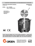
Cleaning
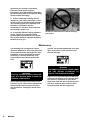
abrasive materials or metal implement that
might scratch the surface, because scratches
make the pan hard to clean and provide
places for bacteria to grow. Do NOT use steel
wool, which may leave particles imbedded in
the pan surface and cause eventual
corrosion and pitting.
WARNING
KEEP WATER AND SOLUTIONS OUT OF
CONTROLS AND BURNERS. NEVER SPRAY
OR HOSE THE CONTROL CONSOLE OR
ELECTRICAL CONNECTIONS.
5. As part of the daily cleaning program,
clean all external and internal surfaces that
may have been soiled. Remember to check
such parts as the underside of the cover,
control console, etc.
1. Before any cleaning operation, shut off
the burner by turning the thermostat dial to
"OFF". If water or cleaning solution will be
sprayed, unplug the unit from the electric
power source, or shut off the power at the
circuit breaker or fuse panel.
6. Controls and the control console may be
cleaned with a damp cloth.
2. Clean all food-contact surfaces soon
after use, before the pan has cooled
completely. If the unit is in continuous use,
thoroughly clean and sanitize both interior
and exterior at least once every 12 hours.
WARNING
THE CONTROL BOX IS NOT WATERPROOF. TAKE CARE TO KEEP WATER AND
CLEANING SOLUTIONS OUT OF THE BOX.
NEVER HOSE OR SPRAY ELECTRICAL
CONTROLS, CONNECTIONS OR CONTROL
CONSOLE.
CAUTION
MOST CLEANERS ARE HARMFUL TO THE
SKIN, EYES, MUCOUS MEMBRANES AND
CLOTHING. PRECAUTIONS SHOULD BE
TAKEN TO WEAR RUBBER GLOVES,
GOGGLES OR FACE SHIELD AND
PROTECTIVE CLOTHING. CAREFULLY
READ THE WARNINGS AND FOLLOW THE
DIRECTIONS ON THE LABEL OF THE
CLEANER TO BE USED.
7. Exterior surface of the unit may be
polished with a recognized stainless steel
cleaner, such as "Zepper" from Zep
Manufacturing Co.
8. If the equipment needs to be sanitized,
use a sanitizing solution equivalent to one
that supplies 200 parts per million available
chlorine. Obtain advice on the best sanitizing
3. Scrape or rinse out large amounts of
food residues, then wash the inside of the
pan body with a mixture of hot water and
soap or an appropriate detergent, such as
Mikro-Quat from ECOLAB. Follow the
detergent supplier's recommendations on
strength of the solution to use. Rinse the pan
thoroughly with hot water and drain
completely.
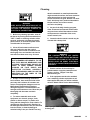
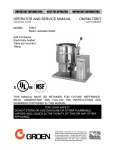
4. To remove materials stuck to the
equipment, use a brush, sponge, cloth,
plastic or rubber scraper, or plastic wool
along with the detergent or soap solution. To
minimize the effort required in washing, let
the detergent solution sit in the pan and soak
into the residue, or heat the detergent
solution briefly in the pan. Do NOT use any
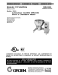
Use a sponge, cloth or plastic brush to clean the
braising pan.
11
OM-NHFP
11
OM-NHFP
agent from your supplier of sanitizing
products. Following the supplier's
instructions, apply the sanitizing agent after
the unit has been cleaned and drained. Rinse
off the sanitizer thoroughly.
9. If there is difficulty removing mineral
deposits or a film left by hard water or food
residues, clean the pan thoroughly and then
use a deliming agent, like Lime-Away from
ECOLAB, in accordance with the
manufacturer's directions. Rinse and drain
the unit before further use.
10. If especially difficult cleaning problems
persist, contact your cleaning product
representative for assistance. The supplier
has a trained technical staff with laboratory
facilities to serve you.
Scrapers or steel wool can harm the braising
pan surface.
Maintenance
Your Braising Pan is designed to require
minimum maintenance, but certain parts may
need replacement after prolonged use. After
installation, no user adjustment should be
necessary. If a service need arises, only
authorized personnel should perform the
work.
console, and possible adjustment of the pilot
light. At least twice a year, grease the two
trunnion bearings.
WARNING
DISCONNECT ELECTRICAL POWER FROM
THE UNIT BEFORE ATTEMPTING TO
GREASE THE TRUNNION BEARINGS.
WARNING
ELECTRIC POWER ALWAYS SHOULD BE
SHUT OFF BEFORE WORK IS DONE ON
INTERNAL COMPONENTS.
A Service Log is provided with the warranty
information at the back of this manual. Each
time service is performed on your Groen
equipment, enter the date on which the work
was done, what was done, and who did it.
Keep the manual with ther equipment.
Service personnel should check the unit at
least once a year. This periodic maintenance
should include inspecting electrical wires
and connections, cleaning the inside of the
control
12
12 OM-NHFP
OM-NHFP
Troubleshooting
Your Groen Braising Pan will operate smoothly and efficiently if properly maintained. However, the
following is a list of checks to make in the event of a problem. If the actions suggested do not
solve the problem, call your qualified Groen Service Representative. For the phone number of the
nearest agency, call your area Groen representative or the Groen Parts and Service Department. If
an item on the list is followed by • , the work should only be performed by a qualified service
representative.
WARNING
BEFORE REPLACING ANY PARTS, DISCONNECT THE UNIT FROM THE ELECTRICAL POWER
SUPPLY AND CLOSE THE MAIN GAS COCK. ALLOW FIVE MINUTES FOR UNBURNED GAS TO
VENT.
USE OF ANY REPLACEMENT PARTS OTHER THAN THOSE SUPPLIED BY GROEN OR THEIR
AUTHORIZED DISTRIBUTORS CAN CAUSE INJURY TO THE OPERATOR AND DAMAGE TO THE
EQUIPMENT AND WILL VOID ALL WARRANTIES.
IMPORTANT:
Service performed by other than factory authorized personnel will void all
warranties.
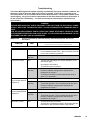
SYMPTOM
A.
WHAT TO CHECK
WHO
• indicates items which must be performed by an authorized technician.
All Models
Pan will not tilt
Burners will not light
User
a.
b.
That electrical power supply is on.
For overheated actuator motor. Wait 15 minutes for motor
to cool, then operate the power tilt.
Auth Service
Rep Only
c.
For burned out capacitor or motor.•
User
a.
That the main gas supply cock is open (handle is in line
with the gas pipe)
Gas supply to the building.
That the pan body is horizontal.
b.
c.
Auth Service
Rep Only
d.
e.
Pan continues to heat
after it reaches desired
temperature
Thermostat operation. The thermostat should click when
the dial is rotated to settings above and below the
temperature of the pan.•
That the tilt limit switch is closed when the pan body is
within 10o of horizontal.•
User
a.
Thermostat dial setting
Auth Service
Rep Only
b.
c.
Thermostat calibration.•
Thermostat operation. The thermostat should click when
the dial is rotated to settings above and below the
temperature of the pan.•
Pan stops heating
User
before reaching desired
Auth Service
temperature.
Rep Only
a.
Thermostat dial setting.
b.
c.
Thermostat calibration.•
Thermostat operation. The thermostat should click when
the dial is rotated to settings above and below the
temperature of the pan.•
Pan heats unevenly
a.
b.
That the pan body is horizontal.
That the pan is preheated properly in accordance with the
instructions in the Operation section of this manual.
User
13
OM-NHFP
13
OM-NHFP
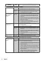
SYMPTOM
B.
WHAT TO CHECK
WHO
• indicates items which must be performed by an authorized technician.
Model NHFP with Thermopile Ignition System
Pilot will not light.
Pilot flame goes out
when Combination
Control knob is
released.
User
a.
Lighting procedure, to ensure that the instructions in the
Operation section of this manual are followed
Auth Service
Rep Only
b.
c.
d.
That the pilot gas supply line is purged of air.•
Pilot gas adjustment screw, to ensure that it is open.•
Pilot tubing and orifice for clogging.•
Auth Service
Rep Only
a.
b.
Pilot gas adjustment.•
That electrical connections from Powerpile generator to
Pilotstat power unit and to Powerpile operator are clean
and secure.•
Open and closed circuit output voltages of the generator
against the Acceptable Range Charts in the manual for the
W720 Systems Tester.•
Resistance of the Pilotstat power unit.•
If an appropriate meter is not available, replace first the
generator, than the power unit.•
c.
d.
e.
Pan will not heat, and
pilot light is out
User
a.
b.
Auth Service
Rep Only
c.
d.
e.
Pan will not heat, but
pilot light is burning.
C.
Auth Service
Rep Only
a.
That the knob on the Combination Gas Control Valve is in
the "ON" position.
Pilot tubing and orifice for clogging.
That electrical connections from Powerpile generator to
Pilotstat power unit and to Powerpile operator are clean
and secure.•
Open and closed circuit output voltages of the generator
against the Acceptable Range Charts in the manual for the
W720 Systems Tester.•
If an appropriate meter is not available, replace the
generator.•
That high-limit thermostat switch is closed.•
Model NHFP(E) with Hot Surface Ignition System (Refer to Schematic)
Burner does not come
on, and glow coil does
not heat.
User
a.
That electric power is being supplied to the unit.
Auth Service
Rep Only
b.
c.
d.
For 115V input to the control module.•
For a 24V supply at the transformer.•
For 24V between pins "2" and "4" of the control module. If
not present, check the thermostat/high-limit circuit for open
thermostat switches .•
Voltage of supply to the igniter by removing the igniter plug
from the receptacle of the control module and reading
voltage across the pins of the igniter receptacle. If 115V is
present, replace the igniter. If 115V is not present, replace
the control module.•
Voltage across the terminals of the main gas valve
solenoid. If 24 VAC is present, replace the gas valve
assembly. If not, replace the control module.•
e.
f.
14
14 OM-NHFP
OM-NHFP
SYMPTOM
WHAT TO CHECK
WHO
Burner does not come Auth Service
on, but the igniter heats. Rep Only
• indicates items which must be performed by an authorized technician.
a.
b.
c.
d.
e.
Voltage across the terminals of the gas valve solenoids. If
24 VAC is present, replace the gas valve assembly. If not,
replace the control module.•
Ground connection of module terminal "12" (green wire) for
firm attachment.•
Flame sensing probe and wire "11" (blue) for a short to
ground. If necessary, correct the short or replace the
probe.•
For a short to ground at 24V source. If the transformer is
shorted, remove the short and replace the control
module.•
After the transformer has been replaced, check the flame
sensing function. If flame sensing is not working, reverse
the leads of either the 115V or 24V side of the control
transformer.•
CAUTION
USE OF ANY REPLACEMENT PARTS OTHER THAN THOSE SUPPLIED BY GROEN OR THEIR
AUTHORIZED DISTRIBUTOR CAN CAUSE INJURY TO THE OPERATOR AND DAMAGE TO THE
EQUIPMENT AND WILL VOID ALL WARRANTIES.
15
OM-NHFP
15
OM-NHFP
16 OM-NHFP
16
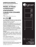
Parts List
OM-NHFP
Parts List
To order parts, contact your authorized Groen Service Agency. Supply the model designation, part description, part
number, quantity, and, where applicable, voltage and phase.
Key
Description
Part No.
Key
Description
Part No.
Igniter, 24V
088254
Ignition Control 24V
088253
Bracket
066013
Actuator Cover
014085
3
Spring
012533
4
Cover Assembly, Vent
017494
*
*
*
5
Actuator Assembly - Gray Motor/Gray Shaft 132413
25
Flame Sensing Probe
003328
5
Actuator Assembly - Black Motor/Silver Shaft 045880
26
Thermostat Knob
003908
6
Capacitor
099243
27
Actuator Motor
054716
—
Capacitor Box Enclosure
049068
*
Actuator Motor Bracket
049904
7
Crank, Manual, Actuator
050242
28
Support Pin
056909
8
Burner, Pilot, Natural Gas
001125
29
Transformer
074839
9
Burner, Pilot, Propane Gas
001129
30
Orifice Igniter Tube
see table
10
Thermopile
001126
31
Runner Tube, Size 2
073190
11
Joint, Swivel, ½ NPT
076680
31
Runner Tube, Size 3
055008
12
Valve Ctrl Nat Gas Standing Pilot
002648
31
Runner Tube, Size 4
046406
13
Valve Ctrl Propane Standing Pilot
002649
32
Box
050378
14
Valve Ctrl Nat Gas Carb Ignition
049555
Spacers
012733
15
Valve Ctrl Propane Carb Ignition
049557
Back Panel, Size 3
054678
16
Valve, Manual Gas Shut-off
005429
Back Panel, Size 4
054679
*
*
Combustion Chamber, Complete
050381
Casters
049279
Lower Combustion Chamber
070152
*
*
*
*
*
Casters
049280
17
Switch, Toggle
002664
18
Tilt Switch
007517
19
Thermostat, High-limit
013481
20
Thermostat, Operating
041700
Three Pan, Natural Gas
101622
21
Nat Gas Jet Main Burner
045897
Four Pan, Natural Gas
101621
22
Propane Jet Main Burner
050047
Three Pan, Propane Gas
101624
23
Hot Surface Igniter 115V
054285
Four Pan, Propane Gas
101623
24
Hot Surface Ignition Control Unit
088252
1, 2
ORIFICE IGNITER TUBE
*Not Shown
17
OM-NHFP
17
OM-NHFP
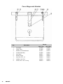
Cover Hinges and Actuator
Key
Part No.
Description
OM-NHFP
Size 4 Pan
1
Stud-Weld
012590
012590
2
Hinge, Cover
013485
013485
3
Bracket, Cover Attachment
013277
013277
4
Actuator Assembly
014085
014085
5
Nut, Dome
005471
005471
6
Bracket, Hinge
054876
004556
7
Nut, Hex, 5/16 - 18
003823
003823
8
Washer, Lock 5/16
005656
005656
9
Screw, 5/16 - 18 x ¾” Long
006014
006014
18
18 Size 3 Pan
OM-NHFP
Model NHFP(E) with Electronic Coil Ignition
Wiring Diagram for units built before May, 1991
Wiring Diagram for units built after April, 1991
19
OM-NHFP
19
OM-NHFP
Model NHFP with Standing Pilot
Wiring Diagram
Carborundum Igniter Assembly
20
20 OM-NHFP
OM-NHFP
References
American Gas Association Laboratories
8501 East Pleasant Valley Rd.
Cleveland, Ohio 44131
Z223.1-1984
National Fire Protection Association
60 Battery March Park
Quincy, Massachusetts 02269
National Fuel Gas Code
NFPA/54
American National Standards Institute
1403 Broadway
New York, New York 10018
NFPA/70
NFPA/96
Installation of Gas Appliances &
Gas Piping
The National Electrical Code
Ventilating Hoods
National Sanitation Foundation
3475 Plymouth Road
Ann Arbor, Michigan 48106
Canadian Gas Association
55 Scarsdale Road
Don Mills, Ontario M3B 2 R3
Underwriters Laboratories, Inc.
333 Pfingsten Road
Northbrook, Illinois 60062
ECOLAB, INC.
370 Wabasha
St. Paul, Minnesota 55102
ZEP Manufacturing
1390 Lunt Avenue
Elk Grove Village, Illinois 60007
21
OM-NHFP
21
OM-NHFP
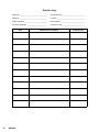
Service Log
Model No. ______________________________
Purchased From _________________________
Serial No. ______________________________
Location _______________________________
Date Purchased _________________________
Date Installed ___________________________
Purchase Order No. ______________________
For Service Call _________________________
Date
Maintenance Performed
22
22 OM-NHFP
Performed by
OM-NHFP
Warranty
Limited Warranty
To Commercial Purchasers *
(Domestic U.S., Hawaii &
Canadian Sales Only)
Groen Foodservice Equipment ("Groen Equipment") has been skillfully manufactured, carefully inspected and
packaged to meet rigid standards of excellence. Groen warrants its Equipment to be free from defects in
material and workmanship for (12) twelve months with the following conditions and subject to the following
limitations.
I.
This parts and labor warranty is limited to Groen Equipment sold to the original commercial
purchaser/users (but not original equipment manufacturers), at its original place of installation in the
continental United States, Hawaii and Canada.
II. Damage during shipment is to be reported to the carrier, is not covered under this warranty, and is
the sole responsibility of purchaser/user.
III. Groen, or an authorized service representative, will repair or replace, at Groen's sole election, any
Groen Equipment, including but not limited to, draw-off valves, safety valves, gas and electric
components, found to be defective during the warranty period. As to warranty service in the territory
described above, Groen will absorb labor and portal to portal transportation costs (time & mileage)
for the first twelve (12) months from date of installation or fifteen (15) months from date of shipment
from Groen.
IV. This warranty does not cover boiler maintenance, calibration, periodic adjustments as specified in
operating instructions or manuals, and consumable parts such as scraper blades, gaskets, packing,
etc., or labor costs incurred for removal of adjacent equipment or objects to gain access to Groen
Equipment. This warranty does not cover defects caused by improper installation, abuse, careless
operation, or improper maintenance of equipment. This warranty does not cover damage caused by
poor water quality or improper boiler maintenance.
V. THIS WARRANTY IS EXCLUSIVE AND IS IN LIEU OF ALL OTHER WARRANTIES, EXPRESSED
OR IMPLIED, INCLUDING ANY IMPLIED WARRANTY OF MERCHANTABILITY OR FITNESS FOR
A PARTICULAR PURPOSE, EACH OF WHICH IS HEREBY EXPRESSLY DISCLAIMED. THE
REMEDIES DESCRIBED ABOVE ARE EXCLUSIVE AND IN NO EVENT SHALL GROEN BE LIABLE
FOR SPECIAL, CONSEQUENTIAL OR INCIDENTAL DAMAGES FOR THE BREACH OR DELAY
IN PERFORMANCE OF THIS WARRANTY.
VI. Groen Equipment is for commercial use only. If sold as a component of another (O.E.M.)
manufacturer's equipment, or if used as a consumer product, such Equipment is sold AS IS and
without any warranty.
* (Covers All Foodservice Equipment Ordered After October 1, 1995)
23
OM-NHFP
23
1055 Mendell Davis Drive • Jackson MS 39272
888-994-7636 • 601-372-3903 • Fax 888-864-7636
groen.com
PART NUMBER 121010 REV. B (10/07)