1
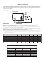
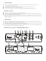
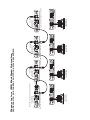
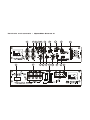
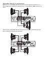
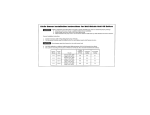
Power Amplifier
Instruction Manual
To ensure maximum performance and safety,
please follow this manual. Please retain the
manual for future reference after installation
Models: SPACEBS4 -V1
DSPACEBB1-V1
www.vibeaudio.co.uk
OWNERS MANUAL
Congratulations on purchasing your VIBE
amplifier, please read this manual in order
to fully understand how to get the best
results from your amplifier and ensure
that all advice on how to look after the
amplifier is followed.
Thank you for buying VIBE, we hope you
enjoy listening to your product as much as
we enjoyed creating it.
VIBE R&D Division
Attention
An aftermarket audio amplifier will place an additional load on the vehicles charging system, most modern vehicles have
sufficient capacity in the charging system as not all the electrical components of the vehicle will be switched on at once. Check
the fuse rating of the amplifier and use this as the peak current requirement, generally the continuous current draw will be a
third of the peak current, in other words an amplifier fused at 30 amps will have a continuous current draw of 10 amps when
playing music, however it may peak at 30 amps on occasions. Please check with the manufacturer as to whether your vehicle
can cope with the additional load of your amplifier, in some instances it may be necessary to upgrade the alternator and battery
or risk damage to the vehicles electrical system.
Mounting Guidelines
Your VIBE amplifier is designed with a swift installation routine in mind. Please mount the amplifier in a dry location on a solid
surface. NEVER mount the amplifier upside down, this will cause the amplifier to over heat and will eventually damage the
amplifier. Before fixing the amplifier in place please ensure that there is sufficient air flow around the exterior of the casing,
at least two inches is sufficient.
Connections
Power Cable
●
●
●
●
●
At least 4 gauge cable (Deep SpaceBox Bass 1) 8 gauge cable ( SpaceBox Stereo 4) should be used for the
power connection to the amplifier.
The power cable should be taken directly from the battery. Rubber grommets should be used when passing through
any bulkheads to prevent the cable from becoming chaffed or cut.
It is vital that a fuse / circuit breaker (of at least equal value to the one fitted on the amplifier) is placed inline with the
power cable and is no further than eighteen inches away from the battery.
Please ensure that the fuse is not fitted until the entire installation procedure is complete.
The two tables below are to help you decide on what cable is correct for you. The first enables you to select the size of
cable depending on the length required. The second will help you convert the cable size from American Wire Gauge to
Metric and Imperial if you need to.
Current demand
0–20 amps
20–35 amps
35–50 amps
50–65 amps
65–85 amps
85–105 amps
105–125 amps
125–150 amps
0 – 4 Ft
14
12
10
8
6
6
4
2
AWG Number
0
1
2
3
4
5
6
7
8
9
10
4 – 7 Ft
12
10
8
8
6
6
4
2
7 – 10 Ft
12
8
8
6
4
4
4
2
Length of Run
10 – 13 Ft
10
8
6
4
4
2
2
0
13 – 16 Ft
10
6
4
4
2
2
0
0
AWG to Metric and Imperial Conversion Chart
cross sectional area
Inch
mm
0.325
0.289
0.258
0.229
0.204
0.182
0.162
0.144
0.128
0.114
0.102
8.25
7.35
6.54
5.83
5.19
4.62
4.11
3.66
3.26
2.91
2.59
16 – 19 Ft
8
6
4
4
2
2
0
0
19 – 22 Ft
8
6
4
4
2
2
0
0
mm2
53.5
42.4
33.6
26.7
21.1
16.8
13.3
10.5
8.36
6.63
5.26
22 – 28 Ft
8
4
4
2
0
0
0
0
Ground Cable
●
●
●
●
At least 4 gauge cable (Deep SpaceBox Bass 1) 8 gauge cable ( SpaceBox Stereo 4) should be used for
the ground connection to the amplifier.
The amplifier ground should be connected directly to the chassis of the vehicle, to bare metal.
The cable length should be kept to an absolute minimum.
It is not recommended that you connect the ground cable to the vehicles seatbelts anchor point.
Remote Turn On
●
●
●
A minimum of 18 gauge cable should be used for this connection.
The cable should be run with exactly the same care and attention as the power cable and taken back to the source
(headunit) and joined to the remote cable provided.
If the source (headunit) does not have a remote turn on cable then a 12v supply should be used. This will require a
switch to be fitted inline to enable the amplifier to be turned on and off. Remember that if this switch is left on you will
flatten the car battery.
RCA Cables
●
●
●
Depending on the model number of your amplifier and the number of speakers you wish to power you will have to run
either one or two RCA cables from the source to the amplifier.
Please take extra care when running these cables from the source to the amplifier. Ensure that they are placed away
from all items that can generate any interference, wiring harnesses etc.
It is recommended that the RCA cables should be run on opposite sides of the car to the previously installed power
cables if possible, to avoid the cable picking up interference.
Terminals and controls : Deep SpaceBox Bass 1
5
12
7
11
15
9
8
6
4
10
14
3
2
13
1
1.
Low level input
For connection to any source (head unit) with a low level output. This is your RCA output from the source (headunit)
2.
Slave input / output
RCA input and output Connections used for amplifier strapping
3.
High level input
To be used when no RCA's are available. Use the provided loom and connect to the closest speaker. The loom connector will only fit one
way around. Once plugged in you should connect the wires as below:
Left Positive – L+ white
Left Negative - L- white / Black
Right Positive - R+ Grey
Right Negative - R- Grey / Black
4.
Gain control
Used to match the input signal of the source to the amplifier. See the setup section for more details.
5.
Subsonic filter control
This control allows the subsonic filter frequency to be set, the filter is adjustable from 10Hz to 80 Hz
6.
Crossover frequency control
This control is used to set the crossover point for the amplifier.
The frequency ranges on the low pass filter are from 30 Hz to 250 Hz,
7.
Bass boost frequency control
This control sets the frequency that will be boosted by the bass boost control, the frequency ranges from 30Hz to 125Hz
8.
Bass boost control
This control provides up to an extra +15 dB of bass boost at the chosen frequency. Use this boost to increase bass output from the
amplifier.
9.
Phase switch
This allows the phase of the amplifier to be set to 0 or 180 degrees, one setting will make the bass from the subwoofer sound more in
time with the front speakers.
10. Source switch
This switch is set according to amplifier application, in normal operation it should be set to NORMAL and if the amplifier is acting as a
slave in a strapped configuration it should be set to SLAVE IN.
11. Gain remote Input Jack
Use to plug in the remote supplied bass level controller BBR1.
12. Indicator LED
When the amplifier is operating correctly the LED will flash 3
times and then illuminate constant red.
When the amplifier is in protection mode the LED will flash to
indicate protection condition - see table for fault code diagnosis.
13. Power connections
See Connections section for details on correct connections.
14. Fuses
Please ensure the following fuse rating is used when replacing fuses: 30 amp x 4
15. Speaker terminal output
For connection to the speakers. See Application section for wiring examples.
Set Up Section
To correctly set the gain control of the amplifier to match that of the source (headunit) use the following setup routine:
Turn the gain control to minimum on the amplifier.
Ensure the bass boost is set to 0 dB.
On the headunit set all crossovers ( if applicable) to flat and both bass and treble to zero.
Turn up the source (headunit) to approx 3/4 volume.
Very slowly turn up the gain on the amplifier until distortion can be heard in any of the speakers or until the volume reaches
an uncomfortable listening level when this is reached turn down the gain control slightly.
The gain control is now set.
The setting of the crossover will depend on what kind of speaker you are installing.
For a subwoofer it is recommended that the crossover is set to Low Pass and the frequency is set to match that of the
speakers specifications, or your preferred frequency - this is usally about 60 - 120
For a pair of full range speakers it is recommended that the crossover is set to Flat. The two frequency controls will then
have no effect on the amplifiers output and the speaker will receive a full range signal. However, using the high pass
crossovers will allow more control of your speakers. By removing the bass (low frequencies) the speakers can perform at
higher volumes with less distortion.
Note:
By using the crossovers correctly you will not only lengthen the life of your speakers but you will also get better performance
from them. To optimise your setup seek the advise of a professional installation engineer or visit your local VIBE audio dealer.
Amp strapping
The VIBE Deep SpaceBox Bass 1 amplifier is capable of being strapped together to deliver the combined output of both amplifiers into
a single channel.
NOTE: only identical amplifiers may be strapped together.
Strapping procedure
·
Connect the RCA input from the source unit to the left and right RCA input of the master amplifier.
·
Connect a mono RCA lead between the SLAVE OUT output of the master amplifier and the SLAVE IN input
·
Set the source switch of the master amplifier to normal
·
Set the source switch of the slave amplifier to slave in
·
Set the phase switch of the master amplifier to 0 degrees
·
Set the phase switch of the slave amplifier to 180 degrees
·
Connect speaker cable between the negative speaker output of the master amp and the negative speaker output of the slave
amplifier. The cable must be of the same gauge you will be using to connect the amplifiers to the subwoofer
·
The master positive speaker output is to be connected to the subwoofer positive terminal
·
The slave positive speaker output is to be connected to the subwoofer negative terminal
MASTER AMP CONTROLLING MULTIPLE SLAVE AMPS
SET TO NORMAL
SET TO 0
MASTER AMP
INPUT
SLAVE AMP
SET TO SLAVE
SET TO 0
SLAVE AMP
2 OHM MINIMUM 4 OHM OPTIMUM
SET TO SLAVE
SET TO 0
SLAVE AMP
SET TO SLAVE
SET TO 0
SLAVE AMP
SLAVE AMP CONTROLS DO NOT FUNCTION
SET TO SLAVE
SET TO 180
CONNECT TO SPEAKER (-) TOGETHER 13 GAUGE MINIMUM
MASTER AMP CONTROLS BOTH AMPS
SET TO 0
SET TO NORMAL
Diagram for one VIBE BlackDeath Subwoofer
connected to two strapped amplifiers
Deep SpaceBox Bass 1 applications
MASTER AMP CONTROLS ALL AMPS
SET TO NORMAL
SET TO 0
MASTER AMP CONTROLLING 2 STRAPPED AMPS
1 OHM MINIMUM
2 OHM OPTIMUM
MASTER AMP CONTROLS ALL AMPS
SET TO NORMAL
SET TO 0
INPUT
INPUT
MASTER AMP CONTROLLING MULTIPLE SLAVE AMPS
SLAVE AMP
SET TO SLAVE
SET TO 0
SET TO SLAVE
SET TO 180
SLAVE AMP
1 OHM MINIMUM
2 OHM OPTIMUM
SLAVE AMP CONTROLS DO NOT FUNCTION
SLAVE AMPS CONTROLS DO NOT FUNCTION
SET TO SLAVE
SET TO 180
SLAVE AMP
1 OHM MINIMUM
2 OHM OPTIMUM
SET TO SLAVE
SET TO 0
SLAVE AMP
2 OHM MINIMUM 4 OHM OPTIMUM
Diagram for four VIBE BlackDeath Subwoofers
connected to one master and three slave amplifiers
SLAVE AMP
SLAVE AMPS CONTROLS DO NOT FUNCTION
SET TO SLAVE
SET TO 180
SLAVE AMP
1 OHM MINIMUM
2 OHM OPTIMUM
SLAVE AMP CONTROLS DO NOT FUNCTION
SET TO SLAVE
SET TO 0
INPUT
SLAVE AMPS CONTROLS DO NOT FUNCTION
SET TO SLAVE
SET TO 180
2 OHM MINIMUM
4 OHM OPTIMUM
SLAVE AMP
1 OHM MINIMUM
2 OHM OPTIMUM
CONNECT TO SPEAKER (-) TOGETHER 13 GAUGE MINIMUM
MASTER AMP CONTROLS ALL AMPS
SET TO NORMAL
SET TO 0
MASTER AMP CONTROLLING 2 STRAPPED AMPS
1 OHM MINIMUM
2 OHM OPTIMUM
Diagram for two VIBE BlackDeath Subwoofers
connected to one master and three slave
amplifiers configured as two strapped pairs
SLAVE AMPS CONTROLS DO NOT FUNCTION
SET TO SLAVE
SET TO 180
2 OHM MINIMUM
4 OHM OPTIMUM
SLAVE AMP
1 OHM MINIMUM
2 OHM OPTIMUM
CONNECT TO SPEAKER (-) TOGETHER 13 GAUGE MINIMUM
SET TO SLAVE
SET TO 180
SLAVE AMP
1 OHM MINIMUM
2 OHM OPTIMUM
Terminals and controls :
1
16
SpaceBox Stereo 4
1
19
4
3
6
7
13
15
12
8
5
17
10
14
11
9
2
18
1.
Low level input
For connection to any source (head unit) with a low level output. This is your RCA output from the source (headunit.)
2.
High level input
To be used when no RCA's are available. Use the provided loom and connect to the closest speaker wires. The loom connector will only fit
one way around. Once plugged in you should connect the wires as below:
Front input
Left Positive – L+ white
Left Negative - L- white / Black
Right Positive - R+ Grey
Right Negative - R- Grey / Black
Rear input
Left Positive – L+ Green
Left Negative - L- Green / Black
Right Positive - R+ Purple
Right Negative - R- Purple / Black
3.
Front gain control
Used to match the input signal of the source to the amplifier. See the setup section for more details.
4.
Front gain Input Sensitivity Switch
The gain input sensitivity switch allows the amplifiers input bias to be set according to the line output level of the source (headunit).
The switch can be set to 0.2v–0.6v, 0.6v–2v and 2v to 8v, the higher output source (headunit). you have the higher setting you should use.
5.
Front crossover mode switch
The switch is used to select between low pass filter LP, high pass filter HP or no filter at all OFF.
6.
Front crossover frequency control
This control is used to set the crossover point for the amplifier. The frequency ranges on the low pass filter are from 55 Hz to 550 Hz,
The frequency ranges on the high pass filter are from 55 Hz to 5.5 KHz.
7.
Rear gain control
Used to match the input signal of the source (headunit). to the amplifier. See the setup section for more details.
8.
Rear gain Input sensitivity switch
The gain input sensitivity switch allows the amplifiers input bias to be set according to the line output level of the source (headunit).
The switch can be set to 0.2v – 0.6v, 0.6v – 2v and 2v to 8v, the higher output source unit you have the higher setting you should use.
9.
Rear crossover mode switch
The switch is used to select between low pass filter LP, high pass filter HP or no filter at all OFF.
10. Rear crossover frequency control
This control is used to set the crossover point for the amplifier.
The frequency ranges on the low pass filter are from 55 Hz to 550 Hz, The frequency ranges on the high pass filter are from 55 Hz to
5.5 KHz.
11. Crossover frequency multiplier switch
The switch is used to multiply the selected crossover point by 10, for example 550Hz becomes 5.5 KHz
12. Bass boost control
This control provides up to an extra +15 dB of bass boost at 45 Hz. Use this boost to increase bass output from the amplifier.
13. Front input mode switch
This switch sets the amplifiers operation, stereo, bridged and L + R mono.
14. Rear input mode switch
This switch sets the amplifiers operation, stereo, bridged and L + R mono.
15. Source switch
This switch is used to set the amplifiers low level input to use 1 or 2 pairs of RCA inputs, this switch can be set to 2ch, 4ch or 2ch bass
inputs.
16. Indicator LED
When the amplifier is operating correctly the LED will show as blue.
When the amplifier is in protection mode the LED will flash to indicate protection mode.
17. Power connections
See Connections section for details on correct installation.
18. Fuses
Please ensure the following fuse rating is used when replacing fuses: 25 amp x 2
19.Speaker terminal output
For connection to the speakers. See Application section for wiring examples.
SpaceBox Stereo 4 applications
Diagram for a SpaceBox Stereo 4 running three channel connected to a
pair of Space 5 component speakers and a single Space 12D2 wired for 4
ohms
Diagram for a SpaceBox Stereo 4 running for channel connected to two
pairs of Space 5 component speakers
Diagram for a SpaceBox Stereo 4 running four channel trimode connected
to two pairs of Space 5 component speakers and a single Space 12D2
wired for 4 ohms on the rear channel
For capacitor and inductor
values please contact VIBE.
www.vibeaudio.co.uk
Set Up Section
To correctly set the gain control of the amplifier to match that of the source (headunit) use the following setup routine:
Turn the gain control to minimum on the amplifier.
Ensure the bass boost is set to 0 dB.
On the headunit set all crossovers ( if applicable) to flat and both bass and treble to zero.
Turn up the source (headunit) to approx 3/4 volume.
Very slowly turn up the gain on the amplifier until distortion can be heard in any of the speakers or until the volume reaches
an uncomfortable listening level when this is reached turn down the gain control slightly.
The gain control is now set.
The setting of the crossover will depend on what kind of speaker you are installing.
For a subwoofer it is recommended that the crossover is set to Low pass and the frequency is set to match that of the
speakers specifications, or your preferred frequency - this is usually about 60 - 120 Hz
For a pair of full range speakers it is recommended that the crossover is set to Flat. The two frequency controls will then
have no effect on the amplifiers output and the speaker will receive a full range signal. However, using the high pass
crossovers will allow more control of your speakers. By removing the bass (low frequencies) the speakers can perform at
higher volumes with less distortion.
Note: The smaller the speaker, the less bass it can handle. Adjust the crossover to get the most and best sound from your
speakers. The easiest was to do this is by limiting the amount of bass you feed them.
For a pair of speakers with a passive crossover it is recommended that the crossover is set to High Pass and the frequency
is set to match that of the speakers specifications. - This is usually about 40 - 120Hz
Note:
By using the crossovers correctly you will not only lengthen the life of your speakers but you will also get better performance
from them. To optimise your setup seek the advise of a professional installation engineer or visit your local VIBE audio dealer.
Troubleshooting
●
●
●
Before removing the amplifier, refer to the list below and follow the suggested procedures.
Always test the speakers and confirm that they are wired correctly first.
If in any doubt please seek advice from your local authorized VIBE dealer.
Amplifier Will Not Power Up
✓
✓
✓
✓
✓
Check for good ground connections. Ensure Ground cable is connected directly to bare metal and not a painted
surface.
Using a multimeter check that remote terminal has at least 7V DC.
Using a multimeter check that there is battery voltage of at least 10.5v DC on the positive terminal.
Check all fuses.
Check that the protection light is not illuminated. If it is lit, shut off the amplifier by turning off for thirty seconds and
then turning it back on.
Protection LED Illuminates When Amplifier Is Powered Up
✓
●
●
Check for shorts on all speakers wires. (IE no speaker wires should be joined together and no speaker wires should be
touching the cars chassis)
The amplifier is designed to shut down automatically when the units temperature goes above 80 degrees. If the
amplifier feels very hot then this may be the reason for the amplifier not starting.
Remove the speaker wires and reset the amplifier. If the Protection LED still comes on then the amplifier is faulty. This
damage may have been caused by either failure to follow these setup guidelines or abuse.
Amplifier Gets Very Hot
✓
✓
✓
Check the minimum speaker impedance for the amplifier is correct.
Check for shorts on all speakers wires. (ie no speaker wires should be joined together and no speaker wires should be
touching the cars chassis)
Check that there is good airflow around the amplifier. In some applications an external fan may be required.
Blown Fuse(s)
✓
✓
✓
✓
Check both positive supply and ground for shorts.
Check that the positive wire is connected to the positive terminal on the amplifier.
Check that the negative wire is connected to the ground terminal on the amplifier.
Ensure that the correct rated fuse is fitted:
The Deep SpaceBox Bass 1 amplifier uses 4 x 30 amp fuse
The SpaceBox Stereo 4 amplifier uses 2 x 25 amp fuse
Distorted Sound
✓
✓
✓
✓
Check the gain control is not set at too high. If the speakers sound distorted turn down the gain until the
sound is clear.
Check that all crossover frequencies are correct. See Setup section for more details.
Check for shorts on all speaker wires.
Check all speakers are wired correctly. With the correct polarity being observed on each connection.
Specification
Deep SpaceBox Bass 1
SpaceBox Stereo 4
RMS Power @ 13.8v DC
Power @ 4 Ohms stereo
Power @ 2 Ohms stereo
Power @ 4 Ohms mono
Power @ 2 Ohms mono
Power @ 1 Ohms mono
Max power
Strapped power @ 4 Ohms mono
Strapped power @ 2 Ohms mono
n/a
n/a
750 watts RMS
1500 watts RMS
1350 watts RMS
3000 watts
3000 watts RMS
2700 watts RMS
4 x 110 watts RMS
4 x 150 watts RMS
2 x 300 watts RMS
n/a
n/a
1200 watts
n/a
n/a
1 Ohms
0.1%
0.08%
10Hz - 250 hz
0.2mV - 5.5V
17 K ohms
94dB
N/A
0.2 v - +5.5V
2 Ohms stereo / 4 Ohms mono
0.03%
0.03%
10Hz - 50 Khz
0.2 V - 8V
15K ohms
110 dB
72 dB
N/A
30 Hz – 250 Hz
n/a
0 dB - +15 dB
10 Hz – 80 Hz
30A x 4
57mm x 580mm x 224 mm
55 Hz – 5.5 KHz
55 Hz – 5.5 KHz
0 dB - +15 dB
N/A
25A x 2
57mm x 479mm x 224 mm
Minimum speaker impendence
THD Distortion
IMD Distortion
Frequency Response
Input Sensitivity
Input Impendence
Signal to Noise Ratio
Channel Separation
Remote GAIN control
Crossover Network
Low pass filter
High pass filter
Bass Boost
Subsonic filter
Fuse rating
Size height x length x depth x
In order to protect your purchase and aid your
warranty please fill in the following form and keep
it safe for your future reference.
For online registration please visit:
www.vibeaudio.co.uk/warranty
Model Number:
Serial Number:
Purchased From:
KEEP IT SAFE
Staple your receipt here:
Date of Purchase:
NOTES:
NOTES:
Limited Warranty
All VIBE products carry a full twelve months warranty, valid from
the date of the original receipt / proof of purchase. In order to
validate this warranty, the warranty card should be returned to VIBE
within seven days of the original purchase date. The original receipt
and packaging should also be retained for this twelve month period.
If at any stage during the warranty period you have a problem with the
product then it should be returned to the point of purchase, with proof of purchase in its
original packaging, complete with no items missing.
If the store is unable to fix the product it may have to be returned to
VIBE this process takes around 7 working days.
A full description of VIBE's warranty information can be found on our
website:
www.vibeaudio.co.uk/warranty
A written version can also be obtained from
VIBE warranty Dept
PO BOX 11000
B75 7WG
Technical enquires
call 09067031420
call cost 50p per minute
call costs correct at date of publication (01/11/06)
Hours of business 9.00am - 5.30pm
all calls are recorded for training purposes
MIDBASS Distribution
PO Box 11000
B75 7WG
Copyright
All content included in this manual such as text, graphics, logos, icons, images and data, are the property of VIBE
Technologies Limited (herein referred to as "VIBE", "us" or "we") and its affiliate or their content and technology providers,
and are protected by United Kingdom and International copyright laws. All rights reserved.2008
All stylised representations of product names, or the abbreviations of product names, as logos are all trademarks of
VIBE. Graphics and logos are trademarks or trade dress of VIBE Technologies Ltd or its subsidiaries.
VIBE's trademarks and trade dress may not be used in connection with any product or service that is not VIBE's, in any
manner that is likely to cause confusion among customers or in any manner that disparages or discredits VIBE. All other
trademarks not owned by VIBE or its subsidiaries that appear in this manual are the property of their respective owners,
who may or may not be affiliated with, connected to, or sponsored by VIBE or its subsidiaries.
TO THE FULLEST EXTENT PERMITTED AT LAW, VIBE IS PROVIDING THIS MANUAL AND ITS CONTENT ON AN
"AS IS" BASIS AND MAKES NO (AND EXPRESSLY DISCLAIMS ALL) REPRESENTATIONS OR WARRANTIES OF
ANY KIND, EXPRESS OR IMPLIED, WITH RESPECT TO THIS MANUAL OR THE INFORMATION, CONTENT,
MATERIALS OR PRODUCTS INCLUDED IN THIS MANUAL INCLUDING, WITHOUT LIMITATION, WARRANTIES OF
MERCHANTABILITY AND FITNESS FOR A PARTICULAR PURPOSE.
IN ADDITION, VIBE DOES NOT REPRESENT OR WARRANT THAT THE INFORMATION CONTAINED IN THIS
MANUAL IS COMPLETE OR CURRENT, AND THAT ALL SPECIFICATIONS AND INFORMATION CONTAINED WITHIN
THIS MANUAL ARE SUBJECT TO CHANGE WITHOUT NOTICE.
VIBE RECOMMEND CAUTION WHEN LISTENING TO MUSIC REPRODUCED THROUGH VIBE EQUIPMENT. VIBE
EQUIPMENT IS CAPABLE OF PRODUCING SOUND AND SOUND PRESSURE LEVELS THAT CAN PERMANENTLY
DAMAGE HEARING OF YOU AND THAT OF OTHERS. FOR SAFE AND ENJOYABLE LISTENING, THE SOUND
SHOULD BE CLEAR WITHOUT DISTORTION AT A COMFORTABLE VOLUME.
BY USING ANY VIBE EQUIPMENT, YOU AGREE TO TAKE FULL RESPONSIBILITY FOR YOUR OWN SAFETY AND
THE SAFETY OF OTHERS WHEN LISTENING TO MUSIC AT HIGH VOLUMES THROUGH EQUIPMENT YOU HAVE
PURCHASED. USE OF ANY VIBE EQUIPMENT CONSTITUTES AGREEMENT TO THIS DISCLAIMER.
Except as specifically stated in this manual, to the fullest extent permitted at law, neither VIBE nor any of its affiliates,
directors, employees or other representatives will be liable for damages arising out of or in connection with the use of this
manual or the information, content, materials or products included.
This is a comprehensive limitation of liability that applies to all damages of any kind, including (without limitation)
compensatory, direct, indirect or consequential damages, loss of data, income or profit, loss of or damage to property and
claims of third parties. For the avoidance of doubt, VIBE does not limit its liability for death or personal injury to the extent
only that it arises as a result of negligence of VIBE, its affiliates, directors, employees or other representatives.
FLATBASS™ 13 SPK Bass speaker cable
There are many powerful bass amplifiers on today’s market – the ever increasing power is putting huge strains on speaker wire
– VIBE present a new breed of speaker cable specially developed for BASS applications – the VIBE FLATBASS speaker cable
offers SolidCores™ that can handle and sustain considerably more power than conventional speaker cable.
Model: FlatBass 13 SPK – 13 gauge SolidCore™ flat BASS speaker cable
VIBE 140 amp circuit breaker
Big systems require big protection – The VIBE circuit breaker is rated at a massive 140 amps and offers critical protection to
your system – if the system over powers or short circuits the breaker will cut in and save your equipment. No need to replace
expensive fuses, system is reset via a simple switch – also offers safe and instant system shutdown.
Model: CB140 – 140 amp circuit breaker
FLAT Y 2M / FLAT Y 2F RCA Y leads
Our professional quality full range OFC Y-interconnect guarantees a pure and strong signal. With a flat
design and ferrite loaded gold plated plugs interference is greatly reduced. The FLAT-Y Interconnect is
available in 1 male – 2 female FLAT Y 2F and 2 male – 1 female FLAT Y 2M configurations.
Model: FLAT Y 2f – 1 pair RCA Y lead 1male to 2 female
Model: FLAT Y 2m – 1 pair RCA Y lead 2male to 1female
VIBE BC10 level controller
The VIBE BC10 gain level controller is a perfect addition to any subwoofer system, the BC10 allows the level of the amplifier to be
controlled from the driver’s seat giving the user easy adjustment of gain level. Particularly useful for adjusting the gain level for
amplifiers controlling subwoofers. The BC10 controller is RCA input and output making it compatible with any system allowing gain
level adjustment of any amplifier it is connected to. It can also be used with full range amplifiers.
Model: BC10 – RCA Gain level control
Slick level remote
A new addition to the Slick range of amplifiers is the Slick level control which allows level adjustment of the amplifier from the front of
the car - Simply plug the supplied cable into the Slick remote level port on the end panel of the amplifier and remote gain control is
yours, it is that easy.
Model: SLR1 – optional remote for use with all Slick amplifiers
VIBE PortPlug™
The VIBE PortPlug allows easy tuning of the VIBE CBR bass enclosures. The PortPlug™ is used to tightly
seal the VIBE TurboPort™ in the enclosure to either create a sealed enclosure for better transient
response or in the case of a multi ported enclosure re-tune the enclosure using only 1 PortPlug™
Model: PP25 – PortPlug™ for 2.5” TurboPort™
Model: PP30 - PortPlug™ for 3” TurboPort™
VIBE official Merchandise
MPS – VIBE polo shirt with embroidered VIBE logo on front and rear
MTS – VIBE T-shirt with small VIBE printed logo on front.
MCD – VIBE CD, containing exclusive VIBE bass tracks as featured on the Bass Tunnel and VIBE Dredd.
MCC – VIBE CD case, metallic silver CD case with VIBE logo.
VFL – VIBE fleece with embroidered logo on the front and large on back.
VTD – VIBE tax disc holder, stylish silver tax disc holder featuring VIBE logo.
VIBE SD4/5 subwoofer defender grill
The new VIBE subwoofer defender not only provides protection for your sub but also adds style with its metallic
badge and black rubberised steel construction allow it to integrate perfectly with the VIBE EVO enclosures
Model: SD4 – sub grill fits both 10” and 12” subwoofers
Model: SD5 – sub grill fits 15” subwoofers
VIBE GB41 banana plug
The VIBE GB41 banana plugs are the easy and convenient way to quickly remove your bass enclosure without
having to constantly re-thread your speaker cable into the box terminal, simply attach the speaker cable to the
VIBE GB41 banana plug and you have a reliable quick release solution. Designed for optimum use with the TP-2
and QP-4 terminal, our professional gold plated 4mm banana plugs are polarity marked and feature rubber
shrouds.
Model: GB41 – Gold Banana plug
VIBE DB6 non fused distribution block
The VIBE DB6 non fused distribution block is a professional non fused distribution block which gives easy
connection for up to 5 amplifiers. The VIBE DB6 has 2 x 4AWG input and 4 x 8AWG outputs which can be
used for power distribution or ground distribution giving a common grounding point for all system
components eliminating the risk of ground loop interference.
Model: DB6 non fused distribution block
VIBE FD4 fused distribution block
The VIBE FD4 fused distribution block is a professional AGU fused distribution block which gives easy
connection for up to 4 amplifiers. The VIBE FD4 has 1 x 4AWG input and 4 x 8AWG outputs each
individually fused up to a maximum of 80 amps (AGU fuses available separately)
Model: FD4 – 4 way AGU fused distribution block, 1 x 4 gauge input 4 x 8 gauge outputs
VIBE CT0 / CT4 compression fit ring terminal
The VIBE CT range of gold plated ring terminals are professional compression fit designed for maximum
conductivity when connecting power cable to the vehicle battery. The VIBE RT compression fit terminals are
the best way to connect heavy gauge power cable to the vehicles battery.
Model: CT0 – 0 gauge compression fit ring terminal
Model: CT4 – 4 gauge compression fit ring terminal
VIBE RT4 / RT8 crimp on ring terminal
The professional range of VIBE RT gold plated ring terminals for connecting power cable to the vehicle
battery. Packed in pairs and include red and black rubber over boots with are easy crimp design.
Model: RT8 – 1 pair of 8 gauge crimp on ring terminals with PVC overboots
Model: RT4 – 1 pair of 4 gauge crimp on ring terminals with PVC overboots
VIBE AGU30, AGU60, AGU80 fuses
The VIBE AGU fuse series are the perfect companion to the VIBE FD4 fused distribution block and the Active
and stereo system wiring kits.
Model: AGU30 – 1 pair 30 amp AGU fuses to fit all AGU fuse holders
Model: AGU60 – 1 pair 60 amp AGU fuses to fit all AGU fuse holders
Model: AGU80 – 1 pair 80 AGU fuses to fit all AGU fuse holders
All Accessories are available direct, for next day delivery call 0870 765 8423 or vist www.vibeshop.co.uk (UK ONLY)
For more product info see www.vibeaudio.co.uk
The CriticalLink™ range of FLAT series cabling from VIBE
The VIBE CriticalLink range of cabling has been developed to achieve the critical link between source (headunit), amplifier and speakers –
VIBE audio equipment is high quality, using anything less than the VIBE CriticalLink™ range of cables will severely compromise your
equipment and will not allow it to perform to its maximum potential.
NOTE: Your audio equipment will only ever be as good as the cables you use to connect it. The link between your audio equipment is critical
for a bigger cleaner sound.
VIBE cabling and interconnects can enhance your system power and sound quality by more
than 20% over other brand cable.
All Accessories are available direct, for next day delivery call 0870 765 8423 or vist www.vibeshop.co.uk (UK ONLY)
For more product info see www.vibeaudio.co.uk
BASS SYSTEM KIT
The VIBE 3000watt BASS KIT is specifically designed to gain maximum output from high power Bass systems. Featuring the best BASS specific
cables from the VIBE CriticalLink™ Range.
Contents of this Kit:
FLATLINES™ 4AWG PWR Power and Ground cable
FLATBASS™ RCA SolidCore™ Interconnect
FLATBASS™ 13 SPK Bass speaker cable
FLATLINES ™ remote 18
VIBE 140 amp circuit breaker
All cable is terminated with crimped terminal rings in place and accessory fitting kit
COMPATIBILITY
This kit is compatible with the majority of amplifiers on the market – VIBE recommends this kit for all VIBE BASS monoblock amplifiers new, current
and old models.
Model: Bass Kit – Bass specific amplifier wiring kit
STEREO SYSTEM KIT
The VIBE 1500 watt STEREO KIT is specifically designed to gain maximum output from high power full range systems. Combining the best full
range cables from the VIBE CriticalLink ™ range.
Contents of this Kit:
FLATLINES™ 8AWG PWR Power and Ground cable
VIBE FLATSTEREO™ RCA - OFC high definition full range interconnect
FLATLINES ™ remote 18
FLATSTEREO™ speaker cable
AGU Fuse Holder
All cable is terminated with crimped terminal rings in place and accessory fitting kit
COMPATIBILITY
This kit is compatible with the majority of amplifiers on the market – VIBE recommends this kit for all VIBE full range STEREO amplifiers new,
current and old models. FLATLINES™ 8 PWR Power
Model: Stereo Kit – full range stereo amplifier wiring kit
ACTIVE SYSTEM KIT
The VIBE 1500watt ACTIVE BASS KIT is specifically designed to gain maximum output from high power Active Bass systems (Bass Boxes).
Featuring BASS specific components from the VIBE CriticalLink™ range.
Contents of this Kit:
FLATLINES™ 8AWG PWR Power and Ground cable
FLATBASS™ RCA SolidCore™ Interconnect
FLATLINES ™ remote 18
AGU Fuse Holder
FastPlug™
COMPATIBILITY
This kit is compatible with the majority of amplifiers on the market – VIBE recommends this kit for all VIBE active bass enclosures new, current and
old models.
Model: Active Kit – Bass specific active enclosure wiring kit
The VIBE 1.5 farad power capacitor is a must for any high performance audio system. VIBE’s 1.5 farad power capacitor
bridges the gap between the vehicles battery and the amplifiers ensuring rapid smooth current flow resulting in louder
tighter bass and clean crisp midrange and treble. The built in digital voltage display constantly and accurately displays the
systems DC voltage. An all new VIBE power distribution block is built into the top of the capacitor to allow easy wiring into
the system and also will allow 3 amplifiers to be wired directly to the capacitor for maximum current flow to the amplifiers.
Model: PC15
The Deltabox line driver is the ideal solution for those looking to install multiple amplifiers from a single RCA preout. Most people use
RCA “Y” splitters for this task unaware of the signal degradation caused. The Deltabox not only divides the signal but also isolates and
boosts the signal up to a maximum of 9 volts independently for each of the 3 output channels giving much cleaner sound and
excellent signal to noise ratio. For SPL competition the Deltabox is an essential tool as each of the outputs can be split 4 times giving
control of 12 amplifiers from a single gain enabling precise adjustment of the system without having to reset every amplifier
individually. Additionally if your headunit has a weak preout or you wish to run multiple amps but only have one output the Deltabox™
is your ideal solution. Model: DELTABOX
The VIBE FastPlug™ (pat. pending), is a product long overdue. Designed and developed by VIBE Engineers the plug
offers safe, fast removal of your active bass enclosure (bass box) or amplifier. You may wish to remove your
system for security reasons, or for the full use of your boot space, whatever the reason the VIBE FastPlug makes
it easy and safe.
The plug is a heavy duty connector that connects positive, negative and remote wires. It is made up of 2 parts –
one end to connect to your equipment and the other to your power source – made from high quality ABS plastic
the device is tough and hard wearing. Model: FASTPLUG
FLATLINES™ Power and Ground Cable
VIBE FlatLines™ power cable has been developed to maximises voltage transfer from battery to amplifier - The cable has 2 main lines
running side by side which are made up of fine copper strands - This design makes the cable flat allowing us to make very slim heavy duty
power cable which is highly flexible easing installation.
Available in: system kits, by the roll or by the metre
Model: FLATLINES 8 PWR – 8gauge red power cable Model: FLATLINES 8 GND – 8gauge black power cable
Model: FLATLINES 4 PWR – 4gauge red power cable Model: FLATLINES 4 PWR – 4gauge red power cable
Model: FLATLINES 0 PWR – 0gauge red power cable Model: FLATLINES 0 GND – 0gauge black power cable
FLATSTEREO™ High Definition full range Interconnect
The VIBE FLATSTEREO RCA is an OFC high definition full range interconnect – delivering the fullest signal possible from source to
amplifier - the cable make up has been developed to run flat with left and right cables running parallel both with individual screening but
sharing an outer FLAT jacket easing installations.
Available in:
Model: FlatStereo RCA 1m – 1 metre full range interconnect
Model: FlatStereo RCA 5m - 5 metre full range interconnect
FLATBASS™ – SolidCore™ Bass interconnect
The VIBE FLATBASS™ interconnect has been specifically developed for use in BASS SYSTEMS - the cable make up has a unique super
FLAT™ design easing installation - Its trick ingredient is oversized SolidCore™ OFC signal wires - allowing a heavier voltage to be passed
down the cable. This is the central wire that caries the main signal from source to amplifier.
Available in:
Model: FlatBass RCA 1m – 1 metre BASS interconnect
Model: FlatBass RCA 5m - 5 metre BASS interconnect
FLATFLEX™ High Definition speaker cable
The delivery of power and signal to the speaker is the final CriticalLink™ in any audio system – VIBES FlatFlex OFC high definition
speaker cable is produced from super fine OFC copper strands collectively picking up all the detail in your music – the multi strands
are aligned in a row making the cable super FLAT™ which can be run invisibly under carpets.
Available in:
Model: FlatFlex 16 SPK – 16 gauge High definition flat flexible speaker cable
Model: FlatFlex 12 SPK – 12 gauge High definition flat flexible speaker cable