1
~~m!~ii unmatched biB ™
Your Energy Answer
™
INSTRUCTION FREESTANDING, MASONRY INSERT, AND BUCKMATE INSERT
MODEL
MODEL
MODEL
MODEL
MODEL
MODEL
26000-B STOVE
27000-B STOVE
28000 STOVE (Not UL Listed)
ZC-2-01 UTILE BUCKMATE
ZC-3-01 REGULAR BUCKMATE
Fp·201 FIREPLACE
Contact local building and/or
fire officials about restrictions and
installation inspection in your area.
FEATURES
PREPARATION
INSTALLATION
MAINTENANCE
OPERATION
SAFETY
SAFETY NOTICE
If this stove Is not properly installed, a house fire may result. For your safety, follow
the Installation directions. Contact local building or fire officials about restrictions and
Installation inspection requirements In your area.
f(}\l
This symbol on the nameplate means the product is Listed by Underwriters Laboratories, Inc. (UL Standard
~ No. 737 Fireplace Stoves) File No. MH 11032, (UL Standard Nos. 1482, 737, 127) File No. MH 13684.
SMM-01-001-A5
SMM-01-002-A5
EFFECTIVE 05/0 1/1987
TABLE OF CONTENTS
INTRODUCTION
BUCK STOVE FEATURES
SECTION I
SECTION II
Inside Cover
2
MASONRY INSERT INSTALLATION
MINIMUM CLEARANCES
REQUIRED FIREPLACE DIMENSIONS
TOOLS FOR INSTALLATION
INSTALLATION PREPARATION
POSITIONING THE BUCK STOVE
MOUNTING THE TRIM PANELS
SEALING THE TRIM PANELS
FINAL STEP
FINAL CHECK
,
,
FREE·STANDING INSTALLATION
MINIMUM CLEARANCES
TOOLS FOR INSTALLATION
INSTALLATION PREPARATION
!'
DETERMINING THE CHIMNEY LOCATION
FINAL CHECK
4
5
6
6
7
7
7
11
11
12
13
14
23
23
24
25
,
SECTION III
BUCKMATE INSERT INSTALLATION
28
PARTS REQUIREMENTS
30
PREPARATION AND CONSTRUCTION
,
32
ZC·2·01/26000·B LITTLE INSTRUCTIONS
34
ZC-3-01/27000-B REGULAR AND ZC-3·01lFP-201 INSTRUCTIONS
38
44
ELECTRICAL INSTALLATION
FINISHING
, , .. 45
STACK INSTALLATION
46
Fp·201 OPERATION AND INSTALLATION OF GAS LOGS
48
FP-201 REMOVAU27000-B STOVE INSTALLATION
.49
SECTION IV
SAFETY
CHIMNEy
WOOD STOVE SAFETY
SAFETY PRECAUTIONS
51
50
52
52
,
SECTION V
OPERATION
BUILDING A FIRE
GUIDE TO THE BURNING QUALITIES OF WOOD
COAL BURNING
HELPFUL HINTS
53
54
55
56
57
SECTIION VI
MANUFACTURER'S SUGGESTED PREVENTIVE MAINTENANCE
STOVE
CLEANING THE STOVE
GLASS DOORS
CREOSOTE-Formation and Need for Removal
58
59
59'
59
60
WARRANTY
Back Cover
Page 1
The BUCK STOVE Models 26000·B, 27000·B, and 28000 are safe and efficient heating systems
which utilize either wood or Bituminous coal as fuel.
The installation and operating instructions found in this manual have been developed through
extensive laboratory testing and in the field experience. The procedures outlined MUST be
followed exactly to ensure a safe and operational installation as well as to validate your war·
ranty.
Throughout the manual you will see this symbolAThiS indicates areas of importance regarding safety. Please make a special note of these areas. Read these instructions carefully
before installing your BUCK STOVE and keep them with your important papers for future
reference.
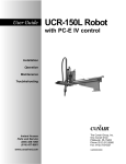
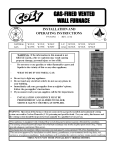
PHYSICAL FEATURES
FIGURE 1
INSTALL AND USE ONLY IN ACCORDANCE WITH THE MANUFAC·
TURER'S INSTALLATION AND OPERATING INSTRUCTIONS. DO NOT
CONNECT THIS UNIT TO A CHIMNEY FLUE SERVING ANOTHER
APPLIANCE.
Page 2
BUCK STOVE FEATURES
Before attempting to install or operate your BUCK STOVE, It is a good idea to familiarize
yourself with the features and operating controls of the stove. (Figure 1)
OPERATING CONTROLS
1. DAMPER: The damper contrails located In the center of the stove, just under t he stove top.
Ilis operated by lifting up on the control handle, and then pushing or pulling the handle. When
the handle is lowered, the control locks Into position. The damper Is fUlly open when the con·
trol is pushed if" and fully closed when the handle is pulled oul. The damper must be opened
before the doors are opened.
2. DOOR HANDLES: The door handles on the BUCK STOVE are air cooled and shielded. The
handle on the right hand door latches the doors shut, while the left hand handle is fixed. To
open the doors, rotate the right handle up, or counter clockwise one quarter turn, and pull the
doors open. The doors are closed and locked by reversing the procedure.
3. BLOWER CONTROL: The blower control switch is located on the lower right side of the
stove front. This switch controls the functioning of the builtin fan. In the "MANUAL" position,
the blower operates continuously; in the" AUTOMATIC" position, the blower is controlled by
an internal thermostat in the stove which reacts to the temperature of the air between the
stove walls. The speed of the blower is then dependent primarily on the size of the fire in the
firebox.
A
CAUTIONI DO NOT unplug the blower during stove operation!
4. DRAFT CONTROLS: The primary air draft controls are located on the lower portion of the
doors. They are operated by sliding the controls to uncover more or less of the draft air inlets.
A knob is provided which is used to operate the control and also serves a locking function. The
control is locked into position by screwing it in until it is snug.
5. UPPER WARM AIR OUTLET: Provides heat extraction from the top surface of the stove.
6. UPPER TRIM PANEL: Seals the fireplace against soot and ash, and prevents warm room
air from escaping up the chimney on masonry insert.
7. DECORATIVE BRASS KNOBS: Adds an attractive accent to the stove's appearance.
8. GOLD TRIM: Same as brass knobs for masonry inserl.
9. SIDE TRIM PANEL (2): Same as top trim panel for masonry insert.
10. AIR INLET: Allows cooler room air to be circulated through the blower and back into the
warm air chamber of the stove.
11. SIDE WARM AIR OUTLET (2): Extracts heat from the sides of the firebox.
12. STAND: Elevates free standing stove for safety and a beautiful appearance.
13. DOORS: Provides an "airtight" feature. The doors allow a much higher burning efficiency
than can be obtained with an open firebox.
14. LOWER WARM AIR VENT: Extracts heat from the bottom of the firebox. It is a primary part
of the patented air flow pattern of the BUCK STOVE.
15. HEARTH PLATE: Offers protection from spilling ashes and cinders on the fireplace hearth.
It also separates the warm air outlet from the primary draft air.
16. SMOKE HOOD OR VISOR: Helps trap any smoke which escapes when the doors are opened too rapidly. After !tle doors are opened. the natural draft of the stove will pull the smoke
back inside.
17. POWER CORD: Provides electrical power 10 operate the blower.
18. STACK: Chimney connector for free standing stove.
Page 3
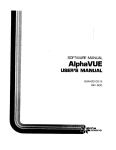
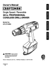
SECTION I
MASONRY INSERT INSTALLATION
26000-B
27000- B
V
II
1
J(
II
U
II
II
~ ,~=--··,--_2
---,
.--
"
II
I
I
I
I
•
II
HI
I
I
I
I
J
II,
I
BI
'11
.-
n
--~~/~.
-
I
II
I:t
~~~I
I
[
IE
I
I
..
1
61
•
•
•
1/
l~~
(~
-
~I
fI{
I
,
.~,
~-_._--'
\.;:::fuUnD
G]
rJ
t.
j
-
. Ie
.
I:::.~I
II
..
.,-'
aJm1lllJ~
;
I
II
II
IJ
_ ...
-
,J
[0 ~
II
L:f-I 11
~
~
,,1
n..
II
lIT
Jl
II
)
..
~
..
l..
.. VI
L .......
10
" '( r_~~ '7
I
, , ,'.t--\-\.' \\\\\~\-~
-
--
lu:
I II I I II
11111111'
I I
I I I , I I n
•
I
I
II
~ ~
\
I
I
R
When the Buck Stove is to be installed as an insert, the approprii:Hci kit
must be used.
FP26 for Little Buck 26000-B
FP27-B for Regular Buck 27000-8
FP28 for Big Buck 28000
Page 4
I
I
-II
..
I
J
1\
\"- \.
I
11
I
,'-
'
~-QJ
I
I
It
.f
'--"--""'-'-
---''''
I
11
...
.,~--_.-.
•-
n
/f=~~~'~='''---=~=---_. __
Il
--"----
=~,
II
1\
I
VI
~
)?
II
l
T
n
II
II
1\
''II
l{
II
11\
l.
II
h.~
-;;~?,,~"-~,••~,--
,
.,)
:it
Ii
\t
:,'c
.
a
n
l\
)r' 'I.,e:-ll
'.
. ~.; <'5:':-:\
;::::
.'.... "
11
"
Il
II
II,.
\1
" .:.:_--·".;:__;cc- ,,'
j\.
/I
.
II
'\\
It
,,'._,
-«,:-~'---
I
II
III
-
..
.,,-"
'_.'--~
. ---..
,
II
W-
I
i
II
--
----
...
••
-'.
---_.j
JI
I
•
r
.••... ,
,=;.:,___ t<::::=:'~,.,
II
II
I
I
-~.", ..
J,
_J
\1
If
'If
1\
"
,,-,.,_
I
II
II
,
'~~
n
II
,
~
IL
\1
1\
\I
'-'
'IJj:~ 1 Inl
\I
\\
11
-"-
-
'C:
.--::,~,._,~--
]1
1\
,
i
h
v
28000
I-
--
t--
A
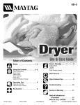
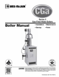
SECTION I: INSTALLATION
A
FIGURE 1
ALL DIMENSIONS SHOWN
ARE MINIMUM ALLOWED
FOR WARRANTY
INSTALLED MINIMUM CLEARANCES
Minimum Clearances:
The BUCK STOVE fireplace Models 26000-B, 27000-8 and 28000 are intended for installation
in accordance with the standard for chimneys, fireplaces, vents. and solid-fuel burning appliances,
NFPA-211 code. BUCK STOVES are NOT intended for use with a factory-built metal fireplace.
See Section III for Buck Stove/BuckMate Installation Instructions. The applicable parts of this
code are:
1. The chimney must be of masonry construction with an open cross-sectional area of at least
50 square inches (7-1/4" x 7-114" square or 8" round.)
2. The hearth must be of masonry construction and must extend a minimum of 16" in front of
the fireplace opening and a minimum of 8" to either side of the fireplace opening.
3. There must be a minimum of 8" between the side of the masonry fireplace opening and any
combustible materials, or 16" between the BUCK STOVE firebox opening and any combustible
materials. If there is not 16" from the front of the BUCK STOVE firebox opening and the front
of the masonry hearth, a floor protector must be used in front of the hearth to protect combustible materials. The floor protector is to be of non-combustible. inorganic material equal to 3/8"
thick millboard having a thermal conductivity of K=0.84 BTU/PHoF inches and must measure
38" wide. The minimum clearances for the fireplace model are shown in Figure 1.
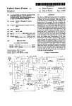
4. If your fireplace has wood trim above it, or a wood mantel. it must be located so there is at
least 20" between tile top of the BUCK STOVE and any part of the trim or mantel including
supports. This can be reduced to 18" (See Figure 2). If a modified trim kit is used (examples
shown in Figure 8, Page 9 and Bending Modification Tips for Modified Trim Kit, Page 10.)
Page 5
NOTE:
Hearth Extension must be 38" wide )(
~" thick non·combustible inorganic
material equal to ~ .. thick millboard
having a thermal conductivity of
K =0.84
BTU/P HO F
inches
Depth Dimension is determined by
Depth of Masonry Hearth.
AALL DIMENSIONS SHOWN
ARE MINIMUM ALLOWED
FOR WARRANTY
FIGURE 2
INSTALLED MINIMUM CLEARANCES TO WOOD
TRIM WITH MODIFIED TRIM KIT
REQUIRED FIREPLACE DIMENSIONS
The minimum and/or maximum fireplace dimensions for the installation of a BUCK STOVE
are:
FIREPLACE MODEL
26000-B Little Buck
27000-B Regular Buck
28000 Big Buck
HEIGHT
22114-29"
24%·31"
26%·33"
WIDTH
30-40"
34-44"
37-41"
DEPTH (MIN)
17"
17"
17"
TOOLS FOR INSTALLATION
If you decide to install your own stove, there are several hand tools you will need to do the job.
If you do not already have them, they are readily available at most hardware stores.
Hack saw
Caulking gun
Large adjustable wrench (may not be needed)
Drop cloths or newspapers
Vacuum cleaner or Whisk broom
Flashlight
1 tube of RTV silicone. Code 103 or 106, or high temperature rubber cement rated between 450°
-600°F.
7/32" drill bit and drill
Page 6
INSTALLATION PREPARATION
Fireplace
1. Locate furniture and other materials away from the front of the fireplace to allow free
access to the fireplace.
2. Cover the hearth and adjacent floor areas with the drop cloths to protect from soiling
or marring the surfaces.
3. Remove the existing fireplace damper plate.
4. Thoroughly clean the fireplace of ashes and soot.
5. Check the chimney and smoke chamber for excessive bUildups of creosote or soot.
Also, check fOf, obstructions, such as bird nest. If the chimney is excessively dirty,
clean it, or have someone clean it professionally BEFORE installing or using the
BUCK STOVE.
Stove Preparation
1. Remove the protective plastic wrapping from the stove.
2. Inspect the stove for any obvious physical damage.
3. Plug the power cord into a 115 VAC outlet to test the motor and fan. Place the blower
control in the "MANUAL" position to test.
4. Check the primary air draft controls to ensure that they slide freely and will lock
into position when the control knobs are tightened.
5. Check the operation of the damper control to ensure that it will open and close
properly.
6. Open and remove the doors and firedogs from the stove to facilitate installation.
POSITIONING THE BUCK STOVE
When positioning the stove, the following conditions MUST be metl (See Figure 3)
1. The front of the damper opening must be
positioned BEHIND the rear edge of the lintel
to ensure proper draft. (See Figure 3)
2. The vertical plane of the fireplace front must
fall BEHIND the side cold air vent on top of
the stove. (In other words. it is possible to have
the stove too far in as well as not far enough!)
3. Center the stove in the fireplace opening.
FIGURE 3
STOVE POSITIONING
Cut and Remove from
8ack Flange only.
FIGURE 4
MOUNTING THE TRIM PANELS
After the BUCK STOVE is positioned. as
shown in Figure 3, mark the mounting position of the trim panels as follows:
1. Set the top (long) trim panel in place on top
of the stove. The panel should be flat against
the outside face of the fireplace, and standing
vertically. Mark along the lower edge of the
trim panel with a pencil to make a reference
line for mounting.
2. Set the side trim panels in place, again flat
against the face of the fireplace. Mark down
the inside edge of the trim panel to make a
vertical reference line.
3. Slide the BUCK STOVE out of the fireplace
far enough to work behind the trim panel referrenee lines.
PREPARING GOLD TRIM
Page 7
4. Mount the side trim panels. (See Figure 5)
a. Position the trim panel on the reference
line.
b. Drill Mounting Holes in center of trim
panels mounting brackets to allow for
adjustment in and out If necessary.
c. Mount the trim panel using the self·tapping screw provided.
5. Ends of gold trim should be prepared for
easier insertion to touch stove top In side and
top trim panels. (See Figure 4)
6. Mount top trim panel and Insert gold trim. If
they overhang on each side trim panels, they
should be marked and cut off for neater appearance. Gold trim can also be cut in this
step.
"'Ib
FIGURE 5 MOUNTING TRlrvi PANEL
(See Figure 6)
[!$5lE. \
._-_.~
~
Ollln@
•.
ta
E 10
_I
t\lDJJllO
-
~
---
Is 01
FIGURE 6
lMARKING TOP TRIM
Page 8
7. Set the top trim panel In place and mount the same as the side panels.
8. Slide the BUCK STOVE back Into the fireplace. Check to be sure that the trim panels are pro·
perly positioned and lie flat against the front of the fireplace. If one or more of the panels is
out of position, slide the stove out and reset by loosening the mounting screws and reposi·
tloning in the slot. (See Figure 7)
FIGURE 7
CHECKING TRIM
PANEL ADJUSTMENT
MINIMUM CLEARANCE FOR BUCK STOVE
FIREPLACE INSERTS MODIFIED TRIM KIT.
FIGURE 8
INSTALLED MINIMUM CLEARANCES
Figure 8 shows a Buck Stove Fireplace Insert with a modified trim kit, installed in a masonry
fireplace showing minimum clearances for Georgian or Colonial type wood trim, on a masonry
fireplace. If wood trim is desired around the fireplace front, modify the trim kit as shown in the
bending modification tip on the following page. With modification on the stove trim kit, there
must be a minimum of 6" from the cold air intake to side wood trim, and 8 112" from stove top to
top wood trim. Wood trim should not exceed J!.I" thick.
Page 9
BENDING MODIFICATION TIPS FOR
MODIFIED TRIM KIT
FLAT DEVELOPMENT
\
\
,-- ,
;--.
I
I
I
I
.' _ .J
r --\."
- --
---
I
~
1
SIDE VIEW
TOP TRIM
FACE VIEW
TOP TRIM
I
I
<1
l
~ FACE VIEW SIDE VIEW
Page 10
SEALING THE TRIM PANELS
Standard Caulking Gun
It is necessary to seal trim panels against the
stove and against the fireplace front. This will
prevent the loss of warm room air up the
chimney.
1. (See Figure 9) Using the caulking gun and
a cartridge of RTV silicone, run a bead of
silicone all the way around the inside of the
trim panels next to the stove.
2. (See Figure 10) Attach 1 1/2" x 2" strip insulation around the back edge of the trim
panels. Set the strip back 1" from the edge.
NOTE: On rock face fireplaces, it may be
necessary to add additional pieces of
fiberglass to fill large or deep mortar joints.
FIGURE9
SEALING TRIM PANELS
FINAL STEP
1. Slide the stove back into the fireplace. Be
sure the trim panels all tit snugly against the
face of the fireplace. NOTE: Be sure the top
edge of the trim panel runs true with the
mortar joints on a brick fireplace. It it does not,
one side of the stove can be shimmed from
the bottom with metal to give a "square"
appearance.
2. Place a flashlight up through the damper
and onto the top of the stove. Visually check
all the way around the trim panels for evidence
of light seepage. Any seepage should be
blocked with the use of additional fiberglass
and RTV silicone until a tight seal is achieved. (See Figure 10)
Insulafion Strip
FIGURE 10
Page 11
ATTACHING
INSULATING STRIPS
==:J c=::J c=J
1......-.-"-"----'-"-----'"'----»----
l
-) c=:J c==J c=::J c=J
.c=J r==J r===r
FINISHED VIEW
FIGURE 11
3. Install the firedogs (or coal grate, refter to Page 56), and replace the doors.
Note: Model 28000 is standard with bottom refractory only. Rear and side refractory can
be purchased separately and must be used when burning coal.
FINAL CHECK
1. Recheck the specified clearances.
2. Remove all foreign material from the firebox area.
3. Open the primary air drafts and damper.
4. Plug the power cord into a 115 VAC outlet. DO NOT route the cord under the hearth
plate or in front of the stove to the opposite side.
5. Place a crumpled piece of newspaper in the stove. Light it and close the doors. Ensure
that the stove draws properly through the primary drafts. The paper should burn quickly
and with a pronounced roaring sound.
6. Check for smoke leaks around the doors.
7. Open the doors and install the firescreen. Check for smoke esce.ping froln the front of
the stove. Smoking usually indicates a defective or poorly positioned chimney. it a thorough
review of the installation instructions does not reveal the problem, contact your BUCK
STOVE dealer for assistance.
NOTE: The BUCK STOVE is painted with a specially formulated high temperature paint
that cures during the first two or three firings. You may notice a slight smoking effect and
an odor of burning paint when you build the first fires. This is normal and is not a cause
for alarm. In some cases, these fumes will activate a smoke alarm. Cracking a window
near the stove will allow these fumes to escape. DO NOT build a large, roaring fire until
this curing is complete or the stove finish may be damaged.
Page 12
SECTION II
FREE-STANDING INSTALLATION
26000-8
27000-8
28000
SAFETY NOTICE
If this stove is not properly Installed, a house fire may result. For your safety, follow
the Installation directions. Contact local building or fire officials about restrictions
and Installation Inspection requirements in your area.
When a BUCK STOVE is to be installed as freestanding fireplace stove, kits
No. L1 or P1 and S1 must be used.
Page 13
SECTION If
MINIMUM CLEARANCES
The BUCK STOVE Models 26000-8 and
27000-B must be installed in compliance with
the instructions contained in this manual.
A
NOTE:
Oimonsion, Shown ."Minimum CI••
III
Woll
r."""
Clearance from combustible walls and
ceilings.
Combu..i:'", Wilt
16"
flO()( ProtoctOt _
Minimum Sin Chart "A"
The minimum lateral distance between any
part of the BUCK STOVE models 26000-8
and 27000-B are shown in figures 1 and 2.
Floor Protection
If a freestanding model of the BUCK STOVE
is to be installed on a combustible floor, a noncombustible pad must be placed below it to
protect the floor from radiant heat and burning material from the stove.
FIGURE 1
WALL INSTALLATION
The pad must meet the following minimum
specifications:
• Use a Listed Floor Protector or a Floor Protector made of a non-combustible inorganic
material equal to 3/8" Thk. millboard having
a thermal conductivity of K::: 0.84 BTUlF2HoF
inches.
ANOn:
Oimll'\'ttom 5hOYWfl .q
Ft. 2H. Degrees F.
Minimum C...,..nc. to
Co~iUi'lb~ Waif.
CHART A
BUCK STOVE
MODEL
26000-8
27000-8
2S000
16"
Floor Protector
MINIMUM
SIZE:
48" x 4S" x 3/S"
53" x 4S" x 3/8"
54" x 54" x 3/8"
The BUCK STOVE must be positioned on
the pad so that there is a minimum of 16"
from the front of the door to the front of the
pad, and a minimum of 8" measured
horizontally from the sides of the stove to
the sides of the pad.
FIGURE 2
CORNER
INSTALLATION
CAUTION: There must be a minimum of 18" from any single wan pipe to a combustible
wall. If there is not 18" from single wan pipe to the combustible waH, a wall
protector must be used.
Page 14
Reduced Clearances Using Wall Protectors
(These are minimum clearances, minimal floor protection sizes and minimal wall protection
sizes, Larger sizes and clearances are allowed.)
26000-8 LITTLE
A. CORNER INSTALLATIONS
1. Using 3V2" masonry without ventilated air space.
_._----"'Floor
Protector
T
-
37"-
39"
.......'------l---l-~J-.- L_ _
Finished Floor
Line
TOP VIEW
FRONT VIEW
2, Using 3 112" masonry with 1" ventilated air space.
Wall Protector
Combustible Wall
.......
Floor
Protector
1" Air
Space
~
I
36"
!'--34W'
:
~- 50" - - .-----.,
1" Air
Space - - ' ...............\.• _ ;
TOP VIEW
Skip every other brick top
& boltom to allow for air
flow behind masonry
FRONT VIEW
Page 15
26000-8
(Continued)
3. Using 24 gao sheet metal with 1" ventilated air space.
Wall Protector
Combustible Wall
531..
1" From
Celling
31"
Floor
Protector
43"
I
t" From
Finished Floor
J,-.~.
~d=====;;;;.;:i.;;;;::"-.L_
I'"
38"
----;1
.....-----50.. - - - - ..1
FRONT VIEW
TOP VIEW
B. PARALLEL WALL INSTALLATIONS
1, Using 3 112" masonry without ventilated air space,
Combustible Wall
Wall Protector
-----.----ic::r==--;----
1
32'35112" ..
U
16"
l-e
441fz"
"i
T
39 '12"
Floor Protector
....- - - - 48" ---~~
.......- - - 5 0 . .
"\
TOP VIEW
FRONT VIEW
Page 16
26000·8
(Continued)
2. Using 3 W' masonry with 1" ventilated air space.
HI
32
ITU
1" Air
Space ~_.-'
1" Air
Space
_ 32"
1-4--35"---
~
.:j
38'12 !.L.....-_ _
1 - + - - - 44 1/B"'----JIoj
~::::J:::.-Crl=J::=:c.~
~1'/
~ry
Skip
other brick top
and bottom to allow for air
flow behind masonry
Floor
Protector
FRONT VIEW
TOP VIEW
3. Using 24 gao sheet metal with 1" ventilated air space.
Combustible Wall
Wall Protector
42"_
1" Air
Space
)01
Floor Protector
1" Air Space
Maintairl 1" space between
top and bollom for air flow
behind protector
L-A..._---441/B':....,'----~
FRONT VIEW
TOP VIEW
Page 17
27000·B BUCK STOVE
A. CORNER INSTALLATIONS
1. Using 3 1/2" masonry without ventilated air space.
Wall Protector
Combustible Wall
1'----'1--'--' _ _'LLJ'
10lh"
'f
7"
-'f'"
"
Floor
Protector
l
4'"
Finished Floor
line
TOP VIEW
FRONT VIEW
2. Using 3V2" masonry with 1" ventilated air space.
Wall Protector
Combustible Wall
"
Floor
Protector
T
," Air
Space
45"
1" Air Space ,,-''''
TOP VIEW
Skip every other brick top
& bottom to allow lor air
flow behind masonry
FRONT VIEW
Page 18
27000~B (Continued)
3. Using 24 gao sheet metal with 1" ventilated air space.
Combu tibia Wall
Wall Protector
1" From
Ceiling
31'1...
~
31"
Floor
Protector
5314'
I
'_+--
41"
45"
\1"
From
Fi,lished Floor
1" Air Space
1--- 41"
~---
-1
----
~===i:::::::i...-
53"-----1
FRONT VIEW
TOP VIEW
B. PARALLEL WALL INSTALLATIONS
1. Using 31/2" masonry without ventilated air space.
Combustible Wall
Wall Protector
1
u··..
3 5"38"-"
471/2'
'1
I o o t - - - - 51" - - - , . f
53"
T
41"
Floor
Protector
I....
"I
TOP VIEW
FRONT VIEW
Page 19
27000-B
(Continued)
2. Using 3 112" masonry with 1" ventilated air space.
Combustible Wall
Wall Protector
3'/2"
TO<
45"
1" Air
Space
Ie
40V2'-'--to-i
I...
....r . - - - - 44 "-------to{
1-'4------ 49 5/8'-'------i~.._tl
Floor
Protector
1
- -- 1" Air
Space
Skip every othor brick tall
and bOnOHl 10 iiii'JW for ar,c
flow behind masonry
FRONT VIEW
TOP VIEW
3. Using 24 gao sheet metal with 1" ventilated air space.
Combustible Wall
Wall Protector
--\----------------------f-------.:..
rr
11
36" 42V4"
16"
1" Air
Space
r--
44"
,.\
Floor
Protector
45"
'--"'.-,- 44"
----------Maintain 1" space between
top and bottom to allow tor
air flow behind protectof
IN\Ioc------49 5/8'~------{
FHONTVIEW
TOP VIEW
Page 20
MASONRY CLEARANCE REDUCTION
COMBUSTIBLE WALL
../'!(
1" Minimum air space between masonry
and combustible wall.
4" nominal
~:jJ_---"''"4rll:;::;--- Corrugated metal wall ties
brick wall ::':---R:ll'I::'~~
Skip every other brick bottom and __~~~~~~
top for ventilation
A strip of heavy gage steel may be
used for support------------~·
~
1
(REF.• NFPA 211 CODE)
Screw anchor (or nail)
....
~"-
MASONRY WALL TIE
Clearance Reduc1lon
1" Non-<:ombusllble spacer such as stacked washers,
small diameter pipe, tubing, or electrical conduit.
Masonry walls may be attached to combustible walls using wall ties.
DO NOT place masonry wall ties directly behind appliance or connection.
(REF.• NFPA 211 CODE)
Page 21
MINIMUM CLEARANCES
The BUCK STOVE Model 28000
The BUCK STOVE Model 28000 (NOT UL
LISTED) must be installed in compliance with
lhe instructions contained in this manual.
... NOTE:
OH1,*o~n, Shown
Wall
.re
Mfllimum CI.,,·",nc::1' to
Comb.... ,,:>..
The minimum lateral distance between any
part of the 28000 and a combustible wall is 36".
(See Figures 3 & 4)
w.1l
)6"
floot P,ot«Cla, ...
M,n""... m S,lt Ch~1 "A'"
Floor Protection
If a freestanding model of the BUCK STOVE is
to be installed on a combustible floor, a noncombustible pad must be placed below it to
protect the floor from the radiant heat and
burning material from the stove.
t6"
Use a listed Floor Protector or a Floor Protec·
tor made of a non-combustible inorganic
material equal to 3/8" Thk. millboard having a
thermal conductivity of K:::: 0.84 BTU in.
(See Page 14)
Ft.aH. Degrees F.
FIGURE 3
WALL INSTALLATION
With Wall Protector
Refer to NFPA-211-1980, (b), except that the
MINIMUM DISTANCE TO A PROTECTED WALL
SHALL BE 18".
£
HOff:
OH1\1n~ll1o Shown
,'.
MIOtMl,.jm C~..,~. 10
Cot'tOu'hb'-: W.U
3<)'
"UNLISTED PRODUCTS MUST BE INSTALLED
WITH THE ACCEPTANCE OF THE AUTHORITY
HAVING JURISDICTION AND IN ACCOR·
DANCE WITH THE MANUFACTURER'S INSTRUCTIONS",
The BUCK STOVE must be positioned on the
pad so there is a minimum of 16" from the front
of the stove to the front of the pad and a
minimum of 8" from the side of the firebox
opening and the side of the pad.
FIOOt P,ott<JOf ""
MtnuTtVm SIU Chll1 "A"
FIGURE 4 CORNER INSTALLATI'ON
Page 22
CHIMNEY
The BUCK STOVE Models 26000-B and 27000-B are designed for connection to either an 8"
inside diameter Underwriters' laboratories, Inc. listed all-fuel residential type and Building Heating
Appliance Chimney, or to a masonry chimney which meets the specifications of the National
Fire Protection Association's 211 Code and has a minimum cross section area of 50 square
inches (7 1/4" x 7 1/4" or 8" round).
CAUTION: Use only U.l. Listed type HT chimney rated at 2100° F for freestanding installations.
TOOLS FOR INSTALLATION
1/2" • 9/16" combination wrench
7/32" drill bit and drill
3/8" magnetic socket chuck adapter, 3/8" wrench (box or socket) or adjustable wrench.
PREPARING THE STOVE FOR INSTALLATION
1. Remove the protective plastic wrapping from the stove.
2. Inspect the stove for any obvious physical damage.
3. Plug the power cord into a 115 VAC outlet to test the motor and fan. Place the blower
control in the "MANUAL" position to test.
4. Check the primary air draft controls to ensure that they slide freely and will lock into
position when the control knobs are tightened.
5. Check the operation of the damper control to ensure that it will open and close properly.
-
STAND KIT L-1
STOVE MODEL
26000-B Little
27000-B Regular
"A" Dimension
Flush to Front
1 1/4"
28000 Big
PEDESTAL KIT P-1
STOVE MODEL
26000-B Little
270oo-B Regular
28000 Big
"A" Dimension
1 1/4"
2 1/2"
FIGURE 5
STAND MOUNTING
6. Open and remove the doors, firedo~s, side liners and the cast refractory material from
the bottom of the stove to facilitate Installation.
7. Attach the legstand by tilting the stove on its back, center the legstand on the bottom
of the stove and position back 7/32" from the dimension shown in chart left of Figure 5.
When positioned, drill holes through holes of mounting stand and attach using 1/4" Dia.
self-tapping screws provided. (See Figure 5.)
Page 23
8. Attach the stack by placing the stack
brackets down on the lip on the Inside
lower edge of the stack. Insert the bolts
through the holes In the damper
brackets and fasten securely with the
lock washers and nuts provided. Be sure
the stack sits squarely on the top of the
stove with the gasket material making a
good seal. (See Figure 6.)
:.----Slack Clamp
PREPARING THE BUCK STOVE
LOCATION
-~~ lo<kwo$h.r
1. Select an installation location that will give
the best airflow from the front of the stove to
the remainder of the home.
~
2. Place the protective floor pad In position.
3. Place the stove on the pad making sure the
minimum clearance specifications are met.
(See Figures 1 through 4)
FIGURE 6
MOUNTING STACK
4. Install the cast refractory bottoms and the
side liners.
5. Install the firedogs (or coal grate) and
replace the doors.
6. In connecting to an existing masonry flue,
first ensure that the flue conforms to the
NFPA·211 Code. (Refer to Page 5) andlor
consult your local code for proper procedure.
I
. -'-, -
I
CEILING
t
SEE CHIMNEY MANUFACTURER'S
INSTALLATtON INSTRUCTION' FOR
INSTALUNG CHIMNEY AND CEll·
ING TRIM PLATE,
DETERMINING THE CHIMNEY
LOCATION
i
I
I
1. Ceiling penetration
r - ~Minjmv~
.M'I-board
or Equivol4lflt.
, Suspend a plumb bob from the ceiling above
the stove so that the weight is hanging in the
center of the stack. (A small weight on a string
will serve as a plumb bob.) Mark the ceiling
where the string is suspended to locate the
center of the chimney hole. (See Figure 7)
After locating the center of the hole, install the
chimney as per the chimney manufacturer's in·
structlon, using Underwriters' laboratories,
Inc. listed all-fuel residential type or Building
Heating Appliance Chimney.
·See Section If, Floor Protection, Page 14.
FIGURE 7
CHIMNEY MOUNTING
CEILING
Page 24
Through-the-wall Penetration
- ATTIC-
Mark the plumb line on the wall directly behind
the center of the stack (See Figure 8). Place
the vertical position of the stove pipe and the
elbow in position and project a point onto the
plumb line level with the center of the elbow.
Measure up so there will be at least 1/4" rise
per foot of horizontal conneclor plpo, maintain
c1earnaces to colling noted In Figure 8. This will
give you the cenler of the hole for the chimney
penetration.
CElllNG 18"MIN.
rRIM P l A r E /
After locating the center of the penetration, in·
stall the chimney as per the chimney manufacturer's specifications.
Connect the stack to the chimney using #24 gaminimum, blued or black steel connector pipe,
8" diameter, for models 26000-8,27000-8 and
28000. DO NOT use galvanized pipe. Connect
each section so the crimpled end faces
downward, and secure each section to each
other using at least three steel sheet metal
screws or rivets.
-I
_..
ReIer to Figures
1 & 3 lor appllc·
able model
~.
,
clearance·
...l
FIGURE8
WALL CHIMNEY
MOUNTING
When the chimney conneCtor is connected using a 900 elbow and penetrating a wall into a flue,
the minimun clearance from the top of the chimney connector and a ceiling is 18 inches (See
Figure 8). In addition, all combustible materials must be removed around the complete circumference of the thimble extending through to the masonry of the flue. Refer to local building
codes or NFPA-211 Code for proper installation or use a UL listed wall thimble.
Connections to an existing masonry flue must conform to the 1976 edition of the Uniform
Mechanical Code, Section 915, paragraph E (Entering Masonry Chimney), which states:
"A connector entering a masonry chimney shall extend through the wall to the inner face of the
liner, but not beyond, and shall be firmly cemented to masonry. A thimble may be used to
facilitate removal of the connector for cleaning, in which case the thimble shall be permanently cemented in place with high temperature cement. The chimney connector shall enter the
chimney not less than six inches from the bottom of the chimney. The chimney shall be
provided with a cleanout. If six inches are not available, a cleanout shall be provided".
•See Section II, Floor Protection, Page 14
FINAL CHECK
1. Recheck the specified clearances.
2. Remove all foreign material from the firebox area.
3. Open the primary air drafts and damper.
4. Plug the power cord into a 115 VAC outlet, do not route the cord under the slove.
5. Place a crumpled piece of newspaper in the stove. Light it and close the doors. Ensure
that the stove draws properly through the primary drafts. The paper should burn quickly
and with a pronounced roaring sound.
Page 25
6. Check for smoke leaks around the doors.
7. Open the doors and install the firescreen. Check for smoke escaping from the front of the
stove. Smoking usually indicates a defective or poorly positioned chimney. If a thorough
review of the installation instructions does not reveal the problem, contact your BUCK
STOVE dealer for assistance.
TIPS ON FIRE BURNING
ASH BED - Prolongs burn and helps the thermostat function properly.
For best result, the ash bed should be equal to the top ash bar.
GREEN WOOD vs. SEASONED WOOD - Green wood has a high
moisture content, and therefore requires a hotter ignition temperature.
Seasoned wood - cut at least one year before use - allows for a quicker,
prolonged burn and more complete combustion.
SPLIT WOOD vs. ROUND WOOD - Split wood burns easier and more
rapidly, whether it's seasoned or green. If used after starting a fire,. it should
be packed tightly to achieve a longer burn. Round wood burns longer, but
requires more effort to start. Inserting a round piece over a bed of red coals
with the damper and drafts open will help it catch fire. Round wood should
be used to accomplish an all-night burn.
FIRE STARTERS - Be highly selective In choosing a quick fire starter
for use In your BUCK STOVE. NEVER START A STOVE FIRE WITH
GASOLINE, CHARCOAL LIGHTING FLUIDS,. OR OTHER CHEMICALS
WHICH COULD EXPLODE. For best results, use Buck Lite™,. a safe,
quick fire starter available from your Buck Stove dealer. Regular, noncolor newsprint may also be used.
Page 26
HANDLE SHIELD MOUNTING
The shields are required for proper installation
of your Buck Stove. They are to be mounted
parallel with the handle, and spaced 21f2" from
the front of the boss to the front edge of the
clamp. (see illustration).
HANDLE SHIELD MOUNTING
CATALYTIC CONVERTER RETRO-FIT
UL LISTED FOR USE WITH MODELS
26000, 26000-8, 27000, and 27000-8
Your BUCK STOVE has been designed to be one of the safest, most efficient and economical
woodstoves in the world. Now, these qualities can be further enhanced with the addition of
the ARDEN INDUSTRIES "SMOKE GENIE" CATALYTIC SYSTEM, available at your BUCK
STOVE dealer.
MODEL C200/R 100 for LITTLE BUCK models
26000 and 26000-B
MODEL C200/R200 for REGULAR BUCK
models 27000 and 27000-B
MODEL C300/R300 for BIG BUCK
MODEL 28000 (Not UL Listed)
CUTAWAY SHOWING CONVERTER
LOCATION IN UPPER REAR SECTION
OF STOVE.
Page 27
SECTION III
BUCKMATE FIREPLACE INSTALLATION
ZC-2-01/26000-B
ZC-3-01/27000-B
ZC-3-01/FP-201
I
I
I
f .
I
@New Buck Corporation 1985
Page 28
A
CAUTION - Refer to chimney manufacturers instructions for assembly and
disassembly of chimney parts. 8e sure
to follow chimney instructions for proper clearances to combustibles and proper air spacing required.
•..•. __•. Chimney Cap
Roof Flashing
Fire Slop Radiation Shield
- - - Zero Clearance Cabinet·Model ZC·2·01. ZC·3·01
Slack/Damper Assembly·Provided with Buckmate
Buck Slove Fireplace· Model 26000-B. 270oo-B.
or FP·201 Fireplace
Hot Air Grills
Cold Air Return
On Stove
--+-tf
A required
CAUTION: Vented Roof Flashings are
with certain chimney installa-
- - Fireplace Trim PanetsProvided with ZC·2·01. ZC·3·01
tions. 8e sure to use exact roof flashing
as indicated on page 30 and 31.
Page 29
PARTS REQUIREMENTS
LISTED BUCK STOVE PARTS
ZC-2-01
26000-B
ZC-3-01
BUCKMATE Zero Clearance Cabinet Assembly for 26000-B Stove
Little Buck Stove
BUCKMATE Zero Clearance Cabinet Assembly for 27000-8 Stove
and FP-201 Fireplace
Regular Buck Stove
Fireplace
Flashing (Use on OCR installations using Simpson-Dura-Vent pipe)
Flat Roof Flashing (use on OCR installations using Simpson Dura-Vent pipe)
27000-B
FP-201
ZC-182
ZC-183
LISTED DURA-VENT CHIMNEY PARTS
DCR-P
OCR-FRS
DCR-SC
DCR-C
8" Triple Wall Pipe Sections: 9", 12",24", 36".
8" Firestop Radiation Shield
8" Storm Collar
8" Chimney Cap
OPTIONAL DURA-VENT CHIMNEY PARTS
DCR·IS
OCR-WS
OCR-RSA
OCR·E
OCR·ES
8" Insulation Shield
Wall Strap
Extended Roof Bracket
150 or 300 Elbows (2 Maximum)
Elbow Strap
OPTIONAL 21000 DURA-PLUS DURA-VENT CHIMNEY PARTS
SOp·p
SOP-SS
SOP-FRS
SDP-SC
SOP-C
SOp·F
8" Triple Wall insulated pipe
sections 9", 12", 24", 36'
8" Starter section
8" Firestop Radiation Shield
8" Storm Collar
8" Chimney Cap
8" Flat Roof Flashing
SOP-TF
SOP-IS
SDP-WS
SOp.ES
SOp·E
SOp·ES
8"
8"
8"
8"
8"
8"
Roof Flashing
Insulation Shield
Wall Strap
Extended Roof Bracket
15° or 30° Elbows (2 max.)
Elbow Strap
OPTIONAL 2100° STANDEX SUPERFLUE MODEL "S" CHIMNEY
2P8
FST8
RRJS8
SC6810
AS8
2PSS8
AA8
SFRC8
SFSC8
RF8
2E8
8"
8"
8"
8"
8"
8"
8"
8"
8"
8"
8"
Double Wall Pipe Sections: 12", 18",24",36",48",60"
Firestop Thimble
Roof Joist Shields
Storm Collar
Attic Insulation Shield
Chimney Support System
Chimney Support Strap
Chimney Cap
Chimney Cap
Flashings: 1/12 to 6112, 7/12 to 12/12, 12/12 ro 21/12, flat
Elbows: 150 or 30° (2 maximum)
Note: Exterior casing may be stainless or galvanized.
Page 30
OPTIONAL 17000 METAL-FAB "A l t CHIMNEY
A8
AFSA8
ASC8
AWB8
ASB
ACB8
AF8
AA8
A1S8
8"
8"
8"
8"
8"
8"
8"
8"
8"
Triple Wall Pipe: 12", 18",24",36"
Firestop Assembly
Storm Collar
Wall Band
Support Band
Chimney Cap
Flashings: Adjustable, flat tall, 6/12 to 15/12, 16/12 to 24/12
Elbows: 150 or 300 (2 maximum)
Insulation Shield
OPTIONAL 2100° METAL-FAB TEMP/GUARD CHIMNEY
8TG
8TGFSA
8TGRSH
8TGIS
8TGSB
8TGWB
8TGA
8TGF
8TGC
8TGSC
B"
8"
8"
8"
8"
8"
8"
8"
8"
8"
Insulated Pipe: 6", 12", 18",24",36"
Flrestop
Radiation Shield
Insulation Shield
Support Band
Wall Band
Elbows: 150 or 300 (2 maximum)
Flashings: 0/12 to 5/12,6/12 to 15/12, 16/12 to 24/12, tall flat
Chimney Cap
Storm Collar
OPTIONAL 2100 0 SECURITY MODEL ASHT
8L
BE
8ST
8S0
8BS
8BM
SF
8RSA
8C
8" Insulated Pipe: 8", 12", 18",24",36"
8" Elbows: 15° or 300 (2 maximum)
8" Roof Support
8" Offset Support
8" Roof Brace
8" Wall Band
8" Flashings: Flat (F), Peak (FP), Adjustable (FA, FB, FBB)"
8-" Allie Radiation Shield
S" Chimney Cap: Mushroom (CG), Rain (CPR), Spark Arrestor (CPE)
* NOTE - Storm Collar and Roof Radiation Shields are included. with Flashing.
CAUTION: Do not mix Chimey Parts as a fire may result. Use one model of chimey parts completely for a UL Listed installation.
CAUTION: Read through all of these instructions carefully. Follow Chimney Manufacturer's In·
stallation exactly. Failure to install the Cabinet, Stove, and Chimney as described in the instructions will void the manufacturer's warranty and may have an affect on your Homeowner's insurance and UL Listing Status. A major cause of chimney related fires is failure to maintain
required clearances (air spaces) to combustible materials. It is of utmost importance that these
parts be installed only in accordance with these instructions.
SPECIAL FEATURE: The FP-201 Fireplace may be removed and the Model 27000-B Stove may
be installed in its place in the ZC·3·01 Cabinet. This is a UL Listed procedure and does not
affect the listing, safety, or warranty on the recognized components.
Page 31
--he Zero-Clearance BUCKMATE Fireplace Cabinet Model ZC-2-01 (hereafter referred to as the
UUCKMATE) is designed to facilitate the installation of a BUCK STOVE Model 26000-B (hereafter
referred to as the BUCK STOVE Fireplace (FP) ) in a family dwelling, where minimum clearance
is desired. The Zero Clearance BUCKMATE Fireplace Cabinet Model ZC-3-01 is designed to
facilitate the installation of a BUCK STOVE Model 27000-B or the FP-201 Fireplace. Just as
the name implies, the Zero Clearance BUCKMATE may be installed in direct contact with building
(onstruction. Installed properly, the unit then provides a safe, insulated housing for the BUCK
STOVE Fireplace.
tlormally, the installation will be accomplished in two stages: 1) Installation of the BUCKMATE
f:ireplace Cabinet and associated framing and morlarwork, and 2) later installation of the BUCK
~3TOVE (FP) into the BUCKMATE Fireplace Cabinet. Note· The ZC-3-01 and FP-2.01 are in~. tailed at the factory as one unit.
I NSTALLATION PRECAUTIONS
The following precautions are mandatory for a safe installation:
1\. Compliance with local building codes and regulations is mandatory.
U. Be careful not to damage unit in handling and unpacking component parts and accessories.
C. The only factory approved chimney pipes to be used are Underwriters Laboratories listed
Simpson Dura-Vent Chimney ModeI8-DCR and 8SDP, Standex Model "S", Metal-Fab Model
"A" and "TG", and Secunty Model "ASHT" vented to the outside of the building.
D. The chimney must extend a minimum of three feet above the highest point where it
penetrates the roof (three feet above a flat roof or up to a 2/12 pitch roof), and the chimney
must extend a minimum of two feet higher than any portion of the bUilding within ten feet
of the chimney. The minimum height is 14112 feet. The maximum height is 42 feet. A two-inch
clearance must be maintained between the chimney and any combustible materials at
all points.
fe:. A rain cap must be used to terminate the chimney to prevent down-draft. Use the factory
approved rain cap which is approved for the type chimney being installed.
F. Use only New Buck Corp. Roof Flashings when installing the BUCKMATE Cabinet, Chimney
and applicable Fireplace with the 1700° Simpson Dura-Vent OCR Chimney.
n. The BUCKMATE Fireplace Cabinet is not intended for use in mobile homes.
H. DO NOT build a fire directly inside the BUCKMATE. It is designed solely for housing the
BUCK STOVE Fireplace.
SELECTING A CHIMNEY INSTALLATION AND LOCATION
1 here are tw<? basic types of chimney installations possible with the BUCKMATE; Straight up
lilrough a celJng, and chase installalion, either outside or inside. These are normally used as
hllows:
.A. CAUTION • Re fer t0 c h'Imney manu facturers
instructions for assembly and disassembly
of chimney parts. Be sure to follow chimney
instructions for proper clearnaces to combustibles
and proper air spacing required.
Chimney Gop
Chln1l1&Y Cnp
~'''~
",.~~.-. _
-
"~
Storm Collar
\
._ Fioshoog
_______._ _ ':0, ::-:--- Ch,mn<y p,pe
--
=
·f~- Melal FIleslop
Simon CoHa,
-
Flashmg
~N-·-·-MelatFireSIOP
-
FIGURE 1
l C Cab,nel
Z C Cablnel
FIGURE 2
Through Ceiling &
Normal Pitch Roof
Page 32
Through High
Pilch Roof
a. Straight up through ceiling: (See Figures 1 and 2). This is a simple installation normally used
when installing a BUCKMATE inside an existing room, and in some cases, in new construction. Refer to Figure 3 if an offset to clear an obstruction is needed.
A
CAUTION· Refer to chimney manufacturers
Instructions for assembly and disassembly
of chimney parts. Be sure to follow chimney
Instructions for proper clearances to com·
bustlbles and proper air spacing required.
'\;:fi.!:r
Chimney Cap
, Chimney Cap
1-+-_ _'__ Chimney Pipe
f=lT---
Storm
- Flashing
Collar
Chase
-_.- Flashing
Chimney Pipe
.. Elbows
+-:?"~"c--:-"::' Adjustable Chimney
le. Cabinet
_ ..._ - - Z.C.
Cabinet
FIGURE4
FIGURE3
EXTERIOR WALL CH/\SE
OFFSET TO CLEAR
OBSTRUCTION
b. Chase Installation: (See Figure 4). A chase is an enclosure built specifically to house a
chimney. The interior of a chase is open from the BUCKMATE to the rool, eliminating the
need to cut through ceilings and the roof. Normally, a chase is built outside and against H'e
exterior wall 01 a home. A hole is cut through the wall, and the BUCKMATE is located in He
bottom of the chase, with the front of the unit flush with the interior wall. Chases are
commonly veneered on the outside with brick, stone or wood to give the appearance of a
conventional fireplace flue. Occasionally, they are built inside and boxed in, similar to a
stairwell. When making a chase installation, it Is important to read the chimney manufa::>
turer's instructions prior to building, as there are specific requirements for bracing a Ire'}standing flue that must be planned for. There are also occasions where olfsets are used
within a chase to accommodate unusual building designs, or to locate the BUCKMATE
further into a room.
NOTE: Chases require waterproof covers that are not commercially available due to the
nonstandard designs of chases. Make sure that units fabricated by local sheet metal
shops completely overhang the chase and all masonry. Otherwise, rain leakage or freczIng and fracturing of standing water will occur.
Page 33
FRAMING CONSTRUCTION AND INSTALLATION
ZC-2-01/26000-B (Little BUCKMATE Cabinet and Regular Buck Stove Fireplace)
FRAMING CONSTRUCTION
Except as noted, the BUCKMATE can be installed almost anywhere you desire. There are,
however, a few clearance and framing restrictions that must be followed. See figure 1 and 2
to make sure that these clearance restrictions are met. It is much wiser to place your BUCKMATE
cxrectly at the start of the installation than to be forced to relocate it after much of the work is done.
You must ensure that the floor is of adequate strength to accept the load of this unit. If inadequate, the floor will require additional support, such as bracing. NOTE: A wooden base constructed of plywood or 2" x 4" boards is required in order to get proper clearance above the
extended hearth (millboard, rock, stone, etc.)
Good planning is essential for a satisfactory installation, therefore, at this point you should have
decided where the BUCKMATE is to be located and the route the chimney will follow to the
roof - straight up, or chase. If you cannot decide the best route, contact your BUCK STOVE
Dealer for assistance with the planning.
CHIMNEY INSTALLATIONS
Position BUCKMATE for chimney installation as follows:
a, Thoroughly clean the area where the unit will be placed.
b, Layout the location on the floor and construct base (see Figure 1).
c If chimney is to be installed through a ceiling, drop a plumbline, locate, and mark point on
ceiling directly over center of BUCKMATE chimney adapter.
d, Install the chimney in accordance with chimney manufacturer's recommendations.
CAUTION: Follow the instructions for the type chimney you're building, i.e., straight-up or chase.
e Note, the maximum height of chimney is 42 feel.
Finished Wall
WARNINGAllnstall the hearth
protector only as specified. The
hearth extension must extend a
minimum of 16" in front of the
fireplace opening and must be 38"
wide minimum.
(Total area to be covered Is 19 3; ' ' '
by 38",)
o
.....
.~~~
I Finished Hearth
-*-----1
A
Floorline
Wooden Base
FIGURE 1
base for BUCKMATE must be level with or slightly higher than finished hearth height- dimens,on (A) Figure 1, Front of BUCKMATE cabinet must be recessed 2 112" from finished wall.
Page 34
ZC·2·01/26000·8
Framing must be accomplished after the BUCKMATE Is set In place. The chimney can be in·
stalled after framing, but Installation Is considerably more difficult and, in some cases, im·
possible. Therefore, It Is recommended that the chimney be Installed prior to framing when a
choice exists.
Adjacent Room of
Exterior Chase
Interior
Location
FIGURE 2
Above (Figure 2) are Framing location examples, with depth dimensions for some typical con·
figurations. These are finished measurements so install accordingly.
1. Before framing, combustible floor coverings (carpet, tiles, etc.) must be removed to outer
dimension of unit framing, including the 16" x 38" area for the hearth extension.
FIGURE 1·A: Safety shield for millboard hearth
extension.
Attach safety
shield using
~ sheet metal
~
screws
FIGURE 1·B: Safety shields for brick or rock hearth
(Note: Cut vertical shield to Fit Installation
height as needed. Use 26 Ga. Minimum
metal being sure to cover any
combustibles on the base.)
WARNING:Alnstall
the
hearth protector only as
specified. The hearth exten·
sian must extend a minimum
of 16" in front of the fireplace
opening and must be 38" wide
minimum.
o
r -_ _ ~....,Attach
safety
shield using
sheet metal
scews
.'
. '.
I( I<
16"----Jl
19J/4"~
2. Set BUCKMATE unit In place and attach safety shield to unit as shown In Figure 1·A anD
1·B. You must place a non·combustlble materlaI3/S" thick millboard or equivalent .084K factor
or 2" of masonry (brick or rock) over this area as a minimum.
3. Frame the BUCKMATE using 2" x 4" studs or local building code framing. Some minor fram
Ing restrictions are required:
a. Adjacent side walls must be at least 29% from door opening of the BUCK STOVE 26000-8
b. The overall opening dimensions must be at least 38" wide and 34 Jh" high.
c. Framing must protrude 2112" to allow for finished wall to come flush with the back of the'
BUCKMATE trim panel. (See Figures 1A and 1B.)
Page 35
ZC-2-01 /26000- B
A
CAUTION: Refer to chimney manufacturers Instructions for assembly and
disassembly of chimney parts. Be sure
to foHow chimney instructions for proper clearances to combustibles and proper air spacing required.
Chimney Pipe
Y~'7"""S""'H'--
2" • 4" Slu<l<ling
Double Iieado,
A Double Headm mus' be used on 3
toad br.,:uing wall This- musl be done.
12" above cabinet.
Sl"lllo H•• de,
A Siogle l'imujm must bo used as nart
of front haming, v~rHca. 2" x 4'''50
must be turned flat
NOTE; Finjshed wall must be
2'b .,. in honl of face of le.
CatJ{flet (wi! hout hood panel).
WARNING
Ins'aH tho hea'th
pfot0Ctor only 39 sJ)l!ldHed Th-it
hfUU1tt ftxtoflslon mUll' ftxtond a
ffitnimom of 16" In front 0' ttl",
fiutptacft opitolng lind mwn be 38"
wtde m~olmum.
FIGURE3
EXTERIOR ROOF OR CHASE
Page 36
WARNINGAInstall the hearth
protector only as specified.
The hearth extension must extend a minimum of 16" in front
of the fireplace opening and
must be 38" wide minimum.
ZC·2·01/26000·B
A CAUTION:
Refer to chimney maufac
turers instructions for assembly anj
disassembly of chimney parts. Be sure
to follow chimney instructions for proper clearances to combustibles and proper air spacing required.
o
Chlmnev Cap
-
Stolm Collal
Hoof
Ftas'uo~
Chimney Pipe
~~~?1~rr:- Use File Code Sheel Rock
NOTE:
A Double Header mus, be used on a
load hearu1Y wall as. Illustrated In
Figure 3
2" )( 4·' SlucJdmg
~--
A Smgle Header must be Installed
abolle caoHlet
VertIcal 2"
J:
4'''5 must be turned f1al
Note:
.-_._-- Finished wall must be 2 1/ , " If\ front of
lace of ze, Cabmet ~Wllhoul hood
It 1m a Itactled)
FIGURE 3A CORNER LOCATION FRAMING
WARNINGAlnstal1
the
hearth protector only as
specified. The hearth exten
sion must extend a
minimum of 16" in front of
the fireplace opening and
must be 38" wide minimum.
o
Page 37
FRAMING CONSTRUCTION AND INSTALLATION
ZC-3·01/27000-B (Regular BUCKMATE Cabinet and Regular Buck Stove Fireplace)
ZC·3-01/Fp-201 (Regular BUCKMATE Cabinet and BUCK STOVE Fireplace)
FRAMING CONSTRUCTION
Except as noted, the BUCKMATE can be installed almost anywhere you desire. There are,
however, a few clearance and framing restrictions that must be followed. See figure 1 and 2
to make sure that these clearance restrictions are met. It is much wiser to place your BUCKMATE
correctly at the start of the installation than to be forced to relocate it after much of the work is done.
You must ensure that the floor is of adequate strength to accept the load of this unit. If inade·
quate, the floor will require additional support, such as bracing. NOTE: A wooden base constructed of plywood or 2" x 4" boards is required in order to get proper clearance above the
extended hearth (millboard, rock, stone, etc.)
Good planning is essential for a satisfactory installation, therefore, at this point you should have
decided where the BUCKMATE is to be located and the route the chimney will follow to the
roof· straight up, or chase. If you cannot decide the best route, contact your BUCK STOVE
Dealer for assistance with the planning.
CHIMNEY INSTALLATIONS
Position BUCKMATE for chimney installation as follows:
a. Thoroughly clean the area where the unit will be placed.
b. Layout the location on the floor and construct base (see Figure 1).
c. If chimney is to be installed through a ceiling, drop a plumbline, locate, and mark point on
ceiling directly over center of BUCKMATE chimney adapter.
d. Install the chimney in accordance with chimney manufacturer's recommendations.
CAUTION: Follow the instructions for the type chimney you're building, I.e., straight-up or chase.
e. Note, the maximum height of chimney is 42 feet.
Finished Wall
WARNINGAlnstall the hearth
protector only as specined. The
hearth extension must extend a
minimum of 16" in front of the
fireplace opening and must be
42%" wide minimum.
(Total area to be covered is 19Y~"
by 42'12".)
o
Finished Hearth
'.
~
Wooden Base
FIGURE 1
A
Floorline
~k.-I
~4E---- 16" ---~
~-----193j"'---
Base for BUCK MATE must be level with or slightly higher than finished hearth height . dimen·
sian (A) Figure 1. Front of BUCKMATE cabinet must be recessed 2%" from finished wall.
Page 38
FRAMING
ZC-3-01/27000-B and ZC·3-01/FP-201
Framing must be accomplished after the BUCKMATE is set in place. The chimney can be in·
stalled after framing, but installation is considerably more difficult and, in some cases, im·
possible. Therefore, it is recommended that the chimney be installed prior to framing when a
choice exists.
26'12"
Adjacent Room of
Exterior Chase
_L
Interior
Location
Above (Figure 2) are framing location examples with depth dimensions for some typical can·
figurations. These are finished measurements so install accordingly.
1. Before framing, combustible floor coverings (carpet, liles, etc.) must be removed to outer
dimension of unit framing, including the 16" x 421/2" area for the hearth extension.
FIGURE 1·A: Safety shield for millboard hearth
extension.
k----
Attach safety
shield using
...... sheet metal
screws
FIGURE l·B: Safety shields for brick or rock hearth
(Note: Cut vertical shield to Pit Installation
height as needed. Use 26 Ga. Minimum
metal being sure to cover any
combustibles on the base.)
WARNINGAlnstall the
hearth protector only as
specified, The hearth exten·
sion must ext end a
minimum of 16" in front of
the fireplace opening and
must
be 42 V~" wide
minimum.
o
Attach safety
shield using
sheet metal
scews
.',
1<'----- 16" ----)I
~---193/", ---}j
2, Set BUCKMATE unit in place and attach safety shield to unit as shown in Figure 1·A and
1·B. You m~st place a non-combustible material j~" thick millboard or equivalent K Factor =
,Oa4/BTU/F HO F inches minimum. Note: 3/a" thick millboard may be used when installing the
ZC-3-01 and 27000-B.
3. Frame the BUCKMATE using 2" x 4" studs or local building code framing. Some minor framing restrictions are required:
a, Adjacent side walls must be at least 16" from the outer edge of the BUCKMATE
trim panel.
b. The overall opening dimensions must be at least 421/2" wide and 36314" high.
c, Framing must protrude 21/2" to allow for finished wall to come flush with the back of the
BUCKMATE trim panel (See Figure 1A and 1B),
Page 39
ZC-3-01/27000-B and ZC-3·01/FP.201
A
=-=-:::.'.........-
CAUTION: Refer to chimney manufacturers Instructions for assembly and
disassembly of chimney parts_ Be sure
to follow chimney Instructions for proper clearances to combustibles and proper air spacing required.
Chimney Cap
6?'5;fl,,-..~
Chimney Pipe
"Y......"..~~>t--
2"'. 4" Studding
Doubl. HOI""
. . ; t - - A Doubt. Head•• must b.
USed on a
load b....lng wall. Thll must be done
12" above eabtnet.
-
Sl"i!I. H••"".
- - A $Ingle Heede, must be u.ed
ft.
of f.onl hamlno. ve.lleal 2" •
mull be turned Ila..
p •• 1
4"'S
NOT!:: flnlohed Will moot ba
2'1. In f,onl of lace 01 Z.C.
Cablnellwllhoul hood panall.
FIGURE3
EXTERIOR ROOF OR CHASE
Page 40
WARNING£lnstali the hearth
protector only as specified.
The hearth extension must extend a minimum of 16" in front
of the fireplace opening and
must be 42%" wide minimum.
ZC-3-01/27000-8 and ZC-3-01/FP-201
A
CAUTION: Refer to chimney maufarturers Instructions for assembly and
disassembly of chimney parts. Be sure
to follow chimney Instructions for proper clearances to combustibles and preper air spacing required.
- _ Chlmoev Cop
._-- Rool Flashltlg
___... Chimney Pipe
~~".~::41mn=--
Use Fore Code Sheet Rock
NOTE:
A Oouble Header must be used on a
klad beartng wall as IlluSlratod 10
figure 3
2"
I(
-4" Sfuddlllg
- - - A Smgle Huadet muSI be mslaJled
above cablfltH
VClltcal2" Jil 04"'s must be fumed f1al
Not.:
FIOIshed wall IHusl be 2 1iJ" til Iront of
lace Of 1 C Cal)U\el {Wllhoul hOOt!
'nIH
FIGURE 3A CORNER LOCATION FRAMING
Page 41
altach6~1l
WARNINGAlnstall the
hearth protector only as
specified. The hearth exten
sian must extend a
minimum of 16" in front Of
the fireplace opening anc
must be 42%" wide
minimum.
Install pipe to cabinet by pushing
down over the starter section of pipe
on the ZC Cabinet.
NOTE: To ease installation of the
lirst section of pipe to the
BUCKMATE. use a pipe crimping
tool and crimp the bottom of the inside chimney liner.
Install pipe to cabinet by pushing
down over the starter section of
pipe on the ZC Cabinet.
Attach sheet metal
clips (2 ea.) to pipe and
cabinet top to assure
stability.
Maintain a 2 Inch
minimum clearance
'. Aqulred
WARNtNG: Do not pack reo
air spaces on top of
cabinet or around pipe starter
section with Insulation or other
materials.
Page 42
INSTALLING FIRESTOP RADIATION SHIELD: Nail the Flrestop Radiation Shield to the bottom
of the framed ceiling opening using at least two a-penny nails per side.
Chimney Installation Information
ROOF CLEARANCE
Frame a square openin gin
roof maintaining the
qulred 2" clearance to c
bustlble materials betw een
the chimney and the fram ed
opening and roof Ing
material.
ROO F
rr=
,
0;:' /
Ant C
.......
/
INSULATiON SHIELD
r------l
FIRESTOP RADIATI ON
SHIELD
Provides proper cleara nee. /
2" clearance does not
apply.
Clearance
bet w een
chimney and enclosing wall
- 2",
v
--_.. ".
/
-CEILIN G
-
ROOM
8" Chimney fits between standard 16" OC joists.
Page 43
ELECTRICAL INSTALLATION
Electrical procedures: The BUCKMATE is not pre-wired; an electrician must wire the
8UCKMATE into the home wiring system using No. 14 AWG (with ground wiring) as minimum
in accordance with local wiring codes. (See Figure 4.)
1. Remove receptacle cover.
2. Remove receptacle from mounting box.
3. Run No. 14 AWG wire directly from house wiring in through the Field Connector in
the lower right side of the BUCKMATE. Leave 4-6 inches of wire extending out of the
box.
4. Tighten Field Connector around wire.
5. Wire receptacle (black, white, and ground) and resecure to mounting box.
6. Replace receptacle cover.
TO HOUSE
WIRING
GROUND HOUSE WIRING TO STUD
FIGURE 4
POWER HOOK-UP
l'lOTE: During installation of the ZC-3-Q1/FP-201 combination, if it is ant.i~ipated ~hat the FP-201
may be replaced at a later date with the Model 27000-B Stove, prewmng as Illustrated above
is recommended to insure convenience.
Page 44
FINISHING
Finishing can now be completed using the desired material In accordance with local building
and fire codes.
CAUTION: Do not cover any opening on the BUCKMATE; heat must be allowed to escape from
the openings designed Into the unit. A grilled trim panel Is provided with the trim package to
cover this area. Also, the grilled opening at the bottom front of the BUCKMATE cannot be
blocked.
Optional
Fire Code
Shoel Rock
A hearth extension must extend to a
minimum of 16" in front of the fireplace
opening. The mantel must be positioned
a minimum of 20" above the top of the
trim kit hood.
Use a non·combustible millboard having
a thermal conductivity of K =0.84 BTU
In./f1. 2 HoF or a listed floor protector. The
miliboard or floor protector may be
covered with a non-combustible material
such as marble, slate, tile, etc.
A
ALL DIMENSIONS
SHOWN
ARE
MINIMUM ALLOWED
FOR WARRANTY
Page 45
INSTALLING THE BUCK STOVE
(See Page 48-49 for operation of the FP-201 Fireplace and for installation of gas logs)
Install unit as follows:
a. Carefully reinspect chimney connections,
vent outputs and cabinet air intakes after
finishing is completed.
b. Thoroughly clean all masonry mud and
debris from cabinet and surrounding environment.
c. Ensure that BUCKMATE has not been
damaged during masonry process.
d. Remove protective plastic wrapping from
fireplace.
e. Inspect motor and associated hardware
for damage.
f. Remove doors to facilitate installation.
g. Slide the BUCK STOVE FIREPLACE into
the BUCKMATE all the way to the back so
that the BUCK STOVE FIREPLACE fits
squarely against the back stove stop.
FIGURE 7 INSTALLING STACK TO CHIMNEY
h. Turn stack positioning nuts counterclockwise allowing stack to be lowered.
Push downward and fit evenly until ....- - - - - - - - - - - - - - - - ,
recessed within the stack opening (containing the damper.) Secure tightly with
''T'' clamps, bolts, and nuts provided.
(See Figures 7 and 8). Ensure stack mates
squarely, and gasket seals completely.
A
CAUTION: Before installing trim
panels, recheck BUCKMATE air intake and output openings for
obstructions. Ensure that finishing
materials have not been built over
openings. This is very critical. Attach
the stack by placing the stack
brackets down on the lip on the Inside lower edge of the stack. Insert
the bolts through the holes in the
damper brackets and fasten securely
with the lock washers and nuts provided. Be sure the stack sits squarely
on the top of the stove with the
gasket material making a good seal.
(See Figure 8).
FIGURE8
Page 46
(MOUNTING STACK)
i. Install the trim kit attaching it to
the BUCKMATE or finished
framing by using 1" screws to
secure the trim panels in place.
j. Remove cover plate from BUCK·
MATE exposing receptacle. Roll
up power cord so it will fit inside
of cover box. Plug in power cord
in receptacle. Replace cover
plate. (See Figure 9).
k. Stove Doors are made of high
quality cast iron which resist
warpage over conventional
steel doors and should never
require hinge adjustment. Inside
glass and draft block mounting
screws should periodically be
inspected for tightness. If the
screw becomes loose, retighten.
I. Check primary air draft control on
each door.
FINAL CHECK-OUT
a
""",Sheet Metal
Screws
FIGURE 9
Perform final check·out as follows:
a. Remove all foreign material from stove and set firedogs in place.
b. Flip blower switch to AUTOMATIC. Blower should stop. The thermostat will automatically
cycle the blower on and off when a fire,is burning in the stove.
c. Open primary air draft controls on doors. and open damper completely.
d. Place a piece of newspaper in the stove. light it and close the doors. Ensure that the stove
draws properly through the primary air intakes. The paper should burn very quickly with a
pronounced roaring sound.
e. Open the doors and install the fireplace screen. Make sure that no smoke escapes from the
front of the stove with the doors opened. Smoking indicates a defective or poorly positioned
chimney. If a thorough review of the installation requirements does not reveal the problem,
contact your BUCK STOVE Dealer for assistance.
OPERATING INSTRUCTIONS FP-201 FIREPLACE
The FP·201 Fireplace Is designed for installation into the ZC·3·01 BUCKMATE Cabinet. These
units are preassembled at the factory and do not require adjusting during installation. Use the
Fireplace as you would a conventional masonry fireplace. Except:
1) Use only the intergral grate provided with the unit. Do not elevate the fire.
DAMPER OPERATION:
Before building a fire, position the damper handle to the wide open position (up). After the fire
is completely out and all embers are cold, position the damper handle to the fully closed position (down).
CAUTION: When using the decorative appliance (gas logs), the fireplace damper must be
set In the fully open position.
Page 47
FIRE CURTAINS
Do not leave the fire unattended with the fire curtains open. Heat safely by burning with the
curtains closed except for start-up of the fire and reloading of wood.
PRECAUTIONS:
Do not overfire. If unit or chimney connector glows, you are overfiring. Keep furnishings and
other combustibles far away from the appliance.
INSTALLATION OF OPTIONAL DECORATIVE GAS LOGS
The FP-201/ZC-3-01 is designed to house the installation of decorative gas logs in accordance
with the National Fuel Gas Code, ANSI Z223-1-1980. The following steps must be taken for proper installation:
1) Remove the front trim panel from the cabinet (3 vertical screws on each side).
2) Remove the knock-out in the left bottom side of the outer cabinet. Remove the
insulation (1" diameter) directly behind the knock-out.
3) Remove the pipe cap from the pipe extending from the left bottom side of the FP-201
Fireplace.
4) Remove the left side refractory from the unit. Using a coal chisel and hammer, remove
the knock-out in the lower side of the refractory. Replace side refractory and secure in
place as previously installed.
5) Install and use a gas appliance which conforms to the above code. Follow the manufacturer's installation instructions exactly for the installation and operation of the decorative
gas appliance.
6) Reinstall the front trim panel.
INSTALLATION OF OPTIONAL OUTSIDE AIR KIT (MODEL OA-201)
The major parts of the outside air kit are factory installed. You will have to complete the assembly
as follows:
1) Prior to framing the unit, complete the Outside Air Kit by connecting and running 4"
dryer pipe from the unit to a designated outside air pick-up wall.
2) Use the vent hood provided to complete installation.
WARNING: Install the outside air ductlng on a plane level to or lower than the connection
Joint on the cabinet. Installations with the vent hood higher than the connection may cause
a chimney-effect draw and a house fire may result.
INSTALLATION OF OPTIONAL GLASS DOORS (MODEL BFG-201)
Installation of the optional glass doors is simple.
1) Using a phillips head screw driver, simply remove the brass screws on top and sides
of the brass at the fireplace opening. Remove brass trim and set aside.
2) Open and inspect the glass door kit. The entire kit includes the door framing, left and
right doors, and four mounting screws.
3) Now, open the doors and set the door assembly into the fireplace opening with the door
handles to the bottom.
4) While holding the unit in place, use a 1" socket or nutdriver and secure the doors to the
fireplace by screwing the self-tapping screws into the holes which previously were used
to hold the brass trim in place. Door installation is now complete.
CAUTION: To prevent skin burns, be sure to mount the doors with the handles to the
bottom.
Page 48
FP-201 REMOVAL/27000-B STOVE INSTALLATION
The Fp·201 Fireplace may be removed and the Model 27000-B Stove may be installed into the
ZC·3-01 BUCKMATE Cabinet in its place. Follow the procedures listed below to accomplish this
change over:
1) Remove the front trim panel from the cabinet (3 vertical screws on each side and
2 screws on the power cord cover).
2) Spread the curtains to either side to give working room inside the firebox. Using a
9/16" socket and rachet. loosen and remove the nuts on the "T-Bars" in the damper
(locate these inside firebox in top-rear). Now remove the "T-Ba:s" from the damper
area. These "T·Bars" join the adapter stack to the fireplace damper opening.
3) Using a 9/16" wrench, alternately turn the two nuts on each side of the adapter
stack to raise it !lway from the fireplace damper opening. These nuts are located
on the adapter stack. Be sure to raise it up far enough so that there is enough
clearance so as to be able to slide the fireplace out without hitting.
4) Now, remove the two mounting screws located in the curtain channel. Use a 3/8"
nut driver or socket and rachel.
5) The FP-201 Fireplace is now tree to be removed from the BUCKMATE Cabinet.
Simply grasp the sides, top, or bottom and pull the unit straight oul.
6) Now, refer to page 38 for instructions on installing the Model 27000-8 Stove into
the Model ZC-3-01 BUCKMATE Cabinet.
.......
_-
Adapter _ _--rC-.-_-r
Slack
Trim Panel
-- Screw
LocatIOn
ZC·3·01 Cabinet
--t---
Mounting Screw
Localion
;«..<~-r--
Fp.201 Installed in ZC·3-01 Cabinet
FP-201 Assembled View
Page 49
CHIMNEY MAINTENANCE
Creosote and Soot - Formation and Need for Removal:
When wood is burned slowly, it produces tar and other organic vapors,
which combine with expelled moisture to form creosote. The creosote
vapors condense in the relatively cool chimney flue of a slow-burning fire.
As a result, creosote residue accumulates on the flue lining. When ignited,
this creosote makes an extremely hot fire.
Chimney Cleaning:
1. Access - Chimneys must be installed so that access is provided for inspection and cleaning.
2. When to Clean - The chimney should be inspected at least once every
other month during the heating season to determine if creosote or soot
has built up. Check spark arrestor screens every 2-4 weeks. If creosote
or soot has accumulated, it should be removed to reduce the risk of chimney
fire.
3. How to Clean· Have your chimney cleaned by a professional chimney
sweep if you have doubts about your ability to clean it, using a plastic,
wood, or steel brush. Do not use a brush that will scratch the stainless
steel liner of your chimney. Scrub the spark arrestor with a wire brush.
To remove the Chimney Cap for cleaning, unscrew the four screws that
attach the cap's support legs to the cap base. The Tee Cleanout Cap can
be removed once the screws are unscrewed. Remember to replace the
screws when you are through cleaning the chimney.
4. Coal - To reduce corrosion in chimneys where coal is burned, clean
the chimney thoroughly within 48 hours of shutting down the stove for the
season. Check the chimney's lining for sulfuric acid corrosion regularly.
5. No Chemical Cleaners - Do not use chemical chimney cleaners. Their
use does not eliminate the need for mechanical cleaning and they may
be highly corrosive.
6. In Case of Fire - If a flue fire occurs, close all appliance draft openings
and call your Fire Deparment. Do not use the chimney again until it is inspected for possible damage.
7. Chimney Protection· Painting. To increase chimney life, coat all exterior metal parts with high temperature rust-proof paint. This is highly
recommended, particularly in areas near the ocean. Wash the metal with
a vinegar and water solution before painting.
Page 50
A
SECTION IV
A SAFETY A
Page 51
WOOD STOVE SAFETY
Certain safety hazards are inherent in any wood stove installation. You should be aware of these
so that a safe and proper installation can be made.
1. FAULTY CHIMNEY: An older masonry chimney should be thoroughly checked to
be sure there are no holes or weak spots which could allow sparks or hot gasses to escape.
HEAT CONDUCTION:
Placing combustible materials too close to a stove or chimney
can be a fire hazard.
By keeping these particular hazards in mind as you install and use your BUCK STOVE you
can ensure a safe. reliable installation.
SAFETY PRECAUTIONS
For your protection. read and follow these safety precautions closely:
1. Use a spark arresting shield (3/B" mesh) on top of the chimney. Check monthly as this is a
code requirement in some areas.
2. Use smoke detectors around the stove as well as in sleeping areas.
3. Keep a fire extinguisher rated for Class "A" fires near the stove.
4. Check with your insurance company to be sure your policy covers the installation and
use of a wood stove.
5. Creosote-Formation and Need for Removal: When wood is burned slowly. it produces
tar and other organic vapors, which combine with expelled moisture to form creosote.
The creosote vapors condense in the relatively cool chimney flue of a slow-burning fire. As
a result, creosote residue accumulates on the flue lining. When ignited this creosote
makes an extremely hot fire.
The connector and/or chimney should be inspected at least every other month during the
heating season to determine if a creosote buildup has occured.
If creosote has accumulated, it should be removed to reduce the risk of a chimney fire.
6. Locate furniture and any other combustibles away from the stove.
7. Store firewood at a safe distance from the stove.
8. Disposal of Ashes: Ashes should be placed in a metal container with a tight fitting lid. The
closed container of ashes should be placed on a noncombustible floor or on the ground,
well away from all combustible materials. pending final disposal. If the ashes are
disposed of by burial in soil or otherwise locally dispersed, they should be retained in
the closed container until all cinders have thoroughly cooled. Ashes can ignite up to
72 hours after removal.
9. Always exercise caution when using your BUCK STOVE. Be particularly careful when
there are children around an operating stove.
CAUTION: NEVER use gasoline, gasoline-type lantern fuel, kerosene, charcoal lighter fluid
or similar liquids to start or "freshen up" a fire in the BUCK STOVE. Keep all such liquids well
away from the stove when it is in use. All fluids of this type give off highly volatile fumes and
can and WILL EXPLODEI Don't take a chance with the safety of your home and family.
Page 52
SECTION V
OPERATION
Page 53
SECTION V · OPERATION
This section of the manual is to help you get the maximum efficiency and utility from your
BUCK STOVE. If you should experience any difficulty or have any questions concerning your
BUCK STOVE. contact your BUCK STOVE dealer for assistance.
BUILDING A FIRE FOR MAXIMUM EFFICIENCY: Because the BUCK STOVE burns wood and
extracts heat so efficiently, a large fire is not necessary. A large fire not only wastes energy. it
usually results in the home being too warm for comfort.
The following steps will serve as a guide for operatlng your BUCK STOVE.
BUILDING A FIRE:
A DANGER· Never build fire directly In BUCKMATE Cabinet unless stove is installed.
1. Place the blower control switch in the "AUTOMATIC" position.
2. Open the damper fully. Lift up on the damper handle and push It In as far as it will go.
3. Unlock and open the draft controls on the doors.
4. Open the doors by rotating the right handle up (counter·clockwlse). Twist two pieces of
newspaper into a roll and place them on the floor of the firebox.
5. Lay several pieces of dry kindling on top of the newspaper.
6. Place three or four pieces of firewood, 3·5" in diameter. on top of the firedogs.
A
7. Light the newspaper in the front. close and latch the doors.
NOTE: Do not leave the fire
unattended at this point. The draft system of the BUCK STOVE will ~tart the fire very quickly.
8. When the fire is burning well, close the damper all the way. Should the stove begin to
smoke, open the damper slowly until the smoking stops. This position of the damper is a func·
tion of the chimney size and height and the amount of draw. Continued smoking indicates an
obstructed, defective. or poorly positioned chimney.
9. Adjust the draft controls so they are about 114" open. After you have used your BUCK
STOVE a few times you will learn where to set the drafts to get the desired heat output.
NOTE: THE HEAT OUTPUT OF THE BUCK STOVE IS CONTROLLED BY THE DRAFT SETTING:
THIS DETERMINES THE SIZE OF THE FIRE AND THE ACTUAL AMOUNT OF HEAT RELEAS·
ED.
10. In approXimately 15 to 30 minutes, the blower will come on low speed. The blower will continue to operate as long as the internal temperature of the warm air chamber is above approxlma tely 120 degrees. The warmer the stove gets, the faster the fan blows. It Is controlled by a
three-speed thermostat. NOTE: The blower Is not likely to run on high speed under normal
operation.
11. After several hours, the blower will begin to intermittently cycle on and off as the stove
cools down. This is normal and indicates it Is functioning properly.
12. When refueling your BUCK STOVE, first open the damper fully before opening the doors.
This prevents smoke from escaping into the room. Add the desired amount of fuel, close the
doors, and reposition the damper and draft controls as necessary to get the desired heat out·
put. First open the damper fully before opening the doors.
13. The BUCK STOVE may be operated with the doors fully opened or removed. The firescreen
should ALWAYS be in place when the stove is operated with the doors open. The flrescreen is
designed to lock in place when installed. NOTE: The handles of the firescreen are threaded to
allow adjustment of the locking tabs. These should be adjusted so the firescreen is held snugly in place when the handles are rotated into the locked position.
Page 54
Guide To The Different Burning Qualities of Wood
TYPE OF WOOD
APPLE
ASH
BEECH
BIRCH
CHERRY
CEDAR
ELM
HEMLOCK
HICKORY
LOCUST
MAPLE
OAK
PINE
EASE OF STARTING
COALING QUALITIES
6.MOUNT OF SPARKS
EXCELLENT
GOOD
GOOD
EXCELLENT
EXCELLENT
POOR
GOOD
LOW
EXCELLENT
EXCELLENT
EXCELLENT
EXCELLENT
POOR
FEW
FEW
FEW
MODERATE
FEW
MANY
VERY FEW
MANY
MODERATE
VERY FEW
FEW
FEW
MODERATE
POOR
FAIR
POOR
GOOD
POOR
EXCELLENT
FAIR
GOOD
FAIH
POOR
POOR
POOR
EXCELLENT
The Maine Audubon Society recently charted the heat produced by a wood fire. They
noted that the heat produced by a wood nre .. aries greatly with the kind of wood burned.
Beech is considered the best wood for a fire. A cord of well·seasoned Beech will pro·
duce as much heat as 169 gallons of fuel all. Sugar Maple and Red Oak produce as
much heat as 166 gallons of fuel oil, followed by White Ash, 154; American Elm, 130;
White Birch. 124; and White Pine. 94.
HOW TO COOL IT IN THE SUMMER
Empty and clean the firebox of all ashes at the end of the heating season, tOllch·up the exterior of the stove with an approved stove paint (spray type preferable) and you will be ready
when the next heating season rolls around. You do not need to let your BUCK STOVE sit idle
during the warm summer months. Your versatile BUCK STOVE will double as at cool air cir·
culator during the summer. It's very simple.
1. Fill four containers (plastic milk containers work very well) with water and freeze.
2. Place frozen containers inside the cleaned firebox on their sides.
3. Close doors and all dampers and switch the fan to the "manual" setting. This by-passes the
thermostat so the fan will run continuously.
Four one gallon frozen containers will provide reasonable cooling. Don't expect your stove to
cool as well as It heats, but this is a nice, extra feature for your benefit.
COOLING A HOT STOVE
In the event that your room becomes too warm for comfort, the quickest and best way to cool
your stove is to open the damper fully, open the doors, and install a firescreen. NOTE: Unplug·
ging the blower will cause your stove to retain heat, making your room stay holler for a longer
period. Unplugging may also damage the electrical components of the stove, so never unplug
the stove during use.
Page 55
Your BUCK STOVE can burn Bituminous soft type coal only (not Anthracite) with the optional
BUCK STOVE'" COAL GRATE available at your Buck Stove dealer.
Models available:
CG·27000 for all Regular Buck Models: 27000·B and Big Buck Model: 28000.
'------L\
COAL GRATE AND REFRACTORY SIDE LINING
_Features include a separate stand for properly elevating grate for proper draft to fire coal.
Can also be used for firedog (andirons).
-Shaker for sifting ash.
-Shaker arm with wood handle.
- Removable basket front for ease of assembly and cleaning.
Complete assembly and read operating Instructions for the BUCK STOVE before installing the
BUCK STOVE Coal Grate.
A
CAUTION: Side Liners must be Installed In the BUCK STOVE before Installing the
BUCK STOVE Coal Grate.
Page 56
HELPFUL HINTS
CURING THE PAINT ON YOUR STOVE: During the first several firings, burn small
fires to cure the paint and to prevent damage to the finish. It is a good idea to flip the toggle. swi~ch to "MANUA~" position during these first firings so the blower will run continuously.
This Will allow the pamt to cure at a slower rate and creates a better overall finish.
ASH BED: For maximum efficiency from your BUCK STOVE, allow an ash bed to build
up in the stove that, in height, is approximately level with the bottom of the fire dogs. This
may take several days of continued use. (1" approx.)
CLEANING ASHES FROM YOUR STOVE: Ashes must be cleaned from the firebox
through the front doors. Store the ashes in a metal container and a safe location. (see safety
precautions) Ashes can ignite up to 72 hours after removal.
1\..
CAUTION: Never remove ashes from your BUCK STOVE with the blower
. . running. If you should accidentally lower them below the hearth across the front
of the stove, air from the lower hot air register could scatter the ashes and hot
embers across your room.
CARE OF OPTIONAL GLASS DOORS: The glass doors on your BUCK STOVE permit you to enjoy the beauty of the fire while retaining the efficiency of your stove. Although
the brand of glass used in the BUCK STOVE doors has well established and recognized
heat resistant and strength characteristics, it can be broken through improper use. To
achieve the maximum utility and safety of your glass doors, we advise that you observe
the following use and safety tips:
1. Inspect the glass regularly for cracks or breaks. If you detect a crack or break, extinguish
the fire immediately and return the door to your stove dealer for glass replacement
before further use.
2. Do not slam stove doors or otherwise impact the glass. When closing door, make
sure that no logs or other objects protrude to impact against the glass.
3. Do not clean the glass with materials which may scratch it (such as steel wool) or
otherwise damage the glass. Scratches on the glass can develop into cracks or breaks.
The glass can be cleaned with a commercial oven cleaner, providing it does not contain
abrasives. A build-up on the glass that has been there for a considerable length of time
ca'l be burned off with a propane torch.
IN THE EVENT OF POWER FAILURE: Your Buck Stove can still be used as a fireplace.
Open the doors, install the fire screen and continue to enjoy your BUCK STOVE.
NIGHTTIME USE: The fire in your BUCK STOVE should last throu~hout the night with
the proper selection of firewood and controlling the rate of burn by uSing the draft control
dampers located at the bottom of the doors.
Page 57
SECTION VI
MANUFACTURER'S SUGGESTED
PREVENTIVE MAINTENANCE
Page 58
CHECK
CHIMNEY
A. The chimney should be cleaned as necessary to remove creosote, soot, leaves, birds'
nests, etc. (Refer to Page 50, Creosote)
B. A neglected chimney can eventually cause a draw restriction or can ignite and burn
hot enough to cause damage to the chimney.
C. For proper inspection the chimney should be cleaned.
D. A topper or cover should be installed to prevent moisture from entering chimney, to
prevent sparks and burning materials from escaping chimney, and to keep birds and foreign
materials from entering.
NOTE: Some areas may require an approved spark arrestor.
STOVE
A. The stove should be pulled from the masonry fireplace as necessary to remove soot
and ashes from around the stove.
B. The seal of the kit to the stove and the kit to the masonry should be checked and also
resealed if there is any evidence of soot, ash, or smoke leakage.
C. Check gasketing around doors for any signs of excessive wear.
CLEANING THE STOVE
A. The stove should not be cleaned with any type of detergent as most all detergents have
an oil base and cannot be painted over.
B. The stove should be lightly sanded with fine sandpaper or steel wool, then repainted
or touched-up with high temperature black paint.
C. If the stove is located in a moist or damp location, check thoroughly for signs of condensation during times when the stove is not in use.
D. When the heating season is over, the stove can be cleaned out completely with a wire
brush or cloth to eliminate ash and burned wood smell.
GLASS DOORS (OPTIONAL)
A. Glass doors should be handled as any other breakable glass. Heat or flames from the
fire will not break the glass. However, rough handling when the glass is hot or forcing the
door closed against the wood can cause breakage.
B. Soot and smoke will cloud the glass panes very quickly when using soft wood such as
pine. However, in time, this will burn off or may be cleaned with a good oven type cleaner.
C. Check gasketing around glass for signs of deterioration.
• • • • Most of the preventive maintenance procedures can be performed by your local
BUCK STOVE dealer or certified BUCK STOVE installer···· .
FINAL NOTES: Fill out and mail the warranty card to the address indicated. If you have
any questions concerning the operation of your BUCK STOVE, contact your local dealer.
He will be happy to help you.
THANK YOUI We are prOUd to have you join our nation-wide family of satisfied BUCK
STOVE owners.
Page 59
CREOSOTE -
Formation and Need for Removal
When wood is burned slowly, it produces tar and other organic vapors, which combine with
expelled moisture to form creosote. The creosote vapors condense In the relatively cool
chimney flue of a slow·burnlng fire. As a result, creosote residue accumulates on the flue lining. When ignited this creosote makes an extremely hot fire.
The chimney connector and chimney should be inspected at least once every two months.
More frequent inspection and cleaning may be necessary, under certain conditions of use
creosote build·up may occur rapidly.
Creosote is caused by low temperatures in the chimney, which is controlled by the operator
of the stove.
The damper on the stove controls the speed of the air tllat goes up the chimney, and the
drafts in the doors govern the volume of air entering the firebox, which, in turn controls the
temperature of the fire.
Many experienced wood stove operators state that having a short, 10-30 minute DAILY hot
burn (accomplished by using three pieces of split, seasoned hardwood cut into chunks with a
three-to-four inch diameter with the drafts and damper open) will raise the stack temperatures
sufficiently to reduce excessive creosote accumulation.
Installation of the Arden Industries "Smoke Genie" catalytic system into your Buck Stove
can eliminate up to 50-90% of the creosote produced during normal operation.
THERMOSTAT
After the thermostat sits dormant through an off-healing season, it may need to be
operated in the manual setting a few limes at the start of a new heating season to break itself
in.
IMPORTANT - The following explains the significant functions of some parts in your
BUCK STOVE.
THERMOSTAT - The stove is equipped with three thermostatically controlled blower
speeds. Under normal operation, the blower will operate on low or medium. Whenever the
blower goes into high automatically, the stove has been overfired, but can be quickly cooled
by opening the damper and closing the drafts.
SIDE LINER - Reflects heat back into the fire for more complete combustion and even·
Iy distributes the heat throughout the stove to help guard against firebox warpage.
MOTOR THERMAL·OUT - The motor is designed with a thermal overload function,
which shuts off themotor automatically if it becomes overheated. This keeps the motor's elec·
trical system safe. The motor is not designed to run on high speed continuollsly.
Page 60
,
)
8
.Your
•.=It''U'Energy Answer ,.
\.
/ (.-
~~
L_...J
unmoto
NEW BUCK CORPORATION
P.O. Box 69
Spruce Pine, N.C. :;';777
,•