1
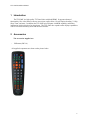
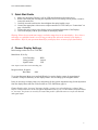
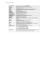
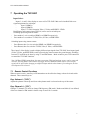
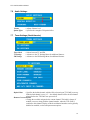
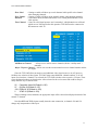
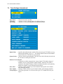
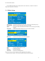
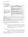
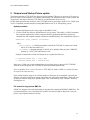
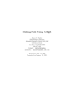
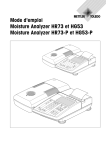
Pioneer TV/FM Tuner card with Dual HDMI
TVP-500F
Installation Manual
Manual# 050523
Model: TVP-500F
205 Commercial Court
Morganville, NJ 07751
www.auroramultimedia.com
TVP-500F Installation Manual
TABLE OF CONTENT
1
INTRODUCTION .................................................................................................................................2
2
ACCESSORIES .....................................................................................................................................2
3
QUICK START GUIDE .......................................................................................................................3
4
PIONEER DISPLAY SETTINGS........................................................................................................3
5
CONNECTIONS ...................................................................................................................................4
5.1
5.2
A/V CONNECTORS ............................................................................................................................4
RF CONNECTOR ................................................................................................................................4
6
SUPPORTED IR TRANSMITTER(S) AND BASIC KEY FUNCTIONS .......................................5
7
OPERATING THE TVP-500F.............................................................................................................7
7.1
7.2
7.3
7.4
7.5
7.6
7.7
7.8
7.9
7.10
7.11
REMOTE CONTROL FUNCTIONS ........................................................................................................7
MENU STRUCTURE ...........................................................................................................................8
MAIN MENU:....................................................................................................................................8
GENERAL SETTINGS .........................................................................................................................9
VIDEO SETTINGS ..............................................................................................................................9
AUDIO SETTINGS ............................................................................................................................10
TUNER SETTINGS (NORTH AMERICA).............................................................................................10
TUNER SETTINGS (INTERNATIONAL) ..............................................................................................12
FM RADIO SETTINGS......................................................................................................................14
CC SETTINGS .................................................................................................................................15
V-CHIP SETTINGS ...........................................................................................................................15
8
TROUBLESHOOTING......................................................................................................................16
9
FIRMWARE AND STARTUP PICTURE UPDATE.......................................................................17
10
RS-232 PROTOCOL.......................................................................................................................18
11
SPECIFICATIONS .........................................................................................................................21
11.1
11.2
11.3
11.4
APPLICABLE SIGNALS .....................................................................................................................21
CONNECTION TERMINALS ...............................................................................................................21
DIMENSIONS ...................................................................................................................................21
WEIGHT ..........................................................................................................................................21
12
LIMITED LIFETIME WARRANTY............................................................................................22
13
FCC PART 15 STATEMENT ........................................................................................................23
TVP-500F Installation Manual
1 Introduction
The TVP-500F is a high quality TV Tuner/Scaler with dual HDMI. It supports advanced
functionality, like video format /scan rate conversions, audio effects, Closed Caption decoding, V-Chip,
Sleep Timer, and more. In addition the TVP-500F has a FM tuner with RDS capability and station
information which is displayed on the plasma. The TVP-500F also expands on the displays capabilities
with its own internal menu systems and advanced features.
2 Accessories
The accessories supplied are:
-
IR Remote (IRC-10)
All supplied components are shown on the picture below:
2
TVP-500F Installation Manual
3 Quick Start Guide
1. Make sure the Pioneer Display is off (no LED) and disconnected from the power.
2. Remove the blank plate covering the expansion slot or if an existing card is present, it must be
removed from the slot.
3. Carefully insert the card into the slot and tighten the spring loaded screws.
4. Connect the appropriate video sources to input connectors of TVP-500F (see “Connections” on
page 4 for details).
5. Connect the power source to the display (refer to Operating Instructions of the Display).
6. Turn on the display with the power button on the display remote.
Warning: Please keep in mind static images can lead to image burn in on some displays. Never leave a
still image on a phosphor based screen for long periods of time unless the intensity of the display is
turned down. Refer to your operations manual for you display device to assure proper functionality.
4 Pioneer Display Settings
Initial settings on the first use of TVP-500F:
Main Menu Æ Set Up:
-
Color Decoding:
Clamp position:
Signal Format:
RGB
Locked
525P
Note: Inputs 3 and 4 have Color Decoding only.
Integrator Menu Æ Option:
Baud Rate:
9600
To get into Integrator Menu, press and hold Display key on the display remote for approximately
5 seconds. Then press Menu key on the display remote. This will bring up the Integrator Menu.
It may be necessary to adjust picture size and position for best picture alignment using Screen adjustment
from the display Menu and from Video Position on TVP-500F Menu (page 9).
Plasma Displays often "overscan" the image slightly; in some cases when displaying a channel, there
may be a narrow black bar on the left/right or top/bottom of the screen. Use the utilities mentioned above
to “overscan” the picture as necessary to ensure that picture is filled the entire screen for all channels
and signal inputs.
3
TVP-500F Installation Manual
5 Connections
5.1
A/V connectors
•
•
•
•
•
Composite Video input
S Video input
RGB/YPbPr input
2 HDMI inputs
Audio inputs for Video, S Video, and RGB/YPbPr
Example of interconnections for a display device, TVP-500F, DVD/VCR (or other source of video),
and TV antenna or cable is shown below. Note that standard RCA cables for audio and video connections,
standard S-Video cable, or RF antenna cables are not supplied with the TVP-500F.
5.2
RF connector
The coaxial connector (ANT) of TVP-500F is RF signal input – either aerial or cable TV, UHF/VHF,
if the TVP-500F shall be used as TV tuner. The other is for FM antenna reception.
4
TVP-500F Installation Manual
6 Supported IR transmitter(s) and basic key functions
The TVP-500F is controlled using an IR remote controller. It utilizes IR receiver of the display via
the built in IR sensor of the display.
The TVP-500F unit is compatible with the Aurora IRC-10 remote transmitter(s) below (see Fig.1).
TVP
Plasma
CC/TT
EDS
VIDEO
POWER
SLEEP
MUTE
SVIDEO RGB/YPbPr
FM
VOL
INFO
CH
TV
SELECT
MENU
1
2
3
4
5
6
7
8
9
LAST
SET
0
P1
P2
P3
P4
P5
P6
P7
P8
P9
P10
P11
P12
Presets
IRC-10
Fig. 1
For details of the TVP-500F operation refer to the corresponding chapter of this document. Below is
a brief description of the remote transmitter and the keys used for control of the TVP-500F.
5
TVP-500F Installation Manual
IR Remote
TVP
PLASMA
POWER
CC/TT
EDS
SLEEP
TV INPUT
FM INPUT
VIDEO INPUT
S-VIDEO INPUT
RGB/YPbPr INPUT
CHANNEL+/VOLUME +/MUTE
ARROWS
MENU
SELECT
INFO
SET
LAST
PRESET KEYS
0..9, DIGITS
Function
Selects to control the TVP-500F functions
Selects to control functions specific to the plasma
Toggles Power on/off
Enables/Disables Closed Captioning or Teletext (if available)
Enables/Disables Extended Data Service (if available)
Sets Sleep Timer
Selects TV Antenna as source
Selects FM Antenna as source
Selects Composite Video as source
Selects S-Video as source
Selects RGB or YPbPr as source
Changes TV channel or FM frequency up/down
Adjusts volume level up/down
Toggles the volume mute on/off
Moves the cursor up/down, selects or changes contents when Menu
is active.
Displays the menu and exists from the menus
Selects option in menu
Sets contents or changes in dialog panels
Displays current channel, input and output formats
Pressing this and one of the Preset buttons within 1.5 seconds will
store the current channel (TV) or station (FM)
Return to the last saved channel
P1 – P12: Selects the stored preset for TV or FM
P1 – Also used as Red for Teletext
P4 – Also used as Green for Teletext
P7 – Also used as Yellow for Teletext
P10 – Also used as Blue for Teletext
Directly enters channel number (TV) or FM frequency (FM) to switch
to. It is also used to enter the page numbers for Teletext.
6
TVP-500F Installation Manual
7 Operating the TVP-500F
Input Select:
Inputs 3, 4, and 5 of the display are reserved for TVP-500F if this card is installed. Below are
signal assignments for each input:
Input 3: HDMI A
Input 4: HDMI B
Input 5: TV/FM, Composite Video, S Video, and RGBHV / YPbPr.
Both Pioneer and Aurora remotes (IRC-10) can be used to switch inputs.
Switching input using Pioneer remote:
- Press number 3 or 4 to switch to HDMI A or HDMI B respectively.
- Press number 5 to switch to TV/FM, Video, S Video, or RGB/YPbPr.
Switching inputs using Aurora remote:
- Press Plasma, then 3 or 4 to switch to HDMI A or HDMI B respectively.
- Press Plasma, then 5 to switch to TV/FM, Video, S Video, or RGB/YPbPr.
Since input 5 of the display is used to display different input signals from TVP-500F, these input signals
(Video, S Video, and RGB/YPbPr) can be selected using Aurora remote (the green buttons). Switching
between TV and FM can be done by using TV and FM buttons. Make certain to press TVP button first
to control the TVP-500F functions.
Note: RGB and YPbPr inputs share the same connection (VGA) and only one source can be connected
at a time. Pressing RGB / YPbPr button will toggle between RGB and YPbPr inputs. The last input
signal will be saved when changing to a different input and when this button is pressed again, the last
saved input will be selected.
7.1
Remote Control Functions
When no menu is active, usual keys of IR transmitter can be utilized to change volume level and switch
channels. These control keys are:
Key: Volume+/- (”VOL”)
Adjusts the plasmas volume up and down when plasma mode is selected on the top of the remote.
Key: Channel +/- (“CH”)
Changes TV channel (TV mode) or change FM frequency (FM mode). Number and label (if was defined)
of the new channel or FM station is shown at top of screen for 5 seconds.
7
TVP-500F Installation Manual
Keys: 0-9
Dialog: “SWITCH TO” or “NEW FM FREQUENCY” – enter new channel number or FM frequency,
several digits can be entered if necessary. Channel or FM frequency is switched to after a 3 seconds
timeout (since the most recent digit is entered) or after pressing Select button.
Key: Menu
Display the main menu. See the Menu Structure chapter.
Key: Select
Enter selections for the menu.
Key: Power
Switch plasma power on or off when the plasma mode on top of the remote is selected.
7.2
Menu Structure
The menu structure allows controllability of various aspects of TVP-500F configuration.
For all menus, Up/Down arrows move the cursor (yellow “selection” highlight) up/down. Select
button will select the current submenu/option and finishes text entry (passwords, channel labels, etc.).
Left/right arrows change the currently active option, if possible.
When in “text edit” dialog (e.g., channel label editing), left/right arrows move the cursor left/right,
up/down arrows change the character at the cursor.
7.3
Main Menu:
The Main Menu displays all sub-menus that will be discussed in more detail in the subsequent
chapters.
Note: when existing from the Main Menu, a 3 to 5 seconds delay is needed before the next IR
command (from the remote) is sent out.
8
TVP-500F Installation Manual
7.4
General Settings
This menu allows control of various “general” aspects of TVP-500F behavior.
A/V Input
– Selects input signals for input 5 of the plasma.
Current time – Sets the current time.
Timer On
– Sets the turn on time of the plasma and allows it to be enabled and disabled.
Timer Off
– Sets the turn off time of the plasma and allows it to be enabled and disabled.
Sleep timer
– Sets sleep timer.
7.5
Video Settings
Brightness
Contrast
Color
Startup Logo
Timer Logo
Video Position
-- Adjusts the brightness of the picture.
-- Adjusts the contrast of the picture.
-- Adjusts color saturation (0 corresponds to grayscale picture).
-- Enables/Disables “logo” picture display after TVP-500F is on.
-- Sets time (in seconds) for which the logo will be displayed after the TVP-500 is
on.
-- Opens the “Video position” submenu, allowing control of picture size and
position on screen.
9
TVP-500F Installation Manual
7.6
Audio Settings
Volume
Spatial Effect
7.7
-- Adjusts Volume level
-- Specifies the strength of 3D-spatial effect
Tuner Settings (North America)
Tuner Mode
TV Settings
FM Settings
-- Selects between TV and FM
-- Advances to the TV Settings Menu for additional features.
-- Advances to the FM Settings Menu for additional features.
Default Chan
-- Specifies the default channel, which will be selected upon TVP-500F power-up.
If this default channel is set to “0” -- the default channel will be the last channel
selected before the TVP-500F was powered off.
Rename Current Channel
-- Change the text label assigned to the current channel. This label is shown (if
enabled) on screen, along with the channel number, when the TVP-500F is
switched to this channel. Display of labels and channel numbers can be globally
disabled on enabled, see the subsequent menu options.
10
TVP-500F Installation Manual
Show Label
-- Setting to enable will show up to an 8 character label specific to the channel
when changing channels.
Show Number -- Setting to enable will show up the channel number when changing channels.
Standard
-- Select tuner mode (channels allocation) to use, among broadcast and several
cable options.
Tune Channels -- Scans for valid signal presence and “remembers” which channels are valid and
which are not. Note that before this operation TVP-500F must be connected to
RF-antenna or cable TV.
Add/Remove Channels
-- Allows user to add or remove channels (edit the “validity mask”)
manually.
Map A/V Input to Channel -- Allows user to make an association between a channel number and the
AV inputs.
Since the TVP-500F allows to attach several additional video signal sources to its AV inputs, to
facilitate user selection of these inputs TVP-500F maps some additional “channel numbers” to its AV
inputs. So when these “channels” are selected, the TVP-500F switches to the respective AV input. These
reserved channel numbers are based on the values selected in the service menu and could be setup in
many different ways as shown below.
26 - Composite video IN (Default is 126)
97 - S-Video IN (Default is 127)
108 - RGB+HV IN (Default is 128)
2 - YPbPr IN (Default is 129)
When switching to those channels, the appropriate input will be selected and displayed instead of the
normal TV channel.
Note that RGB and YPbPr inputs actually share the same connection, so channels 128 and 129
change only interpretation of this input.
11
TVP-500F Installation Manual
7.8
Tuner Settings (International)
Tuner Mode
TV Settings
FM Settings
-- Selects between TV and FM
-- Advances to the TV Settings Menu for additional features.
-- Advances to the FM Settings Menu for additional features.
Default Chan
-- Specifies the default channel, which will be selected upon TVP-500F power-up.
If this default channel is set to “0” -- the default channel will be the last channel
selected before the TVP-500F was powered off.
System (Scaler) -- Allows selection signal standards. PAL B/G, PAL D/K, SECAM, PAL M, PAL
N, and Auto are among the selections.
Rename Current Channel
-- Change the text label assigned to the current channel. This label is shown (if
enabled) on screen, along with the channel number, when the TVP-500F is
switched to this channel. Display of labels and channel numbers can be globally
disabled on enabled, see the subsequent menu options.
Show Label
-- Setting to enable will show up to an 8 character label specific to the channel
when changing channels.
Show Number -- Setting to enable will show up the channel number when changing channels.
Country/Region -- Select the region that is or is closest to the type of TV standards used in your
region.
12
TVP-500F Installation Manual
Tune Channels (Manual Tuning) -- Scans for valid signal presence and “remembers” which
channels are valid and which are not. Note that before this operation TVP-500F
must be connected to RF-antenna or cable TV.
Add/Remove Channels
-- Allows user to add or remove channels (edit the “validity mask”)
manually.
Map A/V Input to Channel -- Allows user to make an association between a channel number and the
AV inputs.
Since the TVP-500F allows to attach several additional video signal sources to its AV inputs, to
facilitate user selection of these inputs TVP-500F maps some additional “channel numbers” to its AV
inputs. So when these “channels” are selected, the TVP-500F switches to the respective AV input. These
reserved channel numbers are based on the values selected in the service menu and could be setup in
many different ways as shown below.
26 - Composite video IN (Default is 126)
97 - S-Video IN (Default is 127)
108 - RGB+HV IN (Default is 128)
2 - YPbPr IN (Default is 129)
When switching to those channels, the appropriate input will be selected and displayed instead of the
normal TV channel.
13
TVP-500F Installation Manual
Note that RGB and YPbPr inputs actually share the same connection, so channels 128 and 129
change only interpretation of this input.
7.9
FM Radio Settings
Default Station -- Specifies the default preset which will be selected upon TVP-500F power-up.
Current Station -- Shows the current radio station tuned by the TVP-500F.
Region
-- Sets the area of the world which the TVP-500F is to be used for proper decoding
of signal.
Display RDS
-- Enables/Disable Radio Display Services for a station if available.
RDS Colors
-- Selects the color scheme for the RDS information.
Station
Name
Frequency
Auto Search
-- Sets Preset Station number (1 to 12).
-- Labels Preset Station.
-- Sets Preset frequency.
-- Searches for valid FM stations.
There are two ways to set Preset Stations for FM using Modify Preset Stations:
1 – Directly enter the frequency. Then set Preset number and name this Preset Station.
14
TVP-500F Installation Manual
2 – Use Auto Search: press ‘Up/Down’ arrow to select Auto Search. Press ‘Select’ to start. Searching will
stop once a station is detected. If it is a desired station, set Preset number and name for this Preset. Press
‘Select’ again to start searching for the next available station.
7.10 CC Settings
This menu controls Closed Caption decoder – CC signal type, and CC text color.
CC State
Foreground
Background
-- Enables/Disables Closed Captioned.
-- Sets foreground color for CC text.
-- Set background color for CC text.
7.11 V-Chip Settings
This menu configures V-Chip parental control system.
V-Chip Limit
-- Sets the threshold for program content indicator. Content rated as set in this
option (and below) can be viewed using the TV. Content rated above the setting
is rejected (red screen with message is shown).
Unrated Chan. -- Enables/Disables the viewing of “unrated” channels. Off=Do not allow viewing.
*- A user cannot change or reset password. Instead, to change the V-Chip limit user must enter the
V-Chip password.
If the password is reset, the user is prompted to enter new password on his/her first access to V-Chip
limit. For all subsequent accesses the user will have to use the password that was specified during the first
access. In the event the password is forgotten the V-Chip settings can reset by holding the enter button
for 5 sec. When prompted for the password enter right, left, right, left, enter and it will be reset to default
values.
15
TVP-500F Installation Manual
8 Troubleshooting
Symptom
Key on remote is pressed but
nothing happens
No RS-232 communication
RDS Info does not display
Cannot switch to a particular TV
channel using channel +/browse keys.
Checks
See if the upper LED of TVP-500F is fast-blinking while
pressing any key and aiming remote at IR sensor on
Plasma Display. If it is not -– check the batteries in the
remote.
Make sure the remote is in TVP mode (by pressing TVP
button on the upper left corner of the remote).
After existing the Main Menu, make sure there is a 3 to 5
seconds delay before any IR is sent out.
Check baud rate is set to 9600. Cable may need to be
nulled.
Poor reception will cause dropped characters from the RDS.
Also, not all stations broadcast RDS.
The channel is selectable by browsing keys only if it is
marked as “valid”. To be marked as “valid” the channel must
have a good TV signal during the “Tune Channel” operation.
Repeat the Tune Channel (making sure aerial/cable
connection is good). Also the channel validity can be edited
manually.
The two LEDs located on the TVP-500F indicate the current state of TVP-500F and may be useful for
troubleshooting.
During the startup (after powering on) the LEDs blink as the unit goes through self-test procedures and
firmware booting. If, after connecting the power, LEDs do not show any activity, then probably there are
problems with the power supply.
If the LEDs blink in alternative pattern -- upper/lower/upper/lower/etc – then the bootblock is active and
no valid main firmware is detected or it’s somehow corrupted. This can happen if, for instance, the
preceding firmware update procedure was aborted for some reason. The bootblock waits for the new
firmware upload, see the “Firmware update” section of this document.
During the normal functioning of TVP-500F (when a valid firmware is loaded and self-test and startup
procedures are finished, which takes about 2 seconds), the LED functions are:
Upper LED:
•
•
Flashes for 50ms once in 6 seconds when TVP-500F is attached to power supply, but
is in “Power Off” (“sleep”) state. Flashes for 50ms once in 3 seconds when TVP500F is in “Power On” state. This activity can be overridden by other activities of
the same LED.
Blinks fast when IR signal are detected. This can be used to see whether TVP-500F
receives any IR control packets or not. This does not mean that TVP-500F
recognizes any IR command.
Lower LED:
•
Switches ON when a control packet is sent through the RS-232. Switched OFF when
a valid reply to the control packet is received back. Therefore, if this LED is ON for
a long time, probably there are problems with the Panel Connection (or Panel power
supply).
The upper LED has also another purpose – if the TVP-500F encounters an internal irrecoverable error, it
stops all activities and starts blinking the upper LED in series (series of blinks, then a longer delay, then
the series of blinks is repeated, so on).
16
TVP-500F Installation Manual
9 Firmware and Startup Picture update
The internal software of TVP-500F (the firmware) can be updated. This may be necessary to fix errors in
previous releases of the firmware, or to enhance functionality. The similar procedure is used to update the
“logo picture” that can be shown by TVP-500F for a predefined time after power on.
For the update procedure the serial port of the TVP-500F must be connected to the RS-232 (“COM”) port
of a PC-compatible personal computer, running MS-Windows 98, 2k, or XP operating system.
Update procedure
1. Connect the Plasma to a PC using a 9pin-to-9pin RS232 cable.
2. Use the AXLdr.Exe utility to upload firmware or logo picture. This utility is a Win32 command
line (console) application. It can be run from within any application that allows specifying
command line (the simplest example is Windows Start\Run dialog). The command line syntax is:
AXLdr.Exe <port_number> <filename>
where
<port_number> is a COM port number to which the TVP-500F is connected (1-based,
that is, for COM1 this number is 1).
<filename> is the path and name of the file to be uploaded. Must be either *.BMP file
(bitmap) or *.ATF (TVP-500F firmware) file.
Example command line to load new bitmap file or to update the Firmware:
C:\TVP500F\AXLdr.Exe 1 logo1.bmp
C:\TVP500F\AXLdr.Exe 1 TVP500F.ATF
In this case, COM1 port is used to upload the new logo (logo1.bmp) or the new FW (TVP500F).
After the successful update, the TVP-500F firmware will restart automatically.
Note: to upload a file or a newer Firmware to TVP-500F, the loader (AXLdr.exe) and the file must
be stored in the same directory.
If the loaded firmware image is not valid (its header or checksum do not match the expected), this
firmware will not be loaded upon startup. Instead, the unit will remain in bootblock, which will wait
for the new firmware image to be uploaded again. This is indicated by LEDs “alternate” blinking
low/high/low/etc.
File format for logo picture BMP file
AXLdr.Exe supports conversion and loading of standard 24-bit unpacked RGB MS *.BMP files. The
recommended picture size is 852x480 pixels (width is 852 pixels, height is 480 pixels). Only one
picture can be uploaded and used as logo.
17
TVP-500F Installation Manual
10 RS-232 Protocol
Baud Rate: 9600 8N1
? IS A QUERY COMMAND
! IS A COMMAND
~ IS A RESPONSE
(Does not have to be Case Sensitive)
(Does not have to be Case Sensitive)
(ALL RESPONSES ARE CAPITALS)
<CR> is 0D hex or 13 decimal
!KEY_LEFT<CR>
!KEY_RIGHT<CR>
!KEY_UP<CR>
!KEY_DOWN<CR>
!KEY_SEL<CR>
!KEY_CH-<CR>
!KEY_CH+<CR>
!KEY_LAST<CR>
!KEY_0<CR>
!KEY_1<CR>
!KEY_2<CR>
!KEY_3<CR>
!KEY_4<CR>
!KEY_5<CR>
!KEY_6<CR>
!KEY_7<CR>
!KEY_8<CR>
!KEY_9<CR>
!KEY_SET<CR>
!KEY_P1<CR>
!KEY_P2<CR>
!KEY_P3<CR>
!KEY_P4<CR>
!KEY_P5<CR>
!KEY_P6<CR>
!KEY_P7<CR>
!KEY_P8<CR>
!KEY_P9<CR>
!KEY_P10<CR>
!KEY_P11<CR>
!KEY_P12<CR>
!KEY_MUTE<CR>
!KEY_TV<CR>
!KEY_FM<CR>
!KEY_VID<CR>
!KEY_SVID<CR>
!KEY_RGB<CR>
!KEY_MENU<CR>
!KEY_INFO<CR>
!KEY_CC<CR>
!KEY_EDS<CR>
Left
Right
Up arrow key
Down arrow key
Select
Channel Down
`Channel Up
Toggles between the last 2 channels selected
0
1
2
3
4
5
6
7
8
9
Set button for presets
Preset 1
Preset 2
Preset 3
Preset 4
Preset 5
Preset 6
Preset 7
Preset 8
Preset 9
Preset 10
Preset 11
Preset 12
Volume mute
TV Source Selection
FM Source Selection
Video Source Selection
S-Video Source Selection
RGB/YPbPr Source Selection
MENU
Info
Closed Captioning
Extended Data Services
18
TVP-500F Installation Manual
!KEY_RED<CR>
!KEY_GREEN<CR>
!KEY_YELLOW<CR>
!KEY_BLUE<CR>
!KEY_TTX_ONOFF<CR>
!KEY_TRANSPARENT<CR>
?MCH<CR>
Teletext Red Key
Teletext Green Key
Teletext Yellow Key
Teletext Blue Key
Teletext On/Off toggle Key
Teletext Transparent Key
Query Main Channel Responds with ~MCH002<CR> for
channel 2.
!MCHxxx<CR>
Main TV Channel change !MCH025<CR> for channel 25. xxx =
001 to 125
?MIN<CR>
Main Input Query responds with ~MTV<CR> or ~MFM<CR>
!FCHxxxx<CR>
FM Channel Selection. !FCH0987<CR> for 98.7fm.
?FCH<CR>
Query FM Channel responds with ~FCH0987<CR> for 98.7fm.
?VER<CR>
Version Query responds with ~VER 1.00<CR> if version 1.00
was present.
!CC1<CR>
Closed Caption 1 selection
!CC2<CR>
Closed Caption 2 selection
!CCOFF<CR>
Closed Caption Off selection
?CC<CR>
Query Closed Caption responds with either ~CC1<CR>,
~CC2<CR>, ~CCOFF<CR>
?AFC<CR>
responds with ~AFCxx<CR> xx=2 digit ASCII decimal
equivalent
Bit 7 - AFCWIN 1 = inside AFC Window 0 = Outside AFC Window
Bit 6 - VIFL 1 = Video IF Level High
0 = Video IF Level Low
Bit 5 - FMIFL 1 = fm IF Level High
0 = fm IF Level Low
Bits D4-D1 (AFC4-AFC1) Read the 4 bits separate of the other bits for easy use. eg. (afc & 0x1E)
then shift the bits 1 place to the right. This will give you a value of 0x00 to 0x0F. Follow the chart
below to determine the signal.
Bit4
0
0
0
0
0
0
0
0
1
1
1
1
1
1
1
1
Bit3
1
1
1
1
0
0
0
0
1
1
1
1
0
0
0
0
Bit2
1
1
0
0
1
1
0
0
1
1
0
0
1
1
0
0
Bit1
1
0
1
0
1
0
1
0
1
0
1
0
1
0
1
0
-187.5kHz
-162.5kHz
-137.5kHz
-112.5kHz
-87.5kHz
-62.5kHz
-37.5kHz
-12.5kHz
+12.5kHz
+37.5kHz
+62.5kHz
+87.5kHz
+112.5kHz
+137.5kHz
+162.5kHz
+187.5kHz
Bit 0 -PONR 1 = Power on reset after supply breakdown 0 = After a successful reading of the status
register
!LOGOON<CR>
!LOGOOFF<CR>
!LOGOTIMER%%<CR>
Enable Logo /Bitmap
Disable Logo / Bitmap
Set Logo display time when unit is first turned on
19
TVP-500F Installation Manual
?LOGOSTATUS<CR>
?LOGOTIMER<CR>
Reports back the logo status
Current logo timeout
!CxxxFxxxxx<CR>
!C002F05525<CR>
TV Channel Frequency setup for International version.
Set channel 2 to a freq of 55.25MHz.
General Info
Unless otherwise noted all valid commands are echoed back if properly received unless the “***”
address is used.
When Main TV or FM channel is changed via remote or contact closure, the RS232 is updated by
sending a ~MCHxxx<CR> or ~FCHxxxx<CR> response as long as the address is zero.
When Volume is changed via remote or contact closure, the RS232 is updated by sending a
~VOLxx<CR> response
Invalid commands will reply with ~ERROR<CR> as long as the address is zero.
Convert the multi-digit ASCII decimal representation response to a true hexadecimal value. Ex. xx =
13 (0x31, 0x33) turn this into 0D. The bit information is once the ASCII to hexadecimal conversion
has been done.
20
TVP-500F Installation Manual
11 Specifications
11.1 Applicable signals
Output format:
•
•
NTSC system (RF and AV inputs): RGB-HV 525p (480p)
PAL/SECAM system (RF and AV inputs): RGB-HV 576p
Inputs:
•
RF Tuner (North America - NTCS) and FM
Receiving RF signals – US Standard Air, US Standard Cable, Cable HRC, Cable IRC
TV Frequency Range: 55.25 to 801.25 MHz, 31.25 or 62.5KHz fine tune
FM Frequency Range: 76.00 to 108.00 MHz, 50KHz fine tune
•
RF Tuner (International – PAL/SECAM) and FM
TV Frequency Range: 48.25 to 855.25 MHz, 31.25/50.0, or 62.5KHz fine tune
FM Frequency Range: 76.00 to 108.00 MHz, 50KHz fine tune
•
Composite Video
Impedance: 75 ohms
Typical Input Level: 1.0V peak-peak into 75 ohms
•
S-Video
Impedance: 75 ohms
Typical Input Level: 1.0v peak-peak into 75 ohms
•
RGB-HV/YPbPr
Supported resolutions:
RGB-HV: VGA 60Hz, SVGA 60Hz, and XGA 60Hz
YPbPr: 480i, 480p (NTSC system) or 576i, 576p (PAL/SECAM system)
•
Supported audio standards: auto-detection, BTSC-STEREO, BTSC-MONO+SAP
11.2 Connection terminals
•
•
•
•
•
•
•
Composite Video IN (RCA)
S Video IN (4 pin Mini - DIN)
RGB+HV / YPbPr IN – 15-pin female VGA-compatible connector.
TV (aerial) IN – RF UHF/VHF (F Type connector for NTSC and IEC for PAL/SECAM)
FM (aerial) IN – RF (F type connector for NTSC and IEC for PAL/SECAM)
HDMI IN
Audio stereo IN (RCA)
11.3 Dimensions
Height x Depth x Length: 1.09” x 5.45’ x 11.87’
11.4 Weight
Approximately .55 lbs for TVP-500F unit and 1.5 lbs with all accessories and box
21
TVP-500F Installation Manual
12 Limited Lifetime Warranty
Aurora Multimedia Corp. (“Manufacturer”) warrants that this product is free of defects in both materials
and workmanship for the product lifetime as defined herein for parts and labor from date of purchase.
This Limited Lifetime warranty covers products purchased in the year of 2003 and after. Product lifetime
is defined as 7 years from discontinuance of product. Motorized mechanical parts (Hard Drives, DVD,
etc), remotes and cables are covered for a period of 1 year. Supplied batteries are not covered by this
warranty. During the warranty period, and upon proof of purchase, the product will be repaired or
replaced (with same or similar model) at our option without charge for parts or labor for the specified
product lifetime warranty period.
This warranty shall not apply if any of the following:
A) The product has been damaged by negligence, accident, lightning, water, act-of-God or mishandling;
or,
B) The product has not been operated in accordance with procedures specified in operating instructions:
or,
C) The product has been repaired and or altered by other than manufacturer or authorized service center;
or,
D) The product's original serial number has been modified or removed: or,
E) External equipment other than supplied by manufacturer, in determination of manufacturer, shall have
affected the performance, safety or reliability of the product.
F) Part(s) are no longer available for product.
In the event that the product needs repair or replacement during the specified warranty period, product
should be shipped back to Manufacturer at Purchaser's expense. Repaired or replaced product shall be
returned to Purchaser by standard shipping methods at Manufacturer's discretion. Express shipping will
be at the expense of the Purchaser. If Purchaser resides outside the contiguous US, return shipping shall
be at Purchaser's expense.
No other warranty, express or implied other than Manufacturer's shall apply.
Manufacturer does not assume any responsibility for consequential damages, expenses or loss of revenue
or property, inconvenience or interruption in operation experienced by the customer due to a malfunction
of the purchased equipment. No warranty service performed on any product shall extend the applicable
warranty period.
This warranty does not cover damage to the equipment during shipping and Manufacturer assumes no
responsibility for such damage.
This product warranty extends to the original purchaser only and will be null and void upon any
assignment or transfer.
22
TVP-500F Installation Manual
13 FCC Part 15 Statement
RADIO AND TELEVISION INTERFERENCE
This equipment has been tested and found to comply with the limits for a Class B digital device, pursuant to Part 15
of the FCC rules. These limits are designed to provide reasonable protection against harmful interference in a
residential installation. This equipment generates, uses and can radiate radio frequency energy and, if not installed
and used in accordance with the instructions, may cause harmful interference to radio communications. However,
there is no guarantee that interference will not occur in a particular installation. If this equipment does cause
harmful interference to radio or television reception, which can be determined by turning the equipment off and on,
the user is encouraged to try to correct the interference by one or more of the following measures:
- Reorient or relocate the receiving antenna.
- Increase the separation between the equipment and the receiver.
- Connect the equipment into an outlet on a circuit different from that to which the receiver is connected.
- Consult the dealer or an experienced radio/TV technician for help.
You may also find helpful the following booklet, prepared by the FCC: "How to Identify and Resolve Radio-TV
Interference Problems." This booklet is available from the U.S. Government Printing Office, Washington D.C.
20402.
Changes and Modifications not expressly approved by the manufacturer or registrant of this equipment can void
your authority to operate this equipment under Federal Communications Commissions rules.
In order to maintain compliance with FCC regulations shielded cables must be used with this equipment. Operation
with non-approved equipment or unshielded cables is likely to result in interference to radio & television re
23