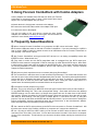
1
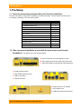
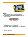
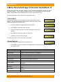
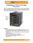
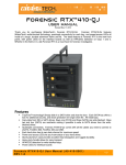
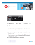
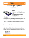
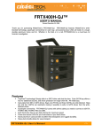
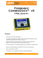
Forensic
ComboDock™ v5
User Manual
Revised September 17, 2012
Features
•
Dual mode: Write-block and Read/write
•
Four separate host attachment options (USB 3.0, FireWire 800, FireWire 400, and
eSATA) for compatibility with virtually any computer
•
Multiple LEDs indicate operational status, including disk activity, hidden area
detection, error state, and the status of power input and output
•
LCD menu allows user to configure settings and view information on attached drives
•
Detects and indicates hidden areas (HPAs or DCOs) found on hard drives
•
Able to create HPAs and DCOs
•
All-aluminum case for rugged durability and excellent heat dissipation
Forensic ComboDock v5 User Manual A9-000-0041 REV 1.0
-1-
CRU-WiebeTech
Table of Contents
1. Pre-Setup
2
1.1 Forensic ComboDock Accessories
2
1.2 Identifying Parts
3
2. Setup
4
3. Menu Structure and Usage of Forensic ComboDock v5
5
3.1 Select Mode
5
3.2 View Drive Info
5
3.3 View Dock Info
6
3.4 HPA/DCO Auto
6
3.5 Create HPA/DCO
6
4. USB Mode Switch
7
5. Use with Combo Adapters
8
6. Frequently Asked Questions
8
7. Technical Specifications
9
Forensic Device User Advisory
We recommend that you perform a final check on this product.
Prior to first use, please verify that the write-blocking function of this product is working properly. This is
easily done: attach a known good formatted drive, and verify that the drive mounts properly on your
computer. Use a drive that has data on it that you are willing to overwrite. Transfer files to the drive. The
files will appear to transfer to the drive. Thereafter, unmount the drive and remount the drive. The files
that you wrote to the drive should not appear after the drive is remounted. If they do appear, there is a
problem with your forensic device, and you should contact our support department for further instructions.
CRU support may be reached at:
(800) 260-9800 (toll free)
(360) 816-1836 (fax)
You can also contact us online through www.cru-dataport.com
Forensic ComboDock v5 User Manual A9-000-0041 REV 1.0
-2-
CRU-WiebeTech
1. Pre-Setup
1.1 Check the accessories packaged with your Forensic ComboDock
Forensic ComboDock v5 ships with everything you need to get started. Please contact CRU if any items
are missing or damaged. The box should contain:
Contains
Number
Forensic ComboDock unit
AC adapter & power cord
USB 3.0 cable
FireWire 800 cable
FireWire 400 cable
eSATA cable
1
1
1
1
1
1
SATA drive attachment cable
IDE cable
Molex mini-fit to legacy power cable
Metal drive plate
Packet of screws and bumpers
Quick Start Guide and Warranty Info
1
1
1
1
1
1
1.2 Take a moment to familiarize yourself with the parts of your new Forensic
ComboDock. This will aid you in the remaining steps.
A eSATA connector for connecting SATA drives
B 4-pin square connector for power cable to the drive
C 40-pin IDE header for external IDE cable attachment
D FireWire 400 connector
E dual FireWire 800 connectors
F USB 3.0 connector
G eSATA connector
H Power input from AC adapter
I SATA power input
J USB mode switch (see section 4)
Forensic ComboDock v5 User Manual A9-000-0041 REV 1.0
-3-
CRU-WiebeTech
K Write Block Indicator LED (green)
L Error LED (red)
M HDD access LED (amber)
N HPA/DCO Indication LED (green)
O LCD screen
P Navigation buttons
Q Power switch
R Power output status LED (green)
S Power input status LED (green)
2. Setup
a) Attach protective metal drive plate to your 3.5″ hard drive. (This step is optional.) The purpose of
the bottom plate is to provide protection to your drive electronics and aid heat dissipation.
b) If attaching an IDE/PATA drive, configure the jumpers on the rear of the drive. The drive must
be set to the Master setting. Consult the instructions for your drive (some drives display configuration
information on the drive’s label).
Rear of hard drive
IDE interface
Jumper
Pins
Power
c) Connect Forensic ComboDock to the drive (or adapter) using either the IDE ribbon cable for
IDE drives or the SATA data/power cable for SATA drives.
d) If using an adapter, connect the drive to the adapter.
e) Attach the power cable to Forensic ComboDock and to the drive. For SATA drives, the power
cable and data cable are combined into a single SATA drive interface.
f)
Connect the eSATA, FireWire or USB cable from your computer into the corresponding port
on Forensic ComboDock.
g) Provide power to Forensic ComboDock. Use either the included AC adapter or you can connect a
SATA power cable from inside a computer case. This is useful if you wish to access a drive inside a
computer without removing it first.
h) Turn on the power switch. The connected drive will power up and Forensic ComboDock’s main
menu will appear on the LCD screen.
You are now ready to use Forensic ComboDock to access the drive.
Forensic ComboDock v5 User Manual A9-000-0041 REV 1.0
-4-
CRU-WiebeTech
3. Menu Structure/Usage of Forensic ComboDock v5
Use the LCD and 4-button navigation interface to view information about the drive and dock or adjust
HPA/DCO handling. On the 4-button navigation interface, UP and DOWN allow scrolling through
options, while ENTER selects and BACK exits or returns to the previous screen.
Forensic ComboDock’s menu consists of the following screens:
3.1 Select Mode
Every time you switch Forensic ComboDock on, the “Select Mode” screen
displays. You can switch between write-blocked or read-write modes. Writeblocked will always be the default mode.
•
Press UP or DOWN to toggle between the two modes.
•
Press ENTER to select the mode you want.
•
If you select read-write mode, you will be prompted to confirm your
selection.
•
Press ENTER to select the mode you wish to use.
•
A “Standby” screen will briefly display.
SELECT MODE:
WRITE-BLOCKED
>
SELECT MODE:
READ-WRITE
>
ARE YOU SURE?
< NO
YES >
Standby
Forensic Combo Dock is now in the mode you selected.
3.2 View Drive Info
VIEW DRIVE INFO
This screen displays information about the attached drive.
•
>
Press ENTER, and then use the UP or DOWN buttons to scroll through and view the following
info about the drive.
Appearance on LCD
Disk Temp
Capacity (MB)
Manufacturer
Explanation
Temperature of the attached drive, measured in degrees Celsius.
Capacity of the HDD, measured in megabytes.
Manufacturing company name of the HDD.
Model number
Serial number
Firmware Rev
HPA size (MB)
Model number of the HDD.
Serial number of the HDD.
Firmware revision number of the HDD.
The size of the Host Protected Area of the HDD, measured in megabytes.
The size of the Device Configuration Overlay of the HDD, measured in
megabytes.
Displays the S.M.A.R.T. health status of the drive.
S.M.A.R.T. information on how many times the drive has spun up and spun
down.
S.M.A.R.T. information on how many power on/off cycles the drive has
underwent.
Number of bad sectors reported by the drive.
DCO size (MB)
Disk health
Start/Stops
Power cycles
Bad sectors
Forensic ComboDock v5 User Manual A9-000-0041 REV 1.0
-5-
CRU-WiebeTech
3.3 View Dock Info
This screen displays information about your Forensic ComboDock unit.
VIEW DOCK INFO:
>
•
From the “View Drive Info” screen, press the UP or DOWN buttons to get to the “View Dock Info”
screen. Press ENTER.
•
Use the UP or DOWN buttons to scroll through and view the following info about Forensic
ComboDock.
Appearance on LCD
Product Name
Unique ID#
Firmware ver. #
Explanation
Brand name of the product (e.g. “Forensic ComboDock”).
A specific, unique number assigned to the unit for identification, akin to a
serial number.
Firmware version currently installed on the Forensic ComboDock product.
3.4 HPA/DCO Auto
This screen allows you to configure the way Forensic ComboDock will automatically handle hidden areas
it detects on drives during power up.
HPA/DCO AUTO
•
•
>
From the “View Drive Info” screen, press the UP or DOWN buttons to get
to the “HPA/DCO Auto” screen. Press ENTER.
• Press UP or DOWN to scroll through the four ways Forensic ComboDock can handle HPAs
and DCOs.
1)
Ignore all - Detects and indicates their presence, but does not
remove them.
HPA/DCO AUTO
IGNORE ALL
2)
Temp Unlock HPA - Temporarily remove HPA only.
HPA/DCO AUTO
TEMP UNLOCK HPA >
3)
Perm Unlock HPA - Permanently remove HPA only
HPA/DCO AUTO
PERM UNLOCK HPA >
4)
Unlock All - Permanently remove any HPA or DCO
Press ENTER when your desired mode appears on the LED. Forensic
ComboDock will then set your desired mode as the default.
3.5 Create HPA/DCO
>
HPA/DCO AUTO
UNLOCK ALL
>
UNLOCK ALL
NOW DEFAULT
SUPPORTED IN
You can create an HPA or DCO on the attached drive only if you are in ReadR/W MODE ONLY
Write mode. If you try to create an HPA/DCO in Write-Blocked mode, the screen
will display “SUPPORTED IN R/W MODE ONLY.” To create an HPA/DCO, cycle power on the unit and
switch to Read-Write mode.
3.5.1 Set DCO Size
This option is only available if no HPA exists on the drive. It allows you to set a new size for DCO (Device
Configuration Overlay). Each drive can only have one such area. Use the navigation buttons to select its
size. The disk capacity available to a computer will be reduced by this amount. A value of zero means
no DCO. Values exceeding available capacity are not accepted.
•
From the “View Drive Info” screen, press the UP or DOWN buttons to get
to the “Create HPA/DCO” screen. Press ENTER.
CREATE HPA/DCO:
•
Press UP or DOWN to toggle between “Set HPA size” and “Set DCO
size” screens. When “Set DCO Size” displays, press ENTER.
SET HPA SIZE
Forensic ComboDock v5 User Manual A9-000-0041 REV 1.0
>
>
-6-
CRU-WiebeTech
•
A notification will appear on the screen that continuing will end any data
transfer. Make sure no data is being written to or read from the drive,
then press ENTER.
WILL END ANY
DATA XFER
•
Use the UP, DOWN, BACK and ENTER buttons to enter the size of the
DCO that you want. Press ENTER.
DCO SIZE (MB):
00000000>
•
Forensic ComboDock will ask you to confirm. If not sure, Press BACK. If
sure, press ENTER.
HPA SIZE (MB):
ARE YOU SURE?
•
Forensic ComboDock will then create the DCO. When complete, you
will be notified to cycle power on the unit.
CREATING DCO
CYCLE POWER NOW
>
>
After Forensic ComboDock is turned off and back on, the DCO exists on the connected drive.
3.5.2 Set HPA Size
From this screen, you can set a new size for HPA (Host Protected Area). Each drive can only have one
such area. Use the navigation buttons to select its size. The disk capacity available to a computer will be
reduced by this amount. A value of zero means no HPA. Values exceeding available capacity are not
accepted.
•
From the “View Drive Info” screen, press the UP or DOWN buttons to get
to the “Create HPA/DCO” screen. Press ENTER.
CREATE HPA/DCO:
•
Press UP or DOWN to toggle between “Set HPA size” and “Set DCO size”
screens. When “Set HPA Size” displays, press ENTER.
SET HPA SIZE
•
A notification will appear on the screen that continuing will end any data
transfer. If this is OK, press ENTER.
WILL END ANY
DATA XFER
•
Use the UP, DOWN, BACK and ENTER buttons to enter the size of the
HPA that you want. Press ENTER.
HPA SIZE (MB):
00000000>
•
Forensic ComboDock will ask you to confirm. If not sure, Press BACK.
If sure, press ENTER.
HPA SIZE (MB):
ARE YOU SURE?
•
Forensic ComboDock will then create the HPA. When complete, you will
be notified to cycle power on the unit.
CREATING HPA
CYCLE POWER NOW
>
>
>
>
After Forensic ComboDock is turned off and back on, the HPA exists on the connected drive.
4. USB Mode Switch
There are two USB modes on Forensic ComboDock.
•
USB 3.0 Mode: Use this mode when Forensic ComboDock is connected to a USB 3.0 port on
your computer with a USB 3.0 cable (such as the cable included with the product). If Forensic
ComboDock is used with a USB 2.0 port or cable and it is switched to USB Normal mode, the
dock will not function correctly.
•
USB 2.0 Mode: This mode ensures that Forensic ComboDock is backwards-compatible with
USB 2.0. In this mode you can use any cable or USB port type, but it will operate at USB 2.0
speed. USB Admin mode should also be used when using CRU applications (such as Forensic
Software Utility) to update the dock.
Forensic ComboDock v5 User Manual A9-000-0041 REV 1.0
-7-
CRU-WiebeTech
5. Using Forensic ComboDock with Combo Adapters
Combo Adapters are available from CRU that can allow your Forensic
ComboDock to access all kinds of drives. Follow these three simple
steps to use a Combo Adapter with your dock:
A. Attach the dock’s 4-wire power connector to the adapter.
B. Connect the dock’s IDE ribbon cable to the adapter’s IDE pins.
C. Connect the drive to the adapter.
You are now ready to use your dock to access the drive. Combo
Adapters are available for a variety of drive types. See the WiebeTech
website for more details (www.wiebetech.com).
6. Frequently Asked Questions
Q: When I connect Forensic ComboDock to my computer via USB, it does not function. Why?
A: Check the USB mode switch on the side of Forensic ComboDock. If you are connecting to a USB 2.0
host or using a USB 2.0 cable, the switch must be set to USB Admin mode for Forensic ComboDock to
work properly. See section 4 above.
Q: My Forensic ComboDock works great with SATA drives but I am having compatibility issues with
IDE/PATA drives. What should I do?
A: First check to make sure the SATA power/data cable is unplugged from the SATA output port.
IDE/PATA drives cannot be recognized if a SATA connection is made with the SATA output. Next check
to make sure the 4-pin power cable is plugged into the IDE/PATA drive. If the power and host connection
are securely attached to Forensic ComboDock, then the IDE cable may be faulty. Contact Technical
Support for further instructions.
Q: Why does my dock experience errors or unmount during long file transfers?
A: The environment in which the dock is used can affect its performance. The surface that the dock and
drive are set upon may not allow heat to dissipate away from the units. The bottom plate supplied with the
product will help to dissipate heat away from the hard drive and dock. If placed on a non-conductive
surface, the drive or dock may suffer heat related failures. After cooling, the units usually return to a
useable state. Occasionally these heat-related failures can be permanent.
Q: How should I set the jumpers on my drive?
A: Note: This is only necessary for IDE/PATA drives (the type of drive that has a 40-pin data interface).
Try the MASTER setting first. This is the recommended setting. Some hard drives have two different
MASTER settings: one for when there is a SLAVE drive present and one for when there is NO SLAVE
drive present. Choose the setting for NO SLAVE present. There may be some drives that will not work
with either of these settings. The next choice is CABLE SELECT. If this does not work, try using NO
jumpers. This may be the same as MASTER with NO SLAVE present. If you're unsure how to change the
jumper configuration, check the manual that came with your hard drive, or the manufacturer's website.
Some drives also have the information printed on the label.
Q: Can I attach an eSATA drive enclosure to the SATA drive connection on Forensic ComboDock? Will
this allow me to access it via FireWire or USB on my computer as if it were a bare hard drive?
A: Yes. By using an eSATA to eSATA cable, you can connect an eSATA drive enclosure to the eSATA
connector on the “drive side” of the dock. You can then connect the “host side” of the dock to a computer
via any of the connections. This should give you access to the drive without requiring its removal from its
housing.
Forensic ComboDock v5 User Manual A9-000-0041 REV 1.0
-8-
CRU-WiebeTech
7. Technical Specifications
Product Name
Drive Compatibility
Host Interfaces
Power Supply
Operating System
Unit Dimensions
Shipping Weight
Compliance
Support
Forensic ComboDock v5
• 2.5-inch & 3.5-inch SATA drives
• 3.5-inch IDE/PATA drives
• Additional types using optional adapters
• USB 3.0 (USB 2.0 when switch is set to USB 2.0 mode)
• eSATA 3G
• FireWire 800 (two ports, daisy-chainable)
• FireWire 400
Input: 100-240VAC; Output: +12V 3.5A
• Windows 7, Vista, XP
• Mac OS X
• Linux distributions supporting the desired connection type
75 mm x 110 mm x 27 mm
4 pounds, including accessories
CE, FCC
We don’t expect anything to go wrong with your product. But if it does, Tech Support is
standing by and ready to help. Contact us through www.cru-dataport.com or call
(800) 260-9800.
ComboDock and WiebeTech are trademarks of CRU Acquisitions Group, LLC. Other marks are the property of their respective
owners.
© 2008, 2012 CRU Acquisitions Group, LLC. All rights reserved.
Limited Product Warranty
CRU-DataPort (CRU) warrants Forensic ComboDock to be free of significant defects in material and workmanship for a period of
two years from the original date of purchase. CRU’s warranty is nontransferable and is limited to the original purchaser.
Limitation of Liability
The warranties set forth in this agreement replace all other warranties. CRU expressly disclaims all other warranties, including but
not limited to, the implied warranties of merchantability and fitness for a particular purpose and non-infringement of third-party rights
with respect to the documentation and hardware. No CRU dealer, agent or employee is authorized to make any modification,
extension, or addition to this warranty. In no event will CRU or its suppliers be liable for any costs of procurement of substitute
products or services, lost profits, loss of information or data, computer malfunction, or any other special, indirect, consequential, or
incidental damages arising in any way out of the sale of, use of, or inability to use any CRU product or service, even if CRU has
been advised of the possibility of such damages. In no case shall CRU’s liability exceed the actual money paid for the products at
issue. CRU reserves the right to make modifications and additions to this product without notice or taking on additional liability.
FCC Compliance Statement: “This device complies with Part 15 of the FCC rules. Operation is subject to the following two
conditions: (1) This device may not cause harmful interference, and (2) this device must accept any interference received, including
interference that may cause undesired operation.”
This equipment has been tested and found to comply with the limits for a Class A digital device, pursuant to Part 15 of the FCC
Rules. These limits are designed to provide reasonable protection against harmful interference when the equipment is operated in a
home or commercial environment. This equipment generates, uses, and can radiate radio frequency energy and, if not installed and
used in accordance with the instruction manual, may cause harmful interference to radio communications.
In the event that you experience Radio Frequency Interference, you should take the following steps to resolve the problem:
1) Ensure that the case of your attached drive is grounded.
2) Use a data cable with RFI reducing ferrites on each end.
3) Use a power supply with an RFI reducing ferrite approximately 5 inches from the DC plug.
4) Reorient or relocate the receiving antenna.
Tested to comply
with FCC standards
FOR OFFICE OR
COMMERCIALUSE
Forensic ComboDock v5 User Manual A9-000-0041 REV 1.0
-9-