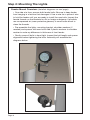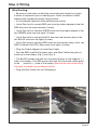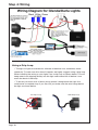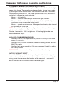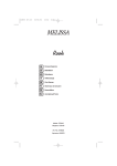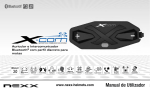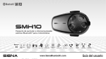
1
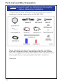
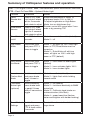
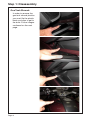
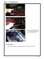
Installation Manual
BMW K1600GT
Glenda / Darla
LED Light Kit
Dimmable
Parts List and Bike Preparation
Please be sure to read our instructions thoroughly
before attempting installation.
• Check Parts list below with your kit to be sure all parts are handy. If
something is missing, please call us at (916) 852-7029.
Please take the time to review the included instructions. Installation
of the new Clearwater Lights is straightforward. But, be sure to follow
some of the suggestions to keep the installation safe and reliable. If you
have any questions or comments, please feel free to contact us.
Thank you!
Page 2
Summary of Installation
1.
2.
3.
4.
5.
6.
7.
Open body panels
8.
Secure wires, making sure they won’t get caught in the suspension or
steering column.
9.
Attach power lines to battery and replace the fuse.
Mount the lights and brackets.
Disassamble the side panel.
Remove fuse from Clearwater Lights wiring harness
Mount the wiring harness to a secure location.
Connect the CANopener
Connect the lights and CANopener to their corresponding plugs on the
wiring harness.
IMPORTANT THINGS TO REMEMBER!
The engine needs to be running for lights to work
Brake light not to exceed 1AMP
CANbus controller fuse 7.5 AMP (located under seat)
Abbreviations
TSC = Turn Signal Cancel
WW = WonderWheel (BMW multifunction controller)
FTP = Flash To Pass
OBL = Optional Brake Light
Page 3
Summary of CANopener features and operation
TSC = Turn Signal Cancel WW = WonderWheel (BMW multifunction controller)
FTP = Flash To Pass OBL = Optional Brake Light
Function
Command
Modes
Darla/
Glenda dimmer
Press(TSC), then
hold control wheel
left for 2 seconds
and rotate to adjust
Erica/Krista
dimmer
Press(TSC), then
hold control wheel
right for 2 seconds
and rotate to adjust
Rotate WonderWheel to select 10
brightness levels (10% to 100%)
To adjust brightness on High Beam
Mode, turn on high beam first
Dimmer control will cancel after 2 seconds or by pressing TSC
Erica/Krista
on/off
Hold TSC for 2
seconds
Mode 1 – on and dimmable (default)
Mode 2 – off
High Beam
Mode
Hold brake lever
and press FTP 3
times to toggle
Mode 1 – all lights on 100% with high
beam or FTP, Erica/Krista must be
turned on
Mode 2 – Erica/Krista off with low
beam, all lights on 100% with high
beam or FTP (default)
Horn Activation Mode
Hold brake lever
and press TSC 3
times to toggle
Mode 1 – horn does not affect lights
(default)
Mode 2 – horn activates lights 100%
Mode 3 – horn strobes lights
Hazard
Flasher Alert
Mode
Hold hazard switch Mode 1 – no flash (default)
Mode 2 – lights flash while holding
and press brake
hazard switch
lever 3 times to
toggle
Clearwater
Brake Light
(optional)
While stationary,
press brake lever
or pedal 5 times
within 5 seconds to
toggle
Reset Default Hold left turn
Settings
signal and press
FTP 6 times within
6 seconds
Page 4
Mode 1 – off (default)
Mode 2 – functions identically to BMW
brake light
Mode 3 – California legal strobe on
brake activation (4Hz flash)
Mode 4 – speed sensitive (flashes
faster and brighter with harder braking)
Reset all functions to the default settings above
Mouting CANopener
• Remove the seat from the bike and set aside.
• Locate the module under the seat, unplug the wiring harness from it and
plug your Clearwater CANopener in it’s place. Then plug the wiring harness
into the CANopener.
• Secure the CANopener to the plastic inner fender with provided Velcro
strip. Be sure to clean any dirt or dust from area before affixing the
CANopener.
• DO NOT mount the CANopener on top or touch the module.
Module
CANopener
Page 5
Step 1: Disassembly
Gas Tank Shroud:
In order to remove the
gas tank shroud plastics
you must flip the plastic
back as shown to get to
the bolts. Follow images
continued on the next
page.
Page 6
Step 1: Disassembly
Your bike should look like
this after removing the gas
tank shroud plastics.
Re-Assembly:
• Follow the directions in reverse order to reassemble your bike.
Page 7
Step 2: Mounting The Lights
Fender Mount Overview: (detailed diagrams on next page)
• One side at a time, remove both fender bolts. Be sure to keep fender
from hanging in a fashion that damages it. Use a wire tie or piece of wire
to hold the fender until you are ready to install the new bolts. Inspect the
female threads on the brackets for dirt or foreign substance. If possible,
use compressed air (wear protective glasses) or small bottle brush to
clean the threads.
• Pre-assemble the lights, mounting bracket, shoulder washers (if
needed) and spacers with new bolts. Add 2 plastic washers to shoulder
washer to make up difference in thickness of front fender.
• Gently screw all bolts in hand tight. Inspect the bolt length and spacer
alignment before tightening the bolts. Assembly will resemble the
diagrams below.
Page 8
Step 4: Wiring
Wire Routing:
• Be sure to route wires so that they cannot become tangled or caught
in either a suspension part or steering part. Check movement of both
steering and suspension before riding the bike.
• It is sometimes helpful to follow existing wire routing.
• Use a Posi-lock to connect RED wire from the trident adapter to the thin
RED wire from the relay harness (2 wires).
• Use a Posi-twist to connect GREEN wire from the trident adapter to the
two GREEN wires from the lights (3 wires).
• Use a Posi-twist to connect BLACK wire from the harness relay to the
two BLACK wire from the lights (3 wires).
• Use a Posi-twist to connect RED wire from the harness relay to the two
RED in Glenda, WHITE in Darla wires from lights (3 wires).
• Plug the Trident Adapter into the Data Cable
• Run the RED and BLACK power wire, and Data Cable along the air
intake up to the battery. (Fig.1) and (Fig. 2)
• The BLACK power wire with the ring terminal goes to the negative ( - )
side of the battery. The RED power wire with the inline fuse holder goes
to the
positive ( + ) side of the battery. Remove the fuse while wiring
the lights to prevent any accidental shorts.
• Plug the Data Cable into the CANopener.
Fig. 1
Fig. 2
Page 9
Step 4: Wiring
Using a Drip Loop
• Though our lights are sealed for ultimate all weather use, sometimes water
sneaks by. To make sure this doesn’t happen, we highly suggest using a drip loop.
When installing the wiring to your lights, use a drip loop as shown below. This will
keep water from dripping directly into the light and instead fall off before it can
reach the back of the body.
• To do this just leave a bit of extra wiring and let it hang below the light. You
could make a complete loop if you like, but just make sure the wire hangs below
the light as shown below.
No Drip Loop
Page 10
With Drip Loop
Step 5: Aligning the Lights
Alignment:
• Ask an assistant to help you
with this procedure. Make sure the
bike is on level ground and have
an assistant sit on the bike. With a
right angle board or object, position
the board on the floor and slide it
up to the light. The goal is to adjust
the lights so that the light is level
with the ground. Passengers and
luggage may alter the alignment
of the light, so further adjustments
may be needed. You may find that a
slight downward angle (5 degrees)
is helpful.
Posi-Products Installation Instructions:
A
B
C
Posi-twist (A):
1. Strip all wires to be inserted 1/2”.
2. Twist all wires together before inserting into the Posi-twist.
3. Completely unscrew the top from the Posi-twist.
4. Feed the twisted wires through the bottom portion of the Posi-twist.
5. Attach the top and tighten, while ensuring the wires do not slip out of
the bottom of the Posi-twist.
Posi-lock (B):
1. Remove both ends from the Posi-lock.
2. Strip wire 1/2” and insert into bottom portion of the Posi-lock.
3. Hand tighten the Posi-lock onto bottom portion with wire, repeat for other side.
Page 11
Clearwater CANopener operation and features
Summary of features
1.
Clearwater Lights dimming feature
• Independent dimming of two sets of Clearwater lights using
BMW WonderWheel (handlebar mounted rotary dimmer included for nonWonderWheel bikes)
• Brightness adjustable in 10 steps from 10-100%
2. Automatic Dimmer
• Programmable Clearwater lights dimmer setting compensates
automatically using the bike’s photocell
• Factory preset and programmable dimmers for day, night, and high
beam illumination
3. On/off function for Erica/Krista lights
• No separate switch required, uses factory turn signal cancel button
4. Horn Activation Mode
• Clearwater lights programmable to illuminate or strobe with horn
button (off road use only)
5. Hazard Flasher Alert Mode
• Clearwater lights programmable to strobe when holding the hazard
flasher button (off road use only)
6. High Beam Mode
• Clearwater Erica/Krista lights programmable to activate with high
beam or flash-to-pass button
7. Clearwater Brake Light Module (optional)
• Programmable LED brake module includes California-legal strobe
mode and speed sensitive mode
8. Auxiliary CANbus relay drives
• Auxiliary turn on (1/4 amp maximum) - YELLOW wire
• Auxiliary horn (1/4 amp maximum) - GRAY wire
• Auxiliary high beam relay drive (1/4 amp maximum) - GREEN wire
WARNING: Do not connect auxiliary accessories without a relay!
9. Factory Default Reset
• Reset all functions to the default settings
Page 12
Clearwater CANopener operation and features
DIMMING CONTROL (WonderWheel equipped bikes)
Two modulated brightness channels are adjustable using the
WonderWheel:
• Each channel is programmable for ten brightness settings (10100%) in three different modes (day, night, and high beam). Settings
are stored in non-volatile memory, and will be remembered when
restarting the bike or disconnecting the battery. The dimmer is
programmed at the factory for the most useful day/night settings.
• To enter dimmer program, you now must first press the Turn Signal
Cancel (TSC) switch once before tilting the Wonderwheel Left or
Right for dimming. Press the WonderWheel to the LEFT for two
seconds to engage the Darla/Glenda channel dimmer, or press it
to the RIGHT for two seconds to engage the Erica/Krista channel
dimmer. The lights being adjusted will flash twice to confirm
programming mode. Adjust the output by rotating the WonderWheel.
• While adjusting the brightness mode, the second set of lights (if
installed) will automatically dim to their lowest setting in order to
easily observe the adjustment.
• Exit programming mode either by waiting for approximately two
seconds or pressing the turn signal cancel button. The lights will
flash once to confirm.
• Remember that each set of lights is adjustable for day, night and
high beam. Day and night settings are automatically selected by the
ambient light level reaching the bike’s photocell. To adjust the night
dimmer, simply cover the photocell at the top right corner of the dash
display using your hand or a piece of tape. Activate the high beam to
adjust the high beam setting.
WARNING: When configuring the dimmer, be sure that the WonderWheel
is not making adjustments to other functions of the onboard systems.
Turn off the entertainment system to prevent volume adjustment or
unwanted channel changes, and select the home screen on the GPS.
DIMMING CONTROL (non-WonderWheel bikes)
If the motorcycle does not have the GPS Prep Package
(WonderWheel), your light kit will come equipped with a handlebar
mounted analog/digital encoder knob for dimming control. Separate day
and night settings and the dual intensity dimmer will not be available.
ON/OFF FUNCTION FOR ERICA/KRISTA
The Erica/Krista lights can be manually deactivated. Toggle these
modes by holding the turn signal cancel button for two seconds.
• Mode 1 – on and dimmable (default)
• Mode 2 – off
Page 13
Clearwater CANopener operation and features
HORN ACTIVATION MODE
The Clearwater lights can be programmed for three different modes when
the horn button is pressed. Toggle these modes by holding the brake lever
and pressing the Turn Signal Cancel button three times. The brake and
Clearwater lights flash to indicate the mode selected:
• Mode 1 – horn does not affect lights (default)
• Mode 2 – horn activates lights 100%
• Mode 3 – horn strobes lights (if two sets of Clearwater lights are
installed, they will alternate flashing)
WARNING: The use of strobe mode may not be legal on public highways.
Check your local regulations. This mode is intended for parades and
escorts under certain conditions.
HAZARD FLASHER ALERT MODE
The Clearwater lights can be programmed to strobe when the hazard
flasher button on the left grip is held down. Toggle these modes by holding
down the hazard flasher button and pressing the brake lever three times:
• Mode 1 – OFF, no flash with emergency flasher button (default)
• Mode 2 – strobe with emergency flasher button held down (if two sets
of Clearwater lights are installed, they will alternate flashing)
NOTE: Pressing the hazard flasher button activates the turn signal flashers.
Cancel the flashers with another short press of the button.
WARNING: The use of strobe mode may not be legal on public highways.
Check your local regulations. This mode is intended for parades and
escorts under certain conditions.
HIGH BEAM MODE
The Erica/Krista lights can be programmed for two modes of
operation in conjunction with high beams. Toggle these modes by holding
the brake lever and pressing flash-to-pass three times:
• Mode 1 – all Clearwater lights turn on 100% when high beam or flashto-pass is pressed. Erica/Krista use the day/night dimmed setting on
low beam. Erica/Krista lights must be turned on. (default on ver 1.5 or
greater)
• Mode 2 – HIGH BEAM ACTIVATION. All Clearwater lights turn on
100% when high beam or flash-to-pass is pressed. Erica/Krista are
turned off with low beam. Erica/Kristas do NOT need to be turned on.
(default on ver 1.6 or greater)
Page 14
Clearwater CANopener operation and features
CLEARWATER BRAKE LIGHT MODULE (OPTIONAL)
A 1 AMP driver is provided for the optional Clearwater auxiliary brake light
license plate frame. There are four modes available. Toggle these modes
by pressing the brake lever or pedal five times while the bike is stationary.
The engine may be on or off. The brake lights will flash one, two, three or
four times to indicate the mode selected.
• Mode 1 – off (default).
• Mode 2 – functions identically to BMW brake light, no flash.
• Mode 3 – California legal strobe on brake activation (4Hz flash), then
continuous on as long as the brake is held.
• Mode 4 – speed sensitive mode. Bike speed and braking data is used
to modulate the flash rate.
NOTE: The auxiliary brake light is configured as an “always on” running
light at a reduced light level. When either the front or rear brake is
activated, it activates at 100% brightness. All flashing light modes are
deactivated below 5mph.
AUXILIARY CANBUS RELAY DRIVES
• Auxiliary turn on (1/4 amp maximum) Useful for turning on aux fuse
boxes or a PDM-60.
• Auxiliary horn (1/4 amp maximum) Useful for adding and aux air horn.
MUST use relay.
• Auxiliary high beam relay drive (1/4 amp maximum) Useful for adding
an aux high beam.
WARNING: Do not connect auxiliary accessories without a relay!
FACTORY DEFAULT RESET
To reset the CANopener to the factory settings, hold the left turn signal
switch and press the flash-to-pass button six times within six seconds. All
factory preset dimmer levels and modes will be selected. A successful
reset is indicated by five flashes of the Clearwater lights.
Page 15
Thank you for purchasing our Clearwater lights. We hope this product
will help make you a safer rider. Please feel free to send us comments
or suggestions at any time. We learn from you. Visit our website for more
exciting products. Ride safe!
Sincerely,
Glenn and the team at Clearwater.
The Clearwater Company - 11305 Sunrise Gold Circle, Unit D
Rancho Cordova, CA 95742
Phone: (916) 852-7029 | Fax: (916) 852-9410 | www.clearwaterlights.com
Version 1 | 8/11/14