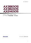
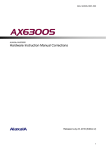
1
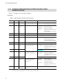
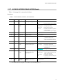
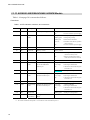
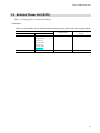
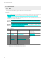
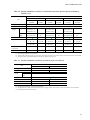
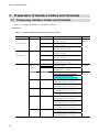
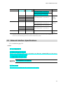
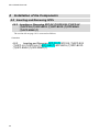
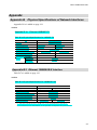
MA-7 AX36S-H001-50X ALAXALA AX3600S/AX2400S Hardware Instruction Manual Corrections Released July 23, 2010 (7th Edition) 1 MA-7 AX36S-H001-50X Preface This document contains corrections for the AX3600S/AX2400S Hardware Instruction Manual (© 2005, 2007 ALAXALA Networks Corporation. All rights reserved.). If you intend to use an AX2400S or AX3600S switch, please read this document carefully. This document applies to the following manual: No. 1 Manual Name ALAXALA AX3600S/AX2400S Hardware Instruction Manual Manual Number AX36S-H001-50 Trademarks y Ethernet is a product name of Xerox Corporation. y Windows is either a registered trademark or trademark of Microsoft Corporation in the United States and/or other countries. y Other company and product names are trademarks or registered trademarks of their respective owners. Note The information in this document is subject to change without notice. Edition history First edition: Second edition: Third edition: Fourth edition: Fifth edition: Sixth edition: Seventh edition: December 12, 2007 May 9, 2008 September 10, 2008 February 6, 2009 April 21, 2009 July 14, 2009 July 23, 2010 Copyright Copyright (C) 2007, 2010, ALAXALA Networks Corporation. All rights reserved. 2 MA-7 AX36S-H001-50X Contents Introduction .....................................................................................................................................4 1 Components Overview ................................................................................................................5 2 Preparation for Installation ......................................................................................................... 15 3 Preparation of Interface Cables and Terminals ............................................................................ 18 4 Installation of the Components ................................................................................................... 20 Appendix ...................................................................................................................................... 23 3 MA-7 AX36S-H001-50X Introduction Limits for Harmonic Current Emissions The list of devices that meet the standards for harmonic current emissions is corrected as follows: Corrections Products conforming to the JIS C 61000-3-2 standards for harmonic current emissions Conforming devices: AX-2430-24T (AX2430S-24T) AX-2430-24TE (AX2430S-24T) AX-2430-24T2X (AX2430S-24T2X) AX-2430-24T2XE (AX2430S-24T2X) AX-2430-48T (AX2430S-48T) AX-2430-48TE (AX2430S-48T) AX-2430-48T2X (AX2430S-48T2X) AX-2430-48T2XE (AX2430S-48T2X) AX-3630-24T (AX3630S-24T) AX-3630-24TE (AX3630S-24T) AX-3630-24T2X (AX3630S-24T2X) AX-3630-24T2XE (AX3630S-24T2X) AX-3630-24P (AX3630S-24P) AX-3630-24S2XW (AX3630S-24S2XW) AX-3630-24S2XWE (AX3630S-24S2XW) AX-3630-48TW (AX3630S-48TW) AX-3630-48TWE (AX3630S-48TW) AX-3630-48T2XW (AX3630S-48T2XW) AX-3630-48T2XWE (AX3630S-48T2XW) AX-3640-24T (AX3640S-24T) AX-3640-24TE (AX3640S-24T) AX-3640-24TW (AX3640S-24TW) AX-3640-24T2XW (AX3640S-24T2XW) AX-3640-24SW (AX3640S-24SW) AX-3640-24SWE (AX3640S-24SW) AX-3640-24S2XW (AX3640S-24S2XW) AX-3640-24S2XWE (AX3640S-24S2XW) AX-3640-48TW (AX3640S-48TW) AX-3640-48TWE (AX3640S-48TW) AX-3640-48T2XW (AX3640S-48T2XW) AX-3640-48T2XWE (AX3640S-48T2XW) AX-F2430-EPUA (EPU-A) AX-F2430-EPUB (EPU-B) 4 MA-7 AX36S-H001-50X 1 Components Overview 1.1 Main Device 1.1.1 AX2430S-24T/AX2430S-24TD/AX3630S-24T/AX3630S-24TD/AX3 640S-24T Models Table 1-2 on page 5 is corrected as follows: Corrections Table 1-2 LED indication, switches, and connectors Number (1) (2) Name PWR ST1 Type Green LED Green/Red LED Description Indicates power supply status Indicates device status Details Lit in green: Power on Off: Power off or failure in power supply Lit in green: Standby or operating Blinking green: Getting ready (startup) Blinking red: Partial failure in the device Lit in red: Fatal failure in the device (operation cannot continue) Off: Power off or failure in power supply (3) ST2 Green LED (Not used) Off (4) MC Connector Memory card slot Memory card slot (5) ACC Green LED Indicates memory card status Lit: Accessing the memory card (do not remove the memory card) Off: Memory card idle mode (memory cards can be inserted or removed) (6) CONSOLE Connector CONSOLE port RS-232C port to connect a console terminal (7) LINK Green/Orange LED Indicates the operating status of the SEP slot Ethernet port Lit in green: A link is established Lit in orange: Detecting line disturbances Off: Link failure or block when the green ST1 LED is lit Blinking green: Sending or receiving frames Indicates the operating status of Lit in green: A link is established the 10/100/1000BASE-T Ethernet port Blinking green: A link is established and frames are being sent or received (8) T/R Green LED (9) 1-24 Green/Orange LED (10) RESET Switch (momentary) Manual reset switch of the device*1 Lit in orange: Detecting line disturbances Off: Link failure or block when the green ST1 LED is lit Restarts the device *1: The switch is behind the front panel. Use a screwdriver with a small head to press it. 5 MA-7 AX36S-H001-50X 1.1.3 AX2430S-24T2X/AX2430S-24T2XD/AX3630S-24T2X/ AX3630S-24T2XD Table 1-7 on page 12 is corrected as follows: Corrections Table 1-7 LED indication, switches, and connectors Number (1) (2) Name PWR ST1 Type Green LED Green/Red LED Description Indicates power supply status Indicates device status Details Lit in green: Power on Off: Power off or failure in power supply Lit in green: Standby or operating Blinking green: Getting ready (startup) Blinking red: Partial failure in the device Lit in red: Fatal failure in the device (operation cannot continue) Off: Power off or failure in power supply (3) ST2 Green LED (Not used) Off (4) MC Connector Memory card slot Memory card slot (5) ACC Green LED Indicates memory card status Lit: Accessing the memory card (do not remove the memory card) Off: Memory card idle mode (memory cards can be inserted or removed) (6) CONSOLE Connector CONSOLE port RS-232C port to connect a console terminal (7) LINK Green/Orange LED Indicates the operating status of the SEP slot Ethernet port Lit in green: A link is established Lit in orange: Detecting line disturbances Off: Link failure or block when the green ST1 LED is lit Blinking green: Sending or receiving frames (8) T/R Green LED (9) LINK Green/Orange LED (10) T/R Green LED (11) 1-24 Green/Orange LED (12) RESET Switch (momentary) Indicates the operating status of the XFP slot Ethernet port Lit in green: A link is established Lit in orange: Detecting line disturbances Off: Link failure or block when the green ST1 LED is lit Blinking green: Sending or receiving frames Indicates the operating status of Lit in green: A link is established the 10/100/1000BASE-T Ethernet port Blinking green: A link is established and frames are being sent or received Manual reset switch of the device*1 Lit in orange: Detecting line disturbances Off: Link failure or block when the green ST1 LED is lit Restarts the device *1: The switch is behind the front panel. Use a screwdriver with a small head to press it. 6 MA-7 AX36S-H001-50X 1.1.5 AX3630S-24P Model Table 1-12 on page 20 is corrected as follows: Corrections Table 1-12 LED indication, switches, and connectors Number (1) (2) Name PWR ST1 Type Green LED Green/Red LED Description Indicates power supply status Indicates device status Details Lit in green: Power on Off: Power off or failure in power supply Lit in green: Standby or operating Blinking green: Getting ready (startup) Blinking red: Partial failure in the device Lit in red: Fatal failure in the device (operation cannot continue) Off: Power off or failure in power supply (3) ST2 Green LED (Not used) Off (4) MC Connector Memory card slot Memory card slot (5) ACC Green LED Indicates memory card status Lit: Accessing the memory card (do not remove the memory card) Off: Memory card idle mode (memory cards can be inserted or removed) (6) CONSOLE Connector CONSOLE port RS-232C port to connect a console terminal (7) LINK Green/Orange LED Indicates the operating status of the SEP slot Ethernet port Lit in green: A link is established Lit in orange: Detecting line disturbances Off: Link failure or block when the green ST1 LED is lit Blinking green: Sending or receiving frames (8) T/R Green LED (9) 1-24 Green/Orange LED (10) RESE Switch (momentary) Indicates the operating status of Lit in green: A link is established the 10/100/1000BASE-T Ethernet port Blinking green: A link is established and frames are being sent or received Manual reset switch of the device*1 Lit in orange: Detecting line disturbances Off: Link failure or block when the green ST1 LED is lit Restarts the device *1: The switch is behind the front panel. Use a screwdriver with a small head to press it. 7 MA-7 AX36S-H001-50X 1.1.6 AX2430S-48T/AX2430S-48TD Models Table 1-13 on page 23 is corrected as follows: Corrections Table 1-13 LED indication, switches, and connectors Number (1) (2) Name PWR ST1 Type Green LED Green/Red LED Description Indicates power supply status Indicates device status Details Lit in green: Power on Off: Power off or failure in power supply Lit in green: Standby or operating Blinking green: Getting ready (startup) Blinking red: Partial failure in the device Lit in red: Fatal failure in the device (operation cannot continue) Off: Power off or failure in power supply (3) ST2 Green LED (Not used) Off (4) MC Connector Memory card slot Memory card slot (5) ACC Green LED Indicates memory card status Lit: Accessing the memory card (do not remove the memory card) Off: Memory card idle mode (memory cards can be inserted or removed) (6) CONSOLE Connector CONSOLE port RS-232C port to connect a console terminal (7) LINK Green/Orange LED Indicates the operating status of the SEP slot Ethernet port Lit in green: A link is established Lit in orange: Detecting line disturbances Off: Link failure or block when the green ST1 LED is lit Blinking green: Sending or receiving frames (8) T/R Green LED (9) 1-48 Green/Orange LED (10) RESET Switch (momentary) Indicates the operating status of Lit in green: A link is established the 10/100/1000BASE-T Ethernet port Blinking green: A link is established and frames are being sent or received Manual reset switch of the device*1 Lit in orange: Detecting line disturbances Off: Link failure or block when the green ST1 LED is lit Restarts the device *1: The switch is behind the front panel. Use a screwdriver with a small head to press it. 8 MA-7 AX36S-H001-50X 1.1.7 AX3630S-48TW/AX3640S-48TW Models Table 1-14 on page 26 is corrected as follows: Corrections Table 1-14 LED indication, switches, and connectors Number (1) (2) Name PWR ST1 Type Green LED Green/Red LED Description Indicates power supply status Indicates device status Details Lit in green: Power on Off: Power off or failure in power supply Lit in green: Standby or operating Blinking green: Getting ready (startup) Blinking red: Partial failure in the device Lit in red: Fatal failure in the device (operation cannot continue) Off: Power off or failure in power supply (3) ST2 Green LED (Not used) Off (4) MC Connector Memory card slot Memory card slot (5) ACC Green LED Indicates memory card status Lit: Accessing the memory card (do not remove the memory card) Off: Memory card idle mode (memory cards can be inserted or removed) (6) CONSOLE Connector CONSOLE port RS-232C port to connect a console terminal (7) LINK Green/Orange LED Indicates the operating status of the SEP slot Ethernet port Lit in green: A link is established Lit in orange: Detecting line disturbances Off: Link failure or block when the green ST1 LED is lit Blinking green: Sending or receiving frames (8) T/R Green LED (9) 1-48 Green/Orange LED (10) RESET Switch (momentary) Indicates the operating status of Lit in green: A link is established the 10/100/1000BASE-T Ethernet port Blinking green: A link is established and frames are being sent or received Manual reset switch of the device*1 Lit in orange: Detecting line disturbances Off: Link failure or block when the green ST1 LED is lit Restarts the device *1: The switch is behind the front panel. Use a screwdriver with a small head to press it. 9 MA-7 AX36S-H001-50X 1.1.11 AX3630S-24S2XW/AX3640S-24S2XW Models Table 1-18 on page 38 is corrected as follows: Corrections Table 1-18 LED indication, switches, and connectors Number (1) (2) Name PWR ST1 Type Green LED Green/Red LED Description Indicates power supply status Indicates device status Details Lit in green: Power on Off: Power off or failure in power supply Lit in green: Standby or operating Blinking green: Getting ready (startup) Blinking red: Partial failure in the device Lit in red: Fatal failure in the device (operation cannot continue) Off: Power off or failure in power supply (3) ST2 Green LED (Not used) Off (4) MC Connector Memory card slot Memory card slot (5) ACC Green LED Indicates memory card status Lit: Accessing the memory card (do not remove the memory card) Off: Memory card idle mode (memory cards can be inserted or removed) (6) CONSOLE Connector CONSOLE port RS-232C port to connect a console terminal (7) LINK Green/Orange LED Indicates the operating status of Lit in green: A link is established the 10/100/1000BASE-T Ethernet port Lit in orange: Detecting line disturbances Off: Link failure or block when the green ST1 LED is lit Blinking green: Sending or receiving frames (8) T/R Green LED (9) LINK Green/Orange LED (10) T/R Green LED (11) LINK Green/Orange LED (12) T/R Green LED (13) RESET Switch (momentary) Indicates the operating status of the SEP slot Ethernet port Indicates the operating status of the XFP slot Ethernet port Manual reset switch of the device*1 Lit in green: A link is established Lit in orange: Detecting line disturbances Off: Link failure or block when the green ST1 LED is lit Blinking green: Sending or receiving frames Lit in green: A link is established Lit in orange: Detecting line disturbances Off: Link failure or block when the green ST1 LED is lit Blinking green: Sending or receiving frames Restarts the device *1: The switch is behind the front panel. Use a screwdriver with a small head to press it. 10 MA-7 AX36S-H001-50X 1.4 External Power Unit (EPU) Table 1-25 on page 50 is corrected as follows: Corrections Table 1-25 Compatibility of main devices with external power units (EPUs) and power supply modules Main Device Power Type AC power model Model Name AX2430S-24T Compatible EPU Compatible Power Supply Module EPU-A EPU-AM EPU-B EPU-BM AX2430S-24T2X AX2430S-48T AX2430S-48T2X AX3630S-24T AX3630S-24T2X AX3640S-24T AC power (PoE) model AX3630S-24P 11 MA-7 AX36S-H001-50X 1.7 Transceiver 1.7.1 SFP Descriptions of the SFP on pages 63 and 64 are corrected as follows: Corrections To use the SFP, mount it to the SFP slot of the main device. The SFP type can be identified by either of the following: y The shape and handle color of the SFP (except for the SFP-FX (T) and the SFP-SX (T)) y The label Note that the supported SFPs differ depending on the device. For compatibility between devices and SFPs, refer to Table 1-32 SFP list. To visually distinguish between the SFP-FX (T) and the SFP-SX (T), check the labels. When the SFP is mounted on the device, use the show port command to determine the SFP type from the displayed interface information. For details about the show port command, see 14. Ethernet in Software Manual Operation Command Reference Vol. 1. Table 1-32 SFP list Number 1 Module Name SFP-T (T) Interface Ethernet 10/100/1000BASE-T (PoE not supported) Supported Models AX3630S-24S2XW*1 AX3640S-24SW*1 AX3640S-24S2XW*1 1a SFP-FX (T) Ethernet 100BASE-FX AX3640S-24SW*1 AX3640S-24S2XW*1 2 SFP-SX (T) Gigabit Ethernet 1000BASE-SX 3 SFP-SX2 (T) Gigabit Ethernet 1000BASE-SX2 4 SFP-LX (T) Gigabit Ethernet 1000BASE-LX 5 SFP-LH (T) Gigabit Ethernet 1000BASE-LH 5a SFP-LHB (T) Gigabit Ethernet 1000BASE-LHB 6 SFP-BX1U (T) Gigabit Ethernet 1000BASE-BX10-U*2 7 SFP-BX1D (T) Gigabit Ethernet 1000BASE-BX10-D*2 8 SFP-BX4U (T) Gigabit Ethernet 1000BASE-BX40-U*3 9 SFP-BX4D (T) Gigabit Ethernet 1000BASE-BX40-D*3 *1: Connection can be established by using SFP slot ports 5 to 24. *2: 1000BASE-BX10-U and 1000BASE-BX10-D are paired when in use. *3: 1000BASE-BX40-U and 1000BASE-BX40-D are paired when in use. 12 All models of AX2400S and AX3600S series MA-7 AX36S-H001-50X SFPs (except for the SFP-T (T)) use lasers that are colorless and invisible. Do not look directly into the optical transmitter/receiver area. Do not attach other labels to the transceiver. The transceivers have labels to certify that they are standard products of the manufacturer and ALAXALA. These labels are attached so as not to interfere with heat radiation from the transceiver or with the mechanism to prevent dropping from the cage. Attaching a label to a part that interferes with heat radiation or the mechanism to prevent dropping from the cage might cause a failure in the transceiver or damage to the device. Make sure to use ALAXALA standard products, which have labels as shown in the figures. If nonstandard products are used, correct operation is not guaranteed. SFP-FX (T) is added as (1a) on page 64: Addition (1a) SFP-FX (T) Figure 1-67a External appearance (1) (2) (1) Label: Label color: (2) Handle color: ALAXALA SFP-FX (T) White Black SFP-FX (T) is supported by the following two models: AX3640S-24SW and AX3640S-24S2XW. 13 MA-7 AX36S-H001-50X SFP-LHB (T) is added as (5a) on page 65: Addition (5a) SFP-LHB (T) Figure 1-71a External appearance (1) (2) (1) Label: Label color: (2) Handle color: ALAXALA SFP-LHB (T) White Yellow-green 1.7.2 XFP The description in (2) XFP-LR (T) on page 69 is corrected as follows: Corrections (2) XFP-LR (T) Figure 1-77 External appearance zType A module zType B module (1) (1) (2) (2) (1) Label: AlaxalA XFP-LR (T) (2) Handle color: Blue Two types of XFP-LR are available: the type-A module and the type-B module. These two modules are functionally identical. 14 MA-7 AX36S-H001-50X 2 Preparation for Installation 2.2 Installation Conditions 2.2.1 General Installation Conditions Tables 2-1 to 2-3 and 2-5 to 2-7 on pages 73 to 77 are corrected as follows: Corrections Table 2-1 General installation conditions of AX2400S series main devices (AC or DC power models) Model Name Item AX2430S -24T AX2430S -24T2X AX2430S -48T Dimensions (W × D × H)*1 Weight*2 Input voltage 5 kg or less Rated AX2430S AX2430S -48T2X -24TD 445 × 380 × 43 mm 5.5 kg or less AX2430S -24T2XD 5 kg or less -48 V DC 90 to 127.2 V AC, 180 to 254.4 V AC -40 to -57 V DC Frequency 50/60 ± 3 Hz Maximum input current Maximum power consumption Maximum heat emission 5.5 kg or less Single phase 100 to 120 V AC, 200 to 240 V AC*3 Variation range AX2430S -48TD -- 0.8 A @ 100 V AC 0.9 A @ 100 V AC 1.2 A @ 100 V AC 1.3 A @ 100 V AC 1.5 A @ -48 V DC 1.7 A @ -48 V DC 2.5 A @ -48 V DC 0.4 A @ 200 V AC 0.5 A @ 200 V AC 0.6 A @ 200 V AC 0.7 A @ 200 V AC -- -- -- 74 W 88 W 118 W 130 W 69 W 80 W 118 W 267 kJ/h 317 kJ/h 425 kJ/h 468 kJ/h 249 kJ/h 288 kJ/h 425 kJ/h *1: Excluding the dimensions of connectors. *2: Weight of the main device only. The weights of cables, rack fixtures, memory cards, and transceivers are excluded. *3: The power supply cable bundled with the main device supports only 100 V AC. Table 2-2 General installation conditions of AX3630S series main devices (AC, AC (PoE), or DC power models) Model Name Item Dimensions (W × D × H)*1 AX3630S AX3630S -24T -24T2X 445 × 380 × 43 mm Weight*2 Input voltage AX3630S -24P 445 × 490 × 43 mm AX3630S AX3630S -24TD -24T2XD 445 × 380 × 43 mm 5 kg or less 8 kg or less 5 kg or less Rated Single phase 100 to 120 V AC, 200 to 240 V AC*3 Single phase 100 to 120 V AC -48 V DC Variation range 90 to 127.2 V AC, 180 to 254.4 V AC 90 to 127.2 V AC -40 to -57 V DC Frequency Maximum input current Maximum power consumption Maximum heat emission 50/60 ± 3 Hz -- 0.8 A @ 100 V AC 0.9 A @ 100 V AC 5.8 A @ 100 V AC 1.5 A @ -48 V DC 0.4 A @ 200 V AC 0.5 A @ 200 V AC -- -- 1.8 A @ -48 V DC -- 75 W 89 W 580 W 70 W 82 W 270 kJ/h 321 kJ/h 757 kJ/h*4 252 kJ/h 296 kJ/h *1: Excluding the dimensions of connectors. *2: Weight of the main device only. The weights of cables, rack fixtures, memory cards, and transceivers are excluded. *3: The power supply cable bundled with the main device supports only 100 V AC. 15 MA-7 AX36S-H001-50X *4: Heat emission of the main device only. Table 2-3 General installation conditions of AX3630S series main devices (power redundancy models) Model Name Item AX3630S-24S2XW PS-A01 mounted PS-D01 mounted Dimensions (W × D × H)*1 Weight AX3630S-48TW PS-A01 mounted PS-A01 mounted PS-D01 mounted Single phase -48 V DC 445 × 440 × 43 mm *2 9 kg or less Rated Input voltage AX3630S-48T2XW PS-D01 mounted Single phase -48 V DC 100 to 120 V AC, 200 to 240 V AC*3 Variation range 90 to 127.2 V AC, 180 to 254.4 V AC Single phase -48 V DC 100 to 120 V AC, 200 to 240 V AC*3 100 to 120 V AC, 200 to 240 V AC*3 -40 to -57 V DC 90 to 127.2 V AC, 180 to 254.4 V AC -40 to -57 V DC 90 to 127.2 V AC, 180 to 254.4 V AC -40 to -57 V DC Frequency 50/60 ± 3 Hz -- 50/60 ± 3 Hz -- 50/60 ± 3 Hz -- Maximum input current 1.0 A @ 100 V AC 1.8 A @ -48 V DC 1.4 A @ 100 V AC 2.6 A @ -48 V DC 1.5 A @ 100 V AC 2.8 A @ -48 V DC 0.5 A @ 200 V AC -- 0.7 A @ 200 V AC -- 0.8 A @ 200 V AC -- 92 W 85 W 134 W 124 W 143 W 133 W 332 kJ/h 306 kJ/h 483 kJ/h 447 kJ/h 515 kJ/h 479 kJ/h Maximum power consumption Maximum heat emission *1: Excluding the dimensions of connectors and handles. *2: Weight of the main device with two power units. The weights of cables, rack fixtures, memory cards, and transceivers are excluded. *3: The power supply cable bundled with the main device supports only 100 V AC. Table 2-5 General installation conditions of AX3640S series main devices (power redundancy models 1 of 2) Model Name Item AX3640S-24TW AX3640S-24T2XW PS-D01 PS-A01 PS-D01 PS-A01 PS-D01 mounted mounted mounted mounted mounted mounted Single phase -48 V DC Dimensions (W × D × H)*1 445 × 440 × 43 mm Weight*2 9 kg or less Rated Input voltage AX3640S-48TW PS-A01 Variation range Frequency Maximum input current Single phase -48 V DC Maximum heat emission -48 V DC 100 to 120 V AC, 100 to 120 V AC, 100 to 120 V AC, 200 to 240 V AC*3 200 to 240 V AC*3 200 to 240 V AC*3 90 to 127.2 V AC, 90 to 127.2 V AC, 90 to 127.2 V AC, -40 to -57 V DC -40 to -57 V DC 180 to 254.4 V AC 50/60 ± 3 Hz -- 50/60 ± 3 Hz -- 1.0 A 1.9 A 1.4 A 2.7 A @ 100 V AC @ -48 V DC @ 100 V AC @ -48 V DC 0.5 A -- 0.7 A -- -40 to -57 V DC 180 to 254.4 V AC 50/60 ± 3 Hz -- 0.9 A 1.6 A @ 100 V AC @ -48 V DC 0.5 A -- 180 to 254.4 V AC @ 200 V AC Maximum power consumption Single phase @ 200 V AC @ 200 V AC 85 W 75 W 100 W 90 W 135 W 125 W 306 kJ/h 270 kJ/h 360 kJ/h 324 kJ/h 486 kJ/h 450 kJ/h *1: Excluding the dimensions of connectors. *2: Weight of the main device with two power units. The weights of cables, rack fixtures, memory cards, and transceivers are excluded. *3: The power supply cable bundled with the main device supports only 100 V AC. 16 MA-7 AX36S-H001-50X Table 2-6 General installation conditions of AX3640S series main devices (power redundancy models 2 of 2) Model Name AX3640S-48T2XW Item AX3640S-24SW PS-D01 PS-A01 PS-D01 PS-A01 PS-D01 mounted mounted mounted mounted mounted mounted Single phase -48 V DC Dimensions (W × D × H)*1 445 × 440 × 43 mm Weight*2 9 kg or less Rated Input voltage AX3640S-24S2XW PS-A01 -48 V DC Single phase -48 V DC 100 to 120 V AC, 100 to 120 V AC, 100 to 120 V AC, 200 to 240 V AC*3 200 to 240 V AC*3 200 to 240 V AC*3 90 to 127.2 V AC, Variation range Single phase 180 to 254.4 V AC -40 to -57 V DC 50/60 ± 3 Hz -- 1.5 A Frequency 90 to 127.2 V AC, 180 to 254.4 V AC 180 to 254.4 V AC 50/60 ± 3 Hz -- 50/60 ± 3 Hz -- 2.9 A 0.9 A 1.6 A 1.0 A 1.9 A @ 100 V AC @ -48 V DC @ 100 V AC @ -48 V DC @ 100 V AC @ -48 V DC 0.8 A -- 0.5 A -- 0.5 A -- Maximum input current @ 200 V AC @ 200 V AC -40 to -57 V DC @ 200 V AC 145 W 135 W 85 W 75 W 100 W 90 W 522 kJ/h 486 kJ/h 306 kJ/h 270 kJ/h 360 kJ/h 324 kJ/h Maximum power consumption Maximum heat emission 90 to 127.2 V AC, -40 to -57 V DC *1: Excluding the dimensions of connectors. *2: Weight of the main device with two power units. The weights of cables, rack fixtures, memory cards, and transceivers are excluded. *3: The power supply cable bundled with the main device supports only 100 V AC. Table 2-7 General installation conditions of external power units (EPUs) Model Name Item EPU-A Dimensions (W × D × H)*1 Weight*2 Input voltage EPU-B 445 × 440 × 43 mm 12 kg or less Rated 9 kg or less Single phase 100 to 120 V AC 90 to 127.2 V AC Variation range Frequency 50/60 ± 3 Hz Maximum input current Maximum power consumption *3 Maximum heat emission 10.5 A @ 100 V AC 15.0 A @ 100 V AC 1,050 W 1,500 W 1,534 kJ/h 1,008 kJ/h *1: Excluding the dimensions of connectors and handles. *2: Weight of the unit with the maximum number of power supply modules. The weights of cables and rack fixtures are excluded. *3: Heat emission of the main device only. 17 MA-7 AX36S-H001-50X 3 Preparation of Interface Cables and Terminals 3.1 Connecting Interface Cables and Terminals Table 3-1 on pages 98 and 99 is corrected as follows: Corrections Table 3-1 Interface cables and terminal connection cables Port/Slot 10/100/1000BASE-T port Transceiver -- (PoE not supported) Interface Cable Connector 10BASE-T UTP cable RJ45 (Category 3 or higher) connector 100BASE-TX UTP cable (Category 5 or higher) 1000BASE-T UTP cable 10BASE-T UTP cable 100BASE-TX UTP cable (Enhanced Category 5 or higher) 10/100/1000BASE-T port -- (Category 5 or higher) (PoE supported) (Category 5 or higher) 1000BASE-T UTP cable (Enhanced Category 5 or higher) SFP Slot SFP-T (T) 10BASE-T (PoE not supported) 100BASE-TX SFP-FX (T) 100BASE-FX 1000BASE-T UTP cable (Category 5 or higher) Multiple-terminal mode optical fiber LC duplex (core/cladding diameter = 50 µm/125 µm) connector (core/cladding diameter = 62.5 µm/125 µm) 1000BASE-SX Multiple-terminal mode optical fiber (core/cladding diameter = 50 µm/125 µm) Multiple-terminal mode optical fiber (core/cladding diameter = 62.5 µm/125 µm) SFP-SX2 (T) 1000BASE-SX2 Multiple-terminal mode optical fiber (core/cladding diameter = 50 µm/125 µm) Multiple-terminal mode optical fiber (core/cladding diameter = 62.5 µm/125 µm) SFP-LX (T) 1000BASE-LX Multiple-terminal mode optical fiber*1 (core/cladding diameter = 50 µm/125 µm) Multiple-terminal mode optical fiber*1 (core/cladding diameter = 62.5 µm/125 µm) Single-terminal mode optical fiber (core/cladding diameter = 10 µm/125 µm) SFP-LH (T) 1000BASE-LH Single-terminal mode optical fiber (core/cladding diameter = 10 µm/125 µm) Single-terminal mode (DSF) optical fiber (core/cladding diameter = 8 µm/125 µm) 18 connector UTP cable (Enhanced Category 5 or higher) Multiple-terminal mode optical fiber SFP-SX (T) RJ45 MA-7 AX36S-H001-50X Port/Slot Transceiver SFP Slot SFP-LHB (T) Interface 1000BASE-LHB Cable Connector Single-terminal mode optical fiber (core/cladding diameter = 10 µm/125 µm) Single-terminal mode (DSF) optical fiber (core/cladding diameter = 8 µm/125 µm) XFP Slot SFP-BX1U (T) 1000BASE-BX10-U Single-terminal mode optical fiber SFP-BX1D (T) 1000BASE-BX10-D (core/cladding diameter = 10 µm/125 µm) SFP-BX4U (T) 1000BASE-BX40-U SFP-BX4D (T) 1000BASE-BX40-D XFP-SR (T) 10GBASE-SR LC simplex connector Multiple-terminal mode optical fiber LC duplex (core/cladding diameter = 50 µm/125 µm) connector Multiple-terminal mode optical fiber (core/cladding diameter = 62.5 µm/125 µm) CONSOLE Port XFP-LR (T) 10GBASE-LR Single-terminal mode optical fiber XFP-ER (T) 10GBASE-ER (core/cladding diameter = 10 µm/125 µm) XFP-ZR (T) 10GBASE-ZR -- RS-232C RS-232C crossover cable D-sub (9-pin) *1: Some kinds of multiple-terminal mode optical fiber might increase BER (bit error rate) when used with 1000BASE-LX. In such cases, mode-conditioning patch cords can clear the communication problem. 3.2 Network Interface Specifications 3.2.1a is added on page 101. Addition 3.2.1a 100BASE-FX (1) Mode settings for the port Either of the following modes can be specified for the Ethernet 100BASE-FX port. The factory default setting is full duplex (fixed). y 100BASE-FX full duplex (fixed) y 100BASE-FX half duplex (fixed) Auto-negotiation is not supported. (2) Flow control This function is enabled when the connection is full duplex. 19 MA-7 AX36S-H001-50X 4 Installation of the Components 4.8 Inserting and Removing SFPs 4.8.2 Inserting or Removing SFP-SX (T)/SFP-SX2 (T)/SFP-LX (T)/SFP-LH (T)/SFP-BX1U (T)/SFP-BX1D (T)/SFP-BX4U (T)/SFP-BX4D (T) The section title on page 141 is corrected as follows: Correction 4.8.2 Inserting and Removing SFP-FX (T)/SFP-SX (T)/SFP-SX2 (T)/SFP-LX (T)/SFP-LH (T)/SFP-LHB (T)/SFP-BX1U (T)/SFP-BX1D (T)/SFP-BX4U (T)/SFP-BX4D (T) 20 MA-7 AX36S-H001-50X 4.9 Inserting and Removing XFPs The following note is added after the text on page 143: Addition The following procedures describe how to mount and dismount the type-A module. The same procedures apply to the type-B module. 21 MA-7 AX36S-H001-50X 4.12 Powering the Main Device On and Off 4.12.1 AC Power and AC (PoE) Models The following note is added to the end of (1) Powering on on page 148: Addition If the device has been left unused for a long period (one month or more), when it is powered on for the first time thereafter, the ST1 LED might light up red and the device might not start up. In this case, turn off the device, and then turn it on again. 4.12.2 DC Models The following note is added to the end of (1) Powering on on page 149: Addition If the device has been left unused for a long period (one month or more), when it is powered on for the first time thereafter, the ST1 LED might light up red and the device might not start up. In this case, turn off the device, and then turn it on again. 4.12.3 Power Redundancy Models The following note is added to the end of (1) Powering on on page 150: [Addition] If the device has been left unused for a long period (one month or more), when it is powered on for the first time thereafter, the ST1 LED might light up red and the device might not start up. In this case, turn off the device, and then turn it on again. 22 MA-7 AX36S-H001-50X Appendix Appendix B Physical Specifications of Network Interfaces Appendix B.1a is added on page 181. Addition Appendix B.1a Ethernet 100BASE-FX Table B-3a Physical Specifications for 100BASE-FX Item Physical Specifications Cable type Multiple-terminal mode Core/cladding diameter 50 µm/125 µm Transmission bandwidth 500 MHz·km 62.5 µm/125 µm 500 MHz·km 1.270 to 1.380 µm Laser center wavelength Optical transmission power (mean) -23.0 to -14.0 dBm -20.0 to -14.0 dBm Optical reception power (mean) -31.0 to -14.0 dBm -31.0 to -14.0 dBm Optical transmission loss (max) Full-duplex Transmission communication distance Half-duplex communication 8.0 dBm 11.0 dBm 2 m to 2 km 2 to 412 m Appendix B.2 Ethernet 1000BASE-X Interface Table B-7a is added on page 183. Addition Table B-7a Physical Specifications for 1000BASE-LHB Item Cable type Core/cladding diameter Physical Specifications Single-terminal mode Single-terminal mode (DSF) 10 µm/125 µm 8 µm/125 µm Laser center wavelength 1.480 to 1.580 µm Optical transmission power (mean) +2.0 to +7.0 dBm Optical reception power (mean) -34.0 to -9.0 dBm Optical transmission loss (max) 36.0 dB*1 Transmission distance 2 m to 100 km*2 2 m to 100 km *1: When optical transmission loss is 16.0 dB or less, use an optical attenuator to adjust the loss. *2: For transmission over a 100 km distance, use an optical fiber with dispersion of 20 ps/nm·km or less. 23