1
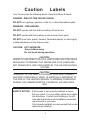
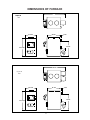
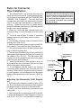
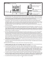
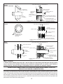
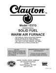
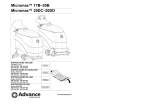
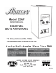
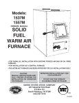
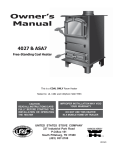
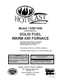
HOTBLAS T
Model 1300/1400
OWNERS MANUAL
SOLID FUEL
WARM AIR FURNACE
*FOR PARALLEL INSTALLATION WITH
EXISTING FORCED AIR-GAS OR OIL
FIRED FURNACE (U.S. ONLY)
*FOR INSTALLATION AS A CENTRAL FURNACE
*CERTIFIED UNDER ANSI/UL 391 & CAN/CSA-B366.1-M91
STATES STO
TED
V
NI
USSC
COMPANY
E
U
CAUTION:
READ ALL INSTRUCTIONS CAREFULLY BEFORE STARTING THE
INSTALLATION OR OPERATING
THE FURNACE
IMPROPER INSTALLATION MAY VOID
YOUR WARRANTY
DO NOT USE THIS FURNACE
IN A MOBILE HOME OR TRAILER
UNITED STATES STOVE COMPANY
227 Industrial Park Road
P.O.Box 151
South Pittsburg, TN 37380
(423) 837-2100
851486 02/01
CONGRATULATIONS!
You've purchased one of America's Finest Wood and Coal
Burning Furnaces. By heating with wood and coal you're
helping CONSERVE AMERICA'S ENERGY! Wood is our
Renewable Energy Resource. Please do your part to
preserve our wood supply. Plant at least one tree each year.
Future generations will thank you.
NOTE: YOUR UNIT MUST BE INSTALLED BY A
QUALIFIED FURNACE INSTALLER.
TOOLS AND MATERIALS NEEDED
MATERIAL
TOOLS
Pencil
6 Foot Folding Rule or Tape
Tin Snips
Drill, Hand or Electric
Drill Bit- 1/8" Dia.
(For Sheet Metal Screws)
Screw Driver (Blade-Type)
Gloves
Sabre Saw
5/16" Nut Driver or
5/16" Socket w/Ratchet
6" Pipe, 6" Elbow, Collar and Thimble;
as required (24 gauge min.)
1/2" Sheet Metal Screws
6" Inside diameter Listed Residential
Type or Building Heating Appliance
Chimney or existing masonry chimney
Electrical Wiring
6" Draft Regulator
1/2" Conduit (Conduit Connectors)
Furnace Cement (Manufacturer
Recommends: Rutland Black-Code 78
or Equivalent)
Plenum and Duct work as required.
2
Caution
Labels
Your Furnace has the following labels. Read and Obey all labels.
DANGER: RISK OF FIRE OR EXPLOSION.
DO NOT burn garbage, gasoline, drain oil, or other flammable liquids.
WARNING: FIRE HAZARD.
DO NOT operate with fire draft exceeding .06 inches w.c.
DO NOT operate with fuel loading or ash removal doors open.
DO NOT store fuels, paints, thinners, flammable liquids, or other highly
volatile substances in the furnace room.
CAUTION: HOT SURFACES
Keep children away.
Do not touch during operation.
_______________________CAUTION!________________________
INSPECT FLUE PIPES, FLUE PIPE JOINTS AND FLUE PIPE SEALS
REGULARLY TO ENSURE THAT SMOKE AND FLUE GASES ARE
NOT DRAWN INTO, AND CIRCULATED BY, THE AIR CIRCULATION
SYSTEM.
CAUTION!
CLEANOUT OF THE HEAT EXCHANGER, FLUE PIPE, CHIMNEY,
AND DRAFT INDUCER (IF USED), IS ESPECIALLY IMPORTANT AT
THE END OF THE HEATING SEASON TO MINIMIZE CORROSION
DURING THE SUMMER MONTHS, CAUSED BY ACCUMULATED
ASH.
SAFETY NOTICE: If this heater is not properly installed, a house
fire may result. For your safety, follow the installation directions. Contact local building or fire officials about restrictions and installation inspection
requirements in your area.
If not already installed, we recommend that smoke
detectors be installed.
3
Rules for safe installation and operation
Read these rules and the instructions carefully. Failure to follow them will cause a hazard that
could result in death, serious bodily injury, and/or property damage.
1. Check your local codes. The installation must comply with their rulings.
2. Do not install this furnace in a mobile home or trailer.
3. Always connect this furnace to a chimney and vent to the outside. Never vent to another room
or inside a building.
4. Do not connect this furnace to an aluminum Type B gas vent. This is not safe and is prohibited
by the National Fire Protection Association Code. This furnace requires a masonry or a UL/ULC
Listed Factory Built Chimney for residential type or Building Heating Appliance Chimney. Use a 6"
diameter chimney or larger, that is high enough to give a good draft. (See page 7)
5. Be sure that if a masonry chimney is used, it is safely constructed and in good repair. Have the
chimney inspected by the Fire Department or an inspector.
6. Inspect chimney connector and chimney before and frequently during the heating season for any
deposit of creosote or soot which must be removed (See Chimney Maintenance, page 18).
7. Provide air for combustion into the room where the furnace is located. If the intake is not in the
same room, air must have free access to the room.
8. CAST IRON PARTS MUST BE "SEASONED" TO AVOID CRACKING, BUILD ONLY SMALL
FIRES ON FIRST USE.
9. To prevent injury, do not allow anyone to use this furnace who is unfamiliar with the correct
operation of the furnace.
10. For further information on using your furnace safely, obtain a copy of the National Fire Protection
Association (NFPA) publication "Chimney's, Fireplaces and Solid Fuel Burning Appliances" NFPA
211. The address of the NFPA is Batterymarch Park, Quincy, MA 02269. For more information on
Canadian installation, obtain a copy of CAN/CSA-B365-M91 Installation Code for Solid-FuelBurning Appliances and Equipment.
11. Keep the ashpit section free of excess ashes. Do not allow ashes to stack higher than the sides
of the ash pan.
12. DISPOSAL OF ASHES- Place ashes in a metal container with a tight fitting lid. Keep the closed
container on a noncombustible floor or on the ground, well away from all combustible materials. Keep
the ashes in the closed container until all cinders have thoroughly cooled. The ashes may be buried
in the ground or picked up by a refuse collector.
13. CAUTION- The special paints used on your furnace may give off some smoke while they are
curing during first few fires., Build small fires at first. The metal used in construction of the furnace
and duct work has a light coating of oil. This could give off smoke and/or odor from registers when
furnace is used for the first time. This should disappear after a short period of time. Once this burnoff has occurred, it should not reoccur.
14. CARING FOR PAINTED PARTS- This furnace has a painted outside jacket, which is durable,
but it will not stand rough handling or abuse. When installing your furnace, use care in handling.
Clean with soap and warm water when furnace in not hot. DO NOT use any acids or scouring soap,
as these wear and dull the finish. DISCOLORATION WILL OCCUR IF THE FURNACE IS
OVERHEATED. FOLLOW OPERATING INSTRUCTIONS CAREFULLY.
15. Keep the feed and ash doors closed at all times except while tending the furnace.
Your Furnace is designed to be installed in a parallel air flow arrangement with a gas or oil-fired
forced air upflow-type central furnace, or it may be installed as a central furnace.
4
HOW THE FURNACE FUNCTIONS
PARALLEL INSTALLATION: (U.S. ONLY)
(See Optional Wiring Diagram, Page 16, Fig.
15) The design is such that when the blower
comes on, the blower on the central system
also comes on. The blower will only come on
when the temperature in the plenum has
reached the setting on the blower control.
This is to insure that there is sufficient warm air
in the system to make it efficient for the unit to
operate. When the central system thermostat
calls for heat, the central system will operate
by the burner igniting and the blower coming
on. It is possible that both systems will operate
simultaneously. It is recommended that for the
most efficient use of your HOTBLAST Furnace, that it be fired as much as possible in
order to reduce the demand on your existing
central heating system. This unit has an optional forced draft kit that operates from a wall
thermostat. When the temperature falls below
the setting on the wall thermostat, the forced
draft will come on (U.S. Stove Option 11/DKU)
The warm air supply outlet of the
HOTBLAST Furnace shall not be connected
to the cold air return of the central furnace,
because the possibility exists of components
of the central furnace overheating and causing the central furnace to operate other than is
intended.
SERIES INSTALLATION: (U.S. & CANADA)
This type of installation uses only the blowers
of the existing central furnace. The solid fuel
fan/limit control must also control the functions
of the existing furnace. All electrical power
must come from a single branch circuit (See
Fig. 15).
Your HOTBLAST Furnace is designed
to be a supplemental or central heating source
for your home. This Solid Fuel Furnace may
be installed in conjunction with a properly
operating central furnace that is listed or certified in accordance with nationally recognized safety standards and equipped with the
required controls and other safety features
and which has been installed in accordance
with appropriate standards of the National
Fire Protection Association with installation
clearances specified in the furnace nameplate marking. The installation must be accomplished by a qualified agency (one who is
engaged in, and is responsible for, or is thoroughly familiar with the installation and operation of the gas, oil, and solid fuel burning
heating appliances, who is experienced in
such work, familiar with all the requirements of
the authority having jurisdiction.) The installation shall be in strict accordance with the
manufacturer's installation instructions furnished with the solid fuel furnace.
The chimney connector of the furnace is
to be installed to provide clearances to combustible material not less than specified in the
individual classifications and marked on the
furnace. The chimney connector must be
connected to a chimney suitable for use with
residential type or building heating appliances
which burn solid fuel.
The Furnace is designed to operate in
either parallel or series air flow arrangement
with the central furnace or as a central furnace.
CENTRAL FURNACE INSTALLATION: As
a central furnace, the unit functions independently of any other system. The blower will
come on when the plenum temperature
reaches the setting on the blower control.
5
DIMENSIONS OF FURNACE
41"
Figure1A
1A
Figure
1300
1300
24-7/8"
21-1/32"
1-3/4"
33-7/8"
40-11/16"
9"
49-1/8"
Figure
Figure
1B1B
1400
1400/1500
32-1/8"
24-1/16"
1-3/4"
33-7/8"
40-11/16"
9"
6
Locating the Furnace
18"
1. The furnace should be located in the
same room as the central system
and as close as possible, but not
closer than 9". There should be no
wall between the furnace and the
warm air outlet duct that is connected
directly to the warm air outlet plenum
of the central furnace. (See Fig. 2)
12"
6" CHIMNEY
9"
CENTRAL
FURNACE
48"
2. The unit will require installation with
the following clearances:
Unit to sidewall............12"(305mm)
Unit to backwall...........30"(760mm)
Chimney connector pipe to sidewall
.....................................18"(460mm)
Chimney connector pipe to backwall
.....................................18"(460mm)
Hot air ducts to combustibles
.......................................6"(150mm)
(Refer to Fig. 2 & 3)
Figure 2
18"
6" SOLID DAMPER
6" BAROMETRIC
DRAFT REGULATOR
(OPTIONAL)
18"
3. Place the furnace on a noncombustible floor.
4. Check figures 2 and 3. Be sure you
have the clearances shown from the
furnace and the connector pipe to
combustible surfaces. If you have a
solid brick or stone wall behind your
furnace, you can place the furnace
as close as you wish to the wall. If the
wall is only faced with brick or stone,
treat it as a combustible wall.
NON-COMBUSTIBLE FLOOR
Figure 3
7
THIMBLE
6" ELBOW
6" SOLID DAMPER
6" BAROMETRIC
DRAFT REGULATOR
(OPTIONAL)
6" CHIMNEY
CONNECTOR
NON-COMBUSTIBLE
WALL
6" ELBOW
Chimney Connection
Fig. 4
MASONRY CHIMNEY
Before using an existing masonry chimney, clean the chimney and inspect the flue liner to be sure
it is safe to use. Make repairs before attaching the furnace. See page 4, item 5. Look at Fig. 4.
The connector pipe and fittings you will need to connect directly to a masonry chimney are shown.
The chimney connection should be as short as possible.
If the connector pipe must go through a combustible wall before entering the masonry chimney,
consult a qualified mason or chimney dealer. The installation must conform to local fire codes, and
N.F.P.A. 211.
DO NOT CONNECT THIS FURNACE TO A CHIMNEY FLUE SERVING ANOTHER APPLIANCE.
The chimney used for a furnace must not be used to ventilate the cellar or basement. If there is
a cleanout opening at the base of the chimney, close it tightly.
2' MIN.
10'
3' MIN.
REFER TO CHIMNEY
MANUFACTURER'S
INSTRUCTIONS AND
PARTS.
Fig. 5
6" SOLID DAMPER
6" BAROMETRIC
DRAFT REGULATOR
(OPTIONAL)
6" CHIMNEY CONNECTOR
6" ELBOW
LISTED FACTORY BUILT CHIMNEY
Carefully follow chimney manufacturer's instructions. Use only a Listed Residential Type or
Building Heating Appliance Chimney. If your chimney starts at the ceiling (Fig. 5), you will need
enough 6" pipe to reach the ceiling.
The top of the chimney must be at least 3 feet above the roof and be at least 2 feet higher than any
point of the roof within 10 feet (Fig. 5).
8
Rules for Connector
Pipe Installation
1. The crimped end of the chimney connector fits
inside the furnace flue collar. Install additional chimney connectors and elbow with the CRIMPED END
TOWARD THE FURNACE. This will allow any
condensation in the flue to run back into the furnace.
Use 6" dia. steel pipe and elbows for connection to
chimney. Never use less than 26 gauge and although blued steel is satisfactory, high temp painted
black is much more desirable.
2. Slope any horizontal pipe upward toward the
chimney at least 1/4 inch for each foot of horizontal
run.
3. You must have at least 18 inches of clearance
between any horizontal piping and the ceiling.
(See Fig. 3)
4. The chimney connector must not extend into the
chimney flue. (See Fig. 6)
5. Seal each chimney connector pipe joint with furnace cement. Also seal the pipe at the chimney.
6. Use 3 sheet metal screws at each chimney pipe
joint to make the piping rigid.
7. The chimney connector may include a section for
a barometric draft regulator between the furnace and
the chimney (Fig. 4,5, &7). The barometric draft
regulator must be installed in the same room (same
pressure zone) as the furnace.
8. Install the barometric draft regulator strictly in
accordance with the instructions that are provided
with the barometric draft regulator.
9. A solid damper must be used in the chimney
connecting pipes between the flue collar and the
chimney. When used in conjunction with a barometric draft regulator, the solid damper must be placed
between the barometric and the chimney. (See Fig.
4,5,7)
Adjusting the Barometric Draft Regulator
1. Drill a hole in the chimney connector within 18" of
the flue collar below the barometric draft regulator
just large enough for the tube of the manometer.
2. Build a fire after all chimney connections have
been made.
3. Use a manometer to measure the draft in the flue.
4. Adjust the Barometric Draft Regulator to obtain a
draft of 0.05 - 0.06" W.C. under stable fire conditions.
9
NOTE:
A flue pipe shall not pass through an attic,
roof space, closet or similar concealed space,
a floor or ceiling of combustible construction. Where passage through a wall or partition is desired, installation must conform
with UL standards.
RIGHT
WRONG
WRONG
Fig. 6
NON-COMBUSTIBLE
INSTALLATION PER
NFPA 211
6" SOLID DAMPER
6" BAROMETRIC
DRAFT REGULATOR
(OPTIONAL)
MEASURE FLUE
DRAFT HERE
Fig. 7
CONNECTION OF CHIMNEY CONNECTOR TO A MASONRY CHIMNEY THROUGH A COMBUSTIBLE WALL
Figure 8 shows how to connect the chimney connector of a heater to a masonry chimney through a combustible wall.
There are five allowable ways that a chimney connector can be connected to a masonry chimney by passing through
a combustible wall. NFPA Standard 211 allows the following wall pass-through systems.
CHIMNEY FLUE
FIGURE 8 CONNECTION OF CHIMNEY CONNECTOR TO A MASONRY CHIMNEY THROUGH A COMBUSTIBLE WALL
CEILING
SEE PARTS A, B,
C, D, AND E OF
THIS FIGURE FOR
OPTIONS.
CHIMNEY CONNECTOR
MASONRY CHIMNEY
CONSTRUCTED TO
NFPA 211
TO
HEATER
COMBUSTIBLE WALL
FLOOR
PROTECTOR
AIRTIGHT
CLEANOUT
DOOR
(FIGURE 8 CONTINUED ON NEXT PAGE)
10
MINIMUM CHIMNEY CLEARANCE TO
BRICK AND COMBUSTIBLES IS 2 IN.
MINIMUM 12 IN.
TO COMBUSTIBLES
CHIMNEY FLUE
PART A, FIGURE 8
(FIGURE 8 CONTINUED ON NEXT PAGE)
MINIMUM CLEARANCES 12 IN.
OF BRICK ALL AROUND
MASONRY CHIMNEY
CONSTRUCTED TO
NFPA 211
CHIMNEY CONNECTOR
TO HEATER
FIRE CLAY LINER
(5/8" MIN. WALL THICKNESS)
MIN. 3-1/2" THICK BRICK
MASONRY WALL
1. Use a minimum 3-1/2" thick brick masonry wall framed into the combustible wall. A fireclay liner (ASTM C315 or
equivalent) having a 5/8" minimum wall thickness must be used and it must be at least 12" away from any material
that could catch fire. The inside diameter of the fireclay liner shall be sized for the proper snug fit of a 6" diameter
chimney connector pipe. The fireclay liner shall run from the outer surface of the brick wall to, but not beyond, the
inner surface of the chimney flue and shall be firmly cemented in place. See Part A of Figure 8.
2. Use a solid insulated listed factory-built chimney length having an inside diameter of 6" and having 1" or more of
solid insulation. There must be at least a 9" air space between the outer wall of the chimney length and any
combustible materials. The inner end of the chimney length shall be flush with the inside of the masonry chimney
flue shall be sealed to the flue and to the brick masonry penetration with nonwater-soluble refractory cement. Sheet
steel supports which are at least 24 gauge(0.024") in thickness shall be securely fastened to wall
surfaces on all sides. Fasteners between supports and the chimney length shall not penetrate the chimney liner.
See Part B of Figure 8.
3. Use a 10" diameter ventilated thimble made of at least 24 gauge(0.024") steel having two 1" air channels. The ventilated thimble must be separated from combustible materials by a minimum of 6" glass fiber insulation. The opening
in the combustible wall shall be covered and the thimble supported with sheet steel supports which are at least 24
gauge (0.024") in thickness. The sheet steel supports shall be securely fastened to wall surfaces on all sides and
shall be sized to fit and hold the chimney section. Fasteners used to secure chimney sections shall not penetrate
chimney flue liner. See Part C of Figure 8.
4. Use an 8" inside diameter solid insulated listed factory-built chimney length which has 1" or more of solid insulation.
The minimum length of this chimney section shall be 12" and will serve as a pass-through for the 6" diameter
chimney connector. There must be at least a 12" air space between the outer wall of the chimney section and any
combustible materials. The chimney section shall be concentric with and spaced 1" away from the chimney connec
tor by means of sheet steel support plates on both ends of the chimney section. The opening in the combustible wall
shall be covered and the chimney section supported on both sides with sheet steel supports which are at least 24
gauge (0.024") in thickness. The sheet steel supports shall be securely fastened to wall surfaces on all sides and
shall be sized to fit and hold the chimney section. Fasteners used to secure chimney sections shall not penetrate
chimney flue liner. See Part C of Figure 8.
5. A listed factory-built wall pass-through system may be purchased and installed according to the instructions pack
aged with it to provide a safe method of passing the chimney connector through a combustible wall for connection
to a masonry chimney.
Additional requirements pertaining to Figure 8 and the above wall pass-through systems:
1. Insulation material used as part of wall pass-through system shall be of noncombustible material and shall have a
thermal conductivity of 1.0 Btu • in./ft.² • °F (4.88 kg • cal/hr • m² • °C) or less
2. All clearances and thicknesses are minimums: larger clearances and thickness are acceptable.
3. A chimney thimble, as shown for 3" and 4" above (Parts C and D respectively of Figure 8) shall be for types "3" and
4" connections to facilitate removal of the chimney connector for cleaning. The chimney thimble shall be of ASTM
C315 fireclay with 5/8" minimum wall thickness , or material or equivalent durability. The inside diameter of the
thimble shall be sized for the proper snug fit of a 6" diameter chimney connector pipe. The thimble shall be installed
without damage to the chimney flue. The thimble shall extend through the chimney wall to, but not beyond, the
inner surface of the chimney flue and shall be permanently cemented in place with high temperature cement.
4. A chimney connector to a masonry chimney, except for 2" above (Part B of Figure 8), shall extend through the wall
pass-through system to the inner face of the chimney flue, but not beyond. It does not have to be fastened in place
so long as it cannot accidently be pulled out of the chimney or shoved into the chimney flue. If fasteners are used
to secure the chimney connector to a masonry chimney, the fasteners shall not penetrate the chimney flue liner.
5. Any material used to close up any opening for the connector shall be noncombustible.
11
PART B
FIGURE 8 (FIGURE 8 CONTINUED)
NONSOLUBLE
REFACTORY
CEMENT
AIR SPACE
FACTORY-BUILT
CHIMNEY LENGTH
CHIMNEY FLUE
MINIMUM CHIMNEY CLEARANCES FROM MASONRY TO
SHEET STEEL SUPPORTS AND COMBUSTIBLES 2 IN.
CHIMNEY LENGTH
FLUSH WITH INSIDE
OF FLUE
AIR SPACE
9 IN. MINIMUM
MINIMUM CLEARANCE
9 IN. ALL AROUND
CHIMNEY CONNECTOR
TO HEATER
USE CHIMNEY MFRS. PARTS TO
ATTACH CONNECTOR SECURELY
SOLID INSULATED, LISTED
FACTORY-BUILT CHIMNEY LENGTH
MASONRY CHIMNEY CONSTRUCTED
TO NFPA 211
PART C
FIGURE 8
SHEET STEEL SUPPORTS
(24 GAUGE MIN. THICKNESS)
MINIMUM CHIMNEY CLEARANCES FROM MASONRY TO
SHEET STEEL SUPPORTS AND COMBUSTIBLES 2 IN.
24 GAUGE
VENTILATED THIMBLE WITH
TWO 1 INCH AIR CHANNELS
CHIMNEY FLUE
CHIMNEY THIMBLE
TWO VENTILATED AIR
CHANNELS EACH 1 INCH.
CONSTRUCTED OF
SHEET STEEL.
MASONRY CHIMNEY CONSTRUCTED
TO NFPA 211
CHIMNEY CONNECTOR
TO HEATER
MINIMUM 6 IN. GLASS
FIBER INSULATION ALL AROUND
SHEET STEEL SUPPORTS
(24 GAUGE MIN. THICKNESS)
MINIMUM CHIMNEY CLEARANCES FROM MASONRY TO
SHEET STEEL SUPPORTS AND COMBUSTIBLES 2 IN.
PART D
FIGURE 8
SHEET STEEL SUPPORTS
MINIMUM CLEARANCE
2 IN. ALL AROUND
CHIMNEY SECTION
1 IN. AIR SPACE TO
CHIMNEY LENGTH
CHIMNEY THIMBLE
CHIMNEY FLUE
CHIMNEY
CONNECTOR
AIR SPACE
2 IN.
MASONRY CHIMNEY CONSTRUCTED
TO NFPA 211
CHIMNEY CONNECTOR
TO HEATER
SOLID INSULATED, LISTED
FACTORY-BUILT CHIMNEY
LENGTH (12 IN. LONG MIN.)
SHEET STEEL SUPPORTS
(24 GAUGE MIN. THICKNESS)
PART E - (Figure 8)
In addition to the methods shown by A, B, C, and D of Figure 8, a listed factory-built wall pass-through system
may be purchased and installed according to the instructions packaged with it to provide a safe method of
passing chimney connector through a combustible wall for a connection to a masonry chimney.
CONNECTION OF CHIMNEY CONNECTOR TO A MASONRY CHIMNEY WHEN CHIMNEY CONNECTOR
DOES NOT PASS THROUGH A COMBUSTIBLE WALL
If the chimney connector does not have to pass through a combustible wall to get to a masonry chimney, simply connect
the chimney connector directly to the masonry chimney's chimney thimble as described and shown by parts C and D of
Figure 8. Remember, the chimney connector should extend into the chimney thimble to the innerface of the chimney flue
but not beyond; if the chimney connector is extended through the chimney thimble into the chimney flue, resistance to the
flow of smoke and gases up the chimney will occur; that flow resistance will have an adverse affect on the operation and
performance of the heater and venting system.
12
Assembly of Furnace
Your furnace requires the following items
to be assembled or installed by the service
person:
Feed Door Pull Handle
Feed Door Locking Handle
Blower(s) and Blower Controls
Electrical Connections
1.
2.
3.
4.
5.
6.
7.
8.
Remove all parts from inside the furnace
and inspect for damage, including the
firebrick as some breakage could occur
during shipment.
Assemble the feed door pull handle as
shown in Figure 9. Install thermostat
assembly and cover (complete with
handle) as illustrated in Figure 9.
Align thermostat control knob with flat on
thermostat control shaft and press onto
shaft. (See Fig. 9)
Attach feed door locking handle as in
Figure 10 with screws and nuts provided.
Note: Slotted holes are for adjustment of
handle. Adjust handle until some pressure is required to lock feed door during
firing sequence.
Install Honeywell Fan/Limit Control on
rear of furnace cabinet as shown in Figure 11.
Remove blower(s) from carton(s). Remove junction box cover. Attach clip nuts
as in Figure 10. Install blower(s) and
gasket(s) with 1/4"-20x3/4" bolts as
shown.
Wire right side blower first (See wiring
diagram, Fig. 12 & 13) and replace cover
on junction box on blower.
Wire left blower same as above and
replace cover.
Check operation of shaker grates with
grate handle before operating furnace.
Fig. 9
Fig. 10
Honeywell
FAN/LIMIT
CONTROL
4" ELECTRICAL
JUNCTION BOX
BLOWER
ASSEMBLY
GASKET
CLIP NUTS
(DO NOT USE CLIP NUT
ON UPPER CENTER HOLE)
(MODEL 1300 - 1 BLOWER,
MODEL 1400 - 2 BLOWERS)
Fig. 11
13
LOAD
LIMIT
BREAK OFF
JUMPER FOR LINE
LOW VOLTAGE
LOAD
FAN
LINE
FAN "OFF"
INDICATOR
LIMIT
INDICATOR
FAN "ON"
INDICATOR
Honeywell
LIMIT SWITCH
R2
R1
WIRE COLOR CODE
G- GREENWIREGROUND
COLOR CODE
BSUPPLY
G BLACK- GREENPOWER
- GROUND
WSUPPLY
B -WHITEBLACK POWER
- POWER
SUPPLY
R1CONTROL
W -WHITEWHITE FAN
- POWER
SUPPLY
R1 BLACK- WHITE FAN
- FAN
CONTROL
R2CONTROL
R2 -BLACKBLACK BLOWER
- FAN CONTROL
M1MOTOR
M1 WHITE- BLACKBLOWER
- BLOWER
MOTOR
M2MOTOR
M2 - BLACK - BLOWER MOTOR
WIRE NUTS
GROUND
G
G
B
B
110
VAC,
60
HZ.
W
W
M2
ELECTRICAL JUNCTION BOX
M1
Fig. 12
BLOWER
MOTOR
Fig. 11
IMPORTANT: POWER SUPPLY WIRING MUST NOT BE LESS THAN 90 CENTIGRADE.
LOAD
FAN
LINE
LOAD
LIMIT
BREAK OFF
JUMPER FOR LINE
LOW VOLTAGE
FAN "OFF"
INDICATOR
LIMIT
INDICATOR
FAN "ON"
INDICATOR
Honeywell
LIMIT SWITCH
R2
WIRE COLOR CODE
WIRE COLOR
CODE
G- GREENGROUND
G - BGREEN
- GROUND
BLACKPOWER SUPPLY
B - WBLACK
- POWER
SUPPLY
WHITEPOWER
SUPPLY
W -R1WHITE
- POWER
SUPPLY
WHITEFAN CONTROL
R1 R2- WHITE
FAN
CONTROL
BLACK- FAN CONTROL
R2 M1- BLACK
- FAN
CONTROL
BLACKBLOWER
MOTOR
M1 - BLACK - BLOWER MOTOR
M2- WHITE- BLOWER MOTOR
M2 - BLACK - BLOWER MOTOR
R1
GROUND
G
110 G
VAC,
B
60
HZ. W
B
W
M2
ELECTRICAL JUNCTION BOX
M1
BLOWER
MOTOR
BLOWER
MOTOR
M1
M2
WIRE NUT
(7 PLACES)
Fig.
Fig.
1312
IMPORTANT: POWER SUPPLY WIRING MUST NOT BE LESS THAN 90 CENTIGRADE.
14
Installation
Pipe to combustible:
Sides: 18"(460mm)
Back: 18"(460mm)
The installation must be made only on a noncombustible floor.
d) Install the smoke pipe connector to the chimney with 26-gauge pipe and elbows (to be purchased separately), maintaining the proper clearances for the specific model. Seal the smoke pipe
in the chimney with furnace cement. (The chimney
connector shall be securely supported, and joints
fastened with sheet metal screws or rivets.)
e) Install 8" diameter heat pipe to plenum of the
central hot air furnace. Use 26-gauge pipe and
connectors (to be purchased separately). (See Fig.
14) If central air conditioning is installed in the
plenum, install heat pipe above the air conditioning
unit. Secure heat pipe connection with supports
and sheet metal screws.
f) Connect electrical supply in the electrical junction box that is mounted on the back of the Furnace.
See Wiring Diagram (Fig. 12 or Fig. 13). Remove
the cover from electrical junction box and connect
power supply wires to wires designated, using wire
nuts. The power cord supplied may be used for
installation, if permitted by local codes and
regulations. If the power cord supplied cannot be
used, the power supply wiring must be 90 degrees
centigrade in a metal cable and should be completed
by a qualified installer complying with NFPA Standard
No. 70 and local codes.
g) Optional Plenum Fan Control Switch (Part No.
11PCS) is available for installation on the plenum of
central hot air heating furnace. The purpose of this
switch is to activate the circulating fan of the central
hot air heating furnace when the temperature in the
plenum exceeds 120 degrees F., and shut off the
fan when the temperature in the plenum is reduced
to 100 degrees F. This avoids overheating the
plenum.
The electrical supply for operation of this fan
control switch is to be obtained from the same
electrical supply as the central hot air heating system. Follow the instructions of the wiring diagram
(Fig. 12 or 13) Do not make connections across
Limit Control in the furnace.
Make electrical wire connections in accordance
with NFPA Standard No. 70 and local codes in the
power supply junction box (See Fig. 15). The wiring
to complete the connections should be 18 AWG
minimum copper and 90 degrees centigrade in a
cable.
Please see all methods of Installation in
Appendix at the rear of this booklet.
This is a furnace, not a free standing stove.
You must direct heated air from 8" outlets away from
the furnace, or it will not function properly.
1. This installation must be done by a qualified
heating equipment installer.
2. The installation is to be done in compliance with
National Fire Protection Association installation standards: No. 89M, 90B, 211, 70 (National Electrical
Code) and Uniform Mechanical Code 913, 6-4, in the
states where applicable. (Their code offers connecting smoke pipe connectors into chimney with
other fuel burning appliances.)
3. Rooms large in comparison with size of the
appliance:
a)Wood or Coal Burning Furnace needs air for
combustion and circulation to house.
b) Provision must be made to make up this air
and not starve gas or oil furnace of combustion air.
c) Have "Authority Having Jurisdiction" determine that air is of adequate makeup. (Reference
N.F.P.A. Nos. 30&54, Code for Installation of Gas &
Oil Equipment).
4. Have "Authority Having Jurisdiction" is to inspect
all chimneys and installations for adequate venting
and for compliance with standard and local codes
and regulations regarding installation of wood burning appliances.
5. Installation for Supplemental Heat Application to
Existing Central System. (See Fig. 2 for typical
installation.)
a) Place Wood or Coal Burning Furnace so that
the chimney connector will be as short as practical
and avoiding unnecessary sharp turns in the smoke
pipe connector and the installation of devices that
would create excessive resistance to the flow of flue
gases.
b) Locate the Wood or Coal Burning Furnace as
close as practical to the existing central hot air
heating system, maintaining clearances as stated
on the label on the fuel door.
c) Clearance from combustible materials must
comply with those stated on the label on the fire
door:
Unit to combustible:
Front: 48"(900mm)
Back: 30"(760mm)
Sides: 12"(305mm)
Plenum to Ceiling: 6"(150m)
15
Figure 14
PLENUM
6" MIN.
MIN.
TO 18"
CEILING
2" MIN. AIR SPACE
REQUIRED BY CODE
CENTRAL
FURNACE
TO GAS/OIL/ELECTRIC
TRANSFORMER AND
COMBUSTION FAN OF
SOLID FUEL UNIT
Figure 15
COMBINATION CONTROL
LIMIT
H
POWER
SUPPLY
JUMPER IN
N
FAN
GAS/OIL/ELECTRIC
POWER SUPPLY
JUNCTION BOX
CAUTION!
DO NOT CONNECT
PLENUM FAN CONTROL
SWITCH ACROSS FURNACE
LIMIT CONTROL.
FURNACE
BLOWER
MOTOR
Power Failure Instructions:
Operation after loss of power-1. Remove filter if provided
2. Do not expect to keep home at normal temperatures.
3. Do not load fuel above bottom of feed door.
16
CAUTION
GASES THAT ARE DRIVEN FROM FRESH
COAL MUST BE BURNED OR THEY WILL
ACCUMULATE AND EXPLODE. NEVER
SMOTHER A FIRE WHEN ADDING FRESH
COAL.
Operating Instructions
FUEL, Model 1300
Egg size (1-3/16" or larger) bituminous coal
for residential furnaces, or any of the specially
packed fireplace coals can be used. Coal with a
low ash content (2% to 6%) is recommended.
FUEL, Model 1400
Hardwood, 18" to 26" should be split and air dried
(seasoned) for 6 months.
LIGHTING
1. Set the thermostat on "HIGH" for maximum
draft.
2. Open the feed door and place paper and
kindling on the grate for starting the fire.
3. Light the fire and close the feed door.
4. Add wood or about 15 lbs. of coal (depending
on which model) after fire is burning briskly.
Set thermostat for desired temperature.
5. "MEDIUM" setting is normally satisfactory.
Set higher or lower for your comfort.
ADDING FUEL
When starting a fire, add small amounts of fuel
instead of adding large quantities of fuel. This will
give more complete combustion and less buildup
of tars or soot in the chimney.
1. Set thermostat to HIGH before opening feed
door.
2. Wood fire - Model 1400.
Add wood to a convenient level.
3. Coal Fire - Model 1300.
a. Never smother the fire when adding coal (See
Caution). Gas accumulation and a mild smoky
explosion will occur. Add fresh kindling if the
bed of coals has cooled.
b. Add up to 20 lbs. of coal per loading. Never add
coal above the bottom of feed door opening.
Stir the coal and watch the fire. Be sure the
c. new coal is burning briskly before you close
the doors and turn the thermostat down.
Shake grates vigorously 1/2" left to right to spill
d. ashes into the ash pan. Do this at least once
every 12 hours of operation. Empty ash pan
regularly. Do not allow ashes to buildup to
grate as grate will warp and burnout, and you
might spill the ashes when removing the pan.
Dispose of hot ashes properly (See note 12 on
page 4).
Rotation of the handle (5 o'clock to 7 o'clock)
e. position will agitate coals and spill ashes into
ash pan.
It is advisable for you to get familiar with the
f. shaker grate operation before firing.
CAUTION
DO NOT OPERATE WITH THE FEED AND/OR
ASH DOOR OPEN. THIS FURNACE IS DESIGNED FOR THERMOSTATIC OPERATION.
OPERATION WITH ANY OF THESE DOORS
OPEN WILL OVERHEAT AND DAMAGE THE
FURNACE.
CAUTION
NEVER USE GASOLINE, GASOLINE-TYPE
LANTERN FUEL, KEROSENE, CHARCOAL
LIGHTER FLUID, OR FLAMMABLE LIQUIDS
TO START OR "FRESHEN UP" A FIRE IN THE
FURNACE.
WARNING
NEVER STORE FLAMMABLE LIQUIDS, ESPECIALLY GASOLINE, IN THE VICINITY OF
THE FURNACE.
ADJUSTING BLOWER LIMIT CONTROL SETTINGS.
The temperature in the plenum of the warm air
furnace at which the blower turns on or turns off,
is controlled by the setting of the pointers in the
blower limit control. These pointers may be adjusted through their entire range of settings to
achieve the desired warm air output from furnace.
(See Fig. 16 below)
Move both pointers towards the right (counter
clockwise) - this increases the temperature
setting at which the blower will turn on and off.
Move both pointers towards the left (clockwise) - this decreases the temperature setting
at which the blower will turn on and off.
Move pointers away or apart from each otherthis increases the time that the blower will run
on each warm air cycle.
Fig. 16
BLOWER FAN
"OFF" POINTER
BLOWER FAN
"ON" POINTER
BLOWER LIMIT
POINTER & STOP
17
Service Hints
Do not expect a furnace to draw. It is the
chimney that creates the draft. Smoke spillage
into the house or excessive buildup of water or
creosote in the chimney are warnings that the
chimney is not functioning properly. Correct the
problem before using furnace. Possible causes
are:
4. If the chimney is operating too cool, water
will condense in the chimney and run back
into the furnace. Creosote formation will be
rapid and may block the chimney. Operate
the furnace at a high enough fire to keep the
chimney warm, preventing this condensation.
1. The connector pipe may be pushed into the
chimney too far, stopping the draft (Fig. 6)
5. If the fire burns well, but sometimes smokes
or burns slowly, it may be caused by the
chimney top being lower than another part
of the house or a nearby tree. The wind
blowing over a house or a tree, falls on top
of the chimney like water over a dam, beating down the smoke. The top of the chimney
should be at least 3 feet above the roof and
be at least 2 feet higher than any point of the
roof within 10 feet (Fig. 5).
2. Do not connect two furnaces or a stove and
furnace into the same chimney flue.
3. The chimney used for a furnace must not be
used to ventilate the cellar or basement. If
there is a cleanout opening at the base of
the chimney, it must be closed tightly.
6. See page 29 for list of trouble shooting tips.
A draft reading of .05 to .06 w.c. is suggested for proper burning of this unit when using
wood or bituminous coal as fuel. When using anthracite coal, this draft reading is a
minimum reading.
Chimney Maintenance
Creosote and Soot - Formation and Need for Removal
If creosote or soot has accumulated, it should
be removed to reduce the risk of a chimney fire.
When wood is burned slowly, it produces tar
and other organic vapors, which combine with
expelled moisture to form creosote. The creosote vapors condense in the relatively cool
chimney flue of a slow-burning fire. As a result,
creosote residue accumulates on the flue lining. When ignited, this creosote makes an
extremely hot fire.
Chimney fires burn very hot. If the chimney
catches fire, immediately call the fire department, then reduce the fire by closing the inlet air
control. Pour a large quantity of coarse salt,
baking soda or cool ashes on top of the fire in
the firebox.
When coal is burned, the products of combustion combine with moisture to form a soot residue which accumulates on the flue lining. When
ignited, this soot makes an extremely hot fire.
CAUTION
A chimney fire may cause ignition of
wall studs or rafters which you thought
were a safe distance from the chimney.
If you have a chimney fire, have your
chimney inspected by a qualified person before using again.
The chimney should be inspected at least twice
monthly during the heating season to determine if a creosote or soot build up has occurred.
18
12
Model 1300
Repair Parts
25
14
34
14c
24
6
3
2
14b
1
13
33
5
4
16
14a
15
22
31
8
23
28
37
9
7
36
20
38
30
10
21
29
18
30
19
27
26
32
11
35
17
19
PARTS LIST
MODEL 1300
(SEE DIAGRAM, PAGE 19)
KEY
1
2
3
4
5
6
N/S
N/S
7
8
9
10
N/S
N/S
11
12
13
14
14a
14b
14c
15
16
N/S
17
18
19
20
21
22
23
N/S
N/S
N/S
N/S
N/S
N/S
N/S
N/S
24
25
N/S
26
27
28
29
30
31
32
33
34
35
36
37
38
PART #
22684
22682
22762
88032
40246
22761
83227
83250
22683
22685
22662
23800
83337
83338
68218
68217
68733
68598
89175
86318
68721
89520
23425
83106S
89354
83045A
23445
83274
68238
22686
89308
83339
80230
83339
83340
89319
68231
68232
80154
80145
80231
80232
23397
40257
40256
40260
40264
68225
89066
68234
22140
22824
23787
83250
83445
DESCRIPTION
CABINET LEFT SIDE
CABINET BACK PANEL
FORCED DRAFT RING
FLUE COLLAR GASKET
FLUE COLLAR
FLUE COLLAR RING
BOLT (1/4-20 X 1)
KEP NUT (1/4-20)
CABINET TOP PANEL
CABINET RIGHT SIDE
FEED DOOR HINGE BRACKET
SMOKE CURTAIN
BOLT (5/16-18 X 1)
LOCKNUT (5/16-18)
ASH DOOR ASSEMBLY
FEED DOOR ASSEMBLY
THERMOSTAT COVER ASSEMBLY
THERMOSTAT ASSEMBLY
THERMOSTAT CONTROL KNOB
THERMOSTAT DAMPER CHAIN
THERMOSTAT DAMPER FLAP ASSEMBLY
WOODEN HANDLE
HANDLE BRACKET
SCREW (#10-24 X 1/2")
ASH DOOR HANDLE
WASHER (3/32 THK)
DOOR LATCH
NUT (3/8-16)
ASH PAN
CABINET BOTTOM
FEED DOOR LOCKING MECHANISM
BOLT (1/4-20 X 3/4")
BLOWER MOTOR
BOLT (1/4-20 X 3/4")
BLOWER CLIP NUT (1/4-20)
BLOWER GASKET
FAN CONTROL CORD ASSEMBLY
BLOWER CONDUIT ASSEMBLY
CORD STRAIN RELIEF
BLOWER LIMIT CONTROL
JUNCTION BOX
POWER SUPPLY CORD
FLUE BAFFLE
SHAKER GRATE
SHAKER FRAME
SHAKER HANDLE
FRONT AND REAR LINER
FIREBOX ASSEMBLY
FIREBRICK
BLOWER THERMOSTAT BRACKET
RELAY BOX SUPPORT BRACKET
DRAFT KNOB
SMOKE DOOR CLIP
KEP NUT (1/4-20)
BOLT (1/4-20 X 1-1/4")
20
QTY.
1
1
1
1
1
1
6
6
1
1
1
1
2
2
1
1
1
1
1
1
1
1
2
2
1
1
1
1
1
1
1
2
1
5
5
1
1
1
1
1
1
1
1
1
1
1
1
1
10
1
1
1
2
2
2
12
25
33
24
6
14
3
2
14c
1
14b
32
13
5
4
16
14a
15
22
29
8
23
37
9
7
Model 1400
Repair Parts
35
21
10
36
20
18
19
28
11
34
17
26
27
30
31
21
PARTS LIST
MODEL 1400
(SEE DIAGRAM, PAGE 21)
KEY
1
2
3
4
5
6
N/S
N/S
7
8
9
10
11
12
13
14
14a
14b
14c
15
16
N/S
17
18
19
20
21
22
23
N/S
24
25
N/S
N/S
26
27
28
29
30
31
32
33
34
N/S
N/S
N/S
N/S
N/S
35
36
37
PART #
23461
23459
22762
88032
40246
22761
83227
83250
23457
23461
22662
23800
68218
68217
68733
68598
89175
86318
68721
89520
23425
83106S
89354
83045A
23445
83274
68228
23458
89308
83339
80145
80231
80232
68231
23398
40263
40258
68215
23887
89066
68234
22140
22824
68229
83339
83340
89319
80154
23787
83445
83250
DESCRIPTION
CABINET LEFT SIDE
CABINET BACK PANEL
FORCED DRAFT RING
FLUE COLLAR GASKET
FLUE COLLAR
FLUE COLLAR RING
BOLT (1/4-20 X 1)
KEP NUT (1/4-20)
CABINET TOP PANEL
CABINET RIGHT SIDE
FEED DOOR HINGE BRACKET
SMOKE CURTAIN
ASH DOOR ASSEMBLY
FEED DOOR ASSEMBLY
THERMOSTAT COVER/PANEL ASSEMBLY
THERMOSTAT ASSEMBLY
THERMOSTAT CONTROL KNOB
THERMOSTAT DAMPER CHAIN
THERMOSTAT DAMPER FLAP ASSEMBLY
WOODEN HANDLE
HANDLE BRACKET
SCREW (#10-24 X 1/2")]
ASH DOOR HANDLE
DOOR LATCH WASHER (3/32 THK)
DOOR LATCH
DOOR LATCH NUT (3/8"-16)
ASH PAN
CABINET BOTTOM
FEED DOOR LOCKING MECHANISM
BOLT (1/4-20 X 3/4")
BLOWER LIMIT CONTROL
JUNCTION BOX
POWER SUPPLY CORD
FAN CONTROL CORD ASSEMBLY
FLUE BAFFLE
FURNACE GRATE
FRONT LINER
FIREBOX ASSEMBLY
HALF FIREBRICK
FIREBRICK
BLOWER THERMOSTAT BRACKET
RELAY BOX SUPPORT BRACKET
DRAFT CONTROL KNOB
BLOWER MOTOR ASSEMBLY
MOUNTING BOLT (1/4-20 X 3/4")
CLIP NUT (1/4-20)
BLOWER GASKET
CORD STRAIN RELIEF
SMOKE CURTAIN CLIP
BOLT (1/4-20 X 1-1/4")
KEP NUT (1/4-20)
22
QTY.
1
1
1
1
1
1
6
6
1
1
1
1
1
1
1
1
1
1
1
1
2
2
1
1
1
1
1
1
1
2
1
1
1
3
2
3
1
1
2
12
1
1
1
2
10
10
2
1
2
2
2
Central Installation
(U.S. ONLY)
COLD AIR DUCT
6" PIPE
90 ELBOW
DAMPER
OPTIONAL
11 RPT
PIPE
CONNECTOR
FURNACE
Fig.
17-1
Fig.
16-1
Add-On Installation
(U.S. ONLY)
COLD AIR DUCT
8" PIPE
6" PIPE
90 ELBOW
DAMPER
PIPE
CONNECTOR
FURNACE
EXISTING GAS/OIL/ELECTRIC FURNACE
Fig. 17
Fig. 16
23
APPENDIX
INSTALLATION A
(U.S. ONLY)
TO EXISTING
DUCT WORK
COLD AIR
RETURN
WARM AIR
EXISTING
FURNACE
FILTER BOX
SOLID FUEL
FURNACE
24
INSTALLATION B
(U.S. ONLY)
PLENUM
COLLECTOR BOX
TO EXISTING
DUCT WORK
COLD AIR
RETURN
WARM AIR
EXISTING
FURNACE
FILTER BOX
SOLID FUEL
FURNACE
INSTALLATION C
(U.S. ONLY)
PLENUM ELBOW
TO EXISTING
DUCT WORK
COLD AIR
RETURN
WARM AIR
PLENUM TOP
(OPTIONAL)
EXISTING
FURNACE
FILTER BOX
SOLID FUEL
FURNACE
25
INSTALLATION D
(U.S. ONLY)
DUCT
WORK
2" MINIMUM
CLEARANCE
11 PCS
(OPTIONAL PLENUM
FAN CONTROL LOCATION)
COLD AIR
RETURN
FURNACE PLENUM
ANTI-BACKDRAFT
FLAPPER
EXISTING FURNACE
SOLID FUEL
FURNACE
INSTALLATION E
(U.S. ONLY)
DUCT
WORK
2" MINIMUM
CLEARANCE
BAFFLE
COLD AIR
RETURN
FURNACE PLENUM
EXISTING FURNACE
SOLID FUEL
FURNACE
26
INSTALLATION F
DUCT
WORK
2" MINIMUM
CLEARANCE
COLD AIR
RETURN
FURNACE PLENUM
EXISTING FURNACE
SOLID FUEL
FURNACE
INSTALLATION G
DUCT
WORK
2" MINIMUM
CLEARANCE
CENTRAL
FURNACE
INSTALLATION
COLD AIR
RETURN TO
FILTER BOX
SOLID FUEL
FURNACE
27
INSTALLATION H
EXISTING OIL,
ELECTRIC OR
GAS FURNACE
SOLID FUEL
FURNACE
(TOP VIEW)
2" MINIMUM
CLEARANCE
EXISTING OIL,
ELECTRIC OR
GAS FURNACE
SOLID FUEL
FURNACE
(FRONT VIEW)
26
Trouble Shooting Tips for Warm Air Furnace
LIST OF PROBLEMS
POSSIBLE CAUSE
SOLUTIONS
1. Smoking when feed door
is open.
a) Insufficient Draft.
b) Clogged chimney or chimney
connector.
c) Down draft in chimney.
a) Set Thermostat higher.
b) Clean Chimney.
c) Add raincap to chimney.
2. Furnace does not heat.
a) Wood not seasoned and dry.
c) Insufficient flue draft.
a) Allow wood to season in a
dry area for six months.
b) Set blower control to higher
temperatures. (See P. 17)
c) Set flue draft. (See P. 9)
3. Blower Does not run.
a)
b)
c)
d)
a)
b)
c)
d)
4. No air from registersfan running.
a) Registers are closed.
b) Duct work improperly installed.
c) Improper wiring between central
furnace and this unit.
a) Open registers.
b) Correct duct work install.
c) Wire unit properly.
5. Air from Registers is not hot
a) Blower control is set too low.
a) Adjust blower control to
higher setting. (See P. 17)
b) Replace blower control.
b) Blower control set too low.
Improperly wired.
Bad blower control.
Bad relay.
Bad blower motor
b) Bad blower control.
6. Blower runs too long.
Wire unit properly.
Replace blower control.
Replace relay.
Replace blower.
Blower control cut off set
too low.
Set blower control cut off to
higher setting. (See P. 17)
7. Blower does not run long
enough.
a) Blower control cut off set
too high.
b) Bad blower motor.
a) Set blower control cut off to
lower setting. (See P. 17)
b) Replace Blower.
8. Smoke and/or odor from
registers when furnace
is used for first time.
Oil from furnace and duct
work.
9. Creosote build-up.
10. Flame spillage when feed
door is open.
a) Burning green wood (not
seasoned or dry).
b) Thermostat setting too low
for type fuel.
a) Insufficient draft.
b) Smothering fire when adding
fresh fuel.
29
The metal used in constuction of the furnace and duct
work has a light coating of
oil. This should disappear
after a short period of time.
Once this burnoff has occurred, is should not reoccur.
a) Burn only seasoned wood.
b) Set thermostat higher to
attain higher flue temperatures. This will aid in preventing buildup of creosote.
a) Set thermostat higher.
b) Add fuel so as not to
smother fire.
NOTES
30
NOTES
31
HOW TO ORDER REPAIR PARTS
THIS MANUAL WILL HELP YOU OBTAIN EFFICIENT, DEPENDABLE SERVICE FROM
THE HEATER, AND ENABLE YOU TO ORDER REPAIR PARTS CORRECTLY.
KEEP IN A SAFE PLACE FOR FUTURE REFERENCE.
WHEN WRITING, ALWAYS GIVE THE FULL MODEL NUMBER WHICH IS ON THE
NAMEPLATE ATTACHED TO THE BACK OF THE HEATER.
WHEN ORDERING REPAIR PARTS, ALWAYS GIVE THE
FOLLOWING INFORMATION AS SHOWN IN THIS LIST:
1. The PART NUMBER
2. The PART DESCRIPTION
3. The MODEL NUMBER: 1300
4. The SERIAL NUMBER:
UNITED STATES STOVE COMPANY
227 Industrial Park Road
P.O. Box 151
South Pittsburg, TN 37380
(423) 837-2100
www.USSTOVE.com
1400