1
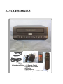
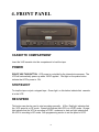
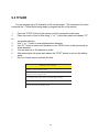
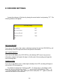
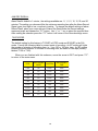
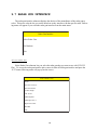
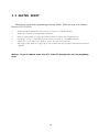
VCR 322 PLUS
MOBILE VIDEO CASSETTE
RECORDER
(NTSC & PAL)
OPERATION MANUAL
VHS
CAUTION!
RISK OF ELECTRICAL SHOCK!
DO NOT OPEN!
CAUTION! TO PREVENT ELECTRIC SHOCK, DO NOT
REMOVE COVER. NO USER SERVICEABLE PARTS
INSIDE. REFER SERVICING TO QUALIFIED PERSONNEL.
WARNING: TO PREVENT FIRE OR ELECTRIC SHOCK, DO
NOT EXPOSE THIS APPLIANCE TO RAIN OR MOISTURE!
WARNING!
THIS EQUIPMENT GENERATES, USES, AND CAN RADIATE RADIO FREQUENCY AND IF
NOT INSTALLED AND USED IN ACCORDANCE WITH THE INSTRUCTIONS MANUAL, MAY
CAUSE INTERFERENCE TO RADIO COMMUNICATIONS. IT HAS BEEN TESTED AND FOUND
TO COMPLY WITH THE LIMITS FOR A CLASS A COMPUTING DEVICE PURSUANT TO
SUBPART J OF PART 15 FCC RULES, WHICH ARE DESIGNED TO PROVIDE REASONABLE
PROTECTION AGAINST SUCH INTERFERENCE WHEN OPERATED IN A COMMERCIAL
ENVIRONMENT.
OPERATION OF THIS EQUIPMENT IN A RESIDENTIAL AREA IS LIKELY TO CAUSE
INTERFERENCE IN WHICH CASE THE USER AT HIS OWN EXPENSE WILL BE REQUIRED
TO TAKE WHATEVER MEASURES MAY BE REQUIRED TO CORRECT THE INTERFERENCE.
Copyright (c)1999
TransAmerican International, Inc.
CONTENTS
1. FEATURES ...................................................................................................................... 6
2. SPECIFICATIONS ........................................................................................................... 7
3. ACCESSORIES ............................................................................................................... 8
4. FRONT PANEL ................................................................................................................ 9
5. REAR PANEL ................................................................................................................ 11
6. WIRED REMOTE CONTROL ........................................................................................ 12
7. IR REMOTE CONTROL ................................................................................................. 15
8. BASIC OPERATION ...................................................................................................... 17
9. PROGRAMMING ........................................................................................................... 18
9.1 ACCESSING MAIN MENU .......................................................................................... 18
9.2 TIME & DATE SETUP ................................................................................................. 19
9.3 TITLER ......................................................................................................................... 21
9.4 MESSAGES ................................................................................................................. 22
9.5 RECORD SETTINGS ................................................................................................... 24
9.6 DISPLAY SETTINGS ................................................................................................... 26
9.7 RADAR GUN INTERFACE .......................................................................................... 29
9.8 MASTER RESET ......................................................................................................... 31
10. TROUBLESHOOTING ................................................................................................. 32
AVE’s LIMITED EQUIPMENT WARRANTY FOR VCR-322-PLUS. ................................ 33
5
1. FEATURES
•
•
•
•
•
•
•
•
•
•
•
•
•
•
•
•
•
IR Remote On Screen Programming
Universal Time/date Display, Programmable ON/OFF
3 Text Programmable On Screen Message Inputs
20-character programmable title.
Tape speed selection (SP/EP)
Recycle recording on/off - Power Up Record
Programmable display window position and 10 gray scales.
Master reset sub-menu
Tape insert auto recording detection
Alarm Dwell 0-3 Min.
Radar Gun Interface
Record Protection
Low Power Mode
On Screen Time Remaining
End Of Tape (EOT) Power Output
Switched 12 VDC Output
Optional Wired Remote
6
2. SPECIFICATIONS
Description
Specification
Video Input
Video Output
1 P-P 75 ohm Terminated
1 V P-P into 75 ohm Terminated, 2 V P-P
Unterminted
220 lines B&W and Color
42 dB
-5 dBm
38 dB
150Hz-8Khz
-5 Deg °C to 40 Deg °C
0.7 Amp
12 to 14 VDC
250W X 94H X 260D mm
IR wireless remote, Car Cord, battries, 12VDC
adaptor
Hi-Z or High Impedance
Normally Open Mode - closure to ground trig
gers alarm mode. Normally Closed Mode must
be shorted and when opened triggers alarm.
Open Collector, Normally Open
Imax=20ma@ 12 VDC max
RS-232
Horizontal Resolution
Video S/N
Audio Output
Audio S/N
Audio Response
Operation Temperature
Power Draw
Voltage
Dimensions
Accessories
Alarm Input
EOT End of Tape Output
Rader Gun Input
7
3. ACCESSORIES
Included accessories: • IR Remote Control
• Cigarette Cord Adaptor
• A/V Cables
• 2 AAA Batteries
• 110VAC Adapter to 12VDC (NTSC Only)
8
4. FRONT PANEL
CASSETTE COMPARTMENT
Insert the VHS cassette into this compartment to load the tape.
POWER
DONOT USE THIS BUTTON. VCR power is controlled by the internal microprosser. The
VCR will automatically power up when 12VDC applied. Red light on the power button
indicate that VCR’s power is ON.
STOP/EJECT
To stop the tape or eject a stopped tape. Green light on this button indicate that cassette
is in the VCR.
REC/SPEED
This button can also be used to start recording manually. A Dim Red light indicates that
the VCR speed is on SP mode. Green light indicate that VCR is in LP/EP mode. Orange
light indicate that the VCR is recording in LP/EP mode and a dark red light indicate that
the VCR is recording in SP mode. See programming section to set the speed of VCR.
9
SENSOR
This sensor receives the infrared signal from the remote control.
REWIND
Use this button to rewind the tape in the stop mode or to perform a reverse picture search
in the play mode. A green light indicate that the VCR is rewinding the tape.
PLAY
Use this button to start the play back mode. A green light on this button indicate that the
VCR is in the Play back mode.
FAST FORWARD
Use this button to fast forward the tape from stop mode or to perform a forward picture
search during play back. A green light on this button indicate that VCR is fast forwarding
the cassette.
AUTO REPEAT
When the tape ends and auto repeat is on then the VCR automatically starts rewinding the
tape and to starts replay. A red light on this button indicates that the AUTO REPEAT is
ON. The tape will auto rewind and play again indefinitely while in this mode.
10
5. REAR PANEL
Power:
VCR-322+ Rear View
VCR -322 Plus takes 12-14 V DC adaptor that connects to the rear of the VCR via the DB25 connector or the DC coax jack.
Audio Output:
Connect the Audio output of the VCR to the audio input of the monitor.
Video Output:
Connect the Video output of the to Video input of the monitor.
Audio Input:
Connect audio output from the audio source to the Audio input of the VCR.
Video Input:
Connect the video output of the camera or other video source to the video input of the
VCR.
Pinout for DB25 FEMALE
MESSAGE 1
12 VDC SW
PWR TRIG IN
MESSAGE 2
MESSAGE 3
PROG 3 IN
12 VDC IN
PROG 1 IN
RxD
PROG 2 IN
RESET IN
FAN OUT
11
GROUND
GROUND
GROUND
SPEEDOMETER IN
ALM REC IN
IR REMOTE IN
EOT OUT
12 VDC IN
LIGHT OUT
TxD
POWER OUT
HEATER OUT
REC OUT
6. WIRED REMOTE CONTROL
If the VCR-322 Plus is located in a place inaccessible by IR remote then you may have to
build and connect a wired remote to your VCR or can purchase Rm-322 wired remote. To do
this you will have to wire the 4 programming buttons shown below to the DB 25 connector on
the rear of the VCR. To access the VCR function remotely you must purchase an FR-9 PCB
from from AVE and wire buttons to the PCB and use the 2 wire IR in connection. You may
also build a wired remote with all VCR-322 features using the following equipments from a
local electronics distributor.
•
•
•
•
•
Momentary push buttons
Electronics enclosure
4- light emitting diodes
4 1K 1/4 watt resistors
DB 25 connector
4 buttons are necessary to access the on-screen programming menu of the VCR-322,
and must be wired according to the following diagram.
Programming Buttons
Pin 15-Reset
Reset
Pin 20-Set
Set
Pin 16-Up
momentary
pushbuttons
Up
Pin 18-Down
Down
Ground-use Pins 10, 11, 12, or 13, whichever is available
These 3 buttons are optional
Pin 9-Alarm Record
Alarm Record
Pin 22-Message 2
Message 2
Pin 25-Message 1
momentary
pushbuttons
Message 1
Ground-use Pins 10, 11, 12, or 13
The 4 Mode LED Indicators are optional
Pin 7-End of Tape
1K
Pin 5-Low Tape
Pin 3-Power
1K
End of Tape
Low Tape
Power
1K
Pin 1-Record
Record
1K
Anode side of LEDs to +12V Pin 23
12
+12V
GROUND
GROUND
MESSAGE 1
GROUND
GROUND
GROUND
MESSAGE 2
ALARM RECOR
IR IN
END OF TAPE
PROG 3 SET
PROG 1 DOWN
LOW TAPE
TxD
POWER OUT
RxD
PROG 2 UP
RESET
REC OUT
A w ired remote can also use in place of IR remote to allow simple changing of display
setting as well as the on screen programing of the VCR. Follow the important programing
steps to change the display settings.
Changing the Gray scale
Down
Up
Set
Reset
1) Press and hold the Down button
2) Press and release the Reset button
3) Release the Down button
4) Press Down or Up to select the Gray scale
5) When choice is made, press and release the Reset button
13
Changing the Horizontal Position
Down
Up
Set
Reset
1) Press and hold the Up button
2) Press and release the Reset button
3) Release the Up button
4) Press Down or Up to move the text block
5) When choice is made, press and release the Reset button
Changing the Vertical Position
Down
Up
Set
Reset
1) Press and hold the Set button
2) Press and release the Reset button
3) Release the Set button
4) Press Down or Up to move the text block
14
7. IR REMOTE CONTROL
POWER:
Don’t use this button. VCR power is controlled by the
internal microprocessor. The VCR will automatically
power up when 12VDC is applied to the VCR.
REC:
Use the combination of these two buttons pressed
simultaneously to manually start recording.
PAUSE/STILL
Press during the recording to pause recording. Press
during the playback to freeze the picture.
Caution: If this button is held for 6 seconds then it will
master reset the VCR and clear all the programming to
factory default.
SP/EP
Don’t use this button. Recording speed can only be
set in the onscreen programming mode.
15
STOP
Press this button to stop a running tape. Alternatively press and hold that button for 3 to 5
seconds to access in the programming mode.
PLAY
Press this button to start the play back mode.
REW
To rewind the tape during the stop mode and to reverse picture search in play back mode.
FAST FORWARD
To fast forward the tape during the stop mode and forward picture search in the play back
mode. In programming mode use this button to access the menu selection.
TRACKING
Use (+) or (-) button to manually adjust the tracking of the picture. In the programming
mode use these buttons to move the cursor upward and downward.
16
8. BASIC OPERATION
Insert Cassette:
n
Power up the VCR.
n
Insert the tape in to the cassette compartment until VCR pulls cassette in.
WARNING : Do not force the tape in the mechanism or this will demage the VCR. If 12
VDC is not applied to the VCR it will not accept the tape.
Start Recording
n
Alternatively, Press and release the REC/SPEED button on the front panel or on the
IR Remote control to start recording.
Stop Recording
n
Press the Stop/ Eject button from the front panel or the Stop button of the IR Remote control to stop recording.
Playback
n
Press and release the Play button either from the front panel or from the IR Remote
control.
Ejecting the Tape
n
Press the Stop/ Eject button once to stop the tape then press and Stop/Eject button
again to eject the tape.
17
9. PROGRAMMING
9.1 ACCESSING MAIN MENU
The VCR-322 Plus can be programmed via the IR wireless or wired remote control. You will need
a composite video source in and a monitor connected to be able to see the programming menu.
Following table shows the comparsion of accessing the programing menu using the IR remote and
wired remote control.
FUNCTION
Mian Menu
IR REMOTE
WIRED REMOTE
Hold ’STOP’ button for 3 sec
Hold ’UP’ and ’DOWN’ button and press
and release ’RST’ button and then release
’UP’ and ’DOWN’ button.
Cursor up
’+’ button
’UP’ button
Cursor down
’- ’ button
’DWN’ button
’PAUSE/ STILL’ button
’SET’ button
Selecting an option
This user guide is written under the assumption that user is using IR remote control to access the programming menu of the VCR-322 Plus, Press and hold the STOP button for
approximately 3 seconds. The following program menu will appear:
Main Menu
Set Time/Date
Titler
Messages
Record Setting
Display Setting
Rader Gun Inteface
Master Reset
Exit
18
9.2 TIME & DATE SETUP
An Internal clock generates time and date that is super imposed on the monitor
screen. After the clock is set, the date and time modes are displayed on the monitor
screen (live picture).
Display Time & Date on Screen
1
2
3
4
5
Under “Display Time & Date” menu place the cursor in front of T/D display and
press “ F.F” button of the remote control.
Press “+” or “-” button to select “ON” or “OFF”.
Press the “F.F” button again to select your selection.
To exit out of Display Time & Date, place cursor in front of “Exit” and press “F.F”
button.
Exit out of all the menus to activate above selection.
Note: Selecting “OFF” will turn off “Time & Date” display.
Time / Da t e
T/D Display
ON
Time Format
12 Hour
Date Format
MM/DD/YY
Set Time/Date
Reset Time/Date
Exit
Selecting Time Format
1
2
3
4
5
Place the cursor in front of “Time Format” and press and release the “F.F” button.
Cursor will start blinking.
Now push “+” or “-” button to select “12” or “24” time display mode.
After selecting the desired selection press and release the “F.F” button.
Exit out from all menus to activate your selection.
Selecting Date Format
1
2
3
Under the “Time & Date” menu place the cursor in front of “Date Format” and press
remote controls “ F.F” button.
Cursor will start blinking.
Chose the format from the selection yy/mm/dd or mm/dd/yy or dd/mm/yy by pressing
either “+” or “-” button.
19
4
Exit out from all the menus to activate your selection.
Set Time & Date
1
2
Under the “Time & Date” menu, place the cursor in front of “Set Time/Date” and
press “F.F” button.
Time and Date window pop on the screen as shown in the figure below.
1:11:37P
3
4
5
6
1/01/98TH
By pressing “+” or “-” button you can change the Time or Date.
Press “REW” and “F.F” button to move cursor either left or right side.
After setting the Time and/or Date press “STOP” button.
Exit out all the menus to activate the changes..
Reset Time & Date
1
3
4
5
Under the Time & Date menu select “Reset Time/Date”.
Press and release “F.F” button.
It will reset the time and date to factory default.
Exit out from all the menus to activate the above selection.
20
9.3 TITLER
You can program up to 20 character of title on the screen. Title is places in the video
horizontal line. Follow the following steps to program the title on the screen.
1
2
to
3
4
5
6
7
Press the “STOP” button of the remote control to access the main menu.
Place the cursor in front of titler using “+” or “-” button then press and release “F.F”
accept the selection.
Use “+” or “-” button to enter alphanumeric character.
Use “F.F” button to enter next character or use “REW” button to edit previously entered character.
You can enter up to 20 character in a title.
After entering the title press and release the “STOP” button to exit out title editing
mode.
Exit out of main menu to activate the titler.
THIN GS TO K N O W
"- " button moves the alphabet in ascending order and
numerics in descending orider.
"+" button moves the alphbets in descending order and
numerics in ascending order.
"F.F" button move the cursor toward right position.
":REW" back space.
"STO P" Exit out of editing mode
21
9.4 MESSAGES
VCR- 322 Plus has three messages input, each one a 10 character display. The
default settings for 3 messages are LTS (lights), SRN (siren), and BRK (break). The DB
25 pin connection information are shown in the figure below.
MESSAGE 1
MESSAGE 2
MESSAGE 3
To change the default setting of the messages, follow the following instruction.
1
2
Press and hold the “Stop” button of the indicator for 5 seconds, main menu will pop
up on the screen.
Place the cursor in front of “Message” using “+” or “-” button.
Set Message
Message 1
Message 2
Message 3
Exit
22
3
4
5
6
7
8
9
10
11
To make this selection press the “F.F” button, following menu will pop up on the
screen.
Place the cursor in front of message that you want to change and press “F.F” button.
Blinking cursor will appear the screen.
Enter the latter or numeric using “+” or “-” button.
After entering the first latter press “F.F” button to move the cursor in the next place.
Again use “+” or “-” button to enter next latter.
Repeat steps 6 to 8 until you enter the complete title.
After entering the title press “Stop” button that will return to Message sub menu.
Exit out of sub menu to activate the changes.
23
9.5 RECORD SETTINGS
Access the submenu of this item by placing the arrow beside it and pressing “F.F”. The
following submenu will appear:
Recording Setting
Recycle Rec
O FF
Rec- over Protect
O FF
Power- up Record
O FF
Alarm Rec Dwell
3min
Exit
RECYCLE RECORD
If you turn on this feature, then, when a videotape reaches the end, the VCR-322 Plus will
automatically rewind the tape and record over previous information.
REC OVER PROTECT
If you turn on this feature, the VCR-322 Plus will definitely NOT record over previous
information. Instead it will search the tape to find the end of the recording and begin the
new recording there.
POWER-UP REC
If you turn on this feature, and a video tape is already in the VCR, recording will begin as
soon as the VCR is powered up.
The default for these first 3 settings is OFF. To change any or all settings to ON,
place the arrow beside the item; press “F.F” and the arrow starts blinking. Press “–” or
“+” to switch between ON or OFF. Make your choice and press “F.F”. again to save the
selection and return to the submenu.
24
ALM REC DWELL’s
Alarm Dwell’s default is 1 minute; the settings available are: 0, 1, 2, 5, 10, 15, 20, and 30
minutes. The setting you choose will be the minimum recording time after the Alarm Record
Signal goes from high to low, or active to inactive. To change the default settings of alarm
Record Dwell, place your cursor infront of Alarm Rec Dwell under the Record settings
menu and press and release the “F.F” button. Use “+” or “-” key to select the required time.
After making the selection press the “F.F” button it will return to the Record settings menu.
TAPE SPEED
The default setting for this feature is T120/EP in NTSC mode and E180/SP in the PAL
mode. Consult the following table for correct mode of recording. An EP setting will triple
the number of minutes of recording time, i.e. 3 x a 120 or 160 min. tape. An SP setting
enables the exact number of minutes of recording time, as stated on the tape (usually
labeled T120 or T160).
When you are finished with this submenu, move the arrow to EXIT and press “F.F”.
to return to the main menu.
TYPE
RECORDING
MODE
SYSTEM
RECORDING
TIME
T120
SP
NTSC
2 hrs
T120
EP
NTSC
6 hrs
T160
SP
NTSC
3 hrs
T160
EP
NTSC
8 hrs
T180
EP
NTSC
9 hrs
E 180
SP
PAL
3 hrs
E 180
LP
PAL
6 hrs
E 240
SP
PAL
4 hrs
E 240
LP
PAL
8 hrs
25
9.6 DISPLAY SETTINGS
VCR 322 plus adds the alphanumeric information to the video signal from the camera
and sends it for recording or to the monitor. Display setting let you select the position, gray
scale and format of the text. Following are the option in display settings.
Display Format
Display format display alphanumeric information either on top or bottom of the screen.
To set the display follow the following instruction.
1
From remote control press the “STOP” button for 5 seconds, main menu will pop up
on the screen.
2
Under the main menu move cursor in front of “Display Setting” and press “F.F” button.
3
Display Setting menu will pop up on the screen as shown in figure below.
Display Setting
Display Format
Bottom
Horizontal Position
Verticle Position
Gray Scale/ Background
VCR Status
Exit
4
5
6
7
8
Under the Display setting menu place cursor in front of “display Format” using “+” or
“-” button.
To select display format press “F.F” button.
Now choose either “Top” or “Bottom” using “+” or “-” button.
Press “F.F” button to chose your selection.
Exit out from all the menus to activate your selection.
Horizontal Position
Horizontal position set the alphanumeric text position horizontally. Follow the steps to
set the Horizontal position.
26
1
2
3
4
5
6
Under the display setting menu place your cursor in front of “Horizontal Position”.
Press the “F.F” button to select the horizontal position.
A small box will pop up on the screen.
Press “+” or “-” button to select the appropriate position.
After selecting the position press the “F.F” button
Exit out from all the menus to activate your selection.
Vertical Position
Vertical position sets the alphanumeric text position vertically. If Display Format is set
on “TOP” then the vertical position lets you choose the position from the top of the screen
to middle of the screen. If the display format is set to the bottom then the vertical position
can be moved from the middle of the screen to the bottom of the screen. Follow the steps
to set the vertical position.
1
2
3
4
5
6
Under the Display setting place the cursor in front of vertical position.
Press the “F.F” button to make “vertical position” a selection.
A small box will pop up on the screen.
Press “+” or “-” button to select the appropriate vertical position.
After selecting the vertical position press the “F.F” button.
Exit out from all the menus to activate your selection.
Gray Scale / Background
Gray Scale/ Background color sets the gray scale and background color of the alphanumeric text on the display. Follow the procedure to set the gray scale or background
color.
1
2
3
4
5
6
Under the Display setting place the cursor in front of gray scale/ back ground color..
Press the “F.F” button to make “gray scale/ Background color” a selection.
A small box will pop up on the screen.
Press “+” or “-” button to select the appropriate gray scale or back ground color.
After selecting the gray scale or back ground color press the “F.F” button.
Exit out from all the menus to activate your selection.
Tape Counter
Tape counter if on displays the time left to record . To turn on the Tape counter follow
the instructions.
1
2
3
4
Under the Display setting place the cursor in front of tape counter.
Press the “F.F” button to make “Tape counter” a selection.
Press “+” or “-” button to turn VCR Status either “ON” or “OFF”.
After making selection press “F.F” button again.
27
5
Exit out from all the menus to activate the selection.
VCR Status
VCR Status if on displays all the VCR operating modes on the screen. Follow the procedure to
turn the VCR Status On/Off.
1
2
3
4
5
Under the Display setting place the cursor in front of VCR Status.
Press the “F.F” button to make “VCR Status” a selection.
Press “+” or “-” button to turn VCR Status either “ON” or “OFF”.
After making selection press “F.F” button again.
Exit out from all the menus to activate the selection.
28
9.7 RADAR GUN INTERFACE
The radar gun interface submenu displays the choices of the manufacture of the radar gun to
select. This menu also the lets you set the baud rate to the interface with the specific radar. Following menu will appear if you select the radar gun interface from the main menu.
Rader Gun Interface
Select Rader Gun
Set Baudrate
Exit
Select Radar Gun
Select Radar Gun submenu lets you select the radar gun that you want to use with VCR-322
Plus. To access the radar gun interface place cursor in front of Radar gun interface and press the
“F.F” button following menu will pop up on the screen.
Select Rader Gun
N one
Decatur Genesys
Decatur Hunter
Golden Eagle
LTI 20.20
MPH Python
Municipal TS- 4
Rapid Fire Plus
RG2RS
Exit
29
NONE
This is the default setting, and the setting you should leave chosen if you do not have a
radar gun connected to the VCR.
GENERIC
This accepts any RS232 data and displays it on the monitor. This can be from computers,
BAC, or other device.
DECATUR HUNTER, DECATUR GENESYS, GOLDEN EAGLE, LTI 20.20,MPH PYTHON,
MUNICIPAL , OR RAPID FIRE PLUS
These are specific types of radar guns for which settings have been programmed into the
VCR-322-Plus
RG2RS
This is American Video Equipment’s Radar Gun Interface, which, when installed with the
VCR-322-Plus, will enable the following radar guns to connect to the VCR: The RG2RS must
be purchesed separately and is not included with the VCR-322-Plus.
ACM STALKER
DECATUR HUNTER, GENESYS 1 & II
KUSTOM KR-10SP, TROOPER
MPH K-55
TARGETRON RAPID FIRE PLUS
BAUD RATE
Here you select the correct Baud Rate for your Radar gun. The choices available are: 1200,
2400, 4800, & 9600.
30
9.8 MASTER RESET
Master Reset, resets all the programming to factory default. Follow the steps to do a Master
Reset on VCR 322 PLUS.
1
2
3
4
5
6
Under the main menu place the cursor in front of “ Master Reset”.
Press “F.F” button to accept that selection.
Master reset menu will pop up on the screen as shown the figure below.
Using the “+” or “-” buttons to place cursor in front of “ Do Master Reset”
Press the “F.F” button to master reset the VCR 322 PLUS SW.
AVE Copy right menu will pop up on the screen notifying that VCR has been master
Rested.
Warning: If you do a Master reset this will clear all settings and exit the programing
mode.
31
10. TROUBLESHOOTING
No Power in the VCR
Check the wiring to the battery. The Red wire of the VCR 322 PLUS SW should be connected to the positive terminal through a 3A fuse. The black wire should connect with
negative terminal of the battery.
Check the fuse. If the fuse blown, find out why the fuse blew and then replace it.
Make sure the white wire connect to the ignition and ignition switch is on. If the VCR powers up when the temporary switch is pressed, the ignition switch connection may be faulty.
Start the engine to make sure the battery voltage is high enough to power up the VCR.
No Picture on the monitor
Check the Video camera and monitor connection with the VCR. If the camera equipped
with the power indicator make sure the indicator is on.
Start the engine to make sure the battery voltage is high enough to power the VCR.
No Picture or fuzzy but audio is clear
The head may require cleaning. Use a cleaning tape to clean VCR head. Replace all the
worn or dirty tapes.
VCR will not Record
Make sure that video tape is not write protected.
Start the engine to make sure the battery voltage is high enough to power the VCR.
Power light is blinking
The VCR has detected a faulty or jammed tape. Try to un jam the tape and remove it from
VCR. Be careful not to damage the VCR. Do not poke screw drivers or other tools into the
VCR.
32
AVE’S LIMITED EQUIPMENTWARRANTY
FOR VCR-322 PLUS.
AVE’s Products are guaranteed to be free of defects in workmanship and material. If any
failure, resulting from either workmanship or material defects should occur under normal
and proper usage within the period stated below for each product form the original provable
date of purchase, such failure should be repaired at no cost to the buyer for labor and if the
defective product(s) is sent to AVE.
VCR 322 PLUS: One (1) year electrical parts, ninety (90) days mechanical parts, ninety
(90) days labor, ninety (90) days on video heads.
This AVE warranty does not cover the following:
Products received for repair without an RMA number, sales or delivery receipt showing
date of purchase by original customer.
Damages caused by incorrect use, carelessness, unauthorized alterations, improper
Storage or unauthorized service installation or repairs.
Damage caused by fire, flood, lighting, vandalism, collision, act of God, or other events
beyond the control of AVE.
External parts such as cabinet and key pad.
Damages resulting from loss of use, loss of time or inconvenience, cost of temporary
replacement units or spares, property damage caused by this unit or its failure to work, or
any other incidental or consequential damages.
Hostile operating environments.
In transit damage claims, improper handling by carrier of post offices.
Products or parts thereof which have had serial numbers removed, altered or defaced.
Damage defect or failure caused by or resulting from the operation of the unit by incorrect
voltages.
The use of components that do not meet AVE specifications.
Periodic maintenance and adjustments resulting from normal use such as video head
cleaning, mechanical part ware, etc.
Damage resulting from use of cleaning cassettes.
33
IMPORTANT: This warranty is in lieu of all other warranties, guarantees or agreements
whether expressed or implied and no person, dealer, or company is authorized to change,
modify, or extend its term in any manner what so ever.
Warranty Return Policy
Before sending any AVE product to the factory for warranty repair, the customer must
obtain an RMA number. This number must appear on the outside of the box and on any
documentation accompanying the warranty repair. When calling AVE for an RMA number,
be prepared to give a complete description of the problem, the invoice number, and the
address to return the repaired item to. The unit must be packed in the original shipping
carton or in suitable packing offering a similar degree of protection. Separate items such
as power cords, remote controls units, or transformers, should be individually wrapped so
as not to cause scratches or other damage during shipment.
Please include your name, telephone number, address, a copy of Sale receipt and a
complete description of all inoperative functions. Ship the product prepaid. AVE will pay for
the return shipping. However, AVE is not responsible for damage during shipment.
AVE will not accept any warranty repair without an RMA number.
Freight Policy
Products and Prices are shipped F.O.B. Houston, Texas.
Refused Shipments
All refused shipments will be subject to a 15% restocking fee and freight charges.
Shipping and Return Policy and Procedure
We are fully inspected our products to insure quality and carefully packed for delivery to you in
good condition. In case that you are not satisfied with our products and must return them, please
follow our Return Policy and Procedure.
•
•
•
•
•
•
No return is accepted after 30 days from the date of purchase.
Products returned for credit must be in unused condition and contained in its orignal package.
All return other than the products under the AVE manufacture warranty are subjected to 15%
restocking and freight charges.
Call our customer service toll free number to obtain the RMA number (Return Material Authorization) prior to the shipment of the product to return.
The RMA number must be clearly displayed on all the shipping labels.
The RMA number is VALID ONLY FOR 15 DAYS from the issued date.
NOTE: The RMA number is required for all returned products, i.e. warranty and non-warranty products for services
and repair.
34
35