1
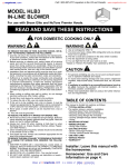
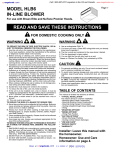
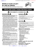
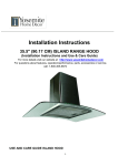
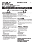
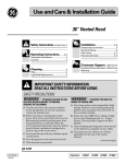
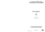
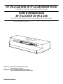
30" (76.2 CM) AND 36" (91.4 CM) RANGE HOOD
Installation Instructions and Use & Care Guide
HOTTE D’ASPIRATION DE
30" (76,2 CM) ET 36" (91,4 CM)
Instructions d’installation et Guide d’utilisation et d’entretien
Table of Contents/Table des matières............................................................................. 2
IMPORTANT: READ AND SAVE THESE INSTRUCTIONS.
FOR RESIDENTIAL USE ONLY.
IMPORTANT : LIRE ET CONSERVER CES INSTRUCTIONS.
POUR UTILISATION RÉSIDENTIELLE UNIQUEMENT.
99044505A/W10240580A
TABLE OF CONTENTS
TABLE DES MATIÈRES
RANGE HOOD SAFETY .................................................................2
INSTALLATION REQUIREMENTS ................................................4
Tools and Parts ............................................................................4
Location Requirements ................................................................4
Venting Requirements..................................................................5
Electrical Requirements ...............................................................7
INSTALLATION INSTRUCTIONS ..................................................7
Prepare Location..........................................................................7
Prepare Range Hood ...................................................................9
Install Range Hood.....................................................................10
Make Electrical Connection .......................................................11
Complete Installation .................................................................11
RANGE HOOD USE......................................................................12
Range Hood Controls ................................................................12
RANGE HOOD CARE ...................................................................12
Cleaning......................................................................................12
ASSISTANCE OR SERVICE.........................................................13
In the U.S.A. ...............................................................................13
In Canada ...................................................................................13
WARRANTY ..................................................................................14
SÉCURITÉ DE LA HOTTE DE CUISINIÈRE ...............................15
EXIGENCES D'INSTALLATION ...................................................17
Outillage et pièces......................................................................17
Exigences d'emplacement.........................................................17
Exigences concernant l'évacuation ...........................................18
Spécifications électriques ..........................................................19
INSTRUCTIONS D'INSTALLATION.............................................20
Préparation de l'emplacement...................................................20
Préparation de la hotte...............................................................22
Installation de la hotte ................................................................23
Raccordement électrique...........................................................24
Achever l'installation ..................................................................24
UTILISATION DE LA HOTTE .......................................................25
Commandes de la hotte de cuisinière .......................................25
ENTRETIEN DE LA HOTTE..........................................................25
Nettoyage ...................................................................................25
ASSISTANCE OU SERVICE.........................................................26
GARANTIE.....................................................................................27
RANGE HOOD SAFETY
Your safety and the safety of others are very important.
We have provided many important safety messages in this manual and on your appliance. Always read and obey all safety
messages.
This is the safety alert symbol.
This symbol alerts you to potential hazards that can kill or hurt you and others.
All safety messages will follow the safety alert symbol and either the word “DANGER” or “WARNING.”
These words mean:
DANGER
WARNING
You can be killed or seriously injured if you don't immediately
follow instructions.
You can be killed or seriously injured if you don't follow
instructions.
All safety messages will tell you what the potential hazard is, tell you how to reduce the chance of injury, and tell you what can
happen if the instructions are not followed.
2
IMPORTANT SAFETY INSTRUCTIONS
WARNING: TO REDUCE THE RISK OF FIRE, ELECTRIC
SHOCK, OR INJURY TO PERSONS, OBSERVE THE
FOLLOWING:
■ Use this unit only in the manner intended by the
manufacturer. If you have questions, contact the
manufacturer.
■ Before servicing or cleaning the unit, switch power off at
service panel and lock the service disconnecting means to
prevent power from being switched on accidentally. When
the service disconnecting means cannot be locked,
securely fasten a prominent warning device, such as a tag,
to the service panel.
■ Installation work and electrical wiring must be done by
qualified person(s) in accordance with all applicable codes
and standards, including fire-rated construction.
■ Sufficient air is needed for proper combustion and
exhausting of gases through the flue (chimney) of fuel
burning equipment to prevent backdrafting. Follow the
heating equipment manufacturer's guideline and safety
standards such as those published by the National Fire
Protection Association (NFPA), the American Society for
Heating, Refrigeration and Air Conditioning Engineers
(ASHRAE), and the local code authorities.
■ When cutting or drilling into wall or ceiling; do not damage
electrical wiring and other utilities.
■ Ducted fans must always be vented outdoors.
CAUTION: For general ventilating use only. Do not use
to exhaust hazardous or explosive materials and vapors.
CAUTION: To reduce risk of fire and to properly exhaust
air, be sure to duct air outside - do not vent exhaust air into
spaces within walls or ceilings, attics or into crawl spaces,
or garages.
WARNING: TO REDUCE THE RISK OF FIRE, USE ONLY
METAL DUCTWORK.
WARNING: TO REDUCE THE RISK OF A RANGE TOP
GREASE FIRE:
Never leave surface units unattended at high settings.
Boilovers cause smoking and greasy spillovers that may
ignite. Heat oils slowly on low or medium settings.
■ Always turn hood ON when cooking at high heat or when
flambeing food (i.e. Crepes Suzette, Cherries Jubilee,
Peppercorn Beef Flambé).
■ Clean ventilating fans frequently. Grease should not be
allowed to accumulate on fan or filter.
■ Use proper pan size. Always use cookware appropriate for
the size of the surface element.
WARNING: TO REDUCE THE RISK OF INJURY TO
PERSONS IN THE EVENT OF A RANGE TOP GREASE
FIRE, OBSERVE THE FOLLOWING:a
■ SMOTHER FLAMES with a close fitting lid, cookie sheet, or
metal tray, then turn off the burner. BE CAREFUL TO
PREVENT BURNS. If the flames do not go out
immediately, EVACUATE AND CALL THE FIRE
DEPARTMENT.
■ NEVER PICK UP A FLAMING PAN - you may be burned.
■ DO NOT USE WATER, including wet dishcloths or towels a violent steam explosion will result.
■ Use an extinguisher ONLY if:
– You know you have a class ABC extinguisher, and you
already know how to operate it.
– The fire is small and contained in the area where it
started.
– The fire department is being called.
– You can fight the fire with your back to an exit.
a
Based on "Kitchen Fire Safety Tips" published by NFPA.
■ WARNING: To reduce the risk of fire or electrical shock,
do not use this fan with any solid-state speed control
device.
■
SAVE THESE INSTRUCTIONS
3
INSTALLATION REQUIREMENTS
Tools and Parts
Gather the required tools and parts before starting installation.
Read and follow the instructions provided with any tools listed
here.
Tools needed
■
Drill
■
1¹⁄₄" (3.0 cm) drill bit
■
¹⁄₈" (3.0 mm) drill bit for pilot holes
■
Pencil
■
Wire stripper or utility knife
■
Tape measure or ruler
■
Caulking gun and weatherproof caulking compound
■
Flat-blade screwdriver
■
Phillips screwdriver
For vented installations, you also need:
■ Saber or keyhole saw
■
Vent clamps
■
Metal snips
■
Compass or 8" (20.3 cm) circle template
Parts supplied
Remove parts from package. Check that all parts are included.
■ Filter
■
4 - #10 x ⁵⁄₈" mounting screws
■
7" (17.8 cm) round transition plate
■
7" (17.8 cm) damper/vent connector
■
3¹⁄₄" x 10" (8.3 x 25.4 cm) damper/vent connector
Location Requirements
IMPORTANT: Observe all governing codes and ordinances.
■ It is the installer’s responsibility to comply with installation
clearances specified on the model/serial rating plate. The
model/serial rating plate is located inside the range hood on
the rear wall.
■
Range hood location should be away from strong draft areas,
such as windows, doors and strong heating vents.
■
Cabinet opening dimensions that are shown must be used.
Given dimensions provide minimum clearance. Consult the
cooktop/range manufacturer installation instructions before
making any cutouts.
■
Grounded electrical outlet is required. See “Electrical
Requirements” section.
■
The hood is factory-set for vented installations. For nonvented (recirculating) installations, charcoal filter pad Part
Number 4396846 is available from your dealer.
■
All openings in ceiling and wall where range hood will be
installed must be sealed.
For Mobile Home Installations
The installation of this range hood must conform to the
Manufactured Home Construction Safety Standards, Title 24
CFR, Part 328 (formerly the Federal Standard for Mobile Home
Construction and Safety, title 24, HUD, Part 280) or when such
standard is not applicable, the standard for Manufactured Home
Installation 1982 (Manufactured Home Sites, Communities and
Setups) ANSI A225.1/NFPA 501A*, or latest edition, or with local
codes.
Product Dimensions
Parts needed
For direct wire installation
■ UL listed or CSA approved ¹⁄₂" (12.5 mm) strain relief
■
Two 40-watt maximum incandescent light bulbs
■
Power supply cable (if needed, for direct wire installation)
For power supply cord installation
UL Listed Power Supply Cord Connection Kit marked for
range hood use.
■
■
Two 40-watt maximum incandescent light bulbs
For vented installations you also need:
■ 3¹⁄₄" x 10" (8.3 x 25.4 cm) or 7" (17.8 cm) round metal venting
■
7" (17.8 cm) round damper, if using 7" (17.8 cm) round vent
system
For cabinets with recessed bottoms:
Two 2" (5.1 cm) wide filler strips. Length and thickness
determined by recess dimensions.
■
■
4
Four flat head wood screws or machine screws with washers
and nuts (to attach filler strips).
12"
(30.5 cm)
9"
(22.9 cm)
1 ¹⁄₂"
(3.8 cm)
1"
(2.5 cm)
2"
(5.1 cm)
6"
(15.2 cm)
³⁄₄"
(1.9 cm)
1 ¹⁄₂"
(3.8 cm)
7 ¹⁄₂"
(19.1 cm)
³⁄₈"
(9.5 mm)
29 ⁷⁄₈" (75.9 cm) - 30" (76.2 cm) model
35 ⁷⁄₈" (91.1 cm) - 36" (91.4 cm) model
17 ¹⁄₂"
(44.5 cm)
For the most efficient and quiet operation:
Use no more than three 90° elbows.
Installation Clearances
■
30" (76.2 cm) or
36" (91.4 cm) min.
cabinet opening width
18"(45.7 cm) min.
24" (61.0 cm)
suggested max.
bottom of cabinet
to cooking surface
■
Make sure there is a minimum of 24" (61 cm) of straight vent
between the elbows if more than 1 elbow is used.
■
Do not install 2 elbows together.
■
Use clamps to seal all joints in the vent system.
■
The vent system must have a damper. If roof or wall cap has a
damper, do not use damper supplied with the range hood.
■
Use caulking to seal exterior wall or roof opening around the
cap.
Cold Weather Installations
13" (33.0 cm)
cabinet depth
18" (45.7 cm)
min. clearance
upper cabinet
to countertop
An additional back draft damper should be installed to minimize
backward cold air flow and a thermal break should be installed to
minimize conduction of outside temperatures as part of the vent
system. The damper should be on the cold air side of the thermal
break.
The break should be as close as possible to where the vent
system enters the heated portion of the house.
Makeup Air
Local building codes may require the use of make up air systems
when using ventilation systems greater than specified CFM of air
movement. The specified CFM varies from locale to locale.
Consult your HVAC professional for specific requirements in your
area.
36" (91.4 cm)
base cabinet
height
Venting Methods
Vent system can terminate either through the roof or wall. Use
3¹⁄₄" x 10" (8.3 x 25.4 cm) with a maximum vent length of
35 ft (10.7 m) or 7" (17.8 cm) round vent with a maximum length
of 50 ft (15.2 m) for vent system.
NOTE: Flexible vent is not recommended. Flexible vent creates
back pressure and air turbulence that gently reduces
performance.
Roof Venting
Venting Requirements
Wall Venting
(vented models only)
■
■
Vent system must terminate to the outdoors, except for nonvented (recirculating) installations.
A
Do not terminate the vent system in an attic or other enclosed
area.
B
■
Do not use a 4" (10.2 cm) laundry-type wall cap.
■
Use a 7" (17.8 cm) round metal vent or a 3¹⁄₄" x 10"
(8.3 x 25.4 cm) rectangular metal vent. Rigid metal vent is
recommended. Plastic or metal foil vent is not recommended.
■
The length of vent system and number of elbows should be
kept to a minimum to provide efficient performance.
D
C
A. 7" (17.8 cm) round vent or a
3¹⁄₄" x 10" (8.3 x 25.4 cm) vent
through roof
B. Round vent: use 7" (17.8 cm)
round damper
(purchased separately)
C. 18" (45.7 cm) - 24" (61.0 cm)
above cooking surface
D. Roof cap
A
B
D
C
A. 7" (17.8 cm) round vent or a
3¹⁄₄" x 10" (8.3 x 25.4 cm) vent
through the wall
B. 3¹⁄₄" x 10" (8.3 x 25.4 cm)
through the wall
C. 18" (45.7 cm) - 24" (61.0 cm)
above cooking surface
D. Wall cap
5