1
Model 98RK-1 & Model 9816
Rackmount Intelligent Pressure Scanner
User’s Manual
August 2009
NetScanner™ System
www.PressureSystems.com
©
This User’s Manual is a copyright product of Pressure Systems, Inc., 2009
Permission is hereby granted to make copies and distribute verbatim copies of
this manual, provided the copyright notice and this permission notice are preserved on all copies.
Pressure Systems, Inc.
98RK-1 & 9816 User’s Manual©
Chapter 1
General Information
1.1
Introduction
This User’s Manual will:
Explain the electrical and pneumatic pressure connections for the Model 98RK-1
Scanner Interface Rack and Model 9816 Rackmount Intelligent Pressure Scanners.
Provide computer set-up instructions to make a proper Ethernet connection on most
Windows® -based personal computers.
Instruct you on using the PSI start-up software to manipulate and acquire data from each
Model 9816 scanner in the rack.
Instruct you on how to program each module with computer software.
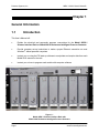
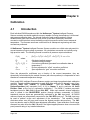
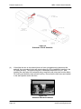
Figure 1.1
Model 98RK-1 Scanner Interface Rack with
Model 9816 Rackmount Intelligent Pressure Scanners
Page 1
www.PressureSystems.com
Pressure Systems, Inc.
98RK-1 & 9816 User’s Manual©
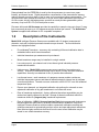
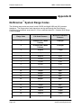
The NetScanner™ System is a comprehensive, distributed data acquisition system centered
around PSI’s proven Intelligent Pressure Scanner technology. The rackmount configuration of
this system is comprised of Model 98RK-1 Scanner Interface Racks, each housing up to eight
(8) Model 9816 Rackmount Intelligent Pressure Scanners networked via the Ethernet
interface. The 98RK-1 chassis provides communication, power supply and pneumatic
connections to the 9816 scanners. The 98RK-1 utilizes an integral gigabit switch to connect all
scanners to a host computer. Each 98RK-1 can also provide power and communication to as
many as three (3) remotely connected NetScanner modules such as the Model 9116
Pneumatic Intelligent Pressure Scanners, Model 9022 All-Media Intelligent Pressure
Scanners, Model 9046 Intelligent Temperature Scanners, and Model 903x Pressure
Controllers. Refer to their respective datasheets for more information on these NetScanner
System components. A typical system configuration is shown in Figure 1.2.
Each Model 9816 Rackmount Intelligent Pressure Scanner module integrates sixteen (16)
silicon piezoresistive pressure sensors and a unique patented calibration manifold with an
onboard
32-bit microprocessor. This provides compensated engineering unit (EU) data output via
the Ethernet interface. Each pressure sensor is packaged with an integral EEPROM for storage
of calibration data unique to the sensor. Integrating the EEPROM within the sensor enables
simple ‘plug and play’ field replacement of transducers with automatic uploading of sensor data
during system power-up.
Figure 1.2
Typical NetScanner System Configuration
Page 2
www.PressureSystems.com
Pressure Systems, Inc.
98RK-1 & 9816 User’s Manual©
Data uploaded from the EEPROMs is used by the microprocessor to correct zero, span,
linearity, and thermal errors. Digital temperature compensation of the piezoresistive sensors
reduces thermal errors by a factor of ten or more over conventional sensor compensation. The
microprocessor also controls the execution of on-line zero or span calibrations upon request.
On-line re-zero virtually eliminates sensor zero drift error and provides guaranteed system
accuracy of up to ±0.05% FS (Full Scale) after re-zero.
Firmware within each 9816 scanner provides the capability to sample using up to three (3) scan
lists concurrently at rates up to 100 measurements per channel per second. The NetScanner™
System is supplied with software for PC compatible computers.
1.2
Description of the Instruments
Model 9816 Intelligent Pressure Scanners are available with 16 (sixteen) measurement
channels, each with individual pneumatic transducers per channel. The most distinctive
features are highlighted below:
Pre-calibrated Transducer - a memory chip containing full thermal calibration data is
embedded within each internal transducer.
Individual transducer per measurement input channel.
Mixed transducer ranges may be installed in a single module.
Low cost per point - per-channel cost is less than a typical industrial pressure
transducer/transmitter.
High accuracy - Model 9816 pressure scanners are capable of accuracies up to
±0.05%. Accuracy is maintained through use of built-in re-zero and span calibration
capabilities. Accuracy is maintained for six (6) months after calibration.
Low thermal errors - each transducer of a pressure scanner module contains an
individual temperature sensor and thermal calibration data for internal use by software
correction algorithms. Thermal errors are reduced to ±0.001%FS/ºC over the calibrated
temperature span.
Re-zero upon demand - an integrated calibration valve allows for automatic re-zero
adjustment calibration of dry gas transducers to null offset drift errors.
Ease of transducer replacement - factory calibrated transducer assemblies may be
stocked and rapidly replaced in the field. Storage of thermal coefficients within the
transducer allows for ‘plug and play’ transducer replacement.
Ease of calibration - 98RK-1 Scanner Interface Rack features pneumatic hook-ups on
the back-panel and front-panel (if ordered) to ease scanner calibration. Each 9816
Intelligent Pressure Scanner module contains a pneumatic calibration manifold and
software commands to automatically perform re-zero and span adjustment calibrations.
New offset and gain coefficients that result from the most recent calibration may be
stored in non-volatile transducer memory.
Page 3
www.PressureSystems.com
Pressure Systems, Inc.
98RK-1 & 9816 User’s Manual©
The 98RK-1 Scanner Interface Rack features a gigabit switch that significantly
increases processing capabilities and speed.
System calibration consists of zero and span calibration only at any given temperature.
Full thermal re-calibration is never necessary.
Ease of use - modules have simple command sets and provide engineering units (EU)
output. They may interface directly to a desktop or laptop computer or they may be
interconnected into a large network controlled by many types of host computers.
Connectivity - use of industry-standard TCP/UDP/IP communications network protocols
to control and read data from NetScanner™ System modules ensures compatibility with
third party hardware and software.
1.3
Options
1.3.1
Pressure Ranges
Model 9816 Intelligent Pressure Scanners contain sixteen (16) DH200 transducers. These
DH200 transducers are available with full scale pressure ranges from 10" H2O (inches of water
column) to 850 psid (2.5 kPa to 5860 kPa). Transducers with different pressure ranges may be
combined in a single module.
Please consult the Sales Department at Pressure Systems at 1-800-678-SCAN (7226) for
availability of other pressure ranges as well as other modules which may be attached to the
98RK-1 Scanner Interface Rack.
1.3.2
Manifolds and Pressure Connections
The Model 9816 sixteen-channel Intelligent Pressure Scanner is available with either a true
differential (reference per port) or common differential (single reference port) pneumatic
manifold, and are both equipped with a purge and leak-check manifold. The standard frontmount input and the optional rear-mount input for the 9816 scanner both include a rectangular
quick disconnect (QDC) plate with 0.063" (0.040" optional) bulge tubes.
Compression fittings (1/8", 1/16", or ¼" tube outside diameter (O.D.)) are available only for
common reference, front-mount scanners. True differential scanners are only available with
bulged tubulation front-mount QDCs. Consult the Sales Department at Pressure Systems for
availability of other input fittings.
Page 4
www.PressureSystems.com
Pressure Systems, Inc.
1.3.3
98RK-1 & 9816 User’s Manual©
Communication Interfaces
All Intelligent Pressure Scanners provide digitally temperature compensated and linearized
pressure data in engineering units through an Ethernet communications interface to a host
computer.
Model 9816 Intelligent Pressure Scanners have a 10Base-T Ethernet host communications
interface using industry standard TCP/UDP/IP protocols. This interface provides high data
transfer rates (10MBit/sec.) and system connectivity.
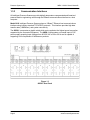
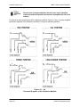
The 98RK-1 incorporates a gigabit switch which auto negotiates the highest speed connection
supported by the connected equipment. The 98RK-1 incorporates a universal input AC-DC
power supply accepting input voltages from 90-250 VAC at 50 or 60 Hz and is capable of
supporting a full complement of NetScanner products.
Figure 1.3
98RK-1 Rear Panel
Page 5
www.PressureSystems.com
Pressure Systems, Inc.
98RK-1 & 9816 User’s Manual©
Chapter 2
Installation and Set Up
2.1
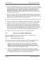
Unpacking and Inspection
Before assembling the system, use the shipping bill as a reference to ensure that all parts have
arrived. Pressure Systems takes no responsibility for equipment that is damaged during
shipment. If containers are broken, ripped, or damaged, contact the transportation carrier. If
the equipment itself appears to be damaged, contact the Repair Department at Pressure
Systems at 1-800-678-SCAN (7226).
Each shipment will contain one or more of the following components:
98RK-1 Scanner Interface Rack chassis
9816 Intelligent Pressure Scanner modules (installed in the 98RK-1, if ordered)
Start-up software (NUSS) on CD-ROM
9882 Pneumatic Blanking Unit (if purchased)
98RK-1 Scanner Interface Rack User’s Manual on CD-ROM.
2.2
Safety Considerations
It is always a good idea to wear safety glasses when operating this equipment or when working
with pressurized lines. Always ensure that high pressure lines are properly secured and that all
pneumatic lines are rated for the proper pressure and temperature environments.
Ensure that the rack Power Switch is turned OFF before plugging the Scanner Interface Rack
into a power receptacle. Always check line voltages and ensure the correct voltage for your
Scanner Interface Rack prior to plugging into the receptacle.
Page 6
www.PressureSystems.com
Pressure Systems, Inc.
98RK-1 & 9816 User’s Manual©
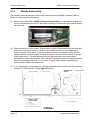
2.3
Connections and Setup
2.3.1
98RK-1 Chassis Connections with 9816 Scanners
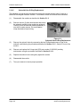
STEP 1
Ensure correct line voltage and that the Power Switch for the 98RK-1 is in the OFF
position. Connect the 98RK-1 chassis to an adequate power receptacle and connect
an Ethernet cable from the 98RK-1’s host port (TO HOST) to an optional
10/100/1000Base-T hub, switch, or directly to your computer’s Ethernet card.
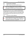
Figure 2.1 (on the next page) depicts a typical Pressure Systems’ NetScanner™ System array.
Although this figure depicts the front and back of two 98RK-1 Scanner Interface Racks,
multiple 98RK-1 Racks, with up to eight (8) scanners per rack, may be networked together.
Each chassis provides scanner power supplies and pneumatic connections as well as switch
circuitry for up to eleven (11) 10/100Base-T connections, and a 10/100/1000Base-T (gigabit)
host link. This enables each chassis to connect with the host computer as well as with up to
three (3) additional scanners (and/or standard/ calibration units) which may be externally
attached to each rack.
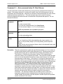
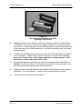
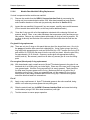
2.3.2
STEP 2
Page 7
Connections for External Modules
If you are connecting a Model 9016/9116, or 9021/9022 Intelligent Pressure Scanner,
a Model 903x Intelligent Pressure Calibrator or Standard, or a 9046 Intelligent
Temperature Scanner to the rear of your 98RK-1, connect the ruggedized circular
connector of the 9082 cable to your scanner’s connector port. Connect the other end
of the same cable to one of the ports on the rear of the 98RK-1 chassis labeled
“Remote NetScanner Module Interface.” (See Figure 2.1)
www.PressureSystems.com
Pressure Systems, Inc.
98RK-1 & 9816 User’s Manual©
Figure 2.1
Typical Hook-up Arrangement
Using the 98RK-1 Scanner Interface Rack
Page 8
www.PressureSystems.com
Pressure Systems, Inc.
2.3.3
98RK-1 & 9816 User’s Manual©
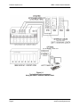
Network Communications Hookup
The 98RK-1 Scanner Interface Rack chassis has an Ethernet connector port on the rear of
the unit through which all scanners in the rack may be connected to the network or the Ethernet
card in your PC or work station. This port is labeled “ TO HOST” (using an RJ-45 connector).
Similarly, every Model 9016, 9116, 9021, or 9022, 903x and 9046, has an Ethernet connecting
port using TCP/IP transmission protocol through their single circular connector.
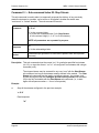
STEP 3
If required, install an Ethernet card in your computer.
STEP 4
Set up or confirm the TCP/IP protocol and address of the host computer as shown in
the following steps.
Communications via Ethernet using TCP/IP protocol uses module address designations and
requires the host computer to have a compatible address.
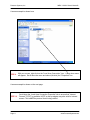
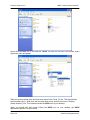
STEP 5
Find the “Network Connections” icon on "Control Panel." Double-click the icon to
arrive at the "LAN or High Speed Internet" screen. Find the "Local Area Connection"
icon and select it (Left click). Select “Properties” from the "Local Area Connection" by
right clicking the icon. A screen example is shown on the next page.
Note
STEP 6
Page 9
All of the screen examples in this User's Manual are from
Windows® XP operating system. If you are using a different
operating system and need assistance in setting up your
network, contact the Applications Support Group at
Pressure Systems.
Scroll down the “Local Area Connection” tab to ensure that "Internet Protocol TCP/IP"
is available. NOTE: a dial-up adapter may also exist for internet access. This is NOT
the protocol that is being verified.
www.PressureSystems.com
Pressure Systems, Inc.
98RK-1 & 9816 User’s Manual©
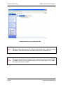
Initial Network Screen for Windows® XP
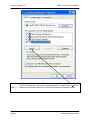
STEP 7
With your mouse, right-click on the "Local Area Connection" icon. A drop-down menu
will appear. Scroll down the menu and select (left-click) the "Properties" line.
STEP 8
Scroll down the “Local Area Connection” tab to ensure that "Internet Protocol TCP/IP"
is available. NOTE: a dial-up adapter may also exist for internet access. This is NOT
the protocol that is being verified.
Page 10
www.PressureSystems.com
Pressure Systems, Inc.
98RK-1 & 9816 User’s Manual©
A screen example is shown here.
STEP 9
With your mouse, right-click on the "Local Area Connection" icon. A drop-down menu
will appear. Scroll down the menu and select (left-click) the "Properties" line.
A screen example is shown on the next page.
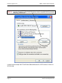
STEP 10
Page 11
Scroll down the “Local Area Connection Properties” tab to ensure that "Internet
Protocol TCP/IP" is available. NOTE: a dial-up adapter may also exist for internet
access. This is NOT the protocol that is being verified.
www.PressureSystems.com
Pressure Systems, Inc.
STEP 11
Page 12
98RK-1 & 9816 User’s Manual©
If the TCP/IP protocol is not found, it must be installed. To install, select "Install" as
shown on the "General" tab on the "Local Area Connection Properties" screen.
www.PressureSystems.com
Pressure Systems, Inc.
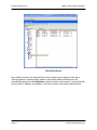
STEP 12
98RK-1 & 9816 User’s Manual©
Once the correct TCP/IP protocol is installed and verified for the proper Ethernet
card, the IP address (under TCP/IP Properties), that is compatible with the pressure
scanner(s), must be set.
A typical screen example with IP and Subnet Mask addresses for a 9816 scanner is shown on
the next page.
Page 13
www.PressureSystems.com
Pressure Systems, Inc.
STEP 13
Page 14
98RK-1 & 9816 User’s Manual©
To set the PC address: Select "Use the following TCP/IP address." It is suggested
that the IP Address read 200.xxx.yyy.zzz where xxx, yyy, and zzz are unique
locations that do not match any other address on the network. (Check with your
network administrator to see that the numbers chosen do not conflict with any other
addresses on the network.) It is suggested that the IP address should, as a default,
read 200.1.1.1. This should allow you to talk with any other modules on the
network. The Subnet mask should read 255.0.0.0. Select OK. The host computer is
now set to communicate via the Ethernet card to the 9816 module.
www.PressureSystems.com
Pressure Systems, Inc.
STEP 14
98RK-1 & 9816 User’s Manual©
Connect the Ethernet cable between the 98RK-1 “TO HOST” RJ-45 connector and
the Ethernet card of your host computer.
After you set the IP address and the subnet mask, click “OK”. You may then be prompted to
re-start your computer so that the inputs will be recognized.
The host computer and each module must have a unique Ethernet Hardware Address and a
unique IP Address. The Ethernet Hardware address is generally fixed (at manufacturing time of
the Ethernet microprocessor board inside the module). The Ethernet Hardware address is
shown on each NetScanner™ System module’s label. PSI’s Ethernet Intelligent Pressure
Scanners are capable of supporting various methods for IP address assignment, using either
the factory default or user-configured Static IP addressing or Dynamic IP address assignment.
Dynamic IP address assignment is through the use of RARP or BOOTP protocols. Unless
your application requires the use of Dynamic IP address assignments, it is strongly suggested
that the module be left configured to use the Static IP address. The default method is typically
the simplest method for using the Intelligent Pressure Scanner.
Note
After closing the TCP/IP connection to a module, the host must
wait 10 seconds before reconnecting.
The PSI software (shipped with your module(s)) is called NetScanner Unified Startup
Software (NUSS) and is designed to be compatible and operate with most Windows®-based
operating systems.
STEP 15
Insert the CD-ROM containing the software shipped with your NetScanner™ System
(NUSS) into the appropriate drive of your computer. Using your Windows®
“Start/Run” button, type D:\SETUP (or use appropriate drive designation), and
follow any on-screen instructions. This will load the NUSS software onto your hard
drive. NUSS is self-installing from your CD-ROM, or may be downloaded from the
PSI Web site (www.PressureSystems.com/netscanner_software.html). It may be
installed multiple times and on as many computers as desired.
The executable file will automatically be installed as (typically):
C:\ NUSS\NUSS.EXE
Page 15
www.PressureSystems.com
Pressure Systems, Inc.
98RK-1 & 9816 User’s Manual©
STEP 16
Turn the 98RK-1 power switch ON and wait approximately thirty (30) seconds for
the scanners to perform self-diagnostics. The scanners automatically upload the
calibration data stored within each transducer at start-up. Newly installed
transducers are automatically ready to be used without further calibration.
STEP 17
Select (double click) the executable file (NUSS.EXE) using “Windows Explorer” or
“My Computer” or select (double click) your desktop shortcut icon. (See Appendix
C for instructions on how to create a shortcut icon.)
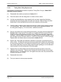
The initial screen of the NetScanner™ System software (NUSS) is shown on the next page.
At this point, the best way to see if you have correctly connected your NetScanner™ System
with the 98RK-1 Scanner Interface Rack is to observe the Host Link (LNK) light, located on
the front panel of the 98RK-1. The 98RK-1 will auto-negotiate for maximum speed connections
(up to 1 gigabit/sec) and will automatically correct for swapped signal pairs. With the LNK light
ON, the system is correctly connected to your Ethernet network or host computer. The 98RK-1
will display a yellow LNK light when it has negotiated a 10T Ethernet connection, green for 100T
or blue for a gigabit connection. The LNK light will blink during communications activities. If
the LNK light is not ON, re-trace your steps to find the connection error. You may use the “
ping” utility as described in the Chapter 6, Troubleshooting, in this manual to check proper
electrical connection and TCP/IP configuration.
Page 16
www.PressureSystems.com
Pressure Systems, Inc.
98RK-1 & 9816 User’s Manual©
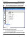
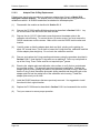
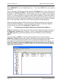
NUSS Initial Screen
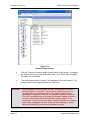
Once NUSS is selected, the Network Status Screen (shown above) appears. Note that a
"Querying Network" message briefly appears, and then the Nodes on Network box will
automatically display the each NetScanner module hooked into the network. It also shows their
serial number, IP address, and whether or not they are active (connected or disconnected).
Page 17
www.PressureSystems.com
Pressure Systems, Inc.
98RK-1 & 9816 User’s Manual©
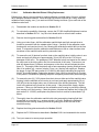
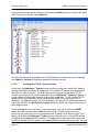
Connect to any module. (When a connection has been established, the top of the module icon
will turn yellow.)
STEP 18
Select (left click) the module's icon in the Node map. Right-click on the module's
icon (in either the Node Map or the description box), and select (left click) on
"Connect" in the pull-down menu that appears. (See screen depiction below.)
As stated above, if the module's icon does not turn yellow when selected, the module did not
connect. Some possible causes for a failure to connect are:
There is an IP address incompatibility between the host computer and the module.
There are two modules with the same IP address.
For complete instructions on using NUSS for operating your modules, please refer to the NUSS
User's Manual, available from Pressure Systems.
Page 18
www.PressureSystems.com
Pressure Systems, Inc.
2.3.4
98RK-1 & 9816 User’s Manual©
Pressure Connections
Pneumatic connections for the sixteen (16) measurement inputs of the Model 9816 Intelligent
Pressure Scanners installed in the 98RK-1 Scanner Interface Rack may be found either on the
backplane of the 98RK-1 chassis or on the 9816 front plate, depending on the particular
configuration you ordered. Additional control, purge, and calibration inputs are found on the
rear of the 98RK-1. The function of each input port is clearly engraved or printed next to each
input (see Figures 2.2, 2.3 and 2.3a, next page). Connections are through bulge tubing,
compression fittings, or special user-supplied fittings on the tubing plate. All pneumatic inputs to
these modules should contain dry, non-corrosive gas only.
As a standard, all Model 9816 Intelligent Pressure Scanners are supplied with the purge/leak
check calibration manifold. Through software commands to each 9816, this valve may be
placed in one of four positions; RUN, CAL, PURGE, or LEAK-CHARGE. See functions 0C
and 12 of the Set/Do Operating Options/Functions (‘w’) command in Chapter 3 for more
information. Pneumatic input requirements for these four operating positions are described in
following sections.
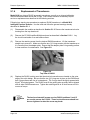
Here are some guidelines which should be followed when installing pressure connections to all
NetScanner™ System Intelligent Pressure Scanner modules.
●
It is always a good idea to wear certified safety glasses when working with pressurized
lines.
●
Ensure that your input pressure will not exceed the proof pressure ratings of the
corresponding instrument transducer. Applying excessive pressure to measurement
inputs can permanently damage the pressure transducers.
●
Ensure that all tubing material is rated for the expected pressure and environmental
conditions. Failure to use the proper tubing material may result in ruptured lines and
possible personal injury.
●
Ensure all high pressure lines are properly secured.
●
Place retaining springs over all bulge tube fittings to ensure pneumatic lines remain
attached and leak free. Springs should be pushed down on connections so that half of
the spring length extends past the tube bulge.
WARNING:
Page 19
Introduction of contaminants to the module pneumatic inputs may
damage transducers, manifolds, and O-ring seals.
www.PressureSystems.com
Pressure Systems, Inc.
98RK-1 & 9816 User’s Manual©
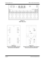
Figure 2.2
98RK-1 Rear View
Figure 2.3
Expanded View of 98RK-1 Scanner
Interface Rack Rear Manifold
Page 20
Figure 2.3a
Expanded View of Model 9816 Intelligent
Pressure Scanner Rear Manifold
www.PressureSystems.com
Pressure Systems, Inc.
2.3.4.1
98RK-1 & 9816 User’s Manual©
Supply Air
The 98RK-1 chassis requires an 80 psig minimum (125 psig maximum) dry air (or inert gas)
supply which is used to shift the 9816 internal calibration valve (in each scanner) between its
different positions. Each 98RK-1 contains a fitting marked “SUPPLY” for this input (see Figure
2.2, previous page). Internal solenoid valves in each 9816 scanner direct this supply pressure
to the proper control port on the calibration valve as required by instrument commands. The
absence of sufficient supply air to the module will prevent the calibration valve from shifting into
requested positions (i.e., RUN, CAL, PURGE, or LEAK-CHARGE). The pneumatic input
manifold (on the rear of the chassis) contains an additional two transducers to read the supply
and purge air pressures.
STEP 19
Connect 80-125 psig dry air to the chassis SUPPLY port. This is the power used to
move the internal calibration valve between the four locations; RUN, CAL, PURGE,
and LEAK-CHARGE.
WARNING:
2.3.4.2
Supply air should not exceed 125 psi (875 kPa). Excessive pressure
may damage the internal solenoids.
RUN Mode Inputs
The standard pneumatic quick disconnect ( QDC) tubing plates contain sixteen (16) numbered
pneumatic input channels. These numbered inputs are attached to corresponding pressure
transducers inside the instrument and should be pneumatically attached to the pressure
measurement points under test.
The 98RK-1 pneumatic backplane also contains inputs labeled RUN REF (RUN REF 1
through RUN REF 8). With the common reference manifold, RUN REF 1 is the reference port
for any 9816 scanner installed in 98RK-1 slot #1 (leftmost position when viewing from the front
of the 98RK-1). RUN REF 8 is the corresponding reference for any 9816 scanner installed in
98RK-1 slot #8. The RUN REF inputs are pneumatically connected to the reference side of all
internal DH200 pressure transducers, as shown in Figure 2.4 (next page).
Page 21
www.PressureSystems.com
Pressure Systems, Inc.
98RK-1 & 9816 User’s Manual©
Figure 2.4
Optionally, the unit may be ordered with a true differential (reference per channel) manifold.
The RUN REF connection is used for situations where all channels have one reference
pressure. This input may also be left unattached to provide atmospheric reference pressure.
When using instruments with the reference per channel option (true differential), two (2)
pneumatic inputs will be provided for every numbered channel. These inputs are labeled “P” and
“R”. The “P” connection is the test pressure input. The “R” connection is the transducer
reference input pressure. Since each channel has its own reference pressure input, the RUN
REF input is not provided on the true differential tubing plate.
2.3.4.3
CAL Mode Inputs
The 9816 model (in the 98RK-1) contains pneumatic backplane inputs for CAL(CAL 1-8) and
CAL REF. When the module’s internal calibration valve is placed in the CAL/RE-ZERO position,
all DH200 transducer pressure inputs are pneumatically connected to the CAL input ports. All
DH200 reference inputs are pneumatically connected to the CAL REF input port. The CAL
input may be used to perform on-line zero adjustment of the transducers. The CAL input may
also be used for DH200 span adjustment calibrations and accuracy tests if appropriate pressure
calibrators (such as the 903x series) are available. Span calibration of multi-range scanners
may also utilize the CAL 1-8 ports if the highest applied pressure does not exceed the proof
pressure rating of any other installed transducer, otherwise the individual transducers must be
calibrated with the valve in the RUN position.
When the internal calibration valve is in the CAL/RE-ZERO position, the RUN inputs (RUN REF
and numbered input ports) are pneumatically dead-ended to prevent migration of contaminants
into the instrument.
Page 22
www.PressureSystems.com
Pressure Systems, Inc.
98RK-1 & 9816 User’s Manual©
Figure 2.5
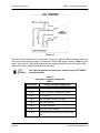
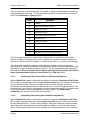
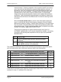
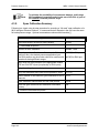
Each 9816 is manufactured with a connection to one of the eight (8) CAL port ranges, based on
the unit’s full scale pressure range. Assignment of 9816's CAL range is show in Table 2.1 (next
page). In the case of a 9816 with multiple pressure ranges installed, the unit will use the CAL
range of the lowest installed full scale pressure range.
Note
CAL port assignments are based on a pressure range, NOT 98RK-1
slot assignments.
Table 2.1
Pneumatic Connector Assignment
98RK-1
Connection
Page 23
Pressure Scanner Range Input
Cal 1
User defined
Cal 2
10" W.C.; 20" W.C.; ±1 psid, ±1.5 psid
Cal 3
±2.5; ±5 psid
Cal 4
±10; ±15 psid, ±20 psid, ±25 psid
Cal 5
±30; ±45; ±50 psid
Cal 6
±75 psid, ±100 psid
Cal 7
+150; 200; 250; 300 psid
Cal 8
500 psid, 600 psid, 650 psid, 750 psid, 850
psid
www.PressureSystems.com
Pressure Systems, Inc.
2.3.4.4
98RK-1 & 9816 User’s Manual©
PURGE Mode Inputs
9816 scanners are supplied with a purge/leak-charge feature. The purge feature allows users to
apply positive pressure to the PURGE input which will then be vented out of the user input
ports, forcing contaminants (such as moisture) out of the pneumatic input lines. (Note: on
common reference 9816 scanners, only the numbered input ports will be purged. RUN
REF is not purged). True differential 9816 scanners will purge both the run and reference input
ports for all channels. The purge supply provided to the 9816 must always be a higher pressure
than the highest pressure present on the input ports of the module. The purge supply must also
be capable of maintaining proper purge pressure at the high flow rates encountered while the
module is in the purge mode.
WARNING:
Failure to provide proper purge supply pressure may result in
migration of moisture and contaminants into the 9816 module. This
can result in permanent damage to module components.
When commanded into the PURGE position, the purge input pressure will be connected to the
numbered measurement input ports allowing for a flow of air away from the instrument. The
purge cycle should be terminated by commanding the 9816 into a non-purge mode, such as
CAL.
WARNING:
Purge cycles should NEVER be terminated by turning off the purge
supply air while in the PURGE position.
Figure 2.6
Page 24
www.PressureSystems.com
Pressure Systems, Inc.
2.3.4.5
98RK-1 & 9816 User’s Manual©
LEAK Mode Inputs
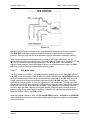
The purge/leak-charge valve design includes a leak check feature capable of testing the
integrity of user pneumatic connections as well as those within the 9816 module. For the leak
mode to be used, all RUN mode pressure inputs must be dead-ended (closed) by the user.
(Contact the PSI Sales Department for availability of an external leak check valve) When the
9816 is commanded into the LEAK/CHARGE position, the CAL 1-8 input ports will be
pneumatically connected to the module run side inputs. Common reference modules will
connect only the numbered run side inputs to CAL (RUN REF is not charged). True differential
(reference per port) modules will connect both the measurement input and reference port to
CAL. While in the LEAK position, a test pressure may be applied thought the CAL port which
will charge the dead-ended run side tubulation.
Note
Test pressures applied to the CAL port during leak check operation
must not exceed the full scale pressure of any internal transducer.
Once the lines are charged, the 9816 may be commanded back to the RUN position. This will
reattach the charged run side lines to their corresponding internal transducer. Consecutive
pressure readings from the 9816 will now allow user to determine the line leak rates. (Factory
testing allows a maximum leak rate of 2% in two (2) minutes.) Once returned to the RUN
position, lack of pressure indicates a gross leak. A slowly declining pressure indicates a slight
leak. A leak is more difficult to detect as tubing volume increases. In the case of true differential
units where both sides of the sensor are pressurized with the leak test pressure, an initial
differential pressure of 0.0 psi should be measured when the unit is placed in the RUN position.
If the measurement or RUN side of the channel leaks at a rate greater than the reference side, a
resulting negative differential pressure will be measured. Likewise, if the reference port tubing
leaks at a rate greater than the measurement side, a resulting positive differential pressure will
be measured.
Figure 2.7
Page 25
www.PressureSystems.com
Pressure Systems, Inc.
2.3.4.6
98RK-1 & 9816 User’s Manual©
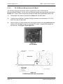
Calibration Manifold Position Detector Circuit
The transducer calibration manifold position detector circuit uses reflective infrared sensors to
sense the actual position of the manifold valve block. The block, located within the valve
assembly, is shifted to a desired position by pneumatic pistons positioned around the block.
Two reflective infrared sensors, which sense the position of the block by the reflection of the
sensor infrared beam from the block surface, are mounted into the assembly. If the block is in
front of the sensor, a low level logic signal is output by the sensor, indicating the presence of the
block. If the block is not in front of the sensor, the infrared beam is not reflected and the sensor
outputs a logic high signal.
Outputs of these sensors are routed to the PC-299 microprocessor board and then to the CAL
and purge (PRG) LEDs on the front of the module chassis. The following table shows the
position of the transducer calibration manifold assembly corresponding to front panel LED
illumination.
LED INDICATORS
VALVE POSITION
2.3.5
CAL
PRG
RUN
OFF
OFF
CAL
ON
OFF
PURGE
ON
ON
LEAK/CHARGE
OFF
ON
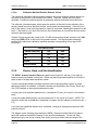
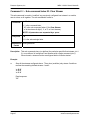
Cluster, Rack, and Slot Identification
The 98RK-1 Scanner Interface Rack can operate as a single unit, with one (1) to eight (8)
pressure scanners installed in each rack. Racks may also be grouped together as a cluster of
racks as part of a larger data acquisition system.
In order to physically identify individual scanners within a data acquisition system, a simple
addressing scheme is available. Individual scanners are identified by their Cluster, Rack, and
Slot (CRS) address, a three-digit hexadecimal number.
A cluster (the most significant address unit), is numbered 0-F (hex), for a total of 16 clusters of
racks.
A rack (the middle address digit), may be numbered 0-15, for a total of 16 racks. (NOTE: The
switch for setting the rack address is numbered in integers, but the address is returned in hex —
0-F.)
A slot (the least significant address unit), numbered 1 through 8, designates a particular 9816
pressure scanner.
The diagram on the following page depicts the 98RK-1 Scanner Interface Rack front pullout
panel with switches identified for setting Cluster and Rack addresses. Cluster and Rack
addresses may be set at any number (user option) as long as it falls within the range of the
Page 26
www.PressureSystems.com
Pressure Systems, Inc.
98RK-1 & 9816 User’s Manual©
switch settings. (Slot addresses are automatically set by their specific physical presence within
the rack.)
The cluster address is set via a slotted screwdriver-adjustable hexadecimal switch on the PC293 (Ethernet Controller board), located in the pull-out slide tray (front panel of the 98RK-1).
Cluster address settings are 0 through F (a total of 16). In the illustration, the hexadecimal
switch is annotated.
Figure 2.8
98RK-1 Front Pull-out Tray Diagram
Top and Front Views
Page 27
www.PressureSystems.com
Pressure Systems, Inc.
98RK-1 & 9816 User’s Manual©
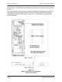
The rack address is set via a 16-position (0 through 15) push wheel switch, located on the front
panel of the 98RK-1.
The slot addresses are numbered 1 through 8, starting from the leftmost slot in the 98RK-1 and
each scanner’s address is fixed by its physical presence in the rack.
The following illustration shows how a typical CRS addressing system would identify a
particular scanner:
Figure 2.9
Typical Depiction of C-R-S Scanner Identification
In the above depicted array, the CRS address of the shaded scanner would be 133, cluster 1,
rack 3 and slot 3.
Page 28
www.PressureSystems.com
Pressure Systems, Inc.
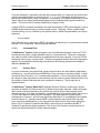
2.4
98RK-1 & 9816 User’s Manual©
Acquiring Data
STEP 20
From the Acquire menu, select “Acquire Data” to read the pressure of each channel
on the screen. The pressure is displayed both in engineering units and on the
individual bar graphs as a proportion of transducer full scale.
STEP 21
To log data, select “Log.” A file name will be requested with an automatic path to
the NUSS directory. Click “Cancel” to display the data on the screen. While
logging, the data is displayed on the logging screen in engineering units. To stop
logging, select “Stop.”
STEP 22
To stop data acquisition and freeze the display at the last reading, select “Stop
Acq.” from the “Acquire Data” menu.
STEP 23
Select Re-zero from the Calibration menu. This will perform a Re-zero calibration
and report the amount of offset which has automatically been corrected (relative to
the factory calibration stored within each transducer).
STEP 24
The temperature of each transducer can also be displayed in units of degrees
Celsius (ºC) by selecting Acq. Temp. Each transducer has an integral temperature
sensor used primarily for the digital temperature compensation which is performed
automatically.
Reading the temperature is most useful when verifying that you are operating within the
calibrated temperature range. The 9816 modules will update this value once every 15 seconds.
You have accomplished all of the steps in this manual for quickly getting a single NetScanner™
System module up, running, and acquiring data. To similarly test another module in the rack
(or externally attached), use the “Next Module” menu command.
Page 29
www.PressureSystems.com
Pressure Systems, Inc.
98RK-1 & 9816 User’s Manual©
Chapter 3
Programming and Operation
3.1
Commands & Responses
3.1.1
Introduction
This chapter describes all commands a host computer program may send to each of the
NetScanner™ System Intelligent Pressure Scanner modules (Model 9816) that are connected
to the various slots of the 98RK-1 Scanner Interface Rack chassis, as well as the data or
status responses returned by these modules. Some of the commands are similar to those for
other NetScanner™ System models (e.g., 903x, 9016/9116 or 9021/9022) that may be
externally attached to the 98RK-1 chassis. However, refer to their appropriate users’ manuals
since some commands are model-specific. Most applications require working knowledge of only
a small number of commands.
Each internal Model 9816 pressure scanner module (mounted in 98RK-1 chassis slots) has an
Ethernet interface and uses layered TCP/UDP/IP transmission protocols to communicate with a
host computer. These same protocols (and Ethernet interface) are also used for any externallyconnected scanner or standard/calibrator modules (connected to the 98RK-1 chassis rear
connectors). These modules are all “networked” together (with a host computer) via the 12-port
Ethernet gigabit switch (inside the 98RK-1 chassis).
All commands/responses to and from NetScanner™ System modules are embedded in the
data fields of either a TCP or UDP packet header. In turn, these packets are themselves
embedded in the data field of an IP packet header — which is embedded in the data field of an
Ethernet packet header. Thus, the term layered protocols.
3.1.2
TCP/UDP/IP Protocols
TCP/UDP/IP protocols are a well-established set of rules for communicating over a network
(LAN, intranet, or internet), and are independent of the network’s physical medium. The Model
9816 uses the TCP/IP protocols for most commands and responses since the TCP layer
provides a robust error detection and correction mechanism, but requires the establishment of a
formal connection between host and module. The simpler UDP layer, requiring no formal
connection, is utilized for a few simple commands and a query response.
Using the underlying basic IP protocol, the host computer and interconnected modules are all
“peers” that can all communicate equally. Each “peer” must have a unique “logical” IP Address
(as well as its own unique “physical” Ethernet Address) to be directly addressed. Any “peer”
may initiate transmissions without permission from the receiver. In NetScanner™ System
implementation, the host computer is normally a client and generally initiates most
Page 30
www.PressureSystems.com
Pressure Systems, Inc.
98RK-1 & 9816 User’s Manual©
transmissions by sending commands to the modules, which are normally servers. However, a
module can initiate its own transmissions in some operating modes (e.g., the hardwaretriggered or free-run autonomous host streams generated by the Configure/Control
Autonomous Host Streams ('c') command). A maximum of 255 modules are easily
addressed by varying only the low-order byte of a typical IP Address. Many more modules may
be addressed by also changing the “network” portion (high-order 3 bytes) of the IP address.
A “peer” may be directly addressed by its IP address (in xxx.xxx.xxx.xxx format) or by use of a
predefined logical name that allows its IP Address to be looked-up in the sender’s database or
in a central network server’s database. Windows®-based operating systems provide a simple
text file database called “Hosts.” Review the file “Hosts.sam” in the “C:\windows” directory.
Modify and rename it “Hosts.” (no file extension) to activate it.
Before the host computer and any module can communicate with the higher level TCP/IP
protocols, the host (client) must request a connection be established with the module (server).
Each module expects all such requests for connection to be requested by its IP Address, and
directed to “well-known” port 9000 (default). After the connection is made, a socket is
established as a logical handle to this connection. The host and module may then
communicate, via this socket, until it is closed (or is lost at either module or host end, due to
power failure or reboot). The host and module may also communicate in a limited fashion
without a connection, using the middle-level UDP/IP protocols. In that case, the host simply
broadcasts commands via port 7000, and each module (that chooses to respond) returns the
response on port 7001. Only a few commands use UDP/IP in NetScanner™ System modules.
3.1.3
Commands
The commands (and responses) used by all Model 9816 modules consist of short strings of
ASCII characters. The TCP/UDP/IP protocols allow for the transfer of either printable ASCII
characters or binary data. When using certain formats, internal binary data values are often
converted to ASCII-hex digit strings externally. Such values may include the ASCII number
characters ‘0’ through ‘9’, the uppercase ASCII characters ‘A’ through ‘F’, and the lowercase
ASCII characters ‘a’ through ‘f.’ These hex values may represent bit maps of individual options,
or actual internal integer or floating point (IEEE) binary data values. In other cases (see
optional format 7 below), binary data may be transmitted directly as 4-byte (32-bit) big-endian
binary values without any formatting change.
3.1.3.1
General Command Format
A typical TCP/IP command (contained in the data field following a TCP packet header) is a
variable-length character string with the following general fields:
●
●
●
a 1-character command letter (c),
an optional position field (ppppp), a variable length string of hexadecimal digits,
a variable number of optional datum fields (dddd): each a variable length string,
normally formatted as a decimal number (with a leading space character, and with or
without sign and/or decimal point, as needed).
Using brackets ([ ] ) to show optional elements, and ellipsis (...) to show indefinite repetition, a
typical TCP/IP command may be viewed schematically as follows:
“c[[[[[p]p]p]p]p][ dddd[ dddd]...]”
Page 31
www.PressureSystems.com
Pressure Systems, Inc.
98RK-1 & 9816 User’s Manual©
From this schematic, it should be clear that the command letter (c) is required, the position field
(ppppp) immediately follows it, and may have 0, 1, 2, 3, 4, or 5 characters, and there may be
zero or more datum fields ( dddd), as required. For simplicity, the variable length nature of each
"dddd" string is not shown [with brackets] above, but the required leading space character is
shown. The position field is similarly simplified (as “ppppp”) below.
A typical UDP/IP command (contained in the data field following a UDP packet header) is also a
variable length character string, but has a simpler format. Generally, it has a variable length
command string (cccccc), followed by one optional datum ( dddd) field (preceded by one space
character):
“cccccc[ dddd]”
Since there are only a few simple UDP/IP commands, all references to commands below should
assume TCP/IP commands, unless otherwise indicated.
3.1.3.2
Command Field
All NetScanner™ System models recognize a set of predefined commands. Most are TCP/IP
commands having only a single alphabetic letter for a command field. These are recognized
only when a formal socket connection is established with the host computer. A few are UDP/IP
commands with a longer command field. These are recognized anytime the module has power
applied. All commands are functionally summarized in the following sections and detailed in
reference Section 3.2.
3.1.3.3
Position Field
For some commands, the position field (ppppp) may be broken into other distinct independent
subfields (e.g., xxyyzzf) and these subfields may or may not relate to any datum fields. In other
commands, there may be a 1-to-1 correspondence between ‘1’ bits in the position field (viewed
as a binary bit map expressed as a hex number) and the number of datum fields that follow it (or
the number of datum fields returned in the command’s response). The bit map form is
explained below.
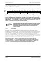
All NetScanner™ System (Model 9816) Intelligent Pressure Scanner models may contain a
maximum of sixteen (16) internal and two (2) external (rack) input channels. When commands
affect certain channels scanned by the module, the position field is used to identify those
channels as bits in a bit map. If a channel’s corresponding bit in the position field is set to a one
(1), then that channel is affected by the command. The least-significant (rightmost) bit 0
corresponds to Channel 1, and the most significant (leftmost) bit 15 corresponds to the highest
internal Channel 16. Special external (98RK-1 rack) channels, that a Model 9816 can also
scan, require two additional bits (in one more 4-bit hex digit in the bit map shown highlighted
below). Bit 16 (Channel S) specifies the 98RK-1 rack’s source air transducer and Bit 17
(Channel P) specifies the purge transducer. Bits 18 and 19 will remain unused (must be=0)
unless they become defined in a future software release.
Page 32
www.PressureSystems.com
Pressure Systems, Inc.
98RK-1 & 9816 User’s Manual©
In the following example 20-bit (5-hex digit) position field, internal channels 16 and 1, and both
external P & S pressures, are selected:
Bit#
19
18
Chan#
Binary
0
Hex
0
17
16
15
14
13
12
11
10
9
8
7
6
5
4
3
2
1
0
P
S
16
15
14
13
12
11
10
9
8
7
6
5
4
3
2
1
1
1
1
0
0
0
0
0
0
0
0
0
0
0
0
0
0
1
3
8
0
0
1
When all applicable internal channel bits are set in the position field (i.e., FFFF for a 16-channel
9816 module), it specifies all internal channels. Alternately, some commands allow a missing
position field to designate all internal channels, but only when there are no other parameters
following the position field in the command. Optionally, the hex position field may be reduced
from 5 to 4 digits when no external (P & S) channel bits need be set (=1) in the discarded highorder hex digit). In two commands ('C' and 'c'), only the position field may have 1-5 digits, as
needed, to specify progressively higher numbered channels.
Note
3.1.3.4
A position field bit map may specify the number and order of datum
data from module). In either case, the order of the datum fields is
from highest requested channel number to lowest requested
channel number.
Datum Fields
Any datum fields in a command generally contain data to be sent to the module, usually
specified by a position field bit map. In some commands (when data are to be received from a
module instead) no datum fields are required in the command itself, but the position field bit
map is still used to specify the order that data are returned in the command’s response. In
either case, the order bits are set (to 1) in the position field bit map (highest channel # to lowest
channel #, left to right) is the order these datum fields are received or sent. The special external
P & S channels are considered higher #’s than any internal channels #’s (16-1).
Each datum field may be variable in length, whether part of the command itself or the
command’s response. In its most common format, a datum begins with a space character
(‘ ’), and is followed by an optional sign, decimal digits, and decimal point, as needed (e.g., vv.vvvvvv). For other formats it may be a hex digit string or pure binary number.
Page 33
www.PressureSystems.com
Pressure Systems, Inc.
3.1.3.5
98RK-1 & 9816 User’s Manual©
Format Field
Some commands, that either send data to a module (as command parameters), or cause the
host to receive data (via command’s response), have an extra format parameter (f digit)
appended to (or specified in) the position field. This parameter, when specified (or implied by
default), governs how internal data are converted to/from external (user-visible) form.
●
The most common format (f=0) causes each datum (in command or response) to be a
decimal number externally (with optional sign and decimal point as needed). Internally,
the module sets/obtains each converted datum to/from a single binary (32-bit) IEEE
float.
●
Some formats (f=1, 2, 5) encode/decode the internal binary format to/from ASCII
hexadecimal external form. Some of these “hex dump” formats provide an external hex
bit map of the internal binary value (float or integer as appropriate). Format 5 may
encode/decode the internal float value to/from an intermediate scaled binary integer
(e.g., float value * 1000 into integer, then to/from a hex bit map).
●
Two special “binary dump” formats (f=7 and f=8) may be used by some commands to
accept/return binary data directly from/to the user’s command/response. Such values
are not user-readable in their external form, but provide highly compact storage without
any accuracy loss due to formatting. Use of these formats allows both the module and
host program to operate at their most efficient low overhead. Format 7 returns the most
significant byte first (i.e., big endian). Format 8 returns the least significant byte first
(i.e., little endian).
See the individual command descriptions for the formats a particular command recognizes.
3.1.4
Responses
Four (4) types of responses can be returned from a 9816 NetScanner™ System Intelligent
Pressure Scanner module:
●
●
●
●
an Error response,
an Acknowledge response,
an Acknowledge with Data response, or
a Network Query response.
The first three may be returned by TCP/IP commands, the latter from a UDP/IP command.
Page 34
www.PressureSystems.com
Pressure Systems, Inc.
98RK-1 & 9816 User’s Manual©
The error response consists of the letter ‘N’ (for NAK, or negative acknowledge), followed by a
2-digit hexadecimal error code. The following table lists the error codes that can be returned
from a 9816 NetScanner™ System module:
CODE
MEANING
00
(Unused)
01
Undefined Command Received
02
Unused (by TCP/IP)
03
Input Buffer Overrun
04
Invalid ASCII Character Received
05
Data Field Error
06
Unused (by TCP/IP)
07
Specified Limits Invalid
08
NetScanner error: invalid parameter
09
Insufficient source air to shift calibration valve
0A
Calibration valve not in requested position
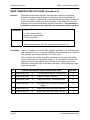
The Acknowledge response is returned from a module when a command is received that
requires no data to be returned, and no error is detected. It indicates successful parsing and
execution of the last received command. It consists of the letter ‘A’ (for ACK, or acknowledge).
The Acknowledge with Data response is returned when a module receives a command
requesting data. Model 9816 modules will typically return only the requested data values, each
preceded by a space character (except for format 7). No 'A' (acknowledge) letter begins this
data response. Data are returned for the highest requested channel number first. Data for
lower requested channels follow in reverse order (e.g., P&S, then 16-1).
3.1.4.1
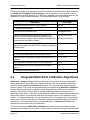
Interpreting Offset Values (Re-zero Calibration Adjustment)
When a Model 9816 module is instructed to execute the command Calculate and Set Offsets
('h'), a datum corresponding to the calculated offset correction term (or coefficient) is returned
for each affected channel. Each such coefficient value is stored internally, and will be
subtracted in all subsequently calculated data conversions, to correct for zero drift effects. The
command only returns them in the response (in current engineering units (EU) of pressure near
0.0) to allow the user to make reasonableness checks on them. The Read Internal
Coefficients ('u') command will return them on demand.
3.1.4.2
Interpreting Gain Values (Span Calibration Adjustment)
When a Model 9816 module is instructed to execute the command Calculate and Set Gains
('Z'), a datum corresponding to the calculated gain correction term (or coefficient) is returned
for each affected channel. Like the offset coefficient, each gain coefficient is stored internally,
and will be used in all subsequently calculated data conversions, to correct for gain change
effects. The command returns them in the response (as a unitless factor near 1.0) to allow the
Page 35
www.PressureSystems.com
Pressure Systems, Inc.
98RK-1 & 9816 User’s Manual©
user to make reasonableness checks on them. The Read Internal Coefficients ('u') command
will return them on demand.
3.1.4.3
Interpreting Engineering Units Output
All Model 9816 modules perform all internal pressure calculations in engineering units (EU) of
pounds per square inch (psi). By default, all pressure data in responses and command
parameters will also be in psi. A different engineering unit (e.g., kPa) may be obtained by
changing an internal EU Pressure Conversion Scaler (normally 1.0). See the
“Read/Download Internal Coefficients” ('u'/'v') commands (array 11, coefficient 01).
3.1.5
Functional Command Overview
The various NetScanner™ System commands for 9816 modules are best introduced by
classifying them into functional groups and then describing how each function is carried out in a
typical system. The following functions are defined for this purpose:
●
●
●
●
●
Start-up Initialization
Scan List Definition for Acquisition
Calibration Adjustment of Engineering Unit Correction Coefficients
Acquisition/Delivery of Data to Host
Network Query and Control
Please look ahead to Table 3.1, labeled 9816 NetScanner™ System Commands, in Section
3.2, for a quick-look summary of all commands available to the Model 9816 module. Each
command may be referenced by both its functional title and by its command id in the functional
discussion sub-sections below.
The Detailed Command Description Reference immediately follows the table in Section 3.2,
with each command description occupying a page (or more if necessary). Command
descriptions in this section (as in the table) are ordered first by type (TCP/IP then UDP/IP), then
by “command id” in ASCII order (UPPERCASE letters (A .. Z) first, then lowercase letters (a ..
z)).
3.1.5.1
Start-up Initialization
Since power supplies may be distributed widely across a network of modules and host
computer(s), it is not uncommon for modules (singly or together) and the host to lose power
independently. Thus, their power may be restored at different times. Start-up initialization for
every module must normally be performed when its power is restored, as each module enters
default states after power-up, which may not be the state the host computer had previously
been operating in. Any previous TCP/IP socket connection is also lost after power failure and
must be re-established between host and module before any TCP/IP commands can be
recognized by the module. These commands are generally used to detect that start-up
initialization has occurred (or to force reset at other times), after which other commands may be
used to restore the original operating condition.
In the NetScanner™ System (using the 98RK-1 Scanner Interface Rack), the Power-Up Clear
('A') command may be used as a simple command to elicit a known response from a module.
Although this causes no internal function within the module, it will result in an acknowledgment
being returned to the host computer to verify proper communications. The best way to detect
Page 36
www.PressureSystems.com
Pressure Systems, Inc.
98RK-1 & 9816 User’s Manual©
that a power reset has occurred in a module is to notice that the TCP/IP socket connection is no
longer valid. At any point during module operation, the Reset ('B') command may be used to
return any module to its default “reset” state. If the module is then required to enter any other
states (that were previously programmed for it by the host), the host must then restore these
states accordingly using the appropriate commands. This reset command simply returns
internal software parameters to a default state (as after power up or reboot). It will not close the
existing TCP/IP socket (as will power up or reboot).
The Set/Do Operating Options/Functions ('w') command has many purposes, but may first be
utilized during the module initialization stage. It may also be executed at any time during data
acquisition. However, some non-factory-default options of 'w' may become the new reset
default, if a particular function is used to establish them in non-volatile memory.
If any form of the Configure/Control Autonomous Host Streams ('c') command or the
Configure/Control Multi-Point Calibration ('C') command was in use before reset, it must be
executed again after the reset to restore it. Any other command, that establishes the module in
a non-default reset state, must be re-executed after a reset, if processing is to continue in that
state.
The Network Query (“psi9000”) UDP/IP command may be used (at any time) to make each
NetScanner™ System module on the network identify itself to the host(s). A parameter,
returned in each module’s response, indicates whether or not a module still has a valid
connection. This is a useful way to detect if an overt reset occurs in a module. The module
may be configured to emit this response automatically after any reset (power on or reboot).
3.1.5.2
Module Data Acquisition
After power-up, all NetScanner™ System modules will begin to scan all internal channels in
channel number order (16 to 1). Scanning will occur at the module's maximum internal rate
(using the previously stored number of data averages per channel). Special external rack (P &
S) channels of the 9816 module are also scanned, but less frequently. The data are stored in
an internal buffer, available for retrieval by the host computer. Engineering units conversion of
the scanned channels is accomplished (in a separate internal buffer) using thermal correction
data extracted from each transducer at power-up. While scanning, the module will
automatically monitor the attached transducers’ temperatures, correcting engineering unit output
for any temperature effects.
All NetScanner™ System models effectively defer the host computer’s decision of “which
channels of data do I want” until the host chooses to send read commands to actually retrieve
the desired data from the latest “buffered copy” of the continuously scanned, averaged, and
engineering-unit-converted data. See Section 3.1.5.4 (Delivery of Acquired Data to Host)
below for more details.
While scanning, all modules take multiple samples and average each channel. The number of
samples per internal channel defaults to 8 (eight), but may be set to 1 (one) to disable averaging
altogether, or set to any suitable higher value to change the degree of averaging (and its effect
on maximum scan rate). The Set Operating Options ('w') command may change this variable
at any time. The same command may be used to store the new averaging value as the
module’s reset default.
Page 37
www.PressureSystems.com
Pressure Systems, Inc.
3.1.5.3
98RK-1 & 9816 User’s Manual©
Calibration Adjustment of Offset/Gain Correction Coefficients
All NetScanner™ System Intelligent Pressure Scanners have built-in software commands (and
pneumatic hardware) to perform a periodic zero and span calibration adjustment of its internal
or attached pressure transducers. Use of these periodic adjustments result in the highest
possible data accuracy. The result of these calibrations is a new set of internal offset and gain
coefficients. These correction coefficients are over and above those factory-determined and
unchanging thermal correction coefficients stored in each transducer's non-volatile memory.
The factory coefficients provide basic engineering unit conversion capability, while also
correcting for various non-linear effects, including temperature effect compensation. The offset
and gain correction coefficients provide for fine “linear fit” adjustment of the factory calibration of
each transducer. If used properly, the periodic zero and span calibration adjustment
should be the only calibration required to maintain specified performance throughout the
life of the Intelligent Pressure Scanner.
It is generally necessary for the transducer to have real “zero” and “span” pressure points
(specified as 2 or more values) applied when calibration adjustment is required These pressure
values may be generated by secondary pressure standards, such as the Model 903x calibrator
module or by other external means provided by the customer (such as a dead weight calibrator).
For the more common zero-only calibration adjustment, zero differential pressures can typically
be provided without the need for external pressure generators. All 9816 models have built-in
pneumatic inputs (CAL side inputs) and calibration manifolds required for directing the
generated pressures to the various channels of the module(s) being calibrated. Refer to
Chapter 4 of this manual for detailed background and procedures for periodic calibration
of the Intelligent Pressure Scanners. A summary of the commands used for calibration
purposes is included below.
The Calculate and Set Offsets ('h') command is executed only when a suitable “minimum”
(e.g., zero) pressure has been applied to all channels of the module. The new offset
coefficients that result from execution of this command are stored in the module’s volatile (or
temporary) engineering-unit conversion database. They are also returned to the host in the
command’s response.
The Calculate and Set Gains ('Z') command should be executed only when “full-scale” (or
other suitable specified up-scale) pressure has been applied to the appropriate channels of a
module. The new gain coefficients that result from this command are stored in the module’s
volatile (or temporary) engineering-unit conversion database. They are also returned to the host
in the command’s response.
In modules using firmware version 2.24 or later, a Configure/Control Multi-Point Calibration
('C') command is provided. This command (actually 4 sub-commands) is an improvement over
the single calibration commands ('h' and 'Z') described above. Though 'C' provides for the
adjustment of the same offset and gain correction coefficients already described above, it does
so with two or more applied pressure calibration points. The final linear fit (i.e., new offset and
gain correction coefficients) is a “least squares” correction fit between all the calibration points
specified. This 'C' command is particularly useful in calibrating differential transducers over
their entire negative-to-positive range.
Although the calculated offset and gain correction coefficients simply remain in volatile memory
following execution of the calibration commands (for use by all subsequent EU conversions),
they may be optionally stored in non-volatile transducer memory with the Set Operating
Options ('w') command (Index 08 and 09).
Page 38
www.PressureSystems.com
Pressure Systems, Inc.
98RK-1 & 9816 User’s Manual©
The above correction coefficients are maintained internally in IEEE floating-point format. The
Read Internal Coefficients ('u') command and the Download Internal Coefficients ('v')
command can return (or manually set) calibration coefficients to the host in decimal or hex
dump formats in their responses.
3.1.5.4
Delivery of Acquired Data to Host
Several commands apply to host delivery of acquired data, either on demand or autonomously.
For all Ethernet models, the Read High Precision Data ('r') command may be used to obtain
high precision data (in various formats). In addition, Model 9816 provides several high speed,
high resolution output commands. The Read High-Speed Data ('b') command is used to read
“pure binary” engineering unit pressure (all 16 channels are returned in the lowest overhead
format). Use the 'r' and 'b' commands to get acquired data on demand.
The module can also deliver EU pressure data in streams, which consist of TCP/IP data packets
that arrive autonomously in the host (with data from selected channels being delivered in
various formats at various rates). Up to three independent streams (or time classes) may be
configured, started, stopped, and cleared with the Configure/Control Autonomous Host
Streams ('c') command. In conjunction with hardware triggering, this autonomous delivery
method can also make the module acquire (as well as deliver) data in its most efficient and
time-synchronized manner. This also frees the host to receive/process/record these data in its
most efficient manner, since it need not waste time continually requesting new data.
Model 9816 also has special purpose on demand data acquisition commands, including: Read
Transducer Voltages ('V') and Read Transducer Raw A/D Counts ('a'), which provide two
views of raw pressure data. It has similar commands providing EU temperature ( C) and other
raw views of each channel’s special temperature signal, including Read Transducer
Temperatures ('t'), Read Temperature A/D Counts ('m'), and Read Temperature Voltages
('n'). This command group is generally used for diagnostic purposes. All of these special
purpose data (plus other module status information) may also be periodically delivered to the
host automatically in any of the three flexible autonomous streams configured by the 'c'
command.
3.1.5.5
Network Query and Control Functions
A special subset of three (3) UDP/IP commands may be sent to a module at any time power is
applied to it (i.e., neither a host socket connection nor a unique IP Address assignment is
required). Each such command is broadcast to all modules (i.e., sent to IP Address
255.255.255.255) via Port 7000, and any module wishing to respond will return a response via
Port 7001.
Only one of these commands returns a response. This is the Network Query ('psi9000')
command. The others cause the module to be re-booted, therefore no response is possible.
One command changes the way the module gets its IP address assignment (i.e., dynamically
from a server or statically from factory-set internal data).
Page 39
www.PressureSystems.com
Pressure Systems, Inc.
3.1.5.6
98RK-1 & 9816 User’s Manual©
Other Functions
Some commands may be used at any time to obtain information about the internal setup and
status of a module. The Read Module Status ('q') command is an example. Also, the Set
Operating Options ('w') command, though generally used after power-up reset, may also be
used at other times as well to change system operation. The actual feedback position status of
internal valves, and several temperature status conditions, may be configured to be periodically
delivered to the host automatically in any of the three autonomous streams configured by the 'c'
command.
Page 40
www.PressureSystems.com
Pressure Systems, Inc.
3.2
98RK-1 & 9816 User’s Manual©
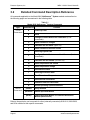
Detailed Command Description Reference
All commands applicable to the Model 9816 NetScanner™ System models are described on
the following pages and summarized in the following table.
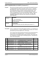
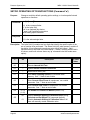
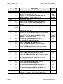
Table 3.1
Model 9816 NetScanner™ System Commands
type
command id
TCP/IP
Commands
A
Power-up Clear
B
Reset
C
Configure/Control Multi-Point Calibration (4 subcommands)
V
Read Transducer Voltages
Z
Calculate and Set Gains (Span Cal)
a
Read Transducer Raw A/D Counts
b
Read High Speed Data
c
Configure/Control Autonomous Host Streams (6 subcommands)
h
Calculate and Set Offsets (Re-zero Cal)
m
Read Temperature A/D Counts
n
Read Temperature Voltage
q
Read Module Status
r
Read High Precision Data
t
Read Transducer Temperature
u
Read Internal Coefficients
v
Download Internal Coefficients
w
Set/Do Operating Options/Functions
UDP/IP
Commands
psi9000
psireboot
psirarp
function
Query Network
Reboot Specified Module
Change Specified Module’s IP Address Resolution
Method (then Reboot)
Refer to the particular user’s manuals for other (externally connected) 9016/9116, 9021/9022,
and 903x models for their specific commands.
Page 41
www.PressureSystems.com
Pressure Systems, Inc.
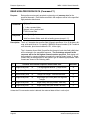
98RK-1 & 9816 User’s Manual©
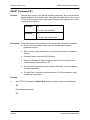
POWER UP CLEAR (Command 'A')
Purpose:
This command has no internal module affect. It is used as a simple
method to verify proper communications to the 9816 scanner.
Command
“A”
‘A’ is the command letter
Response
“A”
‘A’ is the acknowledge letter
Description: The Ethernet Model 9816 does not return a ‘Power-Up Clear Expected’ error (as
did early 901x modules without Ethernet interface). This is due to the reset
notification mechanisms that are part of the TCP/IP protocol. It is generally used
as a simple ‘NOP’ mechanism to verify proper communications with a module.
Example:
●
Send TCP/IP command to Model 9816 module (via its open socket) to acknowledge
module power on:
"A"
Read following response:
"A"
Page 42
www.PressureSystems.com
Pressure Systems, Inc.
98RK-1 & 9816 User’s Manual©
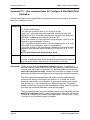
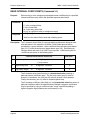
RESET (Command 'B')
Purpose:
Instructs the module to reset internal operating parameters, and to set all internal
control variables to their default “reset” state (see description below). The current
TCP/IP socket connection will remain open. Execution after a power off/on cycle
is optional (unnecessary).
Command
“B”
‘B’ is the command letter
Response
“A”
‘A’ is the acknowledge letter
Description: The module returns to the following “reset” states if this command is executed:
● Re-zero correction (offset) terms are set to the last values stored in
transducer memory.
●
Span correction (gain) terms are set to the last values stored in transducer
memory.
●
Calibration Valve is set to the RUN Position.
●
Number of Samples for Data Averaging is set to last value stored in nonvolatile memory (factory default = 8).
●
Any autonomous host data delivery streams defined by ‘c’ sub-commands
are reset (undefined).
●
The Multi-Point Calibration function defined by ‘C’ sub-commands is reset
(undefined) if in progress.
Example:
●
Send TCP/IP command to a Model 9816 module (via open socket) to reset defaults:
“B”
Read following response:
"A"
Page 43
www.PressureSystems.com
Pressure Systems, Inc.
98RK-1 & 9816 User’s Manual©
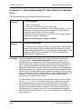
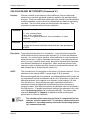
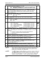
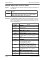
CONFIGURE/CONTROL MULTI-POINT CALIBRATION (Command 'C')
Purpose:
This command is actually four (4) sub-commands. The first configures and starts
a Multi-Point Calibration adjustment function for selected channels in the
module. Another is repeated multiple times to collect data for each defined
calibration point. Another ends the calibration function normally by calculating
new offset and gain adjustment coefficients from the collected data. It then
returns the module to its normal state, but with improved accuracy. A final subcommand is used only if it becomes necessary to abort the calibration function
while in progress. The general form of all sub-commands is described in the
table below. Subsequent pages separately describe each individual subcommand and give examples of each.
Note
Command
This 'C' command (with sub-commands) is available only in
modules that have upgraded to firmware Version 2.24 or later.
“C ii[ dddd]... ”
‘C’ is the command letter.
‘ ii’ is a required sub-command index preceded by a space character.
‘ dddd’ are zero or more optional datum (or parameter) fields, each
preceded by a space character. These vary with the sub-command used.
Response
Depends upon the particular sub-command (ii) used.
Description: The four 'C' sub-commands configure and control operation of a Multi-Point
Calibration function that is similar to the simpler re-zero and span calibration
adjustment functions (see separate 'h' and 'Z' commands). However, 'C' adjusts
both the offset and gain correction coefficients of each affected transducer at the
same time, using two or more calibration points. Thus, instead of simply
calculating a new linear (i.e., straight line) adjustment function that passes
through the supplied zero and span calibration points, it calculates a best-fit
straight line, using the least squares method, that comes “as close as
possible” to all the supplied calibration points. This correction method
provides the very best adjustment throughout the entire range (negative to
positive) of a differential transducer.
Note
Page 44
Avoid confusing this Calibrate command 'C' (upper case C) with the
Configure/Control Autonomous Host Streams command 'c' (lower
case c). Like 'c', but unlike most other module commands, all subcommands of this command require a space between the command
id ('C') and its first parameter (ii).
www.PressureSystems.com
Pressure Systems, Inc.
98RK-1 & 9816 User’s Manual©
Command 'C'— Sub-command Index 00: Configure & Start Multi-Point
Calibration
This sub-command has four (4) additional required parameters used to configure and start the
Multi-Point Calibration function.
Command
“C 00 pppp npts ord avg”
Response
‘C’ is the command letter.
‘ 00’ is the sub-command index (ii) for Configure & Start.
‘ pppp’ is a 1-4 hex digit position field (channel selection bit map), that
selects any of the 1-16 internal channels to be affected by the multi-point
calibration. It cannot specify external channels P & S.
‘ npts’ is the number of unique calibration points (between 1 and 19) to be
supplied during the calibration function.
‘ ord’ is the order of the adjustment fit, which currently must be 1 for a 1st
order linear fit of the calibration data (i.e., a straight line).
‘ avg’ is the number of A/D data samples collected and averaged for each
calibration point supplied (must be a power of 2 in the set 2, 4, 8, 16, 32,
or 64)
NOTE: all parameters are separated by a space.
“A”
‘A’ is the acknowledge letter and is returned if all parameters are supplied
with reasonable values. Else, an error (‘N’) response is returned.
Description: Configures and starts the Multi-Point Calibration function. It specifies the
particular channels (pppp) whose offset and span adjustment coefficients will be
replaced when the function is completed. All specified channels must have the
same full-scale pressure range. Modules with more than one range of internal
transducers installed must have channels from each range calibrated separately.
This sub-command immediately alters the module’s normal data acquisition
process’s A/D samples for average count (default = 8, or as per the ‘w10dd’
command) and uses the sub-command’s avg parameter sample count instead.
A larger count (e.g., 64) is encouraged for calibration purposes. The original
sample count will not be restored until the calibration function ends or is aborted
(per other sub-commands described on the following pages).
The npts parameter fixes how many calibration points must be supplied when the
Multi-Point Calibration function’s data collection phase starts later with multiple
invocations of another sub-command (described below). Currently, only a linear
(1st order) fit of the calibration points is available.
Page 45
www.PressureSystems.com
Pressure Systems, Inc.
98RK-1 & 9816 User’s Manual©
Example:
●
Configure and start the Multi-Point Calibration function so that it affects only the first
four (4) channels of the module. Three (3) pressure calibration points will by supplied
when we continue this function later (see example for ‘01’ sub-command below). A
linear (1st order) fit will be used to obtain a new set of offset and gain correction
coefficients for these four (4) channels. The maximum average sample count (64) is
used to collect each calibration data point, so as to minimize any noise in the data
samples. The module’s data acquisition process is altered immediately to collect the
increased number of averages.
“C 00 F 3 1 64”
Read response:
"A"
Page 46
www.PressureSystems.com
Pressure Systems, Inc.
98RK-1 & 9816 User’s Manual©
Command 'C'— Sub-command Index 01: Collect Data for a Calibration
Point
This sub-command has two (2) additional required parameters.
Command
“C 01 pnt pppp.pppp”
‘C’ is the command letter.
‘ 01’ is the sub-command index (ii) for Collect Data
‘ pnt’ identifies a particular calibration point that will be supplied. It must
be between 1 and npts, where npts was a parameter of the previously
executed Configure & Start (‘00’) sub-command.
‘ pppp.pppp’ is the pressure value (in current EU) that is actually applied
currently to the module’s transducers.
NOTE: all parameters are separated by a space.
Response
“pppp.pppp [pppp.pppp]...”
The actual measured pressure values (in current EU) from each affected
channel of the module (highest numbered specified channel first, lowest
numbered specified channel last, as per the pppp bit map parameter of the
Configure & Start (‘00’) sub-command. The decimal response datum
format (format 0) is always used.
Description: This sub-command (to be executed two or more times) carries out the data
collection phase of the Multi-Point Calibration function for exactly one (1)
calibration point (i.e., per parameter pnt). Each execution applies a specified
pressure value; then collects, averages, and stores the data for that calibration
point. It must be repeated until all pressure points, as specified by the npts
parameter of the original Configure & Start (‘00’) sub-command, are applied and
their data collected. For each particular point, enter the sub-command after that
point’s pressure value has been properly applied to the module, and that value is
stable (unchanging). Pressure may be applied to either the Cal or Run ports, as
necessary. Use a Model 903x Calibrator or some other suitable precision
pressure source to generate the pressure.
It is not necessary to enter the two or more calibration points in strict numerical
order (i.e., 1, 2, ... npts). Any convenient entry order is allowed, though each
point’s actual pressure value must be correctly stated (with the pppp.pppp
parameter) when executed. Previously entered points may be reentered if it is
necessary to account for hysteresis. However, all the points specified by the
pts parameter of the Configure & Start (‘00’) sub-command must be supplied
before the final Calculate and Apply (‘02’) sub-command can be executed, else
an error will result.
Page 47
www.PressureSystems.com
Pressure Systems, Inc.
98RK-1 & 9816 User’s Manual©
Example:
●
Supply each of the previously-specified three (3) pressure calibration points to the MultiPoint Calibration function, as was stated in the previous example of the Configure and
Start (‘00’) sub-command. Assume that all the affected four (4) channels have
differential transducers with the same -5 to +5 psi range. Include at least one pressure
point in the negative range of these transducers.
“C 01 1 -2.5”
“C 01 2 0.0”
“C 01 3 5.0”
Read responses (separately after each command executed above):
"-2.4998 -2.4999 -2.5001 -2.500"
"0.0 0.0013 -0.0133 -0.00001"
"5.0091 4.9992 5.0010 4.9998"
Data are returned in reverse channel number order (i.e., 4, 3, 2, 1) in each response.
Page 48
www.PressureSystems.com
Pressure Systems, Inc.
98RK-1 & 9816 User’s Manual©
Command 'C'- Sub-command Index 02: Calculate & Apply Correction
Coefficients
This sub-command has no additional parameters.
Command
“C 02”
‘C’ is the command letter.
‘ 02’ is the sub-command index (ii) for Calculate & Apply
NOTE: all parameters are separated by a space.
Response
“A”
‘A’ is the acknowledge letter — returned if the required number of
calibration data points had their data successfully collected previously, and
the resulting calculated data is reasonable. Else, an error (‘N’) response is
returned.
Description: This sub-command finishes the Multi-Point Calibration function, previously
started by the Configure & Start (‘00’) sub-command. It calculates new
correction coefficients using the pressure data collected by all required
executions of the Collect Data (‘01’) sub-command.
All the averaged data points collected previously are checked for
reasonableness, and then a new set of zero and gain correction coefficients are
calculated by the least-squares method for each channel (transducer) affected by
the calibration. These are stored in the module’s volatile memory for use by all
subsequent EU data conversion of these channels until the module is reset or
powered off. These coefficients may be stored in the non-volatile memory of the
module’s transducers with the 'w' command (see indexes 08 and 09 for that
command). The latest calculated zero and gain coefficients may be inspected
with the 'u' command at any time for any channel.
Finally, this sub-command restores the original “A/D samples for averaging”
count used by the module’s data acquisition process to the value that was in use
before the Multi-Point Calibration function was originally started.
Page 49
www.PressureSystems.com
Pressure Systems, Inc.
98RK-1 & 9816 User’s Manual©
Example:
●
Finish the Multi-Point Calibration function previously started (as indicated by the
previous examples of 'C' sub-commands ‘00’ and ‘01’). Calculate new adjustment
coefficients, and save them in the non-volatile memory of the module’s transducers.
These new coefficients will then be used for all subsequently calculated EU data
acquired by the module, until another calibration function is performed in the future.
“C 02”
“w08”
“w09”
Read responses (separately for each command executed above):
"A"
"A"
"A"
If an error (“N”) response is returned on the first command, either the correct number of
calibration points (per ‘00’ sub-command) were not supplied with reasonable pressure
data values (via the multiple ‘01’ sub-commands), or the collected data yielded new
calculated coefficients with unreasonable values.
If execution of the last two 'w' commands is skipped above, the new calibration data
obtained will be stored only in volatile storage, and will be available for use only until the
module is RESET or loses power.
Page 50
www.PressureSystems.com
Pressure Systems, Inc.
98RK-1 & 9816 User’s Manual©
Command 'C'— Sub-command Index 03: Abort Multi-Point Calibration
This sub-command has no additional parameters.
“C 03”
Command
‘C’ is the command letter.
‘ 03’ is the sub-command index (ii) for Abort.
NOTE: all parameters are separated by a space.
“A”
Response
‘A’ is the acknowledge letter
Description: Aborts the Multi-Point Calibration function, if it is currently in progress. This
sub-command also restores the original “A/D samples for averaging” count to the
module that was in use before the calibration function was started.
It should be noted that executing the Configure & Start (‘00’) sub-command
again, after the calibration function has started collecting data (per Collect Data
(‘01’) sub-commands), but before the final data are calculated (per Calculate &
Apply (‘02’) sub-command), will have the same affect as this Abort function.
Example:
●
Abort the Multi-Point Calibration function previously started
“C 03”
Read response:
"A"
Page 51
www.PressureSystems.com
Pressure Systems, Inc.
98RK-1 & 9816 User’s Manual©
READ TRANSDUCER VOLTAGES (Command 'V')
Purpose:
Command
Returns, for the specified channels, the most recently acquired raw pressure
data, converted to volts directly from the averaged A/D counts. This simple
engineering-unit conversion bypasses any usage of the transducer’s factorycalculated coefficients or the final calibration process’s correction coefficients
(offset and gain). Each datum returned in the response will be in the specified
high-precision data format. This command is intended for advanced users
only and is not required for normal operation.
“V[p]ppppf”
‘V’ is the command letter
‘[p]pppp’ is the position field
‘f’ is the format field
Response
“ dddd[ dddd]...”
‘ dddd’ are datum fields, each with a leading space (except f =7).
Description: The 4 or 5 character hex position field ([p]pppp) specifies a 16 or 20 bit binary bitmap, with each bit set to 1 to specify a particular channel number (S & P external
rack channels, plus internal channels 16-1, left-to-right).
The 1-character format field (f) specifies the format of each datum (‘ dddd’) that
will be returned in the requested response. The first datum returned in the
response will be for the highest channel number requested. Some formats may
not be applicable to the specific type of data being requested. Valid formats are
shown in the following table:
f
converts each internal response datum value from..
max.char.
0
single binary float
to
7-10-digit signed decimal “ [-xxx]x.xxxxxx”
13
1
single binary float
to
8-digit hex integer “ xxxxxxxx”
9
2
double binary float
to
16-digit hex integer “ xxxxxxxxxxxxxxxx”
17
5
single binary float
to
long integer (EU*1000) then to 8-digit hex
integer
9
7
single binary float
to
single binary float (big endian: msb first)
4
8
single binary float
to
single binary float (little endian: lsb first)
4
Page 52
www.PressureSystems.com
Pressure Systems, Inc.
98RK-1 & 9816 User’s Manual©
Example:
●
Send TCP/IP command to 9816 module (via its connected socket) that returns decimal
voltage data for internal channels 1, 5, 9, and 13:
“V11110”
Response contains data for channels 13, 9, 5, and 1 (left to right):
“ 4.999999 -4.989500 0.005390 2.500001”
●
Send TCP/IP command to 9816 module (via its connected socket) that returns decimal
voltage data for external S & P channels only:
“V300000”
Response contains data for channels S then P (left to right):
" 0.005880 1.500003"
Page 53
www.PressureSystems.com
Pressure Systems, Inc.
98RK-1 & 9816 User’s Manual©
CALCULATE AND SET GAINS (Command 'Z')
Purpose:
Command
Instructs a module to calculate new gain coefficients, with either full-scale
pressure (or a specified pressure) applied to the specified internal channels.
These new coefficients update part of the module’s internal calibration coefficient
database, used to convert any subsequent raw data (from any of the specified
channels) into engineering units data. The new gain values are also returned in
the response. This command is sometimes called a Gain calibration.
“Zpppp[ vv.vvvv]”
‘Z’ is the command letter
‘pppp’ is the position field
‘ vv.vvvv’ is an [optional] pressure value, preceded by a space character.
Response
“ g.gggg[ g.gggg]...”
‘g.gggg’ are the actual gain data values returned, each preceded by a
space.
Description: The position field may have 0 or 4 characters. If no position field is specified,
gain coefficients for all internal module channels (16-1) will be calculated and
returned. If a position field is specified, gain coefficients for only the channels
whose bits are set (=1) will be calculated and returned. If the optional pressure
value [ vv.vvvv] is specified, the position field must be 4 characters, even when
all channels are to be specified. Gain values are returned in the response in
order of highest specified channel to lowest specified channel, with data
formatted per an implied decimal format (f=0).
NOTE: This command may only be applied to the sixteen (16) internal channels.
It is not applicable for the external 98RK-1’s purge/supply (P & S) channels.
Normally this command requires that the exact full scale input pressure be
applied to the affected channels. The optional pressure value [ vv.vvvv] allows
the user to specify any suitable upscale pressure in the current engineering units.
For best results, pressures in excess of 90% of full scale should be applied. A
leading space character must precede the pressure value parameter. The
desired calibrating pressure must be applied to all of the specified channels (and
allowed to stabilize) before this command is executed. Such a pressure is
presumably generated by a separate Model 903x calibrator module or suitable
user-supplied substitute.
Internal 9816 firmware limits the allowed values for the calculated gain
coefficients between 0 and 100. If internal calculations result in gain coefficients
outside of this range, a default value of 1.00 will be used.
Notice that unlike the Calculate and Set Offsets (‘h’) command, this command
does not automatically move the module’s calibration valve to its CAL position. A
command to do this must precede this command. The reader is referred to
Chapter 4, Section 4.3 for additional details concerning the performance of a
Span Calibration.
Page 54
www.PressureSystems.com
Pressure Systems, Inc.
Note
98RK-1 & 9816 User’s Manual©
The calculated gain values from the latest 'Z' command will be
lost when the module is powered OFF. To save these gain
terms to each transducer's nonvolatile memory, refer to the Set
Operating Options ('w') command (index 09).
Example:
●
Send TCP/IP command to a 9816 module (via its open socket) to calculate and set gain
coefficients for channels 8 through 4. Instruct the module to use 14.8890 psi as the
applied pressure instead of each transducer’s full-scale value:
“Z00F8 14.8890”
Response:
" 1.01289 1.06953 1.03750 0.99704 1.10051"
Actual gain values are returned in the above response as decimal ASCII strings, each
preceded by a space character. From left-to-right: they are for channels 8, 7, 6, 5, and
4.
Page 55
www.PressureSystems.com
Pressure Systems, Inc.
98RK-1 & 9816 User’s Manual©
READ TRANSDUCER A/D COUNTS (Command 'a')
Purpose:
Command
Returns the most recently acquired raw pressure data for the specified channels
in averaged signed A/D counts (in the range -32768 to +32767). This simple
data bypasses any usage of the transducer’s factory-calculated coefficients or
the final calibration process’s correction coefficients (offset and gain). Each
datum returned in the response will be in the specified high-precision data
format, but representing A/D counts as a signed integer average. (The formula
for converting A/D Counts to volts is: Volts = A/D Counts * 5/32768.) This
command is intended for advanced users only and is not required for
normal operation.
“a[p]ppppf”
‘a’ is the command letter
‘ [p]pppp’ is the position field
‘f’ is the format field
Response
“ dddd[ dddd]...”
‘ dddd’ are datum fields, each with a leading space (except f =7).
Description: The 4 or 5 character hex position field ([p]pppp) specifies a 16 or 20 bit binary bitmap, with each bit set to 1 to specify a particular channel number (S & P external
rack channels, plus internal channels 16-1, left-to-right).
The 1-character format field (f) specifies the format of each data field (dddd) that
will be returned in the requested response. The first datum returned in the
response will be for the highest channel number requested. Some formats may
not be applicable to the specific type of data being requested. Valid formats are
shown in the following table:
f
converts each internal response datum value from..
max.char.
0
single binary float
to
7-10-digit signed decimal “ [-xxx]x.xxxxxx”
13
1
single binary float
to
8-digit hex integer “ xxxxxxxx”
9
2
double binary float
to
16-digit hex integer “ xxxxxxxxxxxxxxxx”
17
5
single binary float
to
long integer (EU*1000) then to 8-digit hex
integer
9
7
single binary float
to
single binary float (big endian: msb first)
4
8
single binary float
to
single binary float (little endian: lsb first)
4
Page 56
www.PressureSystems.com
Pressure Systems, Inc.
98RK-1 & 9816 User’s Manual©
Example:
●
Send TCP/IP command to 9816 module (via its connected socket) that returns decimal
raw “pressure” A/D counts data for internal channels 1, 5, 9, and 13:
“a11110”
Response contains data for channels 13, 9, 5, and 1 (left to right):
"32767.000000 -32700.000000 10.000000 16385.000000"
Please note that channel 13 is saturated at +full scale and channel 9 is almost saturated
at -full scale. Channel 5 reads near zero and channel 1 is about ½ +full-scale.
●
Send TCP/IP command to 9816 module (via its connected socket) that returns decimal
raw “pressure” A/D counts data for the external P & S channels only:
“a300000”
Response contains data for channels P then S (left to right):
"-10.000000 2.000000"
Note that both values are near zero counts (+ or -).
Page 57
www.PressureSystems.com
Pressure Systems, Inc.
98RK-1 & 9816 User’s Manual©
READ HIGH-SPEED DATA (Command 'b')
Purpose:
Command
Returns the most recent scanned and averaged data from all channels of the
module as fast as possible. Data is returned directly in its internal (IEEE singleprecision float) binary form (as per implied format 7). It is used as a faster
alternative to the Read High-Precision Data ('r') command, since 'b' does not
have to parse the position or format parameters, nor does it have to transform or
encode the internal data into any other format when the response is generated.
“b”
‘b’ is the command letter
Response
aaaabbbbcccc..rrrr
each 4-byte datum (e.g, ‘aaaa’) is a non-human readable 32-bit (4-byte)
big-endian binary value (format 7) representing an IEEE single-precision
internal float value.
Description: Returns data for all of the module’s external plus internal channels, in
order highest channel number to lowest channel number. Thus, the purge
(P) rack channel reading will always be the first 4-byte (32-bit binary, bigendian, IEEE floating-point) value (‘aaaa’) sent in the response. It is
followed by similar values (‘bbbb’, ‘cccc’, ... ‘rrrr’) for the source air (S)
rack channel, and then internal channels 16-1. Unless the EU conversion
scalar is altered, the returned data will be in units of psi.
Example:
●
Send TCP/IP command to a Model 9816 module (via its “socket” connection) to return
data as fast possible:
“b”
Data from the most recent scan of all the module’s channels are returned in pure binary
form, 4-bytes per channel (big endian):
aaaabbbbcccc .. rrrrpppp
Note that this response is not shown within quotes “ ” since it is not a valid ASCII
character string.
Page 58
www.PressureSystems.com
Pressure Systems, Inc.
98RK-1 & 9816 User’s Manual©
DEFINE/CONTROL AUTONOMOUS HOST STREAMS (Command 'c')
Purpose:
Defines and controls the autonomous delivery of any of up to three concurrent
high-speed data streams to the host computer. Such data streams may be
delivered “continuously” without bound (until a command explicitly stops them),
or be delivered in a “limited” amount (until a pre-specified fixed number of data
packets have been sent). Each packet delivered may be synchronized by a
“hardware trigger” or each packet may be delivered periodically as controlled by
an internal software clock. These concurrent host streams are an alternate
method of acquiring/delivering data rather than using the Read High-Precision
Data ('r') command or the Read High-Speed Data ('b') command.
Host data streams, once activated in a module, deliver a sequence of TCP/IP
data packets autonomously to the host (i.e., without host sending any particular
command to the module to request each packet). WARNING: If these data
streams are defined to occur at high rates, then each data packet received by the
host must be processed and disposed of in a timely manner.
Various sub-commands (described on the following pages) are used to identify
the various definition and control options of the following general 'c' command.
“c ii[ dddd]... ”
Command
‘c’ is the command letter.
‘ ii’ is a sub-command index (augment code) preceded by a space
character.
‘ dddd’ are one or more optional datum fields, each preceded by a space
character, which are parameters that differ per augment code ii.
NOTE: all parameters are separated by a space.
Response
Autonomous
Packet
Depends upon particular sub-command (ii) sent. See below.
Depends upon particular sub-command (ii) sent. See below.
Description: The firmware of a Model 9816 module, once fully initialized, continuously scans
and converts data for all internal pressure channels at the highest possible
speed. The result of such scanning is a continuously-updated EU data buffer,
available to three concurrent host data delivery tasks, or available to other
standard data acquisition commands of the module. Each host delivery task can
grab engineering-unit data values from the EU data buffer and deliver them to the
host in its own programmable data stream (a sequence of TCP/IP packets that
autonomously arrive in the host, as long as the host has enough TCP/IP
buffering space to hold them).
Special augments of this command (using the first parameter, ii) can configure
each data stream with the particular channels whose data are delivered, the
datum format, the delivery rate, and other characteristics. It can also start, stop,
or un-define a single stream or all defined streams.
Page 59
www.PressureSystems.com
Pressure Systems, Inc.
98RK-1 & 9816 User’s Manual©
The maximum rate of any one stream’s delivery is practically limited to the
maximum possible scan and data conversion rate of all the module’s channels.
Normally, these programmable host streams deliver host data at rates equal to or
slower than this natural cycle. For a typical application, the first stream delivers a
few channels, at a high rate (as defined by a hardware trigger). The second
stream delivers other channels at a medium rate (some multiple of the trigger
period), and the third stream can deliver still other channels at a slower rate (also
a multiple of the trigger period).
Note
Page 60
Avoid confusing this Configure/Control Autonomous Host Streams
command 'c' (lower case c) with the Configure/Control Multi-Point
Calibration command 'C' (upper case C). Like 'C', but unlike most
other module commands, all sub-commands of this command
require a space between the command id ('c') and the
first parameter (ii).
www.PressureSystems.com
Pressure Systems, Inc.
98RK-1 & 9816 User’s Manual©
Command 'c'— Sub-command Index 00: Configure a Host Delivery
Stream
This sub-command is used to configure the parameters of each of the three possible concurrent
host delivery streams, one at a time. Following this configuration phase, the stream (1, 2, or 3)
may be started and stopped with other sub-commands. The sub-command’s format is:
“c 00 st [[[[p]p]p]p]p sync per f num”
Command
‘c’ is the command letter.
‘ 00’ is the sub-command index (ii) for configuration.
‘ st’ is the stream id digit (1, 2, or 3).
‘ ppppp’ is a 1-5 digit hex position field (channel selection bit map),
capable of selecting 1-18 external/internal channels.
‘ sync’ is sync type (0=hardware trigger or 1=clock).
‘ per’ is the period (if sync=0: # of trigger periods or if sync=1: delay timer
period in msec).
‘ f’ is the format of each acquired datum in stream.
‘ num’ is the number of packets delivered in stream
(0=unlimited/continuous).
NOTE: all parameters are separated by a space.
“A”
Response
‘A’ is the acknowledge letter
Autonomous
Packet
none generated
Description: Configures a particular stream (‘st’) to deliver data packets autonomously to the
Configures a particular stream (st) to deliver data packets autonomously to the
host, with each packet containing selected acquired data for the channels
specified. These channels are specified by a bit map (4-20-bits) encoded as a 15 hex digit position field (ppppp as described in Section 3.1.3.3). A separate subcommand (ii=05) may be used to select which acquired data are included in each
stream. By default, only Pressure EU Data are selected (if ii=05 sub-command
never executed for stream).
The individual data packets of the stream may be synchronized with either an
external (user-supplied) hardware trigger or a periodic clock interrupt generated
inside each module. This choice is made with the sync type (sync) parameter (a
single digit) where: 0 = synchronize with hardware trigger; 1= synchronize with
periodic software clock.
When the hardware trigger is used to synchronize data output (sync = 0), it is
assumed that the user would prefer to also synchronize the internal data
acquisition cycle. For this reason, when a stream utilizing hardware trigger is
started, the module firmware switches out of the free-running continuous data
acquisition mode described earlier. Instead, the Model 9816 waits in an idle
mode until a hardware trigger is received to initiate a host stream output. Only
on the receipt of that hardware trigger will the module scan and EU convert all
Page 61
www.PressureSystems.com
Pressure Systems, Inc.
98RK-1 & 9816 User’s Manual©
internal channels. Following completion of the acquisition (and EU conversion)
cycle, the module will also deliver the requested data channels to the host. In
this manner, users are provided with highly synchronized data acquisition and
delivery from one or more modules. If a module waits in the idle mode for an
extended period of time without receiving a data request, it will periodically
initiate its own internal data acquisition cycles so as to update internal thermal
coefficients. When all hardware triggered streams are complete or aborted, an
individual module will return to the default mode of continuous scanning and EU
conversion.
When the internal software timer is used to control host stream output rates
(sync=1), note that the internal clock frequency variances will result in slightly
different timing between modules. Although these differences in timing are slight,
they may result in noticeable differences in output timing between modules over
a long period of time. If highly synchronized data output is required from multiple
modules, the hardware trigger mode should be used.
The period (per) parameter is a positive decimal integer count (from 0 to
2147483647, specified with 1 to 10 numeric characters as needed). Its meaning
(described in the following table) depends on the sync type (sync) parameter
described above.
sync
meaning of per
0
number of hardware trigger periods to wait before sending
each packet
1
delay period (in milliseconds) to wait between sending each
packet NOTE: minimum is 10 milliseconds
The f parameter identifies the format of each selected acquired datum in each stream packet,
and is a single numeric digit. Valid format codes are listed in the following table:
f
converts each internal selected acquired datum value from..
max.char.
0
single binary float
to
7-10-digit signed decimal “ [-xxx]x.xxxxxx”
13
1
single binary float
to
8-digit hex integer “ xxxxxxxx”
9
2
double binary float
to
16-digit hex integer “ xxxxxxxxxxxxxxxx”
17
5
single binary float
to
long integer (EU*1000) then to 8-digit hex
integer
9
7
single binary float
to
single binary float (big endian: msb first)
4
8
single binary float
to
single binary float (little endian: lsb first)
4
Unless the EU conversion scalar is altered, returned pressure data will be in units of psi. See
command 'v', array 11, coefficient 01 for other units.
Page 62
www.PressureSystems.com
Pressure Systems, Inc.
98RK-1 & 9816 User’s Manual©
NOTE: With the exception of binary format 7, all other formats include a leading space in each
datum delivered in each stream packet.
The number of stream packets (num) parameter is a positive integer count (specified with 1 to 5
numeric digits as needed). It sets a finite limit on the number of packets delivered in the host
data stream. The value 0 for this parameter requests “continuous” output packets for the
defined host stream (unbounded).
Example:
●
Configure three (3) separate autonomous host delivery streams, and divide the module’s
channels between them. Channels (1-4) must be delivered to host at a 10 Hz rate,
channels 5-8 may be delivered at half that rate, while the remaining channels 9-16 are
delivered at half the previous rate. All streams are generated continuously and
synchronized with the internal clock at 100 msec., 200 msec., and 400 msec. periods,
respectively. Data are requested in single precision binary IEEE float format (f = 7).
“c 00 1 000F 1 100 7 0”
“c 00 2 00F0 1 200 7 0”
“c 00 3 FF00 1 400 7 0”
Read responses:
“A”
“A”
“A”
To similarly acquire data at “relative” rates (1, 2, and 4) using a periodic hardware
trigger (assumed to also cycle at 10 Hz rate), enter the commands:
“c 00 1 000F 0 1 7 0”
“c 00 2 00F0 0 2 7 0”
“c 00 3 FF00 0 4 7 0”
Read responses:
"A"
"A"
"A"
Page 63
www.PressureSystems.com
Pressure Systems, Inc.
98RK-1 & 9816 User’s Manual©
Command 'c'— Sub-command Index 01: Start Stream
This sub-command is used to start the delivery of any previously configured host stream in a
module. If the stream started is of “continuous” duration, then it will be necessary to use the
Stop Stream sub-command later. Otherwise, the stream will end automatically if a finite number
of packets has been specified for it. This sub-command may also be used to resume a
previously stopped host stream that has not transmitted all requested data packets. The subcommand’s format is:
Command
“c 01 st”
‘c’ is the command letter.
‘ 01’ is the sub-command index (ii) for Start Stream.
‘ st’ is the stream id digit (1, 2, or 3, or 0=all streams).
NOTE: all parameters are separated by a space.
Response
“A”
‘A’ is the acknowledge letter
Autonomous
Packet
“tssss[ dddd[ dddd]...”
‘t’ is a 1-byte binary (8-bit) value identifying the stream number (1-3).
‘ssss’ is a 4-byte binary integer (32-bit, big endian) packet sequence
number.
‘ dddd’ are the selected acquired datum values in the selected format, plus
a leading space (except f=7).
Description: This sub-command starts a particular specified host stream (st=1-3); or starts all
configured host streams with a single command (st=0). Each autonomous host
stream packet begins with a 5-byte fixed-format (binary) data header (tssss).
The first byte (t) identifies the host stream, while a 32-bit unsigned binary
sequence number (ssss) completes the header. This sequence number will start
at one (1) for the first packet returned by a stream and increment for each other
returned packet of that stream. In the case of a “continuous” data stream, the
sequence number may overflow the maximum permissible 32-bit integer value. If
this occurs, the sequence number value will wrap around to zero (0) following the
largest 32-bit value (4294967295) and then continue to increment by one for
each returned packet. The sequence number field is intended to provide a
mechanism for host software to ensure that host data stream packets are
processed or stored in the order in which they were obtained by the 9816. Each
of the three possible host streams will report their own unique sequence number.
Note that if a previously stopped data stream is restarted, the returned sequence
numbers will resume with the next number at the point of the stream’s
termination. The sequence numbers will not restart at one if a scan list is
temporarily stopped and then restarted without reconfiguring the stream. A
“limited” stream will terminate once this sequence number equals the requested
number of packets for the stream.
Page 64
www.PressureSystems.com
Pressure Systems, Inc.
98RK-1 & 9816 User’s Manual©
For periodic hardware-triggered streams, that are never suspended and resumed
after being initially enabled, the sequence number may also serve as a “relative”
time stamp if the period (in milliseconds) of the hardware trigger is known.
If a special sub-command (ii=05) is used to select the content of a stream, other
status data may immediately follow the binary stream header and precede the
default Pressure EU Data (if selected). Still other special acquired data (per
selected channel) may follow the Pressure EU Data. The total of all groups of
selected acquired data in each packet will be ordered from highest channel
number requested to lowest channel number requested. Each such datum
(dddd) will be output per the format code specified when the stream was
configured (by sub-command 00).
Example:
●
Start all the streams configured in the previous example:
"c 01 0"
Read response:
"A"
Soon after the response is received, the requested data stream packets will begin
arriving in the host at a quantity, content, and rate determined by each stream’s own
particular current configuration (per both the 00 and 05 sub-commands).
Page 65
www.PressureSystems.com
Pressure Systems, Inc.
98RK-1 & 9816 User’s Manual©
Command 'c'— Sub-command Index 02: Stop Stream
This sub-command is used to abort (or temporarily suspend) the delivery of any previously
started host stream in a module, one at a time or all together, whether the stream was
“continuous” or “limited” duration. The sub-command’s format is:
“c 02 st”
Command
‘c’ is the command letter.
‘ 02’ is the sub-command index (ii) for Stop Stream.
‘ st’ is the stream id digit (1, 2, or 3, or 0=all streams).
NOTE: all parameters are separated by a space.
“A”
Response
‘A’ is the acknowledge letter
Autonomous
Packet
command stops generation of autonomous packets from the requested
stream(s).
Description: This sub-command stops the current “run” of a particular specified host stream
(st=1-3); or stops the current “run” of “all configured” host streams with a single
command (st=0).
The stopped stream may be resumed for any new “runs” with the Start Stream
sub-command, as long as that stream remains defined in the module. The Clear
Stream sub-command may be used to un-define a stream. Any stream must
first be reconfigured with the Configure A Host Delivery Stream sub-command
(00) to be fully restartable with the Start Stream sub-command (i.e., to start
again with sequence number = 1 for run’s first packet).
Example:
●
Stop all the streams configured in the previous example:
“c 02 0”
Read response:
"A"
Page 66
www.PressureSystems.com
Pressure Systems, Inc.
98RK-1 & 9816 User’s Manual©
Command 'c'— Sub-command Index 03: Clear Stream
This sub-command is used to “undefine” any previously configured host stream in a module,
one at a time, or all together. The sub-command’s format is:
Command
“c 03 st”
‘c’ is the command letter.
‘ 03’ is the sub-command index (ii) for Clear Stream.
‘ st’ is the stream id digit (1, 2, or 3, or 0=all streams).
NOTE: all parameters are separated by a space.
Response
“A”
‘A’ is the acknowledge letter.
Autonomous
Packet
none generated
Description: This sub-command clears (un-defines) the particular specified host stream (st=13); or un-defines “all configured” host streams with a single command (st=0).
Once cleared, a stream must be reconfigured before it can be started.
Example:
●
Stop all the streams configured above. Then clear (undefine) only stream 3 and then
resume the remaining defined streams 1 and 2:
“c 02 0”
“c 03 3”
“c 01 0”
Read response:
"A"
Page 67
www.PressureSystems.com
Pressure Systems, Inc.
98RK-1 & 9816 User’s Manual©
Command 'c' — Sub-command Index 04: Return Stream Information
This sub-command returns current stream configuration information in its response:
Command
"c 04 st"
‘c’ is the command letter.
‘ 04’ is the sub-command index (ii) for Return Info.
‘ st’ is the stream id digit (1, 2, or 3, =0 no allowed).
NOTE: all parameters are separated by a space.
Response
“st [[[[p]p]p]p]p sync per f num”
‘st’ is the stream identifier digit (1, 2, or 3).
‘ ppppp’ is a 1-5 hex digit position field (channel selection bit
map).
‘ sync’ is sync type character (0 or 1).
‘ per’ is the period (# trigger periods or delay timer period).
‘ f’ is the format of the data delivered in stream.
‘ num’ is the number of packets delivered in the stream.
NOTE: all datum fields are separated by a space.
Autonomous
Packet
none generated
Description: This sub-command returns current configuration information for a particular
stream. Returned values are defined the same as the sub-command parameters
of Configure a Host Delivery Stream (sub-command 00). Note that the ‘num’
field represents the number of packets returned so far (= last sequence number
returned, or =0 if stream not yet started).
Example:
●
Return scan list information for stream l
"c 04 1"
Read response:
"1 FFFF 0 20 7 32000"
Page 68
www.PressureSystems.com
Pressure Systems, Inc.
98RK-1 & 9816 User’s Manual©
Command 'c' — Sub-command Index 05: Select Data in a Stream
This sub-command sets options that cause a specified stream to deliver specific kinds of
information to host. By default, only Pressure EU Data are delivered.
Command
“c 05 st bbbb”
‘c’ is the command letter.
‘ 05’ is the sub-command index (ii) for Select Data.
‘ st’ is the stream id digit (1, 2, or 3, =0 no allowed).
‘ bbbb’ is the hex option field (bit map) to select which options will be
returned in the data stream. (See table)
Response
NOTE: all parameters are separated by a space.
"A"
‘A’ is the acknowledge letter.
Description: If this sub-command is never executed for a particular stream, then just
Pressure EU Data are delivered (by default) in that stream following the fixed
format binary header. However, this sub-command may also delete these
default pressure readings from a stream (by not specifying them) — as well as
add other selected acquired data to a stream (by specifying them).
The bit map values (shown in the following table) may be added together to
specify all the actual data groups that will be delivered in each packet of the
specified stream. The first two table entries, if their “bits” are specified, will
cause two-byte binary (16-bit, big endian) status values to be delivered in the
stream packet (immediately following the stream header). The third table entry, if
specified, will cause the Pressure EU Data to be delivered (next), per the
specified format (f), and for just the channels specified (P&S, then 16-1), in the
configured stream. The remaining table entries (*) will cause other special data
groups (i.e., raw pressures and EU temperature values, also in A/D counts or
voltage forms) to also be delivered in each stream packet. Each of these special
data groups is also output, if its “bit” is specified, in the order of its table entry
(within the packet). Each group will also have a datum per the specified
channels, and be in the specified format (per f).
Note
Page 69
Selecting too many other data groups will compromise
module performance.
www.PressureSystems.com
Pressure Systems, Inc.
98RK-1 & 9816 User’s Manual©
bbbb (hex)
data selected for inclusion in each stream packet
0001
Enable Valve Position Status (see next table)
0002
Enable DH Temperature Status (see bit map below)
0010
Enable Pressure EU Data (default if never executed)
0020
Enable Pressure A/D Counts*
0040
Enable Pressure Voltages*
0080
Enable DH Temperature EU Data (degrees C)*
0100
Enable DH Temperature A/D Counts*
0200
Enable DH Temperature Voltages*
Any Valve Position Status datum is delivered as a two-byte binary integer (16-bit, big endian)
with the following possible values (shown in hex below). If selected, this datum will follow the
stream header in each packet:
status (hex)
Valve Position Status
0000
Valves in RUN position
0001
Valves in CAL position
0010
Valves in LEAK/CHARGE position
0011
Valves in PURGE position
Any DH Temperature Status datum is delivered as a two-byte binary bit map (16-bit, big
endian) with each bit representing the status of DH #16 through DH #1 respectively. A bit value
of 0 (zero) indicates the DH is operating within its specified limits. A value of 1 (one) indicates
the DH is outside its specified limits.
Bit #
15
14
13
12
11
10
9
8
7
6
5
4
3
2
1
0
Chan #
16
15
14
13
12
11
10
9
8
7
6
5
4
3
2
1
Binary
1
0
0
0
0
0
0
0
0
0
0
0
0
0
0
1
Hex
8
0
0
1
The above example indicates that Channels 1 and 16 are operating outside the specified
temperature limits. This binary datum, when selected, follows the previous Valve Position
status datum (or the stream packet header).
Page 70
www.PressureSystems.com
Pressure Systems, Inc.
98RK-1 & 9816 User’s Manual©
Example:
●
Configure stream l to return both status fields, and all Pressure EU data
"c 05 1 0013"
Read response:
"A"
If or when stream 1 is subsequently enabled, data groups in that stream with the lowestbit-numbers (table positions) selected are delivered first. In this example (bbbb = 0013),
the Valve Position Status datum would be first, DH Temperature Status datum would
be second, and then all the specified Pressure EU data would follow last (highest
specified channel to lowest specified channel). Of course, the standard 5-byte binary
prefix (tssss) that begins all stream packets would precede all these data groups (see
the Autonomous Packet box in Start Stream sub-command (index 01).
Page 71
www.PressureSystems.com
Pressure Systems, Inc.
98RK-1 & 9816 User’s Manual©
Command 'c' — Sub-command Index 06: Select Protocol for Stream
Delivery
Command
“c 06 st pro [remport [ipaddr]]”
‘c’ is the command letter.
‘ 06’ is the sub-command index (ii) for Select Protocol.
‘ st’ is the stream id digit (0=the ONLY acceptable entry).
‘ pro’ is the protocol id digit (1=UDP/IP, 0=TCP/IP)
‘ remport’ is an optional remote port number to which each UDP
stream is directed in the host (port 9000 is the default if unspecified).
It is ignored if pro=0.
‘ ipaddr’ is an optional host IP address to which each UDP stream is
directed (default is the host IP address per current TCP connection
that sent this command). It is ignored if pro=0.
Response
NOTE: all parameters separated by a space.
"A"
‘A’ is the acknowledge letter.
Description:
This command sets the protocol by which every configured autonomous stream
is delivered to the host. It must be executed after streams are configured, but
before they are enabled.
By default, streams are delivered via the same TCP/IP protocol used to receive
commands from host (i.e., via the existing TCP/IP connection used to send this
command). However, for special circumstances, all autonomous streams may
be delivered to the host via the UDP/IP protocol instead. This command is
required only when UDP/IP is to be used. It also can restore the default protocol
(to TCP/IP) once it has been changed. The TCP/IP version of the command
ignores the optional (pro and ipaddr) parameters, which have meaning only to
the UDP/IP protocol.
Though the command has a stream parameter, it is currently limited to changing
the protocol of all defined streams at the same time (i.e., parameter st must be =
0, meaning all configured streams).
The optional remport parameter may be any value in the range 1024 to 65535.
However, remport = 7001 should be avoided, since NetScanner modules emit
UDP Query responses to that port, and most host programs should have a UDP
socket already bound to that port for receiving these special responses. The
choice of remport parameter will affect the way host software must handle
multiple modules sending streams. If every module uses the same port, then a
single host socket can be bound to that port to receive all responses from all
modules. The remote IP Address, given to that socket, at time of receipt of the
stream’s datagram, will identify the particular module who sent the datagram.
Page 72
www.PressureSystems.com
Pressure Systems, Inc.
98RK-1 & 9816 User’s Manual©
Alternately, every module may be given a unique remport number, requiring that
a host program bind a unique UDP socket to each of these unique remport
numbers. Then, when a particular socket receives a UDP datagram to its unique
port, the module sending it is automatically identified.
The optional ipaddr parameter is normally unspecified, causing it to default to use
the IP address of the current TCP/IP connection. That way the host need not
have to be aware of its own IP address. This parameter is provided in case a
special host has multiple network interfaces and wants to use more than one.
When used, ipaddr requires four dotted numeric fields (d.d.d.d). Each d is a 1-3
digit decimal number in the range 0-255. The ipaddr = 255.255.255.255 is best
avoided, unless the UDP datagrams of streams are to be broadcast to all
network nodes.
The ‘f’ parameter identifies the format of each selected acquired datum in each
stream packet, and is a single numeric digit. Valid format codes are listed in the
following table:
f
converts each internal selected acquired datum value from..
0
single binary float
to
7-10-digit signed decimal
max.char.
13
“ [-xxx]x.xxxxxx”
1
single binary float
to
8-digit hex integer “ xxxxxxxx”
9
2
double binary float
to
16-digit hex integer “ xxxxxxxxxxxxxxxx”
17
5
single binary float
to
long integer (EU*1000) then to 8-digit hex
integer
9
7
single binary float
to
single binary float (big endian: msb first)
4
8
single binary float
to
single binary float (little endian: lsb first)
4
Example:
●
Configure all streams to be delivered via UDP/IP protocol. Host expects the UDP
datagrams to arrive via port 7500. The IP Address of the current TCP/IP connection is
also used to send each UDP datagram.
"c 06 0 1 7500"
Read response:
"A"
●
Configure all streams to be delivered via the default TCP/IP protocol.
"c 06 0 0"
Read response:
"A"
Page 73
www.PressureSystems.com
Pressure Systems, Inc.
98RK-1 & 9816 User’s Manual©
CALCULATE AND SET OFFSETS (Command 'h')
Purpose:
Instructs a module to calculate new offset coefficients, with zero differential
pressure (or a specified “generated” pressure) applied to the specified internal
channels. These new coefficients update part of the module’s internal calibration
coefficient database, used to convert any subsequent raw data into engineering
units data. The new offset values are also returned in the response. This
command is sometimes called a Re-zero calibration.
Command
“hpppp[ vv.vvvv]”
‘h’ is the command letter
‘pppp’ is the position field
‘ vv.vvvv’ is an [optional] pressure value preceded by a space
character.
Response
“ g.gggg[ g.gggg]...”
‘ g.gggg’ are the actual offset data values returned, each preceded by
a space.
Description: The position field may have 0 or 4 characters. If no position field is specified,
offset coefficients for all internal module channels (16-1) will be calculated and
returned. If a position field is specified, offset coefficients for only the channels
whose bits are set (=1) will be calculated and returned. If the optional pressure
value [ vv.vvvv] is specified (rarely used), the position field must be 4 characters,
even when all channels are to be specified. Offset values are returned in the
response in order of highest specified channel to lowest specified channel, with
data formatted per an implied decimal format (f=0).
NOTE:
This command may only be applied to the sixteen (16) internal channels. It is not
applicable for the external 98RK-1’s purge/supply (P & S) channels.
Before acquiring data with this command, any addressed Model 9816 module will
normally attempt to place the calibration valve in the CAL position, so that a zero
differential pressure can be applied to all channels via the module’s CAL and
CAL Ref input port. Simply leaving these ports unattached will allow the
transducers to read the appropriate zero differential pressure if ambient air
pressure is stable. After data are acquired, the calibration valve will be placed in
the RUN position. To disable the automatic shifting of the calibration valve, refer
to the Set Operating Options ('w') command (index 0B). The reader is also
referred to Section 4.2 of Chapter 4 for additional details concerning the
performance of a Re-zero Calibration.
Note
Page 74
The calculated offset values from the latest 'h' command will be lost
when the module is powered off. To save these offset terms to each
transducer’s nonvolatile memory refer to the Set Operating Options
('w') command (index 08).
www.PressureSystems.com
Pressure Systems, Inc.
98RK-1 & 9816 User’s Manual©
Example:
●
Send TCP/IP command to a Model 9816 module (via its open socket) to calculate and
set new offset coefficients for channels 16 through 13.
“hF000”
Response:
" 0.0010 0.0020 0.0015 0.0025"
Actual offset values are returned in the above response as decimal ASCII strings, each
preceded by a space character. From left-to-right: they are for channels 16, 15, 14, and
13.
Page 75
www.PressureSystems.com
Pressure Systems, Inc.
98RK-1 & 9816 User’s Manual©
READ TEMPERATURE COUNTS (Command 'm')
Purpose:
Returns the most recently acquired raw temperature data for the specified
channels in averaged A/D counts (in the range -32768 to +32767). This
command is similar to command 'a', except that the raw data reflects a channel’s
temperature signal instead of its pressure signal. Each datum returned in the
response will be in the specified high-precision data format, but representing A/D
counts as a signed integer average. This command is intended for advanced
users only and is not required for normal operation.
Command
“m[p]ppppf”
‘m’ is the command letter
‘[p]pppp’ is the position field
‘f’ is the format field
Response
“ dddd[ dddd]...”
‘ dddd’ are datum fields, each with a leading space (except f =7).
Description: The 4 or 5 character hex position field ([p]pppp) specifies a 16 or 20 bit binary bitmap, with each bit set to 1 to specify a particular channel number (S & P external
rack channels, plus internal channels 16-1, left-to-right).
The 1-character format field (f) specifies the format of each data field (dddd) that
will be returned in the requested response. The first datum returned in the
response will be for the highest channel number supplied. Some formats may not
be applicable to the specific type of data being requested. Valid formats are
shown in the following table:
f
converts each internal response datum value from..
max.ch
ar.
0
single binary float
to
7-10-digit signed decimal “ [-xxx]x.xxxxxx”
13
1
single binary float
to
8-digit hex integer “ xxxxxxxx”
9
2
double binary float
to
16-digit hex integer “ xxxxxxxxxxxxxxxx”
17
5
single binary float
to
long integer (EU*1000) then to 8-digit hex
integer
9
7
single binary float
to
single binary float (big endian: msb first)
4
8
single binary float
to
single binary float (little endian: lsb first)
4
Page 76
www.PressureSystems.com
Pressure Systems, Inc.
98RK-1 & 9816 User’s Manual©
Example:
●
Send TCP/IP command to 9816 module (via its connected socket) that returns decimal
raw “temperature” A/D counts data for channels 1, 5, 9, and 13:
“m11110”
Response contains data for channels 13, 9, 5, and 1 (left to right):
" 32767.000000 -32700.000000 10.000000 16385.000000"
Please note that channel 13 is saturated at +full scale, channel 9 is almost saturated at –
full scale. Channel 5 reads near zero, and Channel 1 is about ½ +full-scale.
Page 77
www.PressureSystems.com
Pressure Systems, Inc.
98RK-1 & 9816 User’s Manual©
READ TEMPERATURE VOLTAGES (Command 'n')
Purpose:
Command
Returns the most recently acquired raw temperature data for the specified
channels converted to engineering-unit Volts directly from the averaged A/D
counts. It is similar to command 'V', except that the raw data reflects a channel’s
temperature signal instead of its pressure signals. Each datum returned in the
response will be in the specified high-precision data format. This command is
intended for advanced users only and is not required for normal operation.
“n[p]ppppf”
‘n’ is the command letter
‘[p]pppp’ is the position field
‘f’ is the format field
Response
“ dddd[ dddd]...”
‘ dddd’ are datum fields, each with a leading space (except f =7).
Description: The 4 or 5 character hex position field ([p]pppp) specifies a 16 or 20 bit binary bitmap, with each bit set to 1 to specify a particular channel number (S & P external
rack channels, plus internal channels 16-1, left-to-right).
The 1-character format field (f) specifies the format of each datum field (dddd)
that will be returned in the requested response. The first datum returned in the
response will be for the highest channel number. Some formats may not be
applicable to the specific type of data being requested. Valid formats are shown
in the following table:
f
converts each internal response datum value from..
max.char.
0
single binary float
to
7-10-digit signed decimal “ [-xxx]x.xxxxxx”
13
1
single binary float
to
8-digit hex integer “ xxxxxxxx”
9
2
double binary float
to
16-digit hex integer “ xxxxxxxxxxxxxxxx”
17
5
single binary float
to
long integer (EU*1000) then to 8-digit hex
integer
9
7
single binary float
to
single binary float (big endian: msb first)
4
8
single binary float
to
single binary float (little endian: lsb first)
4
Page 78
www.PressureSystems.com
Pressure Systems, Inc.
98RK-1 & 9816 User’s Manual©
Example:
●
Send TCP/IP command to 9816 module (via its connected socket) that returns decimal
Voltage data (of the raw temperature signal) for channels 1, 5, 9, and 13:
“n11110”
Response contains data for channels 13, 9, 5, and 1 (left to right):
"0.53013 0.541698 0.503633 0.000000"
In this example channels 13, 9, and 5 return normal temperature voltage signals in the
range of 0.5 to 0.6 volts. Note that channel 1 returns a value of 0.0 volts, indicating a
possible error in its temperature signal.
Page 79
www.PressureSystems.com
Pressure Systems, Inc.
98RK-1 & 9816 User’s Manual©
READ MODULE STATUS (Command 'q')
Purpose:
Returns requested module status information.
Command
“qii”
‘q’ is the command letter.
‘ii’ is the status index field.
“hhhh”
Response
‘hhhh’ is a 4-digit hex datum (or other (**) decimal datum).
Description: The 2-digit hex index field (ii) chooses a particular status field to be returned.
Returned value is described in following table for each index (a third column
shows any ‘w’ command index for setting same option):
ii
'w' set
index
returned value
4-digit hex or other decimal (**)
00
Module’s Model Number, as decimal (**) integer value (e.g., 9816).
01
Firmware Version, as hex value
(expressed internally as integer version * 100).
(e.g. hex ‘0100’ = 256 decimal, means Version 2.56)
02
Power-up Status, as 16-bit hex bit map, bits having the following meaning:
Bit 0 (LSB):
A/D Failure Error.
Bit 1:
Transducer Re-zero Adjustment (offset) Term Range Error (out-ofrange values set to 0.0 internally).
Bit 2:
Transducer Span Adjustment (gain) Term Range Error (out-of-range
values set to 1.0 internally).
Bit 3:
Temperature Correction Coefficients Not Present or Out-of-Range (if
transducer has one or more bad coefficients, all set to 0.0).
Bit 4:
reserved (for transducer checksum)
Bit 5:
FLASH Initialized Data Section Checksum Error (if error, all data
variables set to factory defaults and stored in FLASH).
Bit 6:
SRAM Error.
Bit 7:
Error Reading External DHs.
03
reserved
04
reserved
05
Number of A/D Samples To Average, as hex value (e.g., 000A=10 decimal).
Page 80
10
www.PressureSystems.com
Pressure Systems, Inc.
98RK-1 & 9816 User’s Manual©
06
IP Address Resolution Method, as hex state:
0000 = Use Static IP Address stored in module’s non-volatile memory
0001 = Get Dynamic IP Address from external RARP/BOOTP server
13
07
TCP Back-Off Delay, as hex value (or FFFF). FFFF means use low-order
byte of module’s Ethernet Address as value instead. In either case, back-off
delay in microseconds is calculated from decimal equivalent of hex value:
delay = decvalue * 20
14
08
TCP/IP Data Field Size Prefix (with 2-byte big-endian binary value),
as hex state: 0000 = None (default)
0001 = Yes
16
09
TCP Connect Port, as hex value (e.g. 2328 = 9000 decimal, default).
17
0A
Auto UDP Broadcast@Reset, as hex state:
0000 = No (default)
0001 = Yes
18
0B
Position of 4-state Internal Calibration Valves (C1/C2, C3/C4), as hex state:
0000 = RUN position
(C2/C4 Energized, C1/C3 Not)
0001 = CAL/RE-ZERO position
(C1/C4 Energized, C2/C3 Not)
0010 = LEAK/CHARGE position
(C2/C3 Energized, C1/C4 Not)
0011 = PURGE position
(C1/C3 Energized, C2/C4 Not)
(see end-of-table NOTE +)
(see also Chart at end of 'w' command)
0C
Temperature Status of Each Scanner Transducer, as 16-bit hex bit map,
each bit representing the current status of a transducer/channel (16-1)). Bit
values are:
0= transducer operating within the specified operational limits.
1= transducer operating outside the specified limits.
(see end-of-table NOTE +)
0D
Minimum Temperature Alarm Set Point (in degrees C), as decimal (**)
format 0 representation of internal IEEE float, with leading space).
19
0E
Maximum Temperature Alarm Set Point (in degrees C), as decimal (**)
format 0 representation of internal IEEE float, with leading space).
19
0F
Cluster (C), Rack (R), and Slot (S) Address, each item encoded as a hex
digit (most significant digit always zero): 0CRS
(see end-of-table NOTE ++)
10
External DH Scan Interval (in seconds) as decimal (**) integer value.
1A
11
Thermal Update Scan Interval (in seconds) as decimal (**) integer value.
1B
12/0C
00/00
00/01
01/00
01/01
(+)NOTE:
These 4-byte hex status fields may also be returned in autonomous data
streams, but as pure binary extensions of each stream packet’s binary
header (see ‘c’ command, ii=05, bbbb=0002).
(++)NOTE:
The 98RK-1 Scanner Interface Rack can operate as a single unit with up to
eight Model 9816 pressure scanners installed in slots of each rack. Racks
may also be grouped together in clusters of racks as part of a larger data
acquisition system installation. In order to physically identify individual
Page 81
www.PressureSystems.com
Pressure Systems, Inc.
98RK-1 & 9816 User’s Manual©
scanners within such a larger system, a simple three part addressing scheme
is available. Individual scanners are identified by their Cluster, Rack, and
Slot (CRS) address, a three-digit hexadecimal number.
A cluster (the most significant address unit), is numbered 0-F (0-15 decimal)
for a total of 16 clusters (clusters often refer to other geographical units like
control rooms or test stands).
A rack (the middle address digit), is numbered 0-F (0-15 decimal) for a total
of 16 racks per cluster. (NOTE: The 98RK-1 front-panel switch for setting the
rack address is labeled 0-15 decimal instead of hex 0-F)
A slot (the least significant address digit), numbered 1 through 8, designates
a particular 9816 pressure scanner in a rack.
Example:
Request model number from any NetScanner™ System module:
●
“q00”
Read response indicating a Model 9816:
"9816"
●
Request TCP back-off delay for any NetScanner™ System module:
“q07”
Read hex (16-bit binary) response:
"001F" (31 decimal, or 31*20= 620 µsec.)
Page 82
www.PressureSystems.com
Pressure Systems, Inc.
98RK-1 & 9816 User’s Manual©
READ HIGH-PRECISION DATA (Command 'r')
Purpose:
Command
Returns the most recently acquired engineering-unit pressure data for the
specified channels. Each datum returned in the response will be in the specified
high-precision data format.
“r[p]ppppf”
‘r’ is the command letter
‘[p]pppp’ is the position field
‘f’ is the format field
Response
“ dddd[ dddd]...”
‘ dddd’ are datum fields, each with a leading space (except f =7).
Description: The 4 or 5 character hex position field ([p]pppp) specifies a 16 or 20 bit binary bitmap, with each bit set to 1 to specify a particular channel number (S & P external
rack channels, plus internal channels 16-1, left-to-right).
The 1-character format field (f) specifies the format of each data field (dddd) that
will be returned in the requested response. The first datum returned in the
response will be for the highest channel number specified. Each datum will
be preceded by a space character (except in the case of binary format 7). Some
formats may not be applicable to the specific type of data being requested. Valid
formats are shown in the following table:
f
converts each internal response datum value from
max.char.
0
single binary float
to
7-10-digit signed decimal “ [-xxx]x.xxxxxx”
13
1
single binary float
to
8-digit hex integer “ xxxxxxxx”
9
2
double binary float
to
16-digit hex integer “ xxxxxxxxxxxxxxxx”
17
5
single binary float
to
long integer (EU*1000) then to 8-digit hex
integer
9
7
single binary float
to
single binary float (big endian: msb first)
4
8
single binary float
to
single binary float (little endian: lsb first)
4
Unless the EU conversion scalar is altered, the returned data will be in units of psi.
Page 83
www.PressureSystems.com
Pressure Systems, Inc.
98RK-1 & 9816 User’s Manual©
Example:
●
Send TCP/IP command to 9816 module (via its connected socket), that returns decimal
pressure data for channels 1, 5, 9, and 13 in ASCII fixed point format.
“r11110”
Response contains data for channels 13, 9, 5, and 1 (left to right):
"1.234000 0.989500 1.005390 0.899602"
Page 84
www.PressureSystems.com
Pressure Systems, Inc.
98RK-1 & 9816 User’s Manual©
READ TRANSDUCER TEMPERATURE (Command 't')
Purpose:
Returns the most recently acquired engineering-unit temperature data (in ºC) for
the specified channels. Each datum returned in the response will be in the
specified high-precision data format.
“t[p]ppppf”
Command
‘t’ is the command letter
‘[p]pppp’ is the position field
‘f’ is the format field
“ dddd[ dddd]...”
Response
‘ dddd’ are datum fields, each with a leading space (except f =7).
Description:
The 4 or 5 character hex position field ([p]pppp) specifies a 16 or 20 bit
binary bit-map, with each bit set to 1 to specify a particular channel
number (S & P external rack channels, plus internal channels 16-1, leftto-right).
The 1-character format field (f) specifies the format of each data field
(dddd) that will be returned in the requested response. The first datum
returned in the response will be for the highest channel number
specified. Each datum will be preceded by a space character. Some
formats may not be applicable to the specific type of data being
requested. Valid formats are shown in the following table:
f
Converts each internal response datum value from..
max.char.
0
single binary float
to
7-10-digit signed decimal “ [-xxx]x.xxxxxx”
13
1
single binary float
to
8-digit hex integer “ xxxxxxxx”
9
2
double binary float
to
16-digit hex integer “ xxxxxxxxxxxxxxxx”
17
5
single binary float
to
long integer (EU*1000) then to 8-digit hex
integer
9
7
single binary float
to
single binary float (big endian: msb first)
4
8
single binary float
to
single binary float (little endian: lsb first)
4
Example:
●
Send TCP/IP command to 9816 module (via its connected socket) that returns decimal
temperature data for channels 1, 5, 9, and 13:
“t11110”
Response contains data (in
C) for channels 13, 9, 5, and 1 (left to right):
"21.234000 20.989500 21.005390 20.899602"
Page 85
www.PressureSystems.com
Pressure Systems, Inc.
98RK-1 & 9816 User’s Manual©
READ INTERNAL COEFFICIENTS (Command 'u')
Purpose:
Command
Returns one (or more contiguous) requested internal coefficient(s) in a specified
internal coefficient array, and in the specified response data format.
“ufaacc[-cc]”
‘u’ is the command letter.
‘f’ is the format field.
‘aa’ is the array index field.
‘cc[-cc]’ is coefficient index [or contiguous range].
Response
dddd[ dddd]...”
‘ dddd’ are the datum fields, each with a leading space.
Description: The 1-character format field (f) is a single digit that defines the format of each
returned datum in the response. All datum ( dddd) fields returned will be
preceded by a space character. Most coefficients have a floating point datum
type (f=0-1), while others have an integer datum type (f=5). Requesting an
improper format will result in an “N08” error response. Valid format types for
coefficients are shown in the following table:
f
0
Converts each internal value from..
single binary float
to
7-10 digit signed decimal
max.char.
13
“ [-xxx]x.xxxxxx”
1
single binary float
to
8-digit hex “ xxxxxxxx”
9
5
long binary integer
to
8-digit hex “ xxxxxxxx”
9
The 2-character array index field (aa) is a hexadecimal value selecting a
particular internal coefficient array. The first array index (aa=01) refers to
channel 1's transducer, the 16th (aa=10) refers to channel 16's transducer.
Finally, the last array (aa=11) refers to a special global array.
The 2-character coefficient index field (cc) is a hexadecimal value that selects a
particular coefficient within the specified array. Multiple contiguous coefficients
may be specified by using a coefficient index “range” specified by adding a
hyphen (negative sign) between two such indexes (cc-cc).
Page 86
www.PressureSystems.com
Pressure Systems, Inc.
98RK-1 & 9816 User’s Manual©
Internal DH200 Transducer Coefficient arrays for internal channels 1-16 are selected with
array indexes aa=01 through aa=10 (hex). All valid coefficient indexes (for each of these
arrays) are listed in the following table:
cc
Page 87
Transducer Coefficient Description
Datum Type
00
Re-zero Cal Adjustment (offset) term
FLOAT
01
Span Cal Adjustment (gain) term
FLOAT
02
Dynamic EU Conversion coefficient c0
FLOAT
03
Dynamic EU Conversion coefficient c1
FLOAT
04
Dynamic EU Conversion coefficient c2
FLOAT
05
Dynamic EU Conversion coefficient c3
FLOAT
06
Dynamic EU Conversion coefficient c4
FLOAT
07
User Defined Date field (see end-of-table note)
INTEGER
08
Date of Factory Calibration (see end-of-table note)
INTEGER
09
Transducer Manufacturing Reference number
INTEGER
0A
Transducer Full-Scale Range code (see Appendix I)
INTEGER
0B
Temperature 1 Pressure 1 voltage
FLOAT
0C
Temperature 1 Pressure 2 voltage
FLOAT
0D
Temperature 1 Pressure 3 voltage
FLOAT
0E
Temperature 1 Pressure 4 voltage
FLOAT
0F
Temperature 1 Pressure 5 voltage
FLOAT
10-14
Temperature 2, Pressures 1-5 voltages
FLOAT
15-19
Temperature 3, Pressures 1-5 voltages
FLOAT
1A-1E
Temperature 4, Pressures 1-5 voltages
FLOAT
1F-23
Temperature 5, Pressures 1-5 voltages
FLOAT
24-28
Temperature 6, Pressures 1-5 voltages
FLOAT
29-2D
reserved for future use (temperature 7)
FLOAT
2E
Temperature 1 Temperature Output voltage at 0 psi
FLOAT
2F
Temperature 2 Temperature Output voltage at 0 psi
FLOAT
30
Temperature 3 Temperature Output voltage at 0 psi
FLOAT
31
Temperature 4 Temperature Output voltage at 0 psi
FLOAT
32
Temperature 5 Temperature Output voltage at 0 psi
FLOAT
33
Temperature 6 Temperature Output voltage at 0 psi
FLOAT
www.PressureSystems.com
Pressure Systems, Inc.
cc
98RK-1 & 9816 User’s Manual©
Transducer Coefficient Description
Datum Type
34
(reserved) Temperature 7 Temperature Output
voltage at 0 psi
FLOAT
35
Temp Vs Pressure Correction coefficient (t0)
FLOAT
36
Temp Vs Pressure Correction coefficient (t1)
FLOAT
37
Temp Vs Pressure Correction coefficient (t2)
FLOAT
38
Temp Vs Pressure Correction coefficient (t3)
FLOAT
The Date of Factory Calibration field (cc = 08) identifies the date of factory
calibration for the DH200 transducer. It is stored internally as a 32-bit integer
whose value is in the format of yymmdd (year, month, day).
NOTES:
The User Defined Date field (cc = 07) is a 32-bit integer which is encoded in a
similar manner. Possible uses are to indicate the date of last user zero and/or
span calibration or possibly the date of next required calibration. If this
optional field is used, the user is responsible for correctly encoding the date
into the proper 32-bit integer value. Any modifications of this field (using the
Download Internal Coefficients (‘v’) command) will result in the new value
automatically being entered to transducer’s nonvolatile memory.
A special single Other Coefficients array is selected with array index aa = 11 (hex). All the
valid coefficient indexes (for this array only) are listed in the following table:
cc
Page 88
Other Coefficients Description
Datum Type
00
reserved - EU Conversion Offset term
FLOAT
01
EU Pressure Conversion Scaler (default = 1.0)
FLOAT
02
reserved - EU Conversion Non-Linearity term
FLOAT
03
Module Reference Voltage value
FLOAT
04
Reserved for factory use
FLOAT
05
Reserved for factory use
FLOAT
06
Reserved for factory use
FLOAT
07
Reserved for factory use
FLOAT
08
9816 External DH Amplifier Zero Offset
FLOAT
09
9816 External DH Amplifier Span Adjustment
FLOAT
www.PressureSystems.com
Pressure Systems, Inc.
98RK-1 & 9816 User’s Manual©
Example:
●
Send TCP/IP command to 9816 module (via its connected socket) requesting the most
recent calibration adjustment’s offset and gain terms (cc=00-01), and the adjacent
factory-determined transducer coefficients C0 through C4 (cc=02-06): for transducer 1:
Data requested in ASCII-hex format representing the internal binary floating point format
"u10100-06"
Response returned is:
"3B200A6E . . 00000000"
Note
Page 89
The maximum response size is 300 characters. If the requested
range of coefficients requested exceeds this, the 9816 will return an
“N07” error response.
www.PressureSystems.com
Pressure Systems, Inc.
98RK-1 & 9816 User’s Manual©
DOWNLOAD INTERNAL COEFFICIENTS (Command 'v')
Purpose:
Downloads one or more internal coefficients to the module.
Command
“vfaacc[-cc] dddd[ dddd]...”
‘v’ is the command letter.
‘f’ is the format field.
‘aa’ is the array index field.
‘cc[-cc]’ is coefficient index [or contiguous range].
‘ dddd’ are the datum fields, each with a leading space.
Response
“A”
‘A’ is the acknowledge letter.
Description: The 1-character format field (f) is a single digit that defines the format of each
coefficient to be downloaded in the command’s datum ( dddd) fields, with each
datum preceded by a space character. Most coefficients have a floating point
datum type (f=0-1), while others have an integer datum type (f=5). Sending a
datum in the improper format will result in an “N08” error response. Valid format
types are shown in the following table:
f
converts each datum parameter value (‘ dddd’) from..
max.char.
0
1-10 digit signed decimal “ [-xxx]x.[xxxxxx]”
to single
binary float
13
1
8-digit hex “ xxxxxxxx”
to single
binary float
9
5
8-digit hex “ xxxxxxxx”
to long binary
integer
9
The 2-character array index field (aa) is a hexadecimal value selecting a
particular internal coefficient array to receive the downloaded data. The first
array index (aa=01) refers to channel 1's transducer, the 16th (aa=10) refers to
channel 16's transducer. Finally, the last array (aa=11) refers to a special global
array.
A 2-character coefficient index field (cc) is a hexadecimal value that selects a
particular coefficient within the specified array. Multiple contiguous coefficients
may be specified by using a coefficient index “range” specified by adding a
hyphen (negative sign) between two such indexes (cc-cc).
Transducer Coefficient arrays for internal channels 1-16 are selected with
array indexes aa=01 through aa=10 (hex). A special single Other Coefficient
array is selected with array index aa=11 (hex). All the valid coefficient (cc)
indexes (for each of these arrays) are listed in the appropriate tables included in
the description of the previous Read Internal Coefficients ('u') command.
Page 90
www.PressureSystems.com
Pressure Systems, Inc.
98RK-1 & 9816 User’s Manual©
Example:
●
Send TCP/IP command to 9816 module (i.e., via its connected socket) with replacement
values for the channel’s offset and gain correction terms loaded into the module’s
volatile memory (cc = 00-01). Load these into channel # 8's Transducer Coefficient
array (aa=08):
“v00800-01 0.000 1.000”
Response returned is:
"A"
●
Send command to 9816 module (via its connected socket) to change its default EU
output from psi to kPa. This will be done by changing the EU Pressure Conversion
Scaler to 6.894757.
"V01101 6.894757"
Response returned is
"A"
Page 91
www.PressureSystems.com
Pressure Systems, Inc.
98RK-1 & 9816 User’s Manual©
SET/DO OPERATING OPTIONS/FUNCTIONS (Command 'w')
Purpose:
Command
Change a module’s default operating option settings, or invoke special internal
operations or functions.
“wii[dd[ eeee]]”
‘w’ is the command letter.
‘ii’ is the index field.
‘dd’ is an [optional] hex datum.
‘ eeee’ is an [optional] extra datum
with leading space character.
“A”
Response
‘A’ is the acknowledge letter.
Description: The index field (ii) contains two hex digits that identify the specific option to be
set or function to be performed. The datum field (dd), when present, contains 2
hex digits. A few indexes also require an extra datum field (eeee). Valid
options/functions are listed in the table below (-- marks a missing datum field in
its column, and fourth column shows any 'q' command index that reads same
option):
ii
dd
00
--
Execute Internal Self Test.
01
--
Update Internal Thermal Coefficients.
02-06
--
Reserved for factory use
07
--
Store Most Operating Options in nonvolatile flash
memory. See *** Note at end of table.
08
--
Store Current Offset Terms in transducers’ non-volatile
memories. See *** Note at end of table.
09
--
Store Current Gain Terms in transducers’ non-volatile
memories. See *** Note at end of table.
0A
01-10
(1-16)
00
0B
01
Page 92
Description
'q' read
index
Set Number of Channels in Module (default =16).
Enable Automatic Shifting of Calibration Valve during
Calculate and Set Offsets ('h') command (default).
Disable Automatic Shifting of Calibration Valve in 'h'.
User will manually control calibration value.
www.PressureSystems.com
Pressure Systems, Inc.
ii
dd
0C
00
01
98RK-1 & 9816 User’s Manual©
Description
'q' read
index
Energize C2: Set Cal Valves to RUN or LEAK Position
(default) — choice made by ii=12.
Energize C1: Set Cal Valves to CAL/RE-ZERO or
PURGE Position — choice made by ii=12.
0D-0E
--
Reserved for factory use
0F
00
01
Disable periodic Thermal Coefficient Update task.
Enable periodic Thermal Coefficient Update task
(default).
10
01-FF
(1-255)
11
--
Reserved for factory use
12
00
Energize C4: Set Cal Valves to RUN or CAL/RE-ZERO
Position (default) — choice made by ii=0C.
Energize C3: Set Cal Valves to PURGE or LEAK
Position — choice made by ii=0C.
01
Set Number of A/D Samples to Average. (default = 8).
0B
see
chart
below
05
0B
see
chart
below
13
00
01
Use Static IP Address Resolution (default)
Use Dynamic IP Address Resolution
06
14
00
01
Disable TCP/IP Back-Off Delay (default).
Enable TCP/IP Back-Off Delay as low-order byte of
Ethernet Adrs.(converted to decimal value * 20 µSec.).
Enable TCP/IP Back-Off Delay specified per eeee as
decimal value (* 20 µSec.)
07
02
15
--
Reserved for factory use
16
00
01
Disable TCP/IP Data Field Size Prefix (default).
Enable TCP/IP Data Field Size Prefix (2-byte big-endian
binary value with total size of response data in bytes).
08
17
00
Set TCP Connect Port per eeee as decimal value
(default=9000).
09
18
00
01
Disable Auto UDP Broadcast@Reset (default).
Enable Auto UDP Broadcast@Reset.
0A
19
00
Set Minimum Temperature Alarm Set Point (in 0C)
per eeee as decimal value (default = 0 0C).
Set Maximum Temperature Alarm Set Point ( in 0C)
per eeee as decimal value (default = 60 0C).
0D
Set External DH Scan Interval per eeee as decimal value
(seconds), 1 <= eeee <= 3600 (1 hour) (default = 60).
10
01
1A
Page 93
00
0E
www.PressureSystems.com
Pressure Systems, Inc.
98RK-1 & 9816 User’s Manual©
ii
dd
Description
'q' read
index
1B
00
Set Thermal Update Scan Interval per eeee as decimal
value (seconds), 1 <= eeee <= 3600 (1 hour) (default =
60).
1C
--
Reserved for factory use
1D
00
Set Minimum Source Air Pressure per eeee as decimal
value (in psi) (default = 60).
1E
00
01
Enable Source Air Check (default)
Disable Source Air Check
11
*** NOTE: Modification of option index ii = 13, 14, 16, 17, 18, 19, 1A, or 1B will result in that
specified operating option immediately becoming the new module Power-On default. However,
for most other operating options to be retained after module power cycles, they must be
explicitly saved when changed by function index ii = 07 to module Flash memory. Likewise, the
offset/gain coefficients calculated by calibration commands 'h', 'Z' or 'C', must be explicitly
saved to transducer nonvolatile (EEPROM) memory (see indexes ii = 08/09 in table above).
The Valve Position indexes (ii=12 and ii=0C) each have two states (00/01) that when combined
provide four (4) possible states of the C1/C2/C3/C4 internal valves. This “Logical Rotary
Switch” with four (4) positions is summarized in the following chart:
C3 Energized
C4 Not
(12=01)
C4 Energized
C3 Not
(12=00)
Page 94
C1 Energized
C2 Not
(0C=01)
C2 Energized
C1 Not
(0C=00)
PURGE
position
LEAK/CHECK
position
CAL/RE-ZERO
position
RUN
position
www.PressureSystems.com
Pressure Systems, Inc.
98RK-1 & 9816 User’s Manual©
Example:
●
Send TCP/IP commands to 9816 module (via its connected socket) setting the
calibration valve to the CAL (or Re-zero) position:
“w1200”
“w0C01”
(Insure in RUN/CAL valve mode)
(Set CAL position)
Responses (both commands):
"A"
"A"
Note
Page 95
If programmer “knows” that module is already in RUN/CAL valve mode,
the first command above is optional. For more information, see Chapter
4, Figure 4.5.
www.PressureSystems.com
Pressure Systems, Inc.
98RK-1 & 9816 User’s Manual©
NETWORK QUERY (UDP/IP Command 'psi9000')
Purpose:
To determine how many (and which) modules are powered-up and operational
on the network.
Command
“psi9000”
Response
"ipadr, ethadr, sernum, mtype, fmwver, connst, ipadrst, lisport,
subnet, iparpst, udpast, pwrst, rack, cluster, slot,"
Description: When a NetScanner™ System module receives this broadcast command (by
continuously monitoring port 7000) it responds with a broadcast (on port 7001)
with an ASCII response containing comma-separated parameters. These are
listed in the following table:
parameter
ipadr
IP Address
ethadr
Ethernet Address
sernum
Serial Number
mtype
Module Type (e.g., = 903x)
fmwver
Firmware Version (e.g., = 4.30)
connst
Connection Status (1=connected, 0=available)
ipadrst
IP Address Status (1=has one, 0=waiting for
server)
lisport
TCP Connect Port (default = 9000)
subnet
Subnet Mask
iparpst
IP Address Resolution Method
(1=use RARP/BOOTP server,
0=use static IP Address stored internally)
udpast
UDP Auto Status (1=broadcasts this response
automatically after connection possible, 0=only
sends response for “psi9000” UDP/IP command.
pwrst
Power Up Status (same a ‘q02' command
response)
rack
Rack 0-F (0-15) of 98RK-1 chassis
cluster
slot
Page 96
meaning
Cluster 0-F (0-15) of 98RK-1 chassis
Slot 1-8 of Model 9816 module in 98RK-1 chassis
www.PressureSystems.com
Pressure Systems, Inc.
98RK-1 & 9816 User’s Manual©
Only NetScanner™ System 9816 module types have the extra Cluster, Rack,
and Slot parameters to the response above (note RCS order instead of CRS
order).
This uniform network query response allows a client host program to identify,
configure, and use any suitable group of modules (for the task at hand) by
simply opening a TCP/IP connection between itself and each available module
needed.
Example:
●
Query all module(s) on then network.
"psi9000"
Response(s):
(See response above)
Page 97
www.PressureSystems.com
Pressure Systems, Inc.
98RK-1 & 9816 User’s Manual©
RE-BOOT MODULE (UDP/IP Command 'psireboot')
Purpose:
To unconditionally “reboot” a specified module.
Command
“psireboot ethadr”
where ethadr is the Ethernet Address of the specified module in the
following special hex-digit format ‘xx-xx-xx-xx-xx-xx’
Response
none (module reboots).
Description: When a NetScanner™ System module receives this broadcast command (by
continuously monitoring port 7000) it responds by restarting its firmware
immediately. The result is essentially the same as a power up restart, in that any
TCP/IP connection is lost, and the module returns to its normal startup state.
The host must wait long enough for the reboot process to be completed before is
can again address the module.
Example:
●
Reboot a specified module on then network.
"psireboot 12-34-56-78-90-12"
Response:
(None)
Page 98
www.PressureSystems.com
Pressure Systems, Inc.
98RK-1 & 9816 User’s Manual©
CHANGE MODULE’S IP ADDRESS RESOLUTION METHOD &
RE-BOOT (UDP/IP Command 'psirarp')
Purpose:
To change (toggle) the current IP address resolution state (ipaarpst) of a
specified module, and then unconditionally “re-boot” it.
Command
“psirarp ethadr”
where ethadr is the Ethernet Address of the specified module in the
following special hex-digit format ‘xx-xx-xx-xx-xx-xx’
Response
none (module reboots).
Description: When a NetScanner™ System module receives this broadcast command (by
continuously monitoring port 7000) it responds by toggling its current ARP
method to one of two states: dynamic resolution or static resolution. Then it
restarts its firmware. The result is essentially the same as a power up restart, in
that any TCP/IP connection is lost, and the module returns to its normal startup
state. However, if it used the static resolution method before it received this
command, after the reboot it will not have a valid IP Address until an external
network server (RARP or BOOTP) provides it with one. However, executing the
command a second time will restore it to using its original statically assigned IP
address (after another reboot finishes).
Just as for the “psireboot” command, the host must wait long enough for the
reboot process to be completed before it can again address the module.
Example:
●
Reconfigure a specified module on the network so that it uses its “other” IP Address
Resolution method, and also reboot it. Presumably, it knew the module’s current state
(iparpst) as result of a recent Network Query response from the module.
"psirarp 12-34-56-78-90-12"
Response:
(None)
Page 99
www.PressureSystems.com
Pressure Systems, Inc.
98RK-1 & 9816 User’s Manual©
Chapter 4
Calibration
4.1
Introduction
Each individual DH200 transducer within the NetScanner™ System Intelligent Pressure
Scanner contains nonvolatile read/write memory capable of storing the transducer’s full thermal
and pressure calibration data. The internal firmware of each module reads all of these
calibration data from each transducer upon power up and then dynamically calculates
conversion coefficients that convert transducer output into pressure at the current measured
temperature. The firmware uses these coefficients for all subsequent engineering-unit data
conversions performed.
All NetScanner™ System Intelligent Pressure Scanner modules use a third-order polynomial to
convert transducer output voltage to pressure. All calculations are carried out internally using
high precision math. The following formula is used for all pressure output calculations.
PT(V)
=
where:
PT
=
V
=
C0(T) .. C3(T) =
CRZ
CSPAN
=
=
[C0(T) + C1(T)*V + C2(T)*V2 + C3(T)*V3] * C SPAN + CRZ
Calculated applied pressure
Transducer output voltage
Conversion coefficients generated from calibration data at
temperature T.
Re-zero adjustment’s “offset" correction coefficient
Span adjustment’s “gain” correction coefficient
Since the polynomial’s coefficients are a function of the current temperature, they are
dynamically re-calculated by the module firmware (with other equations) to compensate for each
transducer’s measured temperature change.
Each model 9816 Intelligent Pressure Scanner contains an integral purge/leak check calibration
manifold. Through software commands to each 9816, this valve may be placed in one of four
positions: RUN, CAL, PURGE, or LEAK-CHARGE.
(See the Set/Do Operating
Options/Functions (‘w’) command (ii=0C & 12) in Chapter 3, and in particular the Valve
Position Chart at the end of command’s description.) The 98RK-1 contains pneumatic
backplane inputs for CAL (CAL 1-8) and CAL REF. When each module’s internal calibration
valve is placed in the CAL/RE-ZERO position (through software commands), all DH200
transducer pressure inputs are pneumatically connected to the CAL input ports. All DH200
reference inputs are pneumatically connected to the CAL REF input port. The CAL input may
be used to perform on-line zero adjustment of the transducers. This capability virtually
eliminates sensor zero drift error and ensures the highest possible data accuracy. The CAL
input may also be used for DH200 span adjustment calibrations. Span calibration of multi-range
scanners may also utilize the CAL 1-8 ports if the highest applied pressure does not exceed the
proof pressure rating of any installed transducer.
Page 100
www.PressureSystems.com
Pressure Systems, Inc.
Note
98RK-1 & 9816 User’s Manual©
Periodic zero and span calibration should be the only calibration
required to maintain specified performance throughout the life of the
scanner.
For reference when operating the 9816 calibration manifold, Figures 4.1 thru 4.4 show simplified
pneumatic diagrams of the calibration manifold in its various operating positions.
Figures 4.1 – 4.4
Pneumatic Diagrams of the Calibration Manifold
Page 101
www.PressureSystems.com
Pressure Systems, Inc.
4.2
98RK-1 & 9816 User’s Manual©
Re-zero Calibration
NetScanner™ System Intelligent Pressure Scanners are capable of independently performing a
transducer calibration adjustment function, referred to as Re-zero adjustment (or simply Re-zero
Cal). The Re-zero calibration will result in a recalculated “offset” coefficient for each channel
being calibrated, which automatically compensates for any transducer offset drift errors. Since
the factory-set coefficients in each transducer (that characterize both pressure and temperature)
are extremely stable over time, these simple offset corrections compensate for the majority of
transducer errors over time. For this reason, a Re-zero may be the only calibration adjustment
required by many applications. For those with applications requiring more accuracy, an optional
single-point Span-only calibration adjustment will be described in Section 4.3. An improved
multi-point calibration adjustment, integrating both the Re-zero and Span calibration process,
will be described in Section 4.4.
For the Model 9816, with its integral DH200 pneumatic transducers, internal manifolds and
valves allow a Re-zero calibration to be accomplished easily and automatically.
Before executing the Re-zero calibration adjustment function, a stable 0.0 psi differential
pressure should be applied to the appropriate CAL (x) and CAL REF input port of the 98RK-1.
Unless the optionally-specified pressure parameter of the Calculate and Set Offsets (‘h’)
command (described fully in Chapter 3) is used, the 9816 will assume 0.0 psi is applied to the
affected channels.
When instructed to execute a Calculate and Set Offsets (‘h’) command, the NetScanner™
System module will automatically perform the Re-zero adjustment calibration, and then update
the offset coefficients in its volatile memory. It will subsequently use the newly calculated terms
for all future engineering-unit calculations.
Note
4.2.1.
When using the Calculate and Set Offsets ('h') command, only local
terms in the module’s volatile main memory (RAM) are updated.
Under normal operation, it is not recommended to store these new
coefficients in transducer non-volatile memory. Instead, the re-zero
should be performed at regular intervals. Refer to Section 4.5 if it is
desired to also store these new offset coefficients in transducer
nonvolatile memory.
Re-zero Calibration Valve Control
When instructed to execute a Re-zero (Calculate and Set Offsets ('h') command), Model 9816
modules will normally shift the internal calibration valve into the CAL position and use the
pressures present at the CAL and CAL REF inputs for the “minimum” (e.g., zero) calibration
pressure. After the Re-zero adjustment is complete, the calibration valve will be placed in the
RUN position. This automatic shift of the calibration valve can be disabled through use of the
Set Operating Options (‘w’) (option index=0B hex) command. This allows independent control
of the calibration valve by the user using other options (see option indexes = 0C and 12 hex) of
the same command.
Page 102
www.PressureSystems.com
Pressure Systems, Inc.
4.2.2
98RK-1 & 9816 User’s Manual©
Re-zero Calibration Summary
The following is a simple, step-by-step procedure for executing a re-zero calibration of a Model
9816 Intelligent Pressure Scanner. Optional commands are shown within brackets [ ].
Description
Disable automatic valve shifting after module power up.
Insure that valves in RUN/CAL mode (default).
TCP/IP Data
[w0B01]
[w1200]
… normal data acquisition
Apply 0.0 psi differential to the appropriate CAL x and CAL
REF inputs on the back of the 98RK-1
Place the module calibration manifolds into the CAL position
[if w0B01 command executed in step 1]
[w0C01]
Delay for settling of pneumatic inputs
Verify that measured data reads near expected zero value
[rFFFF0]
Instruct module to calculate new offset coefficients for all 16
channels
hFFFF
Place calibration manifold back into the RUN position
[if w0B01 command executed in step 1]
[w0C00]
Store new offset coefficients into transducer nonvolatile
memory
[w08]
… continue normal data acquisition
4.3
Span Calibration
For improved accuracy, NetScanner™ System Intelligent Pressure Scanners are capable of
independently performing a transducer calibration function, referred to as Span adjustment (or
simply Span Cal). Actually, there is a provision to supply any suitable “upscale” pressure (e.g.,
actual transducer full-scale) during such a calibration adjustment. The Span adjustment
calibration will result in a recalculated “gain” coefficient for each channel being calibrated, to
compensate for any transducer or module gain errors. For best results, a Re-zero calibration
should be performed before performing a span calibration. Also, note that a new and improved
Multi-Point Calibration function exists (for modules with firmware version 2.24 of higher). This
function integrates the separate calibration functions (for Re-zero and Span adjustment
described in Section 4.2 and this section) into a single function that adjusts both “offset” and
“gain” coefficients at the same time, using two or more calibration points. Details of using this
improved calibration function are described in Section 4.4.
For Model 9816, with integral DH200 transducers, internal manifolds and valves allow a Span
adjustment pneumatic calibration to be accomplished easily and automatically.
It is recommended that a Span adjustment be performed whenever new transducers are
installed in the instrument. In such cases, the resulting new gain coefficients should always be
Page 103
www.PressureSystems.com
Pressure Systems, Inc.
98RK-1 & 9816 User’s Manual©
stored back into the transducer’s nonvolatile memory afterwards. In other cases, the user’s
application may not require periodic span adjustment as the other factory-determined
pressure/temperature coefficients (stored permanently inside each transducer) are extremely
stable. Only an occasional Re-zero adjustment may be all that is necessary.
When instructed to execute a Calculate and Set Gains ('Z') command, the module will perform
the Span adjustment calibration, and then update the gain coefficients in its volatile memory. It
will subsequently use the newly calculated gain terms for subsequent engineering-unit
calculations.
Note
4.3.1.
When using the Calculate and Set Gain ('Z') command, only the
local variables in the module’s volatile main memory (RAM) are
changed. Refer to Section 4.5 if it is desired to also store these new
gain coefficients in transducer nonvolatile memory.
Span Calibration Valve Control
Before executing a Span adjustment (Calculate and Set Gains ('Z') command), Model 9816
modules should have their calibration manifold valve placed in the proper position. For single
pressure range units, the CAL position should be used since the span calibration pressure can
be applied between the CAL 1-8 and CAL REF ports. Since the module will not attempt to shift
this valve automatically, as it does for Re-zero adjustment, it should be placed in the desired
position manually with the Set Operating Options ('w') command (option indexes = 0C and
12).
When span calibrating Model 9816 modules with multiple ranges installed, the CAL port may be
used to apply pressure to all transducers only if the specified proof pressure is not
exceeded on any channel. If the application of a specific span pressure exceeds the proof
pressure rating of any other transducer contained within the same scanner, the calibration
pressures must be applied to the RUN side pneumatic input ports. Since the calibration
command ('Z') has a channel selection bit map parameter allowing it to calibrate only the
desired pressure channels, the RUN port is a viable option for supplying the calibration
pressures.
Pneumatic Connector Assignment on Rear Input Panel of the 98RK-1
Connection
Page 104
Pressure Scanner Range Input
Cal 1
User defined
Cal 2
10" W.C.; 20" W.C.; ±1 psid, ±1.5 psid
Cal 3
±2.5; ±5 psid
Cal 4
±10; ±15 psid, ±20 psid, ±25 psid
Cal 5
±30; ±45; ±50 psid
Cal 6
±75 psid, ±100 psid
Cal 7
+ 150; 200; 250; 300 psid
Cal 8
500 psid, 600 psid, 650 psid, 750 psid, 850
psid
www.PressureSystems.com
Pressure Systems, Inc.
Note
4.3.2.
98RK-1 & 9816 User’s Manual©
To minimize the possibility of overpressure damage, multi-range
9816 modules are manufactured to make use of the CAL (x) port of
the LOWEST installed pressure range.
Span Calibration Summary
Following is a simple, step-by-step procedure for executing a “full scale” span calibration of a
9816 Intelligent Pressure Scanner. It is assumed that all channels in the unit have the same
full-scale pressure range. Optional commands are shown within brackets [ ].
Description
Insure that valves in RUN/CAL mode (default).
TCP/IP Data
[w1200]
… normal data acquisition
Perform Re-zero calibration
see Sec. 4.2.2
[w0C01] for CAL pos.
Place the module calibration manifolds into the CAL
position if this is the desired pressure application input.
The RUN position may be a better choice for modules with [w0C00] for RUN pos.
transducers having different ranges.
Apply exact full scale pressure to the appropriate module
CAL and CAL REF inputs [or optionally to RUN inputs]
Delay for settling of pneumatic inputs
Verify that measured data reads near expected full scale
[rFFFF0]
Instruct module to calculate new gain coefficients for all 16 ZFFFF
channels
Place calibration manifold back into the RUN position
w0C00
Store new gain coefficients into transducer nonvolatile
memory
w09
… continue normal data acquisition
Page 105
www.PressureSystems.com
Pressure Systems, Inc.
98RK-1 & 9816 User’s Manual©
Following is a simple, step-by-step procedure for executing a “specified-value” span calibration
of a Model 9816 Intelligent Pressure Scanner. For the purposes of this example, it will be
assumed that an upscale pressure of 14.9800 psi is available from a dead weight tester for the
calibration of 15 psi internal transducers. All sixteen channels are 15 psi full scale.
Description
Insure that valves in RUN/CAL mode (default).
TCP/IP Data
[w1200]
… normal data acquisition
Perform Re-zero calibration first
see Section. 4.2.2
Place the module calibration manifolds into the CAL
position if this is the desired pressure application input.
The RUN position may be a better choice for modules with
transducers having different ranges.
[w0C01] for CAL pos.
[w0C00] for RUN pos.
With a deadweight tester, apply 14.9800 psi to the
appropriate module CAL and CAL REF inputs [or optionally
to RUN inputs]
Delay for settling of pneumatic inputs
Verify measured data reads near expected full scale.
[rFFFF0]
Instruct module to calculate new gain coefficients for all 16
channels
ZFFFF 14.98
Place calibration manifold back into the RUN position
w0C00
Store new gain coefficients to transducer nonvolatile
memory
w09
… continue normal data acquisition
4.4
Integrated Multi-Point Calibration Adjustment
NetScanner™ System Intelligent Pressure Scanners may have their accuracy enhanced by
regular application of one or both of the individual Re-zero and Span calibration adjustment
functions already described in Sections 4.2 and 4.3. For users who have installed scanner
firmware version 2.24 or later, an integrated and more comprehensive Multi-Point Calibration
function may be used instead to adjust the same offset and gain coefficients for a module’s
channels. This function also provides for supplying additional calibration points, which is
particularly useful when it is desired to fit the adjustment data to the entire negative and positive
range of the module. This integrated calibration adjustment function is fully described in this
section. It is implemented by four (4) sub-commands of the 'C' command. Since this function
combines the functions of the Re-zero and Span calibration adjustments (using the 'h' and 'Z'
commands) it is recommended that you read the information of Section 4.2 and 4.3 before
attempting to perform this multi-point calibration.
It is recommended that a Multi-Point Calibration adjustment be performed whenever new
transducers are installed in your module. In such cases, the new zero and gain coefficients that
Page 106
www.PressureSystems.com
Pressure Systems, Inc.
98RK-1 & 9816 User’s Manual©
result should always be restored into the transducer’s non-volatile memory afterwards. In some
cases, the user’s application may not require such a comprehensive adjustment as the other
factory-determined pressure/temperature coefficients (stored permanently inside each
transducer) are extremely stable. Only an occasional Re-zero adjustment may be all that is
necessary.
When instructed to execute a particular sequence of sub-commands of the Configure MultiPoint Calibration ('C') command, the module will perform the various stages of the Multi-Point
Calibration adjustment calibration function, and then update both the offset and gain coefficients
in the module’s volatile (e.g., RAM) memory. The module will use this newly calculated data
term for all subsequent engineering-unit calculations.
Note
4.4.1.
When using the Configure/Control Multi-Point Calibration ('C')
coefficients in transducer non-volatile memory.
Calibration Valve Control
Before executing a Multi-Point Calibration adjustment (using various forms of the
Configure/Control Multi-Point Calibration (‘C’) command), Model 9816 modules should have
their calibration valve placed in the proper position. For modules with only one common
pressure range for its transducers, the CAL position should be used since the span calibration
pressure can be applied between the CAL 1-8 and CAL REF ports (see Section 4.3.1 for more
information on these ports). Since the module will not attempt to shift this valve automatically,
as it does for Re-zero adjustment, it should be placed in the desired position manually with the
Set Operating Options ('w') command (option indexes = 0C and 12). This is illustrated in the
example of the next section.
When multi-point calibrating Model 9816 modules with multiple ranges installed, the CAL port
may be used to apply pressure to all transducers only if the specified proof pressure is not
exceeded on any channel. If the application of a specific span pressure exceeds the proof
pressure rating of any other transducer contained within the same scanner, the calibration
pressures must be applied to the RUN side pneumatic input ports. Since the calibration
command ('C') has a channel selection bit map parameter allowing it to calibrate only the
desired pressure channels, the RUN port is a viable option for supplying the calibration
pressures.
Page 107
www.PressureSystems.com
Pressure Systems, Inc.
4.4.2
98RK-1 & 9816 User’s Manual©
Multi-Point Calibration Summary
Following is a simple step-by-step procedure for executing a “multi-point” calibration of a Model
9816 Intelligent Pressure Scanner. It is assumed that all channels in the unit have the same
full-scale pressure range. Optional commands are shown within brackets [ ]. If it should
become necessary to abandon this calibration procedure once it is started, you may execute the
Abort sub-command [C 03] of ‘C’ at any time after the first ‘C’ sub-command.
Description
Insure that valves in RUN/CAL mode (default).
TCP/IP Data
[w1200]
… normal data acquisition assumed to be running
Place the module calibration manifolds into the CAL
position if this is the desired pressure application input.
The RUN position may be a better choice for modules
with transducers having different ranges.
[w0C01] for CAL pos.
[w0C00] for RUN pos.
Ready the module for multi-point calibration by executing C 00 FFFF 3 1 64
the Configure & Start (‘00’) sub-command of ‘C’. This
establishes all the channels to be affected, and
determines the total number of calibration points that will
be supplied (3 in this example) in later steps. It also
starts module averaging for calibration (64 samples in this
example). The linear fit (1) is required.
[rFFFF0]
Apply 1st calibration pressure to the module’s CAL or
RUN inputs. The zero (0.0) point is assumed in this case.
After applying zero pressure verify that this pressure is
measured correctly by the module.
When the data are stable, enter the Collect Data (‘01’)
sub-command of ‘C’ specifying this first calibration point
(1) with zero pressure (0.0).
C 01 1 0.0
Apply 2nd calibration pressure to the module’s CAL or
RUN inputs. A full-scale (+5 psi) point is assumed in this
case. Verify that pressure reads correctly.
[rFFFF0]
When the data are stable, enter another Collect Data
(‘01’) sub-command of ‘C’ specifying this second
calibration point (2) with 5.0 psi pressure.
C 01 2 5.0
[rFFFF0]
Apply 3rd calibration pressure to the module’s CAL or
RUN inputs. A mid-scale negative (-2.5 psi) point is
assumed in this case. A vacuum pump is normally
required to achieve such a pressure with 903x calibrators.
Verify that measured pressure reads correctly.
When the data are stable, enter last Collect Data (‘01’)
sub-command of ‘C’ for this point (3) with a negative
C 01 3 -2.5
(-2.5 psi) pressure.
Page 108
www.PressureSystems.com
Pressure Systems, Inc.
98RK-1 & 9816 User’s Manual©
Now that data have been collected for every point
originally specified, calculate and apply the new
coefficient data with a Calculate & Apply (‘02’) subcommand of ‘C’. This also restores the module to using
its original averaging parameters that existed before the
first ‘C’ command.
C 02
Place calibration manifold back into the RUN position, if
the CAL position was used.
[w0C00]
Store new offset and gain coefficients into transducer
non-volatile memory.
w08
w09
… continue normal data acquisition.
4.5
Coefficient Storage
The various calibration functions described in Sections 4.2 and 4.3 update the active offset and
gain coefficients, respectively, in the module’s volatile main memory (RAM) only. These newer
calibration coefficients will be lost when instrument power is turned off. The Set Operating
Options ('w') command may be used to also store these coefficients back in each transducer’s
nonvolatile memory. This command’s option index = 08 will store new offset coefficients, while
its option index = 09 will store new gain coefficients.
A user may read (and should verify) any new offset and/or gain coefficients after performing
each calibration adjustment command (i.e., by saving coefficient data returned in a command
'h' or 'Z' response), or the Read Internal Coefficients ('u') command may be used to read
them any time after calibration adjustment commands have been performed (see coefficient
indexes cc=00 and 01 for arrays aa=01 through 10). These “adjusted” coefficients may be
verified, and then saved by storing them in each transducer’s non-volatile memory with the 'w'
command described above. Alternately, they may be verified and stored on the host computer’s
secondary storage, and later restored (if necessary) with the Download Internal Coefficients
('v') command (same array/coefficient indexes as 'u').
4.6
Line Pressure Precautions
When operating 9816 pressure scanners at elevated line or reference pressures, care must be
taken when any command is issued that may result in shifting of the calibration valve. The user
must ensure that any valve shifts will not result in the internal DH200 transducers being
exposed to pressure transients that may exceed the proof pressure rating of the transducer.
This is especially important when operating at elevated reference pressures as a shift to the
CAL position may result in a rapid pressure change if the CAL/CAL REF pressure varies
greatly from the measurement reference pressure.
Page 109
www.PressureSystems.com
Pressure Systems, Inc.
98RK-1 & 9816 User’s Manual©
Chapter 5
Service
5.1
Maintenance
This section provides a step-by-step guide for performing repair and maintenance of typical
NetScanner™ System Intelligent Pressure Scanners installed in the 98RK-1 Scanner Interface
Rack. The method of upgrading module firmware is also presented in Section 5.2.
Figure 5.1 is an exploded view of the Model 9816 calibration manifold. Figure 5.2, (next page)
depicts Model 9816 with and updated purge block. Please refer to this drawing for an
understanding of the construction of all Intelligent Pressure Scanner models internally-mounted
in the 98RK-1 Scanner Interface Rack.
Figure 5.1
Exploded View of 9816 Calibration Manifold
Page 110
www.PressureSystems.com
Pressure Systems, Inc.
98RK-1 & 9816 User’s Manual©
Figure 5.2
9816 with Upgraded Purge Block
Table 5.1 provides a convenient cross reference summary of components and printed circuit
boards found in each 9816 Intelligent Pressure Scanner as well as the 98RK-1 Scanner
Interface Rack. This may be used as a guide to identify appropriate component replacement
and maintenance sections in this chapter.
Component
Section
PC-206 Amplifier/MUX PCB Assembly
5.1.3.1
PC-299 Microprocessor PCB Assembly
5.1.3.2
PC-300 Valve Position PCB
5.1.3.3
PC-295 LED PCB
5.1.3.4
Internal DH-200 Transducers
5.1.4
Internal Solenoid Valves
5.1.5
Internal Pneumatic Calibration Manifold
5.1.6.4
PC-363 Ethernet Controller board (not
field replaceable) (Front Pull-out Panel)
5.1.7
Table 5.1: Component Cross Reference
Page 111
www.PressureSystems.com
Pressure Systems, Inc.
5.1.1
98RK-1 & 9816 User’s Manual©
Common Maintenance
The NetScanner™ System Intelligent Pressure Scanners are designed for rugged use. No
special preventive maintenance is required, although periodic maintenance may be required to
replace worn or damaged components. Upgrades or modifications of module hardware or
firmware may also be periodically required. For users who wish to do their own maintenance
and repair, maintenance kits and replacement parts may be purchased from the factory.
When performing any type of maintenance of NetScanner™ System
components, the following guidelines and precautions should
always be followed :
●
Verify that the work area and technicians are properly
grounded to prevent damage to electronic components due to
electrostatic discharge.
●
Ensure that all electrical and pneumatic connections have
been removed from the module.
●
Ensure that the work area is free of dust and other possible
contaminants that may affect the high tolerance machined
parts (and pneumatic seals, if model has an integral manifold).
●
Care must be taken to prevent contaminants from reaching Oring surfaces. If O-ring surfaces require cleaning, use a lintfree applicator with alcohol, Freon, or acetone to remove dirt
and lightly lubricate the O-ring surface with silicon oil. The oil
is not provided in the maintenance kit.
l
●
Never use sharp objects to cut tubing from the bulged tubes.
The tiny scratches left on the tubes could cause leaks.
In the process of performing general maintenance on a module and in printed-circuit board
replacement, the following tools may be required:
●
●
●
●
●
3/32" and 5/64" Allen-head screwdrivers,
3/16" hex wrench,
needle nose tweezers,
#0 Phillips-head screwdriver, and
small adjustable wrench.
Page 112
www.PressureSystems.com
Pressure Systems, Inc.
5.1.2
98RK-1 & 9816 User’s Manual©
Module Disassembly
The following procedure should be used to remove modules from the 98RK-1 Scanner Interface
Rack prior to any scanner maintenance.
(1) Remove the module from the 98RK-1 Scanner Interface Rack by unscrewing the locking rod
(turn counterclockwise with a 5/64" Allen-head screwdriver) and slide the entire module chassis
out of the rack.
(2) Place the scanner on a flat surface. Remove the six (6) #0 Phillips-head screws that hold each
of the side covers on the scanner. Remove one or both side covers (if your maintenance
requires removal of both sides). Place the scanner with its front toward you. Notice that the
locking rod holes are drilled slightly off-center of the panel and that the rod extends to the side
of the tubing cluster. This facilitates removal of the transducer/cal-valve housing when
maintenance needs to be performed. Note, DO NOT completely remove the locking rod unless
there is an overriding need to do so. The small “c” spring clamp requires a special tool for
removal and the clamp itself is easily lost.
(3) If your maintenance requires doing so, unplug the manifold position detector four-pin connector
from the PC-299 board at P-12 (see Figure 5.3 below).
Figure 5.3
PC299 Board
Page 113
www.PressureSystems.com
Pressure Systems, Inc.
98RK-1 & 9816 User’s Manual©
(4) With one hand holding the transducer/cal-valve housing, remove the four (4) 3/32" Allen-head
screws that secure the module to the scanner chassis top guide rail. Cut the nylon tie wrap that
secures ribbon cable from the PC-206 board to the chassis. The chassis itself acts as the
mounting plate for the scanner. When the four (4) screws are removed, the PC-206
Amplifier/MUX PCB assembly is exposed. Underneath the PC-206 PCB are the DH-200
transducers. Care must be taken that the loosened transducer/cal-valve housing does not fall
down on the scanner locking rod.
(5) When all four (4) screws have been removed, shift the transducer/cal-valve housing to the side
away from the chassis locking rod. Prop the transducer/cal-valve housing so that the ribbon
cable from the PC-206 amplifier/multiplexer board is toward the back of the module. Care must
be taken to ensure that the nylon tubes do not become crimped.
(6) Gently lift the transducer housing up and off the transducers and the amplifier/multiplexer board.
(7) You now have direct access to the electronic components in the scanner. Replace the bad
component. Remember that the amplifier/multiplexer board is sensitive to static discharge.
(8) Replace the transducer/cal-valve and its housing exactly opposite the removal steps. For
example, replace the transducer housing over the transducers and the amplifier/multiplexer
board. With one hand holding the transducer/cal-valve housing, place the scanner up-right.
Shift the transducer/cal-valve housing back into the scanner chassis. Align the Allen-head
screws with the same holes from which they were removed, and tighten. Make sure not to pinch
the electrical ribbon cable. Secure the ribbon cable to the top guide rail with a nylon tie.
(9) Replace the side panel(s) and test your scanner to ensure proper operation.
5.1.3
Electronic Circuit Board Replacement
Please refer to Table 5.1 for a summary of applicable electronic circuit boards for your
NetScanner™ System Intelligent Pressure Scanner.
5.1.3.1
PC-206 Amplifier/Multiplexer Board
The following procedures should be used for replacement of the PC-206 Amplifier/Multiplexer
Board. Use the tools and follow the general precautions described in Section 5.1.1.
(1)
Remove the scanner module from the 98RK-1 and disassemble it as described in
Section 5.1.2. Remove the transducer/cal-valve housing from the top chassis rail.
Carefully remove the ribbon cable from connector P1 of the PC-206 board. Note the
orientation of the PC-206 relative to the rest of the module to ensure the new PC-206 is
installed in the same position. See Figure 5.4, next page.
(2)
Remove the two (2) Phillips-head screws securing the PC-206 board to the DH200
transducers. Carefully disconnect the PC-206 board from the DH200's by slowly working
the board off the DH200s, starting at one end and moving down the length of the board.
It is important that the gold pins are not bent when removing the board.
Page 114
www.PressureSystems.com
Pressure Systems, Inc.
98RK-1 & 9816 User’s Manual©
Figure 5.4
9816 Calibration Valve Out of its Case
(Showing PC-206 Board)
(3)
Replace the old PC-206 board with a new one by placing the new one loosely on top of
the DH200's. Ensure the new board end containing connector P1 is oriented the same
as the old one. Inspect and make sure that all the gold pins fit easily into the female ends
of the connectors on the DH200 transducers. Press the board down evenly until all pins
are firmly seated.
(4)
Install the two (2) Phillips-head screws to secure the PC-206 to the DH200s. Be careful
not to over-tighten. Install the ribbon cable to connector P1 of the PC-206, ensuring
proper pin 1 location. (Pin 1 of the ribbon cable has a red stripe while pin 1 of P1
will contain a square solder pad on the PC-206.)
(5)
Re-install the calibration manifold into its chassis in accordance with the procedures in
Section 5.1.2. Ensure that the PC-206 wiring harness extends through the notch in the
top of the transducer/cal-valve housing and is not pinched.
(6)
Replace the four (4) screws that secure the calibration manifold housing to the chassis
and tighten. Do not over-tighten; 7-9 inch-pounds of torque should be sufficient.
(7)
Test your scanner to ensure proper operation.
Page 115
www.PressureSystems.com
Pressure Systems, Inc.
5.1.3.2
98RK-1 & 9816 User’s Manual©
PC-299 Ethernet Microprocessor/A-D Board
The following procedures should be used for replacement of the PC-299 Ethernet
Microprocessor/A-D Board. Use the tools and follow the general warnings already described in
Section 5.1.1. The PC-299 microprocessor board fits inside the top and bottom bracket rails.
(1)
Disassemble the module as described in Section 5.1.2.1 and 5.1.2.2.
(2)
Carefully remove the four (4) attached wiring harnesses from connectors P3, P5, P12,
and P13 on the PC-299 board.
(3)
Remove the four (4) Allen-head screws securing back panel to the top and bottom rails.
Slide the PC-299 board to clear the rear panel P-2 cutout. Carefully lift the board out
from the rails. See Figure 5.5 and Figure 5.6.
Figure 5.5
PC-299 Board
Figure 5.6
PC-299 Board with Cable Connections
Page 116
www.PressureSystems.com
Pressure Systems, Inc.
98RK-1 & 9816 User’s Manual©
(4)
Place the new PC-299 board in the top and bottom rack rails so that its P-2 connector
aligns with the rear panel cutout. Slide the board forward until it aligns with the top and
bottom Allen-head set screws. Install the four (4) Allen-head screws, securing the back
panels to the top and bottom rails. Re-attach the wiring harnesses to pins P3, P5, P12,
and P13 on the PC-299 board. Ensure proper Pin 1 orientation when installing the
ribbon cables. (Pin 1 of the ribbon cable has a red stripe).
(5)
Ensure that all wiring harnesses are firmly connected to the PC-299 board and that the
harness from the PC-206 board is fitted through the slot under the transducer/cal-valve
housing.
(6)
Test your scanner to ensure proper operation.
5.1.3.3
Valve Manifold Position Detector Circuit
All Model 9816 Intelligent Pressure Scanners are equipped with the purge/leak-charge
calibration manifold. Through software commands to each 9816, this valve may be placed in
one of four positions; RUN, CAL, PURGE, or LEAK. See Section 2.2.4 for the pneumatic input
requirements for these operating positions.
In earlier versions of the Model 9816, the manifold valve position detector was comprised of a
small printed circuit board (PC-300) mounted on the underneath side of the calibration (cal)
valve assembly. The printed circuit board (PCB) used two (2) reflective infrared sensors to
sense the actual position of the manifold valve block was connected to P12 of the PC-299
board.
Should replacement of the PC-300 be required, the scanner must be returned to the factory
where a new manifold assembly will be fitted. To replace the manifold position detector circuit:
(1)
Use the tools and follow the general warnings already described in Section 5.1.1
(2)
Place the scanner calibration valve in the PURGE position. Disassemble the module as
described in Section 5.1.2. When the scanner is removed from the chassis, turn it over
so that the calibration valve assembly tubing plate is facing up. The micro-switches
should both be closed (actuated by the dowel pins attached to the slide valve).
(3)
Unplug the manifold position detector four-pin connector from P-12 on the PC-299 board.
Take note of the connector orientation. Remember that all PCBs are sensitive to static
discharge.
(4)
Remove the four (4) mounting screws (two from each switch) that attach the microswitches to the manifold assembly, noting the location of each switch.
(5)
Attach the new micro-switches, ensuring that the actuator arm engages the actuator
dowel pin. Adjust the dowel pin gently if it does not fully engage the switch.
(6)
Return the scanner to its upright position, reassemble the scanner, replace the side
panel(s), reinstall the scanner into the rack, and test your scanner to ensure proper
operation.
Page 117
www.PressureSystems.com
Pressure Systems, Inc.
5.1.3.4
98RK-1 & 9816 User’s Manual©
Scanner Front Panel LED Assembly
The PC-295 LED board (containing all of the scanner indicator lights) is attached to the front
panel of the 9816 scanner with two 4-40 x ½ Phillips-head screws. The PCB is attached either
horizontally or vertically, depending on the pneumatic input option of the 9816. Front-mounted
tubing using compression fittings requires that the LEDs are mounted vertically, while 9816s
using bulge tube QDC inputs have their LEDs installed horizontally.
See drawings (Figures 5.7a, 5.7b, and 5.7c):
Figure 5.7a
9816 Scanner with
Compression Fittings
Figure 5.7b
9816 with Front QDC
Figure 5.7c
9816 with Rear QDC
Should it be determined that LED maintenance or replacement of the PC-295 board is
necessary:
(1)
Use the tools and follow the general warnings already described in Section 5.1.1, and
remove the module side cover(s) as described in Section 5.1.2.
(2)
Unplug the PC-295 board connector cable from P-13 on the PC-299 board.
Page 118
www.PressureSystems.com
Pressure Systems, Inc.
98RK-1 & 9816 User’s Manual©
(3)
Place the 9816 on a flat surface and lay it on its right side. Remove the two (2) Phillipshead screws that hold the front panel to the top rail and the two (2) Allen-head screws
that hold the front panel to the bottom rail. (Note, the bottom Allen-head screws also
attach the push-pull handle to the front panel.)
(4)
Slide the front panel forward as far as it will go (approximately 3/8".)
(5)
Remove the two (2) 4-40 x 1/2" Phillips-head screws and remove the PC-295 board and
its associated LED indicators. For QDC-tubed scanners, the large network resister on
the PC-295 board will be on the ‘up’ side of the board. If your scanner is front-tubed, with
compression fittings, the network resistor will be on the left side of the board. Also, fronttubed scanners with compression fittings use longer LED connectors as well as
standoffs. A simple way to remember which way the board mounts is that the PWR LED
is green and the BSY LED is red.
(6)
Perform whatever maintenance or replacement is required. If the entire PC-295 board is
to be replaced, cut the plastic ties that holds the ribbon cable to the front panel and the
bottom rail. Reinstall the two (2) Phillips-head mounting screws (together with the
standoffs, if required), and re-assemble the front panel.
(7)
Reconnect the PC-295 board cable to P13 on the PC-299 board, install new plastic ties
(that hold the PC-295 ribbon cable to the front panel and the bottom rail), replace the side
cover(s), replace the scanner into the 98RK-1 Scanner Interface Rack, tighten the
locking rod, and test your scanner to ensure proper operation.
Page 119
www.PressureSystems.com
Pressure Systems, Inc.
5.1.4
98RK-1 & 9816 User’s Manual©
Replacement of Transducers
Model 9816 has internal DH200 pneumatic transducers, as well as an internal calibration
manifold with associated valves and O-rings. Some these elements occasionally require
service or replacement as described in the following sections.
Following is a step-by-step procedure to replace a DH200 transducer in a Model 9816
Intelligent Pressure Scanner. Use the tools and follow the general warnings already
described in Section 5.1.1.
(1)
Disassemble the module as described in Section 5.1.2. Remove the transducer/cal-valve
housing from the top chassis rail.
(2)
Remove the PC-206 Amplifier/Multiplexer board as described in Section 5.1.3.1. Lay
the circuit board aside on an anti-static surface.
(3)
Remove the retaining screw from the desired DH200 transducer. Lift the transducer
straight up to remove it. Make sure that the two (2) O-rings remain with the transducer as
it is removed from the adapter plate. Ensure that the adapter plate O-ring sealing surface
is clean and free of contaminants. See Figure 5.8.
Figure 5.8
Top View of DH200
(4)
Replace the DH200, making sure that the electrical connections are located on the outer
edge of the cubic design. Be sure that the two (2) O-rings are in place on the DH200 and
that O-ring surfaces are free of contaminants. The O-rings should be lightly greased with
Krytox® fluorinated grease. The DH200 must fit the guiding pins smoothly and be aligned
with all other DH200 transducers. Tighten the retaining screw to 40 inch-ounces ±5 inchounces of torque.
Note
Page 120
The hex-head standoff screws used on DH200 positions 2 and 15
are used to secure the PC-206. These hex-head screws should not
be over tightened or else the screw may break.
www.PressureSystems.com
Pressure Systems, Inc.
98RK-1 & 9816 User’s Manual©
(5)
Replace the PC-206 board as described in Section 5.1.3.1 and reassemble the module.
Ensure that the two hex-head standoff screws are installed on DH200 positions 2 and 15
and that they align with the two PC-206 mounting holes.
(6)
Test your scanner to ensure proper operation.
5.1.5
Model 9816 Solenoid Replacement
The following is a step-by-step procedure to replace the solenoids in a Model 9816 Intelligent
Pressure Scanner. Modules contain two solenoid valves. Use the tools and follow the general
warnings already described at the start of Section 5.1.1. Refer to Section 5.1.6.5 for details
concerning solenoid O-ring replacement.
(1)
Disassemble the module as described in Section 5.1.2.
(2)
Remove the two (2) Allen-head screws that secure the solenoid manifold to the module
top guide rail. Carefully move the solenoid manifold assembly to one side for easier
access. Be careful not to crimp the attached nylon tubing.
(3)
Carefully remove the two (2) Phillips-head screws from the top of the solenoid.
Disconnect the solenoid from connector P5 of the PC-299 microprocessor board. See
Figure 5.9 and Figure 5.9a.
Page 121
www.PressureSystems.com
Pressure Systems, Inc.
98RK-1 & 9816 User’s Manual©
Figure 5.9
Schematic of 9816 Solenoids
(4)
If the either the new or old solenoid does not have a pluggable wiring harness at the
solenoid, the new solenoid wires will require crimp pins to be installed for insertion in the
P5 mating housing. The proper crimp pin is Molex part number 08-56-0110. After
installing the crimp pins to the solenoid wiring, remove the old crimp pins from the Molex
P5 housing and insert the new solenoid’s wiring. Ensure that the new wires are installed
in the same position as the old wires.
Figure 5.9a
Solenoids Attached to Module
Page 122
www.PressureSystems.com
Pressure Systems, Inc.
98RK-1 & 9816 User’s Manual©
(5)
Ensure that the three (3) solenoid manifold O-rings are present and free of
contaminants. Replace the solenoid with the new one by carefully aligning and gently
tightening the screws.
(6)
Attach the wiring harness to the solenoid and connector P5 of the PC-299 board.
(7)
Reassemble the module.
(8)
Test your scanner to ensure proper operation.
5.1.6
Replacement of O-Rings
Scanner calibration valves include both static and dynamic O-ring seals. When used properly,
the rated durability of the dynamic O-rings is in excess of 1,000,000 shifts of the calibration
valve.
The procedures described below should be used for replacement of all the O-rings in the Model
9816 Intelligent Pressure Scanner. Use the tools and follow the general warnings already
described at the start of Section 5.1.1.
The material needed for the O-ring replacement can be acquired through the proper
maintenance kit available from Pressure Systems. Specifically needed for these procedures are
proper size O-rings, Teflon cup seals, a fast evaporating cleaning fluid ( e.g., acetone, alcohol,
Freon, etc.), 50 PSI dry air supply, a glue syringe and glue (for those O-rings needing glue),and
Krytox® fluorinated grease (read product warnings and recommendations thoroughly).
Service of O-ring seals requires a clean working environment. Introduction of contaminants
to the O-ring or internal calibration manifold surfaces can result in internal pneumatic leaks.
Inspection for contaminates generally requires some type of magnification device, such as a
microscope.
Page 123
www.PressureSystems.com
Pressure Systems, Inc.
5.1.6.1
98RK-1 & 9816 User’s Manual©
DH200 Pressure Transducer O-Ring Replacement
Please note that the DH200 O-rings are used for static seals only. They will typically not require
replacement unless exposed to improper liquid media (which will also damage other 9116
components). Following is a step-by-step procedure to replace a DH200 O-Ring should it be
required:
(1)
Disassemble the module as described in Section 5.1.2.
(2)
Remove the PC-206 Amplifier/Multiplexer board as described in Section 5.1.3.1. Lay
the circuit board aside on an anti-static surface.
(3)
Remove the DH200 transducer(s) as described in Section 5.1.4. If more than one
DH200 is removed, it is recommended to record their serial numbers prior to removal to
ensure they are reinstalled in the same locations.
(4)
Using tweezers, remove the two (2) O-rings from
the DH200. Clean the O-ring cup with a lint-free
applicator moistened with a cleaning fluid such as
acetone, alcohol, Freon, or any other substance
that evaporates quickly and leaves very little
residue. Remove any excess cleaner with the air
supply as soon as possible. Do not blow air
directly into the holes of the surface since that can
drive the fluid into the transducer and/or rupture
the silicon pressure transducer.
Figure 5.10:
DH200 Transducer O-Ring
Replacement
(5)
With clean hands, apply a small amount of Krytox® fluorinated grease to the palm of one
hand and rub it out evenly with your index finger. Place one new O-ring onto your
greased palm. Work the O-ring around until it is evenly greased. The O-ring should shine
when properly lubricated. There should be no white area of excess grease on the O-ring.
Make sure there is only a thin film of lubrication on the O-ring. Using your greased finger,
place the greased O-rings in the cups on the DH200. Ensure that no grease enters the
hole that leads into the transducer.
(6)
Reinstall the DH200 as described in Section 5.1.4
(7)
Repeat steps 3, 4, 5 and 6 for each set of O-rings in need of replacement.
(8)
Replace the PC-206 board as described in Section 5.1.3.1 and reassemble the module.
(9)
Test your scanner to ensure proper operation.
Page 124
www.PressureSystems.com
Pressure Systems, Inc.
5.1.6.2
98RK-1 & 9816 User’s Manual©
Tubing Plate O-Ring Replacement
The following is a step-by-step procedure to replace a Tubing Plate O-ring in a Model 9816
Intelligent Pressure Scanner.
(1)
Disassemble the module as described in Section 5.1.2.
(2)
Place the scanner with the tubing plate on a clean, lint free surface.
(3)
Hold the top plate/calibration valve assembly with one hand, supporting the bottom
assembly to prevent dropping when all screws are removed. Remove the six (6) Allenhead screws on the top plate that secure the valve assembly to the top plate.
(4)
Carefully rotate or slide the tubing plate back and forth, pivoting on the guiding pin about
1/8" several times. This is done to loosen the O-rings from the calibration manifold. Lift
the tubing plate straight up. Do not touch the calibration manifold.
(5)
Remove and replace the O-rings needing maintenance, using the procedure described in
Section 5.1.6.1. Note that the O-ring seals use an additional Teflon cup seal (PSI part
number 24-00-50-153) placed on top of the O-ring. These seals should be replaced as
necessary. Note that these Teflon seals do not require the use of Krytox® grease. Notice
also the larger O-rings (PSI part number 61-14-50176 [C3/C4] and 61-14-70101 [Purge]).
Replace them in the same manner as described in Section 5.1.6.1.
(6)
Examine the tubing plate and calibration manifold to verify that no contaminants are on
either surface. This generally requires microscopic examination. Replace the tubing plate
by slowly placing the plate on the calibration manifold housing. Make sure that the O-ring
side is down toward the pneumatic sliding manifold and the guiding pin on the calibration
valve housing fits into the mating hole of the tubing plate.
(7)
Replace the six (6) Allen-head screws that pass through the top plate to secure the
calibration valve assembly. Tighten evenly, making sure that the screws are only finger
tight plus 1/8 turn. It is important not to over tighten the screws since the pneumatic seal
is made using dynamic O-rings.
(8)
Reassemble the module.
(9)
Test your scanner to ensure proper operation.
Page 125
www.PressureSystems.com
Pressure Systems, Inc.
5.1.6.3
98RK-1 & 9816 User’s Manual©
Adapter Plate O-Ring Replacement
Following is a step-by-step procedure to replace an adapter plate O-ring in a Model 9816
Intelligent Pressure Scanner. The adapter plate is located opposite the tubing plate on the
calibration manifold. All DH200 transducers are attached to the adapter plate.
(1)
Disassemble the module as described in Section 5.1.2.
(2)
Remove the PC-206 Amplifier/Multiplexer board as described in Section 5.1.3.1. Lay
the circuit board to the side on an anti-static surface.
(3)
Remove the six (6) 3/32" Allen-head screws that secure the adapter plate to the
calibration valve housing. To remove the two (2) center screws, you must remove the
DH200 transducers near the screws. Make sure to note the DH200 serial number and
location.
(4)
Carefully rotate or slide the adapter plate back and forth, pivoting on the guiding pin
about 1/8" several times. This is done to loosen the O-rings from the calibration manifold.
Lift the adapter plate straight up. Do not touch the calibration manifold.
(5)
Remove and replace the O-rings needing maintenance using the procedure described in
Section 5.1.6.1. Note that the O-ring seals use an additional Teflon cup seal placed on
top of the O-ring. These Teflon seals do not require Krytox® grease.
(6)
Examine the adapter plate and calibration valve surface to verify that no contaminants
are on either surface. This generally requires microscopic examination. Replace the
adapter plate by slowly placing the plate on the calibration manifold housing. Make sure
that the O-ring is down toward the pneumatic sliding manifold and the guiding pin on the
adapter plate fits into the mating hole of the calibration valve housing. Fasten the
adapter plate evenly on all sides.
(7)
Install the DH200 transducers that were previously removed. It is suggested to install
them back in their original location.
(8)
Replace the PC-206 board as described in Section 5.1.3.1 and reassemble the module.
(9)
Test your scanner to ensure proper operation.
Page 126
www.PressureSystems.com
Pressure Systems, Inc.
5.1.6.4
98RK-1 & 9816 User’s Manual©
Calibration Manifold Piston O-Ring Replacement
Following is a step-by-step procedure to replace calibration manifold piston O-rings in a Model
9816 Intelligent Pressure Scanner. There are eight (8) pistons, each with an O-ring, inside the
calibration valve housing; one (1) on each end of the housing and three (3) on each side of the
calibration valve itself.
(1)
Disassemble the module as described in Section 5.1.2.
(2)
To minimize the possibility of damage, remove the PC-206 Amplifier/Multiplexer board as
described in Section 5.1.3.1. Lay the circuit board aside on an anti-static surface.
(3)
Remove the tubing plate as described in Section 5.1.6.2.
(4)
Using your index finger, shift the calibration manifold back and forth several times to
loosen its connection with the adapter plate O-rings. Carefully lift the calibration valve
housing with one hand and turn it over, allowing the calibration manifold fall into the free
hand. It is imperative that the calibration manifold does not fall on a hard surface since
scratches on the manifold could result in pneumatic leaks.
(5)
To remove the six (6) pistons from their slots on the manifold valve, hold the valve in one
hand, and apply air pressure of approximately 30 psi (200 kPa) to the C3/C4 input
passages on the valve. The passages (0.043" diameter holes) are located on the side of
the valve next to the tubing plate, one hole on each side of the valve. Pressure on one
side will release three (3) pistons, and pressure on the other side will release the other
three (3). Thoroughly clean the pistons with a fast evaporating cleaning fluid that leaves
little or no residue (e.g., acetone, alcohol, Freon, etc.) and dry with supply air. Replace
the piston O-rings (PSI part number 61-03-58610) after lightly lubricating the rings with
Krytox® fluorinated grease. Replace the pistons in their cavity by placing the O-ring side
of the piston in first and then pressing the piston completely into its cavity with one finger.
(6)
To remove the two (2) C1/C2 pistons from their slots on either end of the manifold valve
housing, hold the manifold valve housing in one hand, and apply approximately 30 psi
(200 kPa) to the two bulge tubes, one on either end of the housing end-plate. This will
result in the pistons being forced out of their cavity. If the pistons stick, apply a higher
pressure. Place your free hand over the calibration valve housing to prevent the pistons
from coming out of the housing. Clean the pistons, lubricate and replace the O-rings (PSI
part number 61-12-2023), and replace the pistons into their cavities as described in (5)
above.
(7)
Thoroughly clean the calibration manifold with a fast evaporating cleaning fluid that
leaves little or no residue (e.g., acetone, alcohol, or Freon). Replace the calibration
manifold into the housing, making sure that the guiding pin fits into the slot of the
manifold housing.
(8)
Replace the tubing plate as described in Section 5.1.6.2.
(9)
Replace the PC-206 board as described in Section 5.1.3.1 and reassemble the module.
(10)
Test your scanner to ensure proper operation.
Page 127
www.PressureSystems.com
Pressure Systems, Inc.
5.1.6.5
98RK-1 & 9816 User’s Manual©
Solenoid Valve O-Ring Replacement
The following is a step-by-step procedure to replace the internal solenoid valve O-rings in a
Model 9816 Intelligent Pressure Scanner. The modules contain two internal solenoid valves.
(1)
Disassemble the module as described in Section 5.1.2.
(2)
Remove the two (2) Allen-head screws that secure
the solenoid manifold to the module top guide rail.
Carefully move the solenoid manifold assembly to
one side for easier access. Be careful not to
crimp the attached nylon tubing.
(3)
Figure 5.11
Solenoid Valve O-Ring Replacement
Remove the solenoid valve by unscrewing the two Phillips-head screws on top of the
solenoid, and following the procedures described in Section 5.1.5. Gently lift it out of the
module.
(4)
Remove and replace the O-rings (red) (PSI part number 61-02-3063) needing
maintenance using the procedure described in Section 5.1.6.1.
(5)
Replace the solenoid valve and gently tighten the screws.
(6)
Reassemble the module.
(7)
Test your scanner to ensure proper operation.
Page 128
www.PressureSystems.com
Pressure Systems, Inc.
5.1.6.6
98RK-1 & 9816 User’s Manual©
Module Rear Manifold O-Ring Replacement
If a leak is suspected at the module rear manifold:
(1)
Remove the module from the 98RK-1 Scanner Interface Rack by unscrewing the
locking rod (turn counterclockwise with a 5/64" Allen-head screwdriver) and slide the
entire module chassis out of the rack (as previously described in Section 5.1.2).
(2)
Inspect the rear manifold O-rings and if any are suspect, carefully remove with tweezers.
(Do not scratch the manifold block, as this may induce additional leaks.)
(3)
Clean the O-ring cup with a lint-free applicator moistened with a cleaning fluid such as
acetone, alcohol, Freon, or any other substance that evaporates quickly and leaves very
little residue. Remove any excess cleaner with supply air (dry) as soon as possible. Do
not blow air directly into the holes of the surface since that could drive the fluid into the
scanner.
For glued O-ring replacement
(4a)
There are only two O-rings on this panel that are glued, the larger black ones. One is for
the purge port and the other surrounds a blanking pin. Using a glue syringe, line the Oring cup(s) with appropriate glue, such as 3M Scotch Grip 1357. Insert a new O-ring (PSI
part number 61-03-50120) and press it into the cup with your hand. Allow the glue to dry
for approximately 10-15 minutes. Clean any excess glue with appropriate cleaning
solvent, and dry. Be extremely careful not to allow any excess glue to cover the tubing
ports.
For non-glued (flared post) O-ring replacement
(4b)
With clean hands, apply a small amount of Krytox® fluorinated grease to the palm of one
hand and rub it out evenly with your index finger. Place one of the new (red) O-rings onto
your greased palm. Work the O-ring around until it is evenly greased. There should be
no white area of excess grease on the O-ring. Make sure there is only a thin film of
lubrication on the O-ring. Using your greased finger, roll the greased O-ring over the
flared portion of the tubing connector and into the O-ring cup. Ensure that no grease
enters the hole that leads into a transducer.
For all
(5)
Apply a very small amount of Krytox® fluorinated grease to the entire manifold, being
careful not to allow any excess grease into any tubing port.
(6)
Slide the module back into the 98RK-1 Scanner Interface Rack and screw the locking
rod clockwise (using a 5/64" Allen-head screwdriver) until tight.
(7)
Test the scanner to ensure proper operation.
Page 129
www.PressureSystems.com
Pressure Systems, Inc.
5.1.6.7
98RK-1 & 9816 User’s Manual©
Solenoid Valve O-Ring Replacement
The rear panel quick disconnect (QDC) block (if your 98RK-1 Scanner Interface Rack is
equipped for rear-mounted tubing) may be removed as a complete unit (eight QDC blocks
attached to a non-removable eight-piece manifold) and may be re-installed as a complete unit or
each of the eight blocks may be re-installed individually. Each rear QDC consists of an “H”
block, tubed to an adapter plate, and a tubing plate. There are O-rings on the “H” block and the
tubing plate. If a leak is suspected in the rear panel quick disconnect (QDC) block.
(1)
Remove eight (8) 10-24 x ½" stainless steel (ss) Phillips-head screws. One screw is
used to hold each of the eight (8) modules to its individual adapter plate.
(2)
Remove four (4) 6-32 x ¼" stainless steel (ss) Phillips-head screws from the sides of the
rear panel QDC mounting plate, and three (3) 4-40 x d" anodized Allen-head screws from
the bottom of the rear panel QDC mounting plate.
(3)
Remove the entire QDC assembly.
(4)
Inspect the rear QDC (“H” block and tubing plate) O-rings and if any are suspect,
carefully remove with tweezers. (Do not scratch either the “H” block or the tubing plate,
as this may induce additional leaks.)
(5)
Clean the O-ring cup with a lint-free applicator moistened with a cleaning fluid such as
acetone, alcohol, Freon, or any other substance that evaporates quickly and leaves very
little residue. Remove any excess cleaner with supply air (dry) as soon as possible. Do
not blow air directly into the holes of the surface since that could drive the fluid into the
scanner.
(6)
Apply a very small amount of Krytox® fluorinated grease to the entire manifold (“H” block
and tubing plate), being careful not to allow any excess grease to cover any tubing port.
(7)
Re-install the QDC assembly. It is extremely critical that each “H” block tubing assembly
be mated exactly to its adapter plate on the eight-piece manifold. For this procedure, it
may be prudent to disassemble each QDC from its mounting rack and individually reinstall it. To remove each QDC from its mounting rack, remove the four (4) 4-40 d" Allenhead screws (one in each corner of the QDC).
(8)
Mount the “H” block tubing assembly to its adapter plate on the eight-piece manifold and
secure with its 10-24 x ½" stainless steel Phillips-head screw. Assemble each of the
tubing blocks in this manner, and then re-connect them to the mounting plate with the
Allen-head screws.
(9)
Re-connect the QDC mounting rack to the 98RK-1 chassis with the four (4) 6-32 x ¼"
stainless steel Phillips-head screws (at the ends) and the three (3) 4-40 x d" anodized
Allen-head screws.
(10)
Test your scanner to ensure proper operation.
Page 130
www.PressureSystems.com
Pressure Systems, Inc.
5.1.6.8
98RK-1 & 9816 User’s Manual©
Front Panel Tubing Plate Quick Disconnect (QDC) O-Ring Replacement
The front panel quick disconnect (QDC) blocks (if your 98RK-1 Scanner Interface Rack is
equipped with front-mounted tubing) are individually removed. If a leak is suspected in the front
panel quick disconnect (QDC) block:
(1)
Remove the six (6) 4-40 x 3/8" anodized Allen-head screws from the face plate of the
front QDC, and remove the QDC panel.
(2)
Inspect the front QDC O-rings and if any are suspect, carefully remove with tweezers.
(Do not scratch the QDC block, as this may induce additional leaks.)
(3)
Clean the O-ring cup with a lint-free applicator moistened with a cleaning fluid such as
acetone, alcohol, Freon, or any other substance that evaporates quickly and leaves very
little residue. Remove any excess cleaner with supply air (dry) as soon as possible. Do
not blow air directly into the holes of the surface since that could drive the fluid into the
scanner.
(4)
With clean hands, apply a small amount of Krytox® fluorinated grease to the palm of one
hand and rub it out evenly with your index finger. Place one of the new (red) O-rings onto
your greased palm. Work the O-ring around until it is evenly greased. There should be
no white area of excess grease on the O-ring. Make sure there is only a thin film of
lubrication on the O-ring. Using your greased finger, roll the greased O-ring over the
flared portion of the tubing connector and into the O-ring cup. Ensure that no grease
enters the hole that leads into a transducer.
(5)
Apply a very small amount of Krytox® fluorinated grease to the entire manifold, being
careful not to allow any excess grease to cover any tubing port.
(6)
Re-install the QDC assembly. Use the aligning pin in the QDC panel to ensure that
proper pin alignment.
(7)
Test your scanner to ensure proper operation.
Page 131
www.PressureSystems.com
Pressure Systems, Inc.
5.1.6.9
98RK-1 & 9816 User’s Manual©
Supply Air and Purge Air Sensing Transducers
The pneumatic input manifold (pneumatic backplane) on the 98RK-1 Scanner Interface Rack
contains two (2) additional DH200 transducers to provide facility measurements for additional
diagnostic capabilities. The transducers read supply air pressure and purge air pressure.
Proper supply air is required to move the calibration valve to implement such functions as rezero or purge. Proper purge pressure is required to blow contaminants away from the module.
Without a sufficient amount of purge pressure, contaminants could migrate back into the
calibration valve assembly and cause catastrophic damage to the scanner. Pressures detected
by these transducers may be read through the NUSS application or through the TCP/IP
connection with an appropriate ‘r’ command. The pressures associated with these transducers
are read as channels 17 and 18 (of a sixteen (16) channel scanner) and are displayed before
the scanner channel pressures.
Following are procedures for replacing the supply air and purge air sensing transducers and/or
their associated O-rings on 98RK-1 racks.
(1)
Make sure the 98RK-1 Scanner Interface Rack power switch is in the OFF position and
the unit is unplugged from electrical power. Make sure there is no pressure applied to
any of the input ports.
(2)
Remove the eight (8) Phillips-head screws (front and side) holding the backplane panel in
place. Gently pull the panel out and allow it to rest on the power supply leads and the
ribbon cable connecting the rear panel to the back plane.
Note
As you are looking at the pneumatic backplane, the two
transducers are on the right side of the pneumatic input manifold;
the purge-sensing transducer is on the right and the supplysensing transducer is on the left.
(3)
Remove the two grommets that cover the access holes in the top of the 98RK-1 chassis
(directly over each transducer). Note: it may be easier, with less opportunity to abrade
the chassis, to punch the grommets out from underneath, using your Allen-head or
Phillips-head screwdriver.
(4)
Remove the 3/32" Allen-head screw from each of the transducers, being careful not to
drop the screw behind the manifold assembly. These screws attach to stand-offs and act
as stabilizers for the flex circuit.
(5)
Unplug the eight-pin flex circuit from both DH200s (transducers). The flex circuit is a
single-piece unit that must be unplugged from both transducers.
(6)
Remove the transducer by removing the 4-40 threaded stand-off screw and lifting the
transducer straight up from the mounting block. Make sure the two (2) O-rings remain
with the transducer as it is removed and the mounting block is clean and free of
contaminants. To replace the transducer O-rings, use the procedure as described in
Section 5.1.4. If the entire transducer is to be replaced, make sure to also replace the Orings. Additionally, ensure that the replaced transducer is the same pressure rating as
the old one.
Note
Page 132
The pressure rating of the purge-sensing transducer is 750 psi and
the pressure rating of the supply-sensing transducer is 150 psi.
www.PressureSystems.com
Pressure Systems, Inc.
98RK-1 & 9816 User’s Manual©
(7)
Replace the transducer, making sure the electrical connections are located on the outside
(back) edge of the cubic design. Tighten the 4-40 standoff screw snugly (finger tight plus
¼ turn).
(8)
Reattach the flex circuit, ensuring it is attached to the same pins from which it was
removed, and that the pins are not bent. Replace the 3/32" Allen-head stabilizing screw
into each of the transducer 4-40 standoffs.
(9)
Ensure all back panel electrical connections are in place, and replace the back panel by
sliding it into position and re-installing the eight (8) Phillips-head retaining screws.
(10)
Test your 98RK-1 Scanner Interface Rack to ensure proper operation.
5.1.7
Front Pull-out Slide Tray
The front pull-out slide tray contains the PC-363 Ethernet controller board and the 98RK-1
power supply. Neither of these components is considered to be field-repairable. If it is
determined that maintenance is required on either of these units, the entire pull-out tray should
be returned to Pressure Systems for replacement.
Switches for setting Cluster and Rack (physical) addresses are located on the PC-363 board
(Cluster address) and on the front panel (Rack address). See Chapter 3, “Read Module
Status” (Command ‘q’) for more information regarding scanner physical addresses.
Page 133
www.PressureSystems.com
Pressure Systems, Inc.
5.2
98RK-1 & 9816 User’s Manual©
Upgrading Module Firmware
All NetScanner™ System Intelligent Pressure Scanner modules contain electronically reprogrammable memory devices that store the module firmware. Pressure Systems will provide
new releases of module firmware for enhanced instrument performance whenever updates or
modifications are made. All scanner modules may have their firmware downloaded via their
Ethernet Host Port. This allows for firmware upgrade while the module is installed in its normal
communications network environment. Any new firmware releases (and any available utility
programs) may be obtained free of charge by contacting the factory for a copy on
DOS/Windows compatible diskette(s) or CD-ROM or by downloading from PSI’s internet home
page at www.PressureSystems.com. Download links can be found on the home page and in
the information page for each model (e.g., NetScanner). All firmware is stored as a selfextracting .ZIP file. Once downloaded from the internet, simply execute the download file to
extract the archived file(s).
5.2.1
Upgrading Firmware via Host TCP/IP Port
For the NetScanner™ System Intelligent Pressure Scanners with Ethernet (TCP/IP) Host Port,
new firmware may be upgraded by the host computer, or any computer on the TCP/IP network,
directly via the module’s Host Port. It is recommended that any new firmware update file be
installed to a suitable subdirectory of your hard disk for better performance. Installation
instructions for this support software are provided with the application. Ensure that the TCP/IP
communications is properly configured for the PC running the application. The following steps
describe how to use this program to upgrade module firmware via your TCP/IP network.
●
Establish a connection to the module in accordance with the directions given with
the NUSS application. Once the connection to the module has been
established, four (4) menu selections become available, including one labeled
"Update Firmware". Selecting this option opens an additional window that
allows the user to download new firmware to the module. (See screen depiction,
next page, Figure 5.12.)
●
Locate the update file to be downloaded. Once this has been accomplished and
entered on the line “Name of File to Download,” the “Download” button will
become active.
Page 134
www.PressureSystems.com
Pressure Systems, Inc.
98RK-1 & 9816 User’s Manual©
Figure 5.12
Update Firmware Screen
●
Click the “Download” button to begin sending the file to the module. A progress
bar displays how much of the file has been sent. This “Status” field will display
the status of the download.
●
The module automatically “re-boots" for acceptance of the new firmware. This
entire process requires approximately two (2) minutes.
WARNING:
Page 135
While updating module firmware, DO NOT power-cycle your 98RK-1,
the 9816 scanner, or your PC. If the firmware update procedure is
interrupted by any of these practices, the module may be left in a
“permanent” inoperable state with no operable firmware to reboot it.
The ONLY acceptable way to interrupt the firmware update process is
to select “Abort Download before the flash memory begins to be
overwritten. In the event of such failure, module operation can only be
restored by unplugging the ‘bad” flash chip and installing a “good”
flash chip containing a valid working firmware version.”
www.PressureSystems.com
Pressure Systems, Inc.
98RK-1 & 9816 User’s Manual©
Chapter 6
Troubleshooting Guide
6.1
98RK-1 Scanner Interface Rack and
Module Troubleshooting
6.1.1
Checking 98RK-1 Scanner Interface Rack Power-up
Sequence
(1)
Power to the 98RK-1 should first be verified. Since all internal and external modules are
powered by the 98RK-1 Scanner Interface Rack, make sure the rack is plugged into the
proper type of power receptacle.
(2)
Turn the rack power switch ON. All tray front panel LEDs should illuminate briefly. Verify
the 98RK-1 front panel LED status, as described below.
●
LEDs labeled “ Power Indicators” (four (4) LEDs, labeled +12, -12, +5, and +24)
should remain ON.
.
If these LEDs are not on, all other 98RK-1 LEDs as well as the individual module
LEDs will likely be off. Make sure the rack is plugged into a proper power
receptacle and check that the fuses on the PC-363 board (in the pull-out tray) are
intact.
●
Collision LED should remain OFF.
●
Link LEDs (Local: 1-8; and Remote: 1-3 and Host) should remain ON or blinking
(for rack slots or remote connectors with attached or installed NetScanner™
System products only). The color of the Link LED reflects the negogiated
interface speed: yellow for 10T, green for 100T, and blue for 1000T. These LEDs
indicate proper Ethernet connections.
Page 136
www.PressureSystems.com
Pressure Systems, Inc.
6.1.2
98RK-1 & 9816 User’s Manual©
Checking Module LED Power-Up Sequence
(1)
Power to each module should be verified. Since module power is supplied by the 98RK1 Scanner Interface Rack, make sure that the rack is plugged into the proper type of
power receptacle.
(2)
Turn the rack power supply ON and verify the front panel LED status (for each installed
scanner) following initial power-up:
●
PWR LED should remain ON.
If this LED is not on, all other LEDs will likely be off. Make sure the module is
properly seated (mated) with the rack and the rack is plugged into a proper power
receptacle. Do not unplug or reseat a module while rack power is ON.
●
TX LED should remain OFF.
Note that any activity of the TX LED during the power-up sequence is an
indication that the Dynamic IP assignment protocol is enabled. This will typically
occur following the initial BSY LED cycle and continue until an appropriate server
reply is received.
●
LNK LED should remain ON.
This LED indicates proper connection to an Ethernet hub or switch. If this LED is
off, verify that the rack is properly connected to the communications hub or
switch.
●
COL LED should remain OFF.
●
PRG LED should remain OFF.
●
CAL LED should remain OFF.
●
BSY LED should blink 8-16 times at a rate somewhat slower than 1 Hz, delay ON
for approximately 30 seconds and then start to continuously blink at
approximately 100 Hz (rate is dependent on the number of internal averages).
This faster blink rate may simply appear as a dimly-lit LED. Note that the BSY
LED will not begin its 100 Hz blink rate if the Dynamic IP assignment protocol is
enabled and the module has not received a proper IP address response.
Any significant variation from this power-up LED sequence is an indication of a possible rack
problem or a 9816 microprocessor board (PC-299) error. If the proper power-up LED sequence
is not achieved after following the above suggestions, contact the Repair Department at
Pressure Systems for additional assistance (1-800-678-SCAN).
Page 137
www.PressureSystems.com
Pressure Systems, Inc.
6.1.3
98RK-1 & 9816 User’s Manual©
Checking Module TCP/IP Communications
If the LED indicators of the 9816 scanners and 98RK-1 are correct, the module is normally
capable of proper communications. In order for communications to be established with a
functional 9816 (assuming correct interface cables are used), two user-controlled parameters
must be met. First, the 9816 must be configured to obtain a proper (and unique) module IP
address. Second, the user’s host computer must have its TCP/IP communications interface
properly configured.
6.1.3.1
Module IP Address Assignment
Before an Ethernet 9816 can communicate with a host computer, it must have a valid IP
address assignment. As explained in Section 2.3.3, there are two methods for assigning an IP
address to an Ethernet device, Static and Dynamic. The Static IP is the default method for IP
address assignment in the 9816. This is primarily because it allows the module to use its own
IP address based on a factory default value. The Dynamic IP addressing is slightly more
complicated since it requires a Dynamic IP server to be present and properly configured on the
network. Before host communications can be established, the user must ensure that the 9816
has been assigned a known IP address through either using its factory-assigned Static IP or
using a Dynamic IP server.
To determine whether Static or Dynamic IP is enabled, observe the module TX LED on module
power-up. As explained in Section 6.1.2, if Dynamic addressing is enabled, the module TX
LED will flash one or more times during the power-up sequence. If the module receives a valid
reply, the BSY LED will begin to flash rapidly (appearing dim) and the TX LED will remain OFF.
If it appears the module received an IP server reply or that it is configured for Static IP
addressing, proceed to Section 6.1.3.2 to verify proper host TCP/IP configuration.
If the module does not receive a response from a Dynamic IP server, its TX LED will continue to
flash with an increasing delay between TX attempts. The BSY LED will also remain OFF until a
server reply is received. If a Dynamic IP reply is not received, verify that a Dynamic IP server is
present on the network. If the IP server is present, verify that it contains an entry for the 9816
Ethernet hardware (MAC) address. Verify this address against the Ethernet address printed on
the module label to ensure it has been entered correctly into the Dynamic IP server. After
making the required changes to the IP server, repeat the above steps until the module receives
a valid Dynamic IP reply.
If the user wishes to change the factory set IP Address in a module, manually, it must be done
with the NUSS program (described more fully in Section 6.1.3.3). To use it for this purpose,
select the desired module on the NUSS screen map (left window), then press the right-mouse
button to get the module’s pop-up context menu. From that menu, select the Change Address
Info option. A new screen then appears that will accept a new IP Address (and other network
parameters). After the new address is sent, the module must be “re-booted” (another choice on
context menu) before it will take effect.
Page 138
www.PressureSystems.com
Pressure Systems, Inc.
98RK-1 & 9816 User’s Manual©
NOTE:
NetScanner™ modules are factory configured to use a
200.xxx.xxx.xxx IP address with a 192.0.0.0 subnet mask. These
addresses were chosen with the understanding that the modules
would be run on a totally private network. Addressing errors may
occur if modules are connected to a company internal network or
if the modules are connected to the Internet. If you are not sure
about the configured networking scheme, please consult your
network administrator.
NOTE:
NetScanner™ modules are currently designed to use RARP
protocol and BOOTP protocol for Dynamic IP address assignment.
When placed in Dynamic addressing mode (through UDP Query’s
“Enable Dynamic IP” command, or through the TCP/IP protocol
‘w1301’command), the modules will first try to resolve their
addresses using RARP protocol. If no RARP server can be found,
the modules will then use the BOOTP protocol. The modules will
alternate between these two protocols until a response is received
and an IP address is assigned. If you are not sure about these
protocols, or if your modules should be using them, please
contact your network administrator.
NOTE:
When using the Configure/Control Multi-Point Calibration ('C')
command, only the local variables in the module’s volatile main
memory (RAM) are changed. Refer to Section 4.5 if it is desired to
also store these new offset and gain coefficients in transducer
non-volatile memory.
6.1.3.2
Host IP Address Assignment for Windows® Operating Systems
In order to communicate with the Ethernet 9816, the host computer must also be configured
with an appropriate IP address. For most Windows®,-based operating systems, a typical
configuration is described below. Note that this configuration assumes that a host PC Ethernet
adapter is installed and not in use for any other TCP/IP application. If your Ethernet adapter is
used for other TCP/IP communications, contact your network administrator to determine proper
host IP address and subnet mask configurations before proceeding.
Activate the Windows control bar (left click the START icon). Select the SETTINGS line
followed by the CONTROL PANEL folder. In the CONTROL PANEL folder, select the
NETWORK icon. Once in the NETWORK setup, select the tab labeled CONFIGURATION.
Scroll through the list of installed configuration protocols. Select the one labeled ‘TCP/IP-.xxxx’
where xxxx will typically identify your Ethernet adapter card. There may be other TCP/IP
protocols listed for other items such as dial up adapters, these are not used for the
NetScanner™ System Ethernet configuration. If the TCP/IP protocol is not listed in the
configuration menu, left click the ADD button. Continue by selecting to add a PROTOCOL.
Page 139
www.PressureSystems.com
Pressure Systems, Inc.
Select MICROSOFT from the Manufacturers list.
protocol list.
98RK-1 & 9816 User’s Manual©
Then select TCP/IP from the networks
Once in the proper TCP/IP protocol setup, select the 'IP Address' tab. Click on the button to
enable the field 'Specify IP Address.' Once selected, the fields for IP address and Subnet will
be enabled. In the IP address, enter a TCP/IP address for your host computer. An IP address
of 200.1.1.1 will work if the 9816 is using the factory default IP address. If the leftmost fields of
the 9816 module IP addresses are different than the factory default of 200.xxx.yyy.zzz then the
leftmost fields of the host computer’s IP address must match the module’s leftmost IP address
field. In the subnet field, a value of 255.0.0.0 can be entered for most configurations.
When these fields are entered, click the OK icons until Windows prompts you to restart your
computer (Windows® 95/98 only). Once the computer has restarted, it should be capable of
communications with the Ethernet NetScanner™ System module.
6.1.3.3
Troubleshooting with NUSS (NetScanner Unified Startup Software)
NUSS was developed by PSI to show the user how to identify, display, and perform functions of
the NetScanner™ System family of modules. As such, it is an excellent troubleshooting tool.
The NUSS application and the User’s Manual are on the CD-ROM you received with your
98RK-1.
The main purpose of NUSS is to allow a personal computer (PC) to query (talk to) any
NetScanner™ System module on the network. When the module(s) gets the message(s) from
the PC, it returns information about itself to the PC for display and analysis by the user.
For example, the screen depiction below shows all of the various modules on the network. For
each of the modules on the network, NUSS identifies the module serial number, its IP address,
subnet mask, Ethernet address, and power-up status, as well as the other information depicted
regarding the particular module.
Page 140
www.PressureSystems.com
Pressure Systems, Inc.
98RK-1 & 9816 User’s Manual©
If you desire to connect with any module on the network, NUSS allows you to do that through its
UDP/IP protocol commands (see Chapter 3).
All of this can become an invaluable source of information for troubleshooting your modules(s).
See Chapter 5, Section 5.2 regarding updating the module firmware.
6.1.3.4
Verifying Host TCP/IP Communications
At this point, the NetScanner™ System module should be configured to obtain its IP address
through either Static or Dynamic IP assignment. The module’s IP address must be assigned
and known in order to proceed. The host computer has also been configured for TCP/IP
protocol and assigned an IP address compatible with the NetScanner™ System IP address. A
simple method to verify proper operation is through the ping utility. This is a simple TCP/IP
utility that is found in Windows® -based operating systems as well as most other TCP/IP
packages. The ping utility simply sends a test packet to the specified IP address and waits for
reply to be returned. The NetScanner™ System Ethernet modules are programmed to reply to
these ping requests.
To run the ping utility from Windows®, follow these steps. Left click the Windows START
button. Move the mouse pointer to 'RUN' and left click on it. At the prompt, type ‘ping
xxx.xxx.xxx.xxx’ where xxx.xxx.xxx.xxx represents the IP address of the device to test. The IP
address of an Ethernet NetScanner™ System module should be used. A small DOS window
will appear as the ping application executes. The ping program will report either a reply was
received or it failed to receive a reply. If the ping application reported receiving a reply, the host
Page 141
www.PressureSystems.com
Pressure Systems, Inc.
98RK-1 & 9816 User’s Manual©
computer and the NetScanner™ System module are both properly configured for TCP/IP
communications.
If an error free ping reply was not received, rerun the ping application using the IP address of
the host computer. This will verify if the TCP/IP protocol was properly configured on the host
computer. If a ping reply was not received, verify the TCP/IP installation steps for your host
computer. Also verify that the host computer is configured for the proper IP address and subnet
mask.
If the ping test of the host computer’s IP passed while the ping of the NetScanner™ System
module failed, check the following possible sources for error:
●
Ensure the NetScanner™ System module’s IP has been assigned (as explained
in Section 6.1.3.1) and the correct IP was used for the ping test.
●
Ensure the IP address of the host computer and the NetScanner™ System
module are not duplicated on the network.
●
Ensure the link (LNK) LEDs are active on both the 9816 and the 98RK-1 for the
installed slot. Also ensure the link LEDs are active on the host computer’s
Ethernet adapter and the optional hub or switch to which it is attached as well as
the 98RK-1 Host Link LED.
●
Ensure the Ethernet adapter card installed in the host is properly configured
without conflict. In Windows®, this can be verified by entering the
CONTROL PANEL under SETTINGS. Under CONTROL PANEL select the
SYSTEM icon. When the DEVICE MANAGER tab is selected, a list of all
installed hardware devices will be listed. Any possible hardware conflicts will be
marked in this list with a yellow warning symbol next to the device in question.
●
Ensure the Ethernet adapter is configured for 10 Mbit/Sec. Many adapters are
capable of higher speeds that are not compatible with the NetScanner™ System
modules.
6.2
Zero and Gain Calibration Troubleshooting
Incorrect pneumatic setup or incorrect command usage when executing a module’s Re-zero or
Span calibration command (see 'Z', ‘h’, and 'C' commands in Chapter 3) can result in
unexpected module operation. A common source of errors during these operations is incorrect
control of the module’s internal calibration valve and pneumatic inputs.
Pressure connections are described in Chapter 2 while details of calibration procedures are
described throughout Chapter 4. Some common errors and problems are listed below. These
common problems apply primarily to Model 9816, with its internal transducers and calibration
manifold.
●
Page 142
The module’s supply air is either not attached or does not provide enough
pressure (less than 65 psig) to shift the calibration valve. This results in the
calibration valve remaining in its current position even though the module
commands have requested movement of the valve. This causes incorrect
pneumatic inputs during calibration commands. Verify this by reading the
www.PressureSystems.com
Pressure Systems, Inc.
98RK-1 & 9816 User’s Manual©
98RK-1 SUPPLY air transducer. Verify the valve position through the ‘q0B’
command and front panel LEDs. This command reflects the actual sensed
calibration valve position in the Model 9816 Intelligent Pressure Scanner.
●
●
At Re-zero, CAL-REF pressure should be identical to CAL. Typically, both
inputs are at atmosphere. However, if you are planning to do a Span
Calibration, and the CAL port is connected to a pressure generator, then there
is a probability of “trapped pressure” in the CAL line, and atmosphere on the
CAL REF port. As a result, the Re-zero procedure will compensate for a false
offset. If the CAL port is connected to a pressure generator, you must take
care to ensure the CAL REF pressure is identical to the CAL pressure at Rezero time.
CAL valve position errors are common. Re-zero assumes the Cal valve is in
the “RUN” position to begin the event. It then moves the valve to the “CAL”
position, does the Re-zero, and returns the valve to the “RUN” position. This
default behavior may be defeated by the 'w0B' command.
SPAN CAL does not move the CAL valve at all. If you have SPAN CAL
pressure applied to the CAL port, you must shift the valve into the “CAL”
position using the ‘w0C’ and ‘w12’ commands. After the calibration, you must
shift the valve back to the “RUN” position. Failure to do any of these valve
shifts may induce errors into your system.
Page 143
www.PressureSystems.com
Pressure Systems, Inc.
98RK-1 & 9816 User’s Manual©
Chapter 7
Start-up Software
7.1
Introduction
The NetScanner™ System Unified Startup Software (NUSS) allows you to operate, from a
Windows®-based host PC, a diverse network of pressure or temperature scanner modules
and/or standard/calibrator modules of the NetScanner™ System type.
The NetScanner™ System, for which NUSS was designed, is a distributed Ethernet network
(using TCP/UDP/IP protocols) that functions as a precision pressure data acquisition system.
NUSS integrates a diverse set of older “startup,” “query,” and “test” programs that were often
very module-specific. NUSS recognizes each Model 9816 module type it finds on the network
and automatically provides that module with its appropriate functionality by dynamically
adjusting the program’s form and menu content. NUSS allows you to operate your Model 9816
modules singly or together in selected groups without having to write any custom software, and
without having to learn low-level commands. The software was designed to permit you to test
almost every possible module function with a simple interactive point-and-click interface.
NUSS is provided to all customers who have purchased a 98RK-1 Scanner Interface Rack
with Model 9816 Intelligent Pressure Scanners installed. The software (NUSS) as well as the
User’s Manual are included on a CD-ROM packed with your shipment. It may also be
downloaded from PSI’s Web site, www.PressureSystem.com.
Page 144
www.PressureSystems.com
Pressure Systems, Inc.
98RK-1 & 9816 User’s Manual©
Appendix A
Cable Design
NetScanner Ethernet Interface Cable
9082 Cable
Page 145
www.PressureSystems.com
Pressure Systems, Inc.
98RK-1 & 9816 User’s Manual©
Appendix B
NetScanner™ System Range Codes
The following range codes are stored in each DH200 and digital 9400 and 9401 pressure
transducer. The range code of each transducer can be read through the Read Internal
Coefficient (‘u’) command, array index 01-10 hex, coefficient index 0A. Standard 9816 Range
Codes are Bold.
Page 146
Minimum Calibration
Pressure
Range Code
Full Scale Pressure
1
±.360 psi (±10" Water
Column)
-0.360 psi
2
±.720 psi (±20" Water
Column)
-0.720 psi
3
±1 psid
-1.0 psi
4
±2.5 psid
-2.5 psi
5
±5 psid
-5 psi
6
10 psid
-5 psi
7
15 psid
-5 psi
8
30 psid
-5 psi
9
45 psi
0 psi
10
100 psi
0 psi
11
250 psi
0 psi
12
500 psi
0 psi
13
600 psi
0 psi
14
300 psi
0 psi
15
750 psi
0 psi
16
10 psid
-10 psi
17
15 psid
-12 psi
18
30 psid
-12 psi
19
45 psid
-12 psi
www.PressureSystems.com
Pressure Systems, Inc.
Page 147
98RK-1 & 9816 User’s Manual©
20
20 psid
-12 psi
21
20 psi
0 psi
22
15 psi
0 psi
23
15 psid
-10 psi
24
5 psi
0 psi
25
10 psi
0 psi
26
30 psi
0 psi
27
50 psi
0 psi
28
100 psi
0 psi
29
100 psia
2.5 psi
30
250 psia
25 psi
31
50 psia
2.5 psi
32
500 psia
25 psi
33
750 psia
25 psi
34
30 psia
2.5 psi
35
15 psia
2.5 psi
36
125 psi
0 psi
37
35 psid
-12 psi
38
150 psi
0 psi
39
200 psi
0 psi
40
22 psid
-12 psi
41
60 psid
-12 psi
42
375 psi
0 psi
43
150 psi
0 psi
44
75 psi
0 psi
45
150 psi
0 psi
46
650 psi
0 psi
47
850 psi
0 psi
www.PressureSystems.com
Pressure Systems, Inc.
98RK-1 & 9816 User’s Manual©
Appendix C
Creating a Shortcut Icon
The following instructions will allow you to create a NETSTART shortcut icon for your PC
desktop.
There are two easy methods:
First - to create a shortcut icon (for use on your Windows® XP desktop), use “My Computer”
and locate the file folder in which your NUSS application resides. In the screen example below,
it is known that the NUSS file resides in the "WPSI" folder. Double-click (with the mouse) on the
“WPSI” file folder and the entire NUSS file will appear, similar to the screen depiction on the
next page.
Page 148
www.PressureSystems.com
Pressure Systems, Inc.
98RK-1 & 9816 User’s Manual©
Select the executable file, in this case the "NUSS" file, with one left-click of the mouse, and a
drop-down menu will appear.
Slide your mouse pointer down the drop-down menu to the "Send To" line. This automatically
opens another menu. Slide down the new drop-down menu and left-click on the "Desktop
(create shortcut)" line. This command sends the NUSS icon to your desktop.
When you double-click (left mouse button) the NUSS icon on your desktop, the NUSS
applications opens to its initial screen.
Page 149
www.PressureSystems.com
Pressure Systems, Inc.
98RK-1 & 9816 User’s Manual©
Appendix D
Merchandise Return Procedure
If your system seems to be in good working order, but the data seem abnormal, contact the
Application Support Group or the Repair Department at Pressure Systems, Inc. The staff is
available for troubleshooting at (757) 865-1243 or toll-free at 1-800-678-7226 during normal
working hours, Eastern Time. If the entire system or any part must be returned to Pressure
Systems, Inc., obtain a Returned Merchandise Authorization (RMA) from the Repair
Department.
Be prepared to supply the following information when requesting the RMA:
●
●
●
●
●
●
Part number
Serial number
Complete description of problems/symptoms
Bill To and Ship To address
Purchase order number (not required by PSI warranty repairs)
Customer contact and telephone number
The above information, including the RMA number must be on the customer’s shipping
documents that accompany the equipment to be repaired. PSI also requests that the outside of
the shipping container be labeled with the RMA number to assist in tracking the repairs. All
equipment should be sent to the following address:
ATTN: REPAIR DEPARTMENT (7-digit RMA number)
Pressure Systems, Inc.
34 Research Drive
Hampton, Virginia 23666
PSI will return warranty items prepaid via UPS GROUND. If the customer desires another
method of return shipment, PSI will prepay and add the shipping charges to the repair bill.
Incoming freight charges are the customer’s responsibility. The customer is also responsible for
paying shipping charges to and from PSI for any equipment not under warranty.
All products covered under the PSI warranty policy will be repaired at no charge. An analysis
fee will be charged to quote the cost of repairing any item not under warranty. If, for any
reason, the customer decides not to have the item repaired, the analysis fee will still be
charged. If the quote is approved by the customer, the analysis fee will be waived. The quote
for repair will be based on the PSI flat rate for repair, calibration, and board replacement. When
these prices do not apply, the quote will be based on an hourly labor rate plus parts. All
replaced parts are warranted for 90 days from the date of shipment. The 90-day warranty is
strictly limited to parts replaced during the repair.
Page 150
www.PressureSystems.com
Measurement Specialties, Inc.
34 Research Drive
Hampton, VA 23666
USA
Phone:
(757) 865-1243
Toll Free: (800) 328-3665
Fax:
(757) 865-8744
E-mail: [email protected]