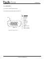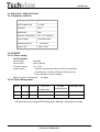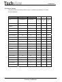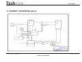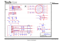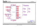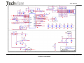
1
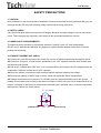
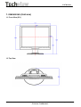
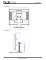
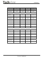
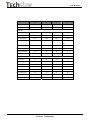
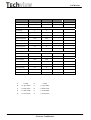
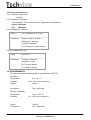
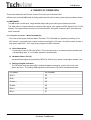
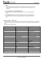
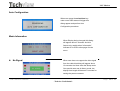
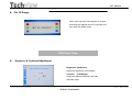
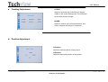
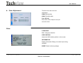
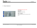
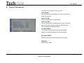
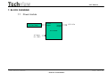
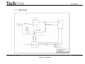
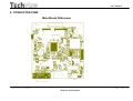
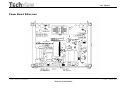
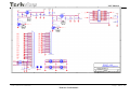
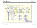
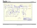
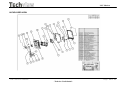
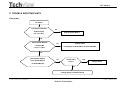
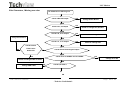
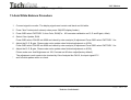
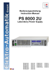
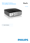
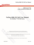
L9CMonitor
Service Manual for the Envision EN9410
Feb, 18th, 2005 Revision: 1A
Issued By:
Checked By:
_____________________________________________________________________________
____
The release of this document is under control by the company. Any extra
copy of this document must be written permission by the product manager.
L9C service manual
Page1 of 48
- Techview Confidential -
L9CMonitor
_____________________________________________________________________________
____
- Quanta Confidential –
History Page
Reversion
1A
Date
2/18/2005
ST
1
Remark
Released.
L9C service manual
Page2 of 48
- Techview Confidential -
L9CMonitor
Content
Chapter
A. WARNING
B. SAFETY PRECAUTIONS
1. DIMENSIONS
2. GENERAL INFORMATION
3. SPECIFICATIONS
4. THEORY OF OPERATION
5. CONTROL LOCATION
6. NECESSARY EQUIPMENT LIST
7. BLOCK DIAGRAM
8. CONDUCTOR VIEW
9. SCHEMATIC DIAGRAM
10. EXPLODED VIEW
11. TROUBLE SHOOTING HINTS
12. REPLACEMENT PARTS LIST
13. AUTO BALANCE
L9C service manual
Page
4
5
6
8
9
20
23
32
33
35
38
45
46
48
48
Page3 of 48
- Techview Confidential -
L9CMonitor
WARNING
This service information is designed for experienced repair technicians only and is
not designed for use by the general public
It does not contain warnings or cautions to advise non-technical individuals of
potential dangers in attempting to service a product.
Products powered by electricity should be serviced or repaired only by
experienced professional technicians.
Any attempt to service or repair the product or products dealt within this service
information by anyone else could result in serious injury or death.
L9C service manual
Page4 of 48
- Techview Confidential -
L9CMonitor
SAFETY PRECAUTIONS
1. CAUTION:
No modification of any circuit should be attempted. Service work should only be performed after you are
thorough familiar with all of the following safety checks and servicing guide lines.
2. SAFETY CHECK
Care should be taken while servicing this LCD display. Because the high voltage is used in the inverter
circuit. These voltages are exposed in such areas as the associated transformer circuits.
3. POWER SUPPLY REQUIREMENTS
The external power converter for this display utilizes AC and DC cords. AC cord is detachable,
But DC cord is permanently attached. Any attempt to replace another adapter could result in serious
problem on the display.
4. LEAKAGE CURRENT HOT CHECK
4-1 Plug the AC cord directly into the AC outlet. Do not use an isolation transformer during this check.
4-2 Connect a 1500 ohm, 10 watt resistor, paralleled by a 0.15uF capacitor between each metallic part
and a good earth ground.
4-3 Use an AC voltmeter with 1000 ohm / volt or more sensitivity and measure the AC voltage across the
combination 1500 ohm resistor and 0.15uF capacitor.
4-4 Move the resistor connection to each exposed metallic part and measure the voltage.
4-5 Reverse the polarity of the AC plug in the AC outlet and repeat the above measurement.
4-6 Voltage measured must not exceed 1.5 volt RMS, from any exposed metallic part to the ground.
A
leakage current tester may be used in the above hot check, in which case any circuit measured must not
exceed 1 milliamp. In the case of a measurement exceeding the 1 milliamp value, a rework is required to
eliminate the chance of a shock hazard.
AC VOLTMETER
V
0.15u
.
To Metal Parts
1500
10W
Earth Ground
L9C service manual
Page5 of 48
- Techview Confidential -
L9CMonitor
1. DIMENSIONS (Unit:mm)
1.1 Front View (ID1)
1.2 Top View
L9C service manual
Page6 of 48
- Techview Confidential -
L9CMonitor
1.3 Rear View
1.4 Side View
L9C service manual
Page7 of 48
- Techview Confidential -
L9CMonitor
2. GENERAL INFORMATION
2.1. OUTLINE
This monitor is 19" multi-scan color LCD display with the following features OSD (on screen display)
control allows easy user adjustment . Power saving function, which helps saving energy, is also one of
the highlights of this model.
2.2. FEATURES
2.2.1 Power Saving
Built in Power Saving function based on VESA-DMPS standard. Power energy shall be saved
by controlling the circuit in accordance with power save signal from computer.
2.2.2 OSD (on screen display) function
OSD ( 3 Languages ) function is excellent and new man-machine interface.
Anyone is able to set up the picture as the like through OSD menu.
2.2.3 Self Test function
Self Testing picture comes out by pushing any key in the case of no-connection with computer
or power saving operation. This function shows if monitor is alive or not and can be used for self
aging test.
2.2.4 Ergonomic design
Low emission design to meet MPR II and TCO
2.2.5 Multi scan with digital technology
8 bit micro controller controls the circuit operation to meet with wide range signal of
Fh=31~83 kHz and Fv= 56~75 Hz. So VGA720x400, VGA640x480, SVGA800x600,XGA 1024x768,
SXGA 1280x1024 .
2.2.6 Factory preset
The product has 32 memory mode in total ,15 modes are preset and 17 modes are user
definable.
2.2.7 Fine dot pitch
LCD panel with a fine dot pitch (Horizontal: 0.294 mm / Vertical: 0.294mm)
2.2.8 Superior display performance
High contrast: 500: 1(Typical)
High brightness: 250 cd / m2 (Typical)
Wide view angle: 140/ 130degrees (H/V)
2.2.9 Special function
VESA DDC2B (Display Data Channel) Compatible
L9C service manual
Page8 of 48
- Techview Confidential -
L9CMonitor
3. SPECIFICATION
3.1. Outline
3.1.1 Front Indication: POWER SW, LED (Green/Amber), UP, Down, LEFT, RIGHT, Set/Auto and
MENU key are located on the front panel.
3.1.2 Video signal cable connector, and DC inlet are located on the backside cabinet.
3.1.3 OSD menu includes the following function. CONTRAST, BRIGHTNESS, H.POSITION,
V.POSITION
COLOR-TEMPERATURE, CLOCK, PHASE, LANGUAGE, VOLUME, POWER-ON-RECALL
3.1.4 CONTRAST and BRIGHTNESS can be directly controlled with UP / Down key.
3.1.5 VOLUME can be controlled with LEFT / RIGHT key.
3.2. MECHANICAL SPECIFICATIONS
3.2.1 Dimension
Height: 437mm
Width: 426mm
Depth: 198mm
3.2.2 Net Weight:
5.0 kg
3.2.3 Maximum Viewable Area: Diagonal 482.6mm(19")
3.3. PANEL SPECIFICATIONS
Part No.
CLAA190EA03
Driver bit of panel
8bit + dithering
Contrast ratio
500:1
Brightness
250 cd/ m2
Pixel pitch
0.294 mm
Response time
Typical 16 ms
View angle
70/70/70/60degree
Color coordinate
x=0.313,y=0.329
L9C service manual
Page9 of 48
- Techview Confidential -
L9CMonitor
3.4. CONNECTORS
3.4.1 AC inlet : CEE22 typed connector
3.4.2 Attached video signal cable connector x 1
Shell
1
2
3
4
5
10
6
11 12 13
14 15
Figure 3.4
Pin
Signal Name
1
2
3
4
5
6
7
8
9
10
11
12
13
14
15
Red video
Green video
Blue video
Ground
Ground
Red ground
Green return
Blue return
N/C
Ground
Ground
SDA (serial data)
Hsync
Vsync (VCLK)
SCL (serial clock)
Signal cable input connector.
L9C service manual
Page10 of 48
- Techview Confidential -
L9CMonitor
3.5. ELECTRICAL SPECIFICATIONS
3.5.1 Standard conditions
Display area (HxV)
378.3*303mm
Video signal level
0.7 Vpp
Contrast
Max.
Brightness
Max.
Ambient Temperature
25 +/- 5 C degrees
Input voltage
Universal power
Warming up time
At least 30
1280 x 1024
Display mode
3.5.2 POWER
3.5.2.1 Power supply
AC-DC adapter
Input voltage
Input current
Frequency range
100-240V
Max. 0.8Arms
47 - 63 Hz
Inrush current
Shall be less than the ratings of critical components
(Including fuse, rectifiers and surge limiting device)
for all conditions of line in voltage.
Maximum power consumption:
50 Watts
3.5.2.2 Power Management
MODE
H-SYNC
V-SYNC
COLOR OF
POWER LED
POWER
RECOVERY TIME
CONSUMPTION
On
Active
Active
Green
< 50 Watts
-
Off
Inactive
Inactive
Amber
< 1 Watts
< 5 seconds
At first power on w/o signal LED will be green blinking + message on screen.
L9C service manual
Page11 of 48
- Techview Confidential -
L9CMonitor
3.5.3 Signal level and input impedance
3.5.3.1 Video Signal level
This LCD display is adjusted at the factory using 0,7 Vp-p Video signal.
3.5.3.2 Sync Signal level
H/V Separate: TTL level
3.5.3.3 Input impedance
Video input: 75 ohms +/- 1%
Sync input: > 1 k ohms
3.5.4 Display Area
Display area: 378.3*303mm
L9C service manual
Page12 of 48
- Techview Confidential -
L9CMonitor
3.5.5 Preset Timings
The product has 32 memory modes in total. 15 modes are preset and 17 modes
are user definable.
Format
Pixel Clock(MHz)
1
2
640x350@70Hz
720x400@70Hz
3
4
5
640X480@6 640x480@7 640x480@7
0Hz
2Hz
5Hz
25.176
28.320
25.175
31.500
31.500
P
N
N
N
N
Frequency(KHz)
31.470
31.467
31.469
37.861
37.500
Total Time(pixels)
800
900
800
832
840
Display Time(pixels)
640
720
640
640
640
Sync Width(pixels)
96
108
96
40
64
Back Porch(pixels)
48
54
40
120
120
Front Porch(pixels)
16
18
8
16
16
Blank time(pixels)
160
180
144
176
200
N
P
N
N
N
70.089
70.082
59.940
72.809
75.00
Total Time(lines)
449
449
525
520
500
Display Time(lines)
350
400
480
480
480
Sync Width(lines)
2
2
2
3
3
Back Porch(lines)
60
35
25
20
16
Front Porch(lines)
37
12
2
1
1
Blank time(lines)
99
49
29
24
20
Horizontal
Sync Polarity
Vertical
Sync Polarity
Frequency(Hz)
L9C service manual
Page13 of 48
- Techview Confidential -
L9CMonitor
6
7
8
9
800x600@56Hz
800x600@60Hz
800x600@72Hz
800x600@75Hz
36.000
40.000
50.000
49.500
P
P
P
P
Frequency(KHz)
35.156
37.879
48.077
46.875
Total Time(pixels)
1024
1056
1040
1056
Display Time(pixels)
800
800
800
800
72
128
120
80
Back Porch(pixels)
128
88
64
160
Front Porch(pixels)
24
40
56
16
Blank time(pixels)
224
256
240
256
P
P
P
P
56.250
60.317
72.188
75.000
Total Time(lines)
625
628
666
625
Display Time(lines)
600
600
600
600
Sync Width(lines)
2
4
6
3
Back Porch(lines)
22
23
23
21
Front Porch(lines)
1
1
37
1
Blank time(lines)
25
28
66
25
Format
Pixel Clock(MHz)
Horizontal
Sync Polarity
Vertical
Sync Polarity
Frequency(Hz)
L9C service manual
Page14 of 48
- Techview Confidential -
L9CMonitor
10
Format
Pixel Clock(MHz)
1024x768@60Hz
11
12
1024X768@70Hz 1024X768@72Hz
13
1024X768@75Hz
65.00
75.000
78.000
78.750
N
N
N
P
Frequency(KHz)
48.363
56.476
58.036
60.023
Total Time(pixels)
1344
1328
1344
1312
Display Time(pixels)
1024
1024
1024
Horizontal
Sync Polarity
1024
Sync Width(pixels)
136
136
132
96
Back Porch(pixels)
160
144
164
176
Front Porch(pixels)
24
24
24
16
Blank time(pixels)
320
304
320
288
N
N
N
P
60.004
70.069
71.916
75.029
Total Time(lines)
806
806
807
800
Display Time(lines)
768
768
768
768
Sync Width(lines)
6
6
6
3
Back Porch(lines)
29
29
30
28
Front Porch(lines)
3
3
3
1
Blank time(lines)
38
38
39
32
Vertical
Sync Polarity
Frequency(Hz)
L9C service manual
Page15 of 48
- Techview Confidential -
L9CMonitor
14
15
1280x1024@60Hz
1280x1024@75Hz
108.000
135.000
P
P
Frequency(KHz)
63.981
79.976
Total Time(pixels)
1688
1688
Display Time(pixels)
1280
1280
Sync Width(pixels)
112
144
Back Porch(pixels)
248
248
Front Porch(pixels)
48
16
Blank time(pixels)
408
408
P
P
60.020
75.025
Total Time(lines)
1066
1066
Display Time(lines)
1024
1024
Sync Width(lines)
3
3
Back Porch(lines)
38
38
Front Porch(lines)
1
1
Blank time(lines)
42
42
Format
Pixel Clock(MHz)
NA
NA
Horizontal
Sync Polarity
Vertical
Sync Polarity
Frequency(Hz)
A
: H-Total
O
: V-Total
B
: H- Sync width
P
: V- Sync width
C
: H- Back porch
Q
:.V- Back porch
D
: H- Video width
R
: V- Video width
E
: H- Front porch
S
:.V- Front porch
L9C service manual
Page16 of 48
- Techview Confidential -
L9CMonitor
3.5.6 General performance
3.5.6.1 Maximum pixel clock
135 MHz
3.5.6.2 Maximum luminance
Test conditions: 100% all white pattern, brightness set to Maximum
typical: 250 cd/m2
min :
200cd/m2
3.5.6.3 Brightness variation
Value
75 % Variation (C / A x 100)
Conditions
Display image: Full white
Brightness : Maximum
Contrast : Maximum
A: Luminance at center position
3.5.6.4 Contrast ratio (CR)
Value
CR= B / A
Conditions
Contrast : Maximum
Brightness : max
B: Full white pattern
A: Full black pattern
3.6. ENVIRONMENTS
The environmental conditions are in accordance to IEC 721
Operating:
Temperature:
Humidity:
0°C - +40° C
20% - 80% non–condensing
Height:
3658 m
Air pressure:
700 - 1060 mbar
Storage (unpacked)
Temperature:
Humidity:
-20°C - +60° C
8% - 95% non–condensing
Height:
12193 m
Air pressure:
700 - 1060 mbar
L9C service manual
Page17 of 48
- Techview Confidential -
L9CMonitor
Transport (packed)
Temperature:
Humidity:
Height:
-20°C - +60° C
8% - 95% non–condensing
12000 m
L9C service manual
Page18 of 48
- Techview Confidential -
L9CMonitor
3.7. REGULATORY STANDARDS
3.7.1 Safety standards
This monitor applies to various safety & EMI standards May refer to the logo label
3.7.2 EMC standards
FCC part 15,subpart B , class-B (EMV) CE marking
3.8. OTHERS
UL, cUL,
3.9. P0WER CORD
Northern Hemisphere Version: UL / CSA
approved power cord.
European: VDE approved power cord.
3.10. SIGNAL CABLE
Signal cable with Mini D-Sub 15P connectors. Length: 1.8 meter.
3.11. RELIABILITY
> 30000hrs (demonstrated MTBF)
L9C service manual
Page19 of 48
- Techview Confidential -
L9CMonitor
4. THEORY OF OPERATION
This section describes the function of the LCD monitor per functional block.
L9EA monitor includes MB Board (including audio board function inside), power board and button board.
4.1 MB BOARD
The MB board is a two-layer, single-landed design with ground and ground planes provided.
The VGA cable is a signal cable that contains video signal, sync signal and DDC signal from PC VGA
adapter This system board consists of 3 functional areas : flat panel controller, Micro controller and
audio controller.
4.1.1 Flat panel controller… Mstar TSU16AK (U3)
The heart of the system board is Mstar TSU16AK. The TSU16AK is a graphics processing IC for
LCD monitor. It provides some control functions required for LCD panel. On-chip functions include a
high-speed triple-ADC , PLL, high sacling engine and OSD controller.
a) Clock Generation :
Crystal Input Clock (XTALI and XTAL). This is the input pair to an internal crystal oscillator and
corresponding logic. A 14.318 MHz crystal is recommended.
b) Hardware Reset ( Pin 32 )
Hardware Reset signal is generated by MTV312 (U5/Pin 26).It assert a reset signal at least 1 ms.
c) Analog to Digital Converter
The TSU16AK chip has three ADC's (analog-to-digital converters), one for each color (red,
green and blue) . The analog RGB signals are connected to TSU16AK as described below
Pin Name
Pin Number
Red +
63
Red -
62
Green +
60
Green -
59
Blue +
58
Blue -
57
L9C service manual
Page20 of 48
- Techview Confidential -
L9CMonitor
d) OSD :
The TSU16AK has a fully programmable, high-quality OSD controller. The on-chip
Static RAM (256 different fonts at size of 12X18) stores the cell map and the cell
definitions.
e) Inverter Brightness control (PWM0) (Pin 73)
The TSU16AK has one PWM output PWM0(Pin73) to control Inverter Brightness
Range.
f) Panel LVDS interface (Pin 102~103, Pin106~113, Pin118~125, Pin128, Pin1)
The TSU16AK driver interface is highly programmable. It supports LVDS port for
panel.
4.1.2 Micro controller……MTV312 (U5)
The MYSON MTV312 microcontroller serves as the system microcontroller.That is , it programs the
TSU16AK and manages other devices in the system such as the keypad, the backlight, LED and
audio
general purpose input/output pins.
Pin number
23
22
16
21
41
9
25
24
29
28
19
18
20
26
42
37
40
36
3
Pin name
P1.5
P1.4
P6.2
P1.3
P5.4
P6.3
P1.7
P1.6
P3.0/RXD/HSCL
P3.1/TXD/HSDA
P3.2/INT0
P1.1
P1.2
P6.1/AD1
P5.3
P4.1
P5.5
P4.0
P5.0
L9C service manual
Pin function
Key-Sel/Auto
Key-Menu
Key-Left
Key-Power on/off
LED-Green
Key-Right
Key-Down
Key-Up
SCL-VGA/RxD(Debug)
SDA-VGA/Txd(Debug)
INT
SDA(Debug)
SCL(Debug)
RESET
LED-Orange
Audio-Mute
Audio-Stby-Power
Inverter On/Off
Panel power On/Off
Page21 of 48
- Techview Confidential -
L9CMonitor
4.2
Power Module
The power module includes an Inverter and Power regulator. The electrical specification
described as following:
4.2.1 Power Characteristics.
Input
Rated Input Voltage
90~240 Vac,50/60Hz
Operation Input Voltage Range
90~264 Vac,47~63Hz
Max Input AC Current
< 1.2A
Efficiency
12Vdc load 3.5A
Brightness Voltage from 0.3~3Vdc
ON/OFF Voltage : High(3.3Vdc)/Low(0Vdc)
Output
Brightness Voltage(Vadj)
0.3Vdc(Max) ~ 3Vdc(Min)
On/Off Voltage
High(3.3Vdc)/Low(0Vdc)
Static Output Characteristics
12V/3.5A Output : 11.4Vdc ~ 12.6Vdc
4.2.2 Inverter output characteristics.
Rated Output Kick-off Voltage
1500 ~ 2000 Vrms
Rated output Voltage
720Vrms
Rated Output Frequency
40 ~ 60 Khz
Rated Output Current per tube
7mArms
4.2.4 Power module of connector definition ;
CN110 ;
Pin 1 & 2 ----> Vdc Output ( 12V +/- 5%)
Pin 3 & 4 ---------> GND
Pin 5 ---------> Brightness Control Voltage
Pin 6 ---------> On /Off ( "High" set Lamp on )
CN1 ~ CN4 ;
Pin 1 ---------> HV ( High Voltage for CCFL )
Pin 2 ---------> Return ( Low Voltage for CCFL )
L9C service manual
Page22 of 48
- Techview Confidential -
L9C Monitor
5 CONTROL LOCATION
Button Define
1
OSD Menu
Trigger OSD Main Menu / Clear OSD
2
UP
1. Select OSD Main Menu Item
2. Trigger Brightness/Contrast Menu.
3
DOWN
1. Select OSD Main Menu Item
2. Trigger Brightness/Contrast Menu.
4
POWER
5
LEFT
1. Decrease Menu Item value
2. Trigger Volume Menu.
6
RIGHT
1. Increase Menu Item value
2. Trigger Volume Menu.
7
SELECT/ AUTO
Switch Power ON/OFF
1. Switch OSD Main Menu focus status.
2. Perform Auto configuration.
L9C service manual
Page
-Techview Confidential -
23of 48
L9C Monitor
LED Status
Color
Green
Status Description
Normal status
Enter Sleep Mode status or use “Power + Auto” key
Amber
enter factory mode
L9C service manual
Page
-Techview Confidential -
24of 48
L9C Monitor
Dialog Overview
OSD Main Menu
When user press the Menu key under none
OSD status will trigger this menu appear for
detail parameters adjust. This menu will
display about 20 seconds if no one press
other key, otherwise will refresh display
time length.
Brightness/Contrast Menu
When user press the Up or Down keys
under none OSD status will trigger this
menu appear for Brightness and
Contrast adjust. This menu will display
about 20 seconds.
L9C service manual
Page
-Techview Confidential -
25of 48
L9C Monitor
Auto Configuration
When user press the select/Auto key
under none OSD status will trigger this
dialog appear and perform Auto
Configuration procedure.
Mode Information
When Display timing changed this dialog
will appear about 3 seconds. And this
feature only enable when “Information”
indicate On in OSD’s other page of main
menu.
No Signal
When user does not support the video signal
from the cable this dialog will appear about
10 seconds. And then enter the Sleep mode.
One special case was in factory mode, the
display time length will become 5 seconds for
testing the power consumer.
L9C service manual
Page
-Techview Confidential -
26of 48
L9C Monitor
Out Of Range
When user input the video signal out of spec
this dialog will appear about 10 seconds. And
then enter the Sleep mode.
OSD Main Menu
Brightness & Contrast Adjustment
Brightness (Up&Down):
Adjust the brightness of the display.
Contrast
(Left&Right):
Adjust the difference between the light
and dark areas.
L9C service manual
Page
-Techview Confidential -
27of 48
L9C Monitor
Tracking Adjustment
CLOCK:
Adjust to minimize any vertical bars or stripes
visible on the screen background. The horizontal
screen size will also change.
PHASE:
Adjust to remove any horizontal distortion, and
clear or sharpen the image of characters.
Position Adjustment
V-Position:
Adjust the vertical position of the picture.
H-Position:
Adjust the horizontal position of the picture.
L9C service manual
Page
-Techview Confidential -
28of 48
L9C Monitor
Color Adjustment
There are four items for color
adjustment:
9300K: Bluish white
6500K: Reddish white
User defined:
Red, Green, Blue. Adjust to set your
own color level.
Other
LANGUAGE:
Multi- Language selection
OSD POSITION:
Adjust the OSD window position on the screen.
INFORMATION:
Display Information Dialog or not when input timing
changed.
RESET: Recall to factory settings.
L9C service manual
Page
-Techview Confidential -
29of 48
L9C Monitor
Factory1 Adjustment
This page only visible in factory mode
R,G,B OFFSET :
Adjust current RGB cut off level
R,G,B GAIN :
Adjust current RGB Driver value.
SSPLL and SSMOD :
Adjust chip set internal frequency spread effect for EMI
testing.
L9C service manual
Page
-Techview Confidential -
30of 48
L9C Monitor
Factory2 Adjustment
This page only visible in factory mode
AUTO BURN :
Use the chip set internal pattern for hot running monitor
panel and inverter.
AUTO COLOR :
Perform Auto Balance measurement .
AUTO COLOR 1 :
Perform Auto Balance measurement by chip set internal
signal. And reference these values to initial all other
color temperature detail parameters.
COLOR UPDATE :
Force presently R,G,B offset and gain parameters
update to currently temperature memory address.
FACTORY RESET :
Recall to factory setting and power off immediately.
VERSION :
Display F/W version.
L9C service manual
Page
-Techview Confidential -
31of 48
L9C Monitor
6. NECESSARY EQUIPMENT LIST
1
2
3
4
5
6
Item
Personal Computer with Windows 98/95
Luminance Meter Minolta CA 110
Video Generator : Chroma 2000,2135,2250 or equivalent
Color Analyzer : Minolta CA110 , Chroma or equivalent
Watt / Power Meter
10 Times Magnifier
7 Ruler /Template
8 Thickness gauge
L9C service manual
Page
-Techview Confidential -
32of 48
L9C Monitor
7. BLOCK DIAGRAM
7.1 Power module
To Panel lamp
Inverter
Output
Voltage
Output
12V/3.25A
Power Module
AC Input
90 ~ 264V
L9C service manual
Page
-Techview Confidential -
33of 48
L9C Monitor
7.2 Main Board
L9C service manual
Page
-Techview Confidential -
34of 48
L9C Monitor
8. CONDUCTOR VIEW
Main Board Silkscreen
L9C service manual
Page
-Techview Confidential -
35of 48
L9C Monitor
Power Board Silkscreen
L9C service manual
Page
-Techview Confidential -
36of 48
L9C Monitor
Button Board Silkscreen
L9C service manual
Page
-Techview Confidential -
37of 48
L9C Monitor
9. SCHEMATIC DIAGRAM Main Board
L9C service manual
Page
-Techview Confidential -
38of 48
L9C Monitor
L9C service manual
Page
-Techview Confidential -
39of 48
L9C Monitor
L9C service manual
Page
-Techview Confidential -
40of 48
L9C Monitor
L9C service manual
Page
-Techview Confidential -
41of 48
L9C Monitor
L9C service manual
Page
-Techview Confidential -
42of 48
L9C Monitor
Power Board Circuit
L9C service manual
Page
-Techview Confidential -
43of 48
L9C Monitor
L9C service manual
Page
-Techview Confidential -
44of 48
L9C Monitor
10.EXPLODED VIEW
L9C service manual
Page
-Techview Confidential -
45of 48
L9C Monitor
11 TROUBLE SHOOTING HINTS
1.No power
No Power
Check Power Module
NO
Output CN110
Change Power Board
Pin 1,2 = 12V?
OK
Check Scalar Module
Change Cable
NO
Output CN6
From(Power module)CN110 to (Scalar/B)CN6
Pin 1,2 = 12V?
OK
Check Power Button
From Scalar/B(CN4)
to Button/B(CN1)
NO
Check Cable
YES
Open?
Change Cable
NO
Change Switch or Button Board
L9C service manual
Page
-Techview Confidential -
46of 48
L9C Monitor
2.No Characters , Missing one color
No Characters or Missing one
Check CN6 12V Output
NO
Change Power Board
OK
Check L33 , 5V Output
NO
Check or Change U21,Q13,Q17
OK
Check L34 , 2.5V output
NO
Check or Change U22
Change Power Board
OK
Check L31 , 3.3V output
Check Inverter
NO
NO
Check or Change U23
OK
From Power
Check CN9 to Panel Signal Output
board OK?
OK
NO
Check X’Tal 11.059Mhz and 14.318Mhz
Check or Change Cable or Panel
NO
Change X1 or X2
OK
Change VGA Cable
NO
Check H,V SYNC?
OK
L9C service manual
Page
-Techview Confidential -
47of 48
L9C Monitor
12. REPLACEMENT PARTS LIST( See appendix)
13.Auto White Balance Procedure
1
Connect signal to monitor. The display signal need contain real black and full white.
2
Press "Auto" button(don't release) when power ON(LED display Amber).
3
Press OSD select FACTORY 2, Auto Color, RUN(For AD converter calibration on R, G and B gain, offset).
4
5
Select Color Update, RUN.
Press OSD select COLOR into 6500 and check by color analysis (If adjustment Press OSD select FACTORY 1 for
Adjust the R, G, B gain. Please make color update when finished adjustment on 6500)
6
Press OSD select COLOR into 9300 and check by color analysis (If adjustment Press OSD select FACTORY 1 for
Adjust the R, G, B gain. Please make color update when finished adjustment on 9300)
Please make sure that Brightness set 100, Contrast set 80 when adjust(factory default).
The adjustment result needs to be checked by Color Analysis like CA110, the input signal 0.7V
*
and full white pattern while on check.
L9C service manual
Page
-Techview Confidential -
48of 48