1
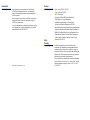
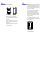
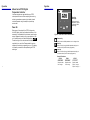
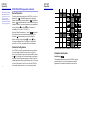
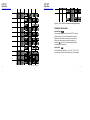
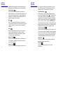
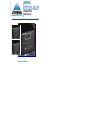
SERIES
OTC25-N/L/P
TEMPERATURE
CONTROLLER
Instruction Manual
Introduction
Features
Congratulations on your purchase of an Athena Series
OTC25 Digital Temperature Controller. It is designed for
ease of use and reliability wherever accurate temperature
control is required.
• Type J Input (OTC25 N, OTC25 L)
• Type J or K Input (OTC25 P)
• ±0.3% FS Accuracy
• Large, Easy-to-Read LED Display, Selectable for
Either Setpoint or Process Temperature
After following the instructions for installation, simply step
through and set each of the unit’s parameters using the
OTC25’s easy menu system.
• Adjustable Output Hysteresis to Prevent Rapid
Cycling Around Setpoint Temperature (OTC25 N)
If you still have questions or require any assistance in setting
up or operating your controller, please contact your Athena
representative or call 1-800-782-6776.
• Adjustable Deviation Alarm Flashes Display When Measured
Temperature Exceeds or Falls Below Setpoint Temperature
• NEMA 4X Front Bezel, Splash-Proof and Resistant to Dust
• Discrete Status Indicators Illuminate When Temperature
Display, Setpoint Display or Heat/Cool Output is Active
Safety
Warning
• Approvals: UR, cUR, CE
In addition to presenting a potential fire hazard, high
voltage and high temperature can damage equipment and
cause severe injury or death. When installing or using this
instrument, follow all instructions carefully and use approved
safety controls. Electrical connections and wiring should be
performed only by suitably trained personnel.
© Copyright 1996, Athena Controls, Inc.
i
Do not locate this instrument where it is subject to excessive
shock, vibration, dirt, moisture, oil, or other liquids. The safe
operating temperature range for this unit is 32° F to 140° F
(0° C to 60° C).
ii
Table of
Contents
Installation
Installation
Mounting
Wiring
Operation
1
2
3
OTC25 N On/Off Controller
OTC25 L Limit Controller
OTC25 P PID Controller
4
6
10
13
Calibration
Error Codes
IEC Requirements
Warranty/Repair Information
Technical Specifications
18
20
21
22
25
Pre-Installation Instructions
1. Inspect shipping carton for obvious signs of mishandling.
2. After removing the controller from the shipping carton,
inspect it carefully for damage. Never attempt to install
and use a damaged unit.
3. Verify that the ordering code number indicated on the side
of the controller matches what was ordered.
Figure 1. Case Dimensions
Prior to mounting the OTC25 in your panel, make sure
that the cutout opening is of the right size, 3.622" x 3.622"
(92 mm x 92 mm), and deburred to enable a smooth fit.
A minimum of 5.0" (127.0 mm) of depth behind the panel
is required.
iii
1
Mounting
Wiring
Figure 2. Mounting Diagram
IMPORTANT: All electrical wiring connections should be made
only by trained personnel using Class 1 wiring, and in strict
accordance with the National Electrical Code and local regulations. Both of the incoming power lines should be fused with
2AG, 0.5 A maximum rated fuses.
The OTC25 controller has built-in circuitry to reduce the
effects of electrical noise (RFI) from various sources;
however, power and signal wires should always be kept
separate. We recommend separating wires into one bundle
for power (from line power and output) and one bundle for
signal (from thermocouple).
Before installing OTC25, ensure gasket seats evenly
around edges of unit and that there are no breaks or tears
in the gasket.
The OTC25 power supply accepts 100 through 250 Vac and
120 through 250 Vdc line power without any switch settings
or polarity considerations.
Insert the OTC25 through the front panel cutout, slide
mounting “U” bracket around unit and secure it with the
screws provided.
Gasket should be evenly compressed around all sides to
provide liquid-tight mounting.
Figure 3. Wiring Connections
2
3
Operation
Operation
Athena Series OTC25 Digital
Temperature Controller
Just a few easy steps are required before your OTC25
can be placed into service. After completing the mounting
and wiring procedures as previously instructed, set each
controller parameter using the simple front-panel keys
as instructed.
Three-Digit
LED Display
Displays measured
temperature, setpoint,
or parameter labels
and settings.
Power On
When power is first applied to the OTC25, all segments
of the LED display, as well as the discrete indicators, will be
momentarily illuminated while the instrument goes through a
series of diagnostic checks to verify proper operation of the
unit. A software version will then be displayed, e.g.,
.
The last two digits of this code indicate the software revision
supplied with your controller. Please provide this revision
number when contacting us regarding your unit. This display
is followed by a mnemonic code representing the OTC25
model type.
Figure 4. Front Panel Controls and Indicators
Parameter Key
Used to access available parameters to set or change values.
Raise Key
Used to scroll up through available parameter settings or to
increase values. (Hold for fast-step progression)
Lower Key
Used to scroll down through available parameter settings or
to decrease values. (Hold for fast-step progression)
Discrete LED Indicators
OTC25 N
OTC25 L
Actual: amber
Actual: amber
Setpoint: amber
Setpoint: amber
Heat: orange
Limit: orange
4
OTC25 P
Actual: amber
Setpoint: amber
Output 1: orange
Output 2: orange
5
OTC25 N
Operation
OTC25 N
Operation
OTC25 N On/Off Temperature Controller
The Calibration High
and Calibration Low
selections are accessible only when the
calibration jumper is
installed as instructed
on page 18 (Figure 6).
Normal Operation
The factory default display setting of the OTC25 N is for Actual
Temperature
. The default display may be changed to
setpoint temperature by selecting Setpoint
at the Default
Display
parameter selection. When the Default Display is
changed to Setpoint, the setpoint temperature may be adjusted
by using the Raise
or Lower
keys. The setpoint is
adjustable from 32 to 905° F (0 to 485° C).
When the Default Display setting is “Actual”
, adjustment
of the Setpoint may only be accomplished by pressing the
Parameter
Key momentarily to switch the display to
Setpoint, and then using the Raise
or Lower
Keys
to change the Setpoint Value. The display will automatically
revert back to “Actual” five seconds after the last keypress.
Parameter Configuration
Your OTC25 N controller’s parameter selections are explained
on the next page, with default settings shown in Figure 5a.
To enter the configuration menu, press and hold the Parameter
key
for 10 seconds until the display changes to the parameter mode. Press the Parameter key again to index through the
available parameters. Pressing the Parameter Key for 3 seconds
or allowing 60 seconds of inactivity will cause the OTC25 N to
exit the menu system and return to normal operating mode.
6
Figure 5a. Series OTC25 N Parameters and Default Settings
Parameter Descriptions
Default Display
This parameter determines whether the OTC25 N’s display
shows the Setpoint or the actual temperature by default.
Regardless of the selection made here, the operator can
7
OTC25 N
Operation
OTC25 N
Operation
observe the other value by momentarily pressing the
Parameter
Key. This will cause the alternate value to be
displayed for five seconds.
Control Hysteresis is adjustable between 2 and 252° F (1 to
140° C ). This parameter is used by the control algorithm to
prevent rapid cycling of the output around Setpoint. The
default value is 4° F (2° C). This means the heat will turn OFF
when the Actual Temperature exceeds the Setpoint by 2° F
(1° C). Conversely, the heater will not turn ON until the Actual
Temperature drops 2° F (1° C) below the Setpoint.
A Deviation Band is a pre-set number of degrees, plus and
minus, around the Setpoint Value, ex. +10° F. A Deviation
Band Alarm provides an indication to the operator that the
Actual Temperature has either exceeded or dropped below
the chosen deviation. This parameter can be turned off
or adjusted from 1 to 252° F (1 to 140° C). When the process
variable is outside the deviation band, the alarm is indicated
by flashing the display (regardless of whether setpoint or
actual temperature is displayed) and the optional alarm
output is activated.
Display Offset
Display Units
Display Offset is adjustable from -126 to 126° F (-70 to 70° C).
It can be used to provide limited adjustment of the displayed
temperature as a compensation for offsets between the true
temperature and the temperature seen by the thermocouple.
This allows the operator to have the display indicate either
degrees Fahrenheit or degrees Celsius.
Control Hysteresis
8
Deviation Band Alarm
9
OTC25 L
Operation
OTC25 L
Operation
OTC25 L Limit Controller
Normal Operation
The factory default display setting of the OTC25 L is for Actual
Temperature
. The default display may be changed to
setpoint temperature by selecting Limit Setpoint
at the
Default Display
parameter selection. When the Default
Display is changed to Limit Setpoint, the limit setpoint temperature may be adjusted by using the Raise
or Lower
keys.
The limit setpoint is adjustable from 32 to 905° F (0 to 485° C).
When the Default Display setting is “Actual”
, adjustment
of the Limit Setpoint may only be accomplished by pressing the
Parameter
Key momentarily to switch the display to Limit
Setpoint, and then using the Raise
or Lower
Keys to
change the Limit Setpoint Value. The display will automatically
revert back to “Actual” five seconds after the last keypress.
Parameter Configuration
Your OTC25 L controller’s parameter selections are explained
on the next page, with default settings shown in Figure 5b.
To enter the configuration menu, press and hold the Parameter
key
for 10 seconds until the display changes to the parameter mode. Press the Parameter key again to index through the
available parameters. Pressing the Parameter Key for 3 seconds
or allowing 60 seconds of inactivity will cause the OTC25 L to
exit the menu system and return to normal operating mode.
10
Figure 5b. Series OTC25 L Parameters and Default Settings
Parameter Descriptions
Default Display
This parameter determines whether the OTC25 L’s display
shows the Limit Setpoint or the actual temperature by
default. Regardless of the selection made here, the operator
can observe the other value by momentarily pressing the
Parameter
Key. This will cause the alternate value to
be displayed for five seconds.
11
OTC25 L
Operation
OTC25 P
Operation
Limit Setpoint
The Limit Setpoint determines the temperature at which
the limit output will become inactive, interrupting power to
the process. It is operator-selectable from 32° to 905° F
(0° to 485° C).
Automatic Startup Reset
The automatic startup reset feature allows the limit output to be
automatically reset at startup or to be latched at startup. In the
latter condition, the limit output will have to be manually reset
before the limit output will be activated (relay closed allowing
power to flow to process heaters or coolers).
Display Units
This allows the operator to have the display indicate either
degrees Fahrenheit or degrees Celsius.
OTC25 P PID Temperature Controller
Normal Operation
The factory default display setting of the OTC25 P is for Actual
Temperature
. The default display may be changed to
setpoint temperature by selecting Setpoint
at the Default
Display
parameter selection. When the Default Display is
changed to Setpoint, the setpoint temperature may be adjusted
by using the Raise
or Lower
keys. The setpoint is
adjustable from 0 to 999° F (-17 to 537° C).
When the Default Display setting is “Actual”
, adjustment
of the Setpoint may only be accomplished by pressing the
Parameter
Key momentarily to switch the display to
Setpoint, and then using the Raise
or Lower
Keys
to change the Setpoint Value. The display will automatically
revert back to “Actual” five seconds after the last keypress.
Parameter Configuration
Your OTC25 P controller’s parameter selections are explained
on the next page, with default settings shown in Figure 5c.
To enter the configuration menu, press and hold the Parameter
key
for 10 seconds until the display changes to the parameter mode. Press the Parameter key again to index through the
available parameters. Pressing the Parameter Key for 3 seconds
or allowing 60 seconds of inactivity will cause the OTC25 P to
exit the menu system and return to normal operating mode.
12
13
OTC25 P
Operation
OTC25 P
Operation
Figure 5c. Series OTC25 P Parameters and Default Settings
Parameter Descriptions
Default Display
This parameter determines whether the OTC25 P’s display
shows the Setpoint or the actual temperature by default.
Regardless of the selection made here, the operator can
observe the other value by momentarily pressing the
Parameter
Key. This will cause the alternate value to
be displayed for five seconds.
Display Offset
Display Offset is adjustable from -126 to 126° F (-70 to 70° C).
It can be used to provide limited adjustment of the displayed
chart continued on next page
14
15
OTC25 P
Operation
OTC25 P
Operation
temperature as a compensation for offsets between the true
temperature and the temperature seen by the thermocouple.
Proportional Band
Proportional Band is a PID parameter that represents the
amount of deviation of the controlled variable required to move
through the full range, expressed in % of span or degrees of
temperature. This parameter can also be expressed as “Gain”
(the wider the band, the lower the gain).
Rate
Rate is a PID parameter (Derivative Action) that produces a
corrective signal proportional to the rate at which the controlled
variable is changing. It is used to correct for overshoot and
undershoot.
Reset
Reset is a PID parameter (Integral Action) that produces a
corrective signal proportional to the length of time and
magnitude that the controlled variable has been off setpoint.
It is used to accommodate load changes.
Heat Cycle Time
Heat Cycle Time is displayed in seconds, and can be set from
0 to 120 seconds. A setting of zero represents a heat cycle
time of 300 milliseconds.
Cool Cycle Time
Cool Cycle Time is displayed in seconds, and can be set from
16
0 to 120 seconds. A setting of zero represents a cool cycle
time of 300 milliseconds. This menu parameter will only be
displayed if output 2 is configured to be a cool output.
Deviation Band Alarm
A Deviation Band is a pre-set number of degrees, plus and
minus, around the Setpoint Value, ex. +10° F. A Deviation Band
Alarm provides an indication to the operator that the actual
temperature has either exceeded or dropped below the chosen
deviation. This parameter can be turned off
or adjusted
from 1 to 252° F (1 to 140° C). When the process variable is
outside the deviation band, the alarm is indicated by flashing the
display (regardless of whether setpoint or actual temperature is
displayed and activating an output, if configured as such).
Output 2 Configuration
Output 2 may be configured as either a control output or as an
alarm output for the deviation band alarm. When configured for
control, output 2 acts as a cool PID output. When configured
for an alarm, output 2 is activated when the deviation alarm is
active and deactivated when the deviation alarm is inactive.
Display Units
This allows the operator to have the display indicate either
degrees Fahrenheit or degrees Celsius.
Input Type
Sensor input type may be either a Type J or Type K
thermocouple.
17
Calibration
Calibration
Calibration
The Calibration High
and Calibration Low
selections are accessible only when the
calibration jumper is
installed (Figure 6).
,
Calibration of the OTC25 controller requires the operator
to apply two separate fixed and specific signals (Calibration
Low and Calibration High) from a reference source
(thermocouple calibrator) to the controller. The Raise
Key “tells” the controller to read the applied signal and use
it as a reference point.
Calibration Procedure
1. Prior to applying power to the unit, install the calibration
jumper on the microprocessor board as shown in
Figure 6.
2. With the instrument still unpowered, connect a calibration
reference source to the thermocouple input terminals on
the OTC25.
3. Apply power. Allow at least 15 minutes for the controller to
warm up before continuing.
4. Using the Parameter
Key, index to the Calibration Low
parameter. The display will alternately flash this
mnemonic and the number “32” (“0” for Celsius units).
5. Adjust the reference source to output a voltage equivalent
to that generated by a “J” or “K” (OTC25 P) thermocouple
at 32° F (0° C). Allow reference to settle for 10 seconds
before proceeding.
Figure 6. Location of Calibration Jumper.
6. Press the Raise key
once to set this reference point.
The display will stop flashing momentarily while the
controller self-calibrates (approx. 3 seconds), and then
resume flashing.
7. Press the Parameter
Key, index to the Calibration High
parameter. The display will alternately flash this
mnemonic and the temperature value it expects to see.
18
19
IEC
Requirements
Calibration
8. Adjust the reference source to output a voltage equivalent
to that generated by a “J” or “K” (OTC25 P) thermocouple
at the temperature flashing on the display. (Allow reference
to settle for 10 seconds before proceeding.)
The maximum supply current is line voltage dependent:
9. Repeat Step 6 for this reference point.
60 mA for an 100-250 Vac input
10. Press the Parameter
Key for 10 seconds or allow
60 seconds of inactivity.
11. Adjust the reference source to output a voltage equivalent
to that generated by a “J” or “K” (OTC25 P) thermocouple
at 32° F (0° C). Verify that (after settling), the OTC25
indicates a measured temperature of 32° F (0° C).
12. Repeat Step 11 for the upper reference point.
Error Codes
fuse rating: 2AG, 0.5 A
Output Specifications
Output 1 Type
T (Triac)
B (Relay)
Max current
2A
5A
Voltage
400 Vpk
380 V
Leakage
1 mA
—
Output 2 Type
T (SSR)
B (Relay)
Max current
0.5 A
5A
Voltage
400 Vpk
380 V
Leakage
1 mA
—
CLEANING INSTRUCTIONS
Display
20
USE OF THIS EQUIPMENT IN A MANNER NOT SPECIFIED BY
THE MANUFACTURER MAY IMPAIR PROTECTION PROVIDED
BY THE EQUIPMENT!
Problem
Possible Solution
Broken thermocouple
lead wire or defective
sensor.
Verify wiring.
Replace sensor.
Input Signal is below
calibration of unit.
Verify Input Signal;
check calibration.
1. Remove power from the unit prior to any
cleaning operation.
2. Use a cotton cloth to gently and sparingly apply isopropyl
alcohol only. Do not use cleaners or other solvents as
they may damage the unit.
3. Allow the unit to dry completely prior to reapplying power.
21
Warranty/Repair
Information
Warranty/Repair
Information
Two-Year Limited Warranty
THIS EQUIPMENT IS WARRANTED TO BE FREE FROM
DEFECTS OF MATERIAL AND WORKMANSHIP. IT IS SOLD
SUBJECT TO OUR MUTUAL AGREEMENT THAT THE LIABILITY OF ATHENA CONTROLS, INCORPORATED IS TO REPLACE
OR REPAIR THIS EQUIPMENT AT ITS FACTORY, PROVIDED
THAT IT IS RETURNED WITH TRANSPORTATION PREPAID
WITHIN TWO (2) YEARS OF ITS PURCHASE.
THE PURCHASER AGREES THAT ATHENA CONTROLS,
INCORPORATED ASSUMES NO LIABILITY UNDER ANY CIRCUMSTANCES FOR CONSEQUENTIAL DAMAGES RESULTING
FROM ITS USE OR FROM IMPROPER HANDLING OR PACKAGING OF SHIPMENTS RETURNED TO THE FACTORY.
COMPONENTS WHICH WEAR OR WHICH ARE DAMAGED BY
MISUSE ARE NOT WARRANTED. THESE INCLUDE CONTACT
POINTS, FUSES, ELECTROMECHANICAL RELAYS, AND TRIACS. UNITS WHICH HAVE BEEN MODIFIED BY A CUSTOMER
IN ANY WAY ARE NOT WARRANTED.
IN NEGLIGENCE OR OTHERWISE SHALL NOT EXCEED THE
RETURN OF THE AMOUNT OF THE PURCHASE PRICE PAID
BY THE PURCHASER AND UNDER NO CIRCUMSTANCES
SHALL SELLER BE LIABLE FOR SPECIAL, INDIRECT, INCIDENTAL OR CONSEQUENTIAL DAMAGES. THE PRICE STATED FOR THE EQUIPMENT IS A CONSIDERATION IN LIMITING
SELLER’S LIABILITY. NO ACTION, REGARDLESS OF FORM,
ARISING OUT OF THE TRANSACTIONS OF THIS AGREEMENT
MAY BE BROUGHT BY PURCHASER MORE THAN ONE YEAR
AFTER THE CAUSE OF ACTION HAS ACCRUED.
SELLER’S MAXIMUM LIABILITY SHALL NOT EXCEED AND
BUYER’S REMEDY IS LIMITED TO EITHER (i) REPAIR OR
REPLACEMENT OF THE DEFECTIVE PART OR PRODUCT, OR
AT SELLER’S OPTION (ii) RETURN OF THE PRODUCT AND
REFUND OF THE PURCHASE PRICE, AND SUCH REMEDY
SHALL BE BUYER’S ENTIRE AND EXCLUSIVE REMEDY.
THE SPECIFICATIONS PUT FORTH IN THIS MANUAL ARE
SUBJECT TO CHANGE WITHOUT NOTICE.
Other than those expressly stated herein, THERE ARE NO
OTHER WARRANTIES OF ANY KIND, EXPRESS OR IMPLIED,
AND SPECIFICALLY EXCLUDED BUT NOT BY WAY OF LIMITATION, ARE THE IMPLIED WARRANTIES OF FITNESS FOR A
PARTICULAR PURPOSE AND MERCHANTABILITY.
IT IS UNDERSTOOD AND AGREED THE SELLER’S LIABILITY
WHETHER IN CONTRACT, IN TORT, UNDER ANY WARRANTY,
22
23
Warranty/Repair
Information
Technical
Specifications
Unit Repairs
It is recommended that units requiring service be returned to
an authorized service center. Before a controller is returned
for service, please consult the service center nearest you.
In many cases, the problem can be cleared up over the telephone. When the unit needs to be returned, the service center
will ask for a detailed explanation of problems encountered
and a Purchase Order to cover any charge. This information
should also be put in the box with the unit. This should expedite return of the unit to you.
This document is based on information available at the time
of its publication. While efforts have been made to render
accuracy to its content, the information contained herein does
not purport to cover all details or variations in hardware, nor
to provide for every possible contingency in connection with
the installation and maintenance. Features may be described
herein which are not present in all hardware. Athena Controls
assumes no obligation of notice to holders of this document
with respect to changes subsequently made.
Proprietary information of Athena Controls, Inc. is furnished
for customer use only. No other use is authorized without the
written permission of Athena Controls, Inc.
Operating Limits
Ambient Temperature
Relative Humidity
Tolerance
Power
Sensor Range
Type J Thermocouple
Type K Thermocouple
Performance
Accuracy
Setpoint Resolution
Repeatability
Temperature Stability
TC Cold-End Tracking
Noise Rejection
Temperature Sampling
Control Characteristics
Control Hysteresis
Display Offset
24
32° F to 140° F (0° C to 60° C)
20% to 95%, Non-Condensing
85 to 250 V ±10%, 50/60 Hz
(Single-Phase) 120 to 250 Vdc
OTC25 N/L: 6 to 926° F
(-14 to 496° C)
OTC25 P: 32 to 999° F
(0 to 537° C)
OTC25 P: 0 to 999° F
(-17 to 537° C)
±0.3% of Full Scale
(±0.10% Typical), ±1 Digit
1° F/C
±1 Count
5 µV /° C (Maximum)
0.05° C /° C Ambient
100 dB Common Mode,
70 dB Series Mode
3.7 Hz (270 ms)
2 to 252° F (1 to 140° C)
-126 to 126° F (-70 to 70° C)
25
Technical
Specifications
Technical
Specifications
Mechanical Characteristics
Display
Display Height
Color
Front-Panel Cutout
Bezel Outside Dimensions
Bezel Height
Case Depth
Weight
Connections
Contacts
Output Source (Power to Heater)
7-segment LED,
alphanumeric: 3 digits
0.56" (14.22 mm)
Orange
3.622" x 3.622"
(92 mm x 92 mm)
3.780" x 3.780"
(96 mm x 96 mm)
0.250" (6.35 mm)
3.515" (89.28 mm)
< 15 oz (425 g)
7
“Fast-On” .250” (6.35 mm)
Solid-State Relay (Output 1) 120/250 Vac, Zero-Voltage
Switched, 2 A Continuous/
10 A Surge @ 25° C
Solid-State Relay (Output 2) 120/250 Vac, Zero-Voltage
Switched, 0.5 A Continuous/
10 A Surge @ 25° C
Electromechanical Relay
5 A, 250 Vac/5 A, 30 Vdc
Max Switching Capacity,
150 W
Input Source (Temperature Sensor)
Type J
OTC25 N/L:
OTC25 P:
Type K
26
OTC25 N/L:
OTC25 P:
Thermocouple Range:
6 to 926° F
(-14 to 496° C)
32 to 999° F
(0 to 537° C)
N/A
0 to 999° F
(-17 to 537° C)
27
For Technical Assistance in the U.S.,
Call Toll Free: 1-800-782-6776
CORPORATE HEADQUARTERS
EUROPE
Athena Controls, Inc.
5145 Campus Drive
Plymouth Meeting, PA 19462 U.S.A.
Tel: (610) 828-2490
Fax: (610) 828-7084
Toll-Free in U.S.: 1-800-782-6776
Internet: www.athenacontrols.com
Athena Controls, Ltd.
Capitol Business Centre
60 Bramhall Lane South
Bramhall, Stockport
Cheshire, SK7 2DU, England
Tel: +44 (0) 161 440 2522
Fax: +44 (0) 161 440 9322
E-mail: [email protected]