1
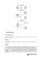
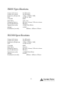
Clever Features, Contractor Friendly
IS600
IS1200
Stereo Professional Audio Amplifiers
Installation
&
Operation Manual
Introduction
The Australian Monitor Installation Series IS600 & IS1200 are 2 RU stereo power
amplifiers. The IS600 delivers 300 watts per channel @ 4 ohms & the IS1200
delivers 600 watts per channel @ 4 ohms. Designed for permanent
installations where high quality audio reproduction is required on a small
budget, the IS series deliver the sound quality & features contractors require.
The IS series continues the Australian Monitor tradition of delivering an
amplifier packed with clever features at a contractor friendly price.
2
Features
•
•
•
•
•
•
•
•
•
•
•
Custom 2RU design.
High efficiency toroidal mains transformer.
Binding post and 4 pole speaker output connection.
Stereo or Parallel operation.
Balanced inputs and buffered attenuators.
Signal Present indication.
Output clip indication.
Efficient front to back cooling.
Twin speed axial fans.
Thermal fault indication.
Signal ground lift switch.
Protection Features
•
•
•
•
Short circuit protection.
Overload protection.
Soft Start.
Thermal protection.
3
Contents
1. Introduction
2. Controls, Connectors & Indicators
2.1 Front Panel
2.2 Rear Panel
3. Installation
4. Operation
5. Maintenance
6. Specifications
Page
2
5
5
7
9
11
14
15
IMPORTANT!
Please read carefully.
This operation manual contains important information regarding safety precautions,
installation, performance, operation and maintenance of your IS-Series power amplifier. You
should familiarize yourself with the contents of this manual before operating your amplifier
The user should not attempt to service the amplifier. Only qualified and knowledgeable
personnel familiar with the internal workings of the amplifier should attempt any repair,
servicing or authorized modification to the amplifier. The amplifier does not contain any parts
which the user can service or re-use in this or any other product.
If you are in need of special assistance and the information you require is outside the scope
of this manual, please contact your nearest service agent or Australian Monitor direct:
THE TECHNICAL OFFICER
AUSTRALIAN MONITOR
C/- AUDIO TELEX COMMUNICATIONS PTY LTD
PRIVATE BAG 149,
SILVERWATER. N.S.W. 1811
AUSTRALIA.
Phone
Fax
Australia
(02) 9647-1411
(02) 9748-2537
International 61-2-9647-1411 61-2-9748-2537
Email [email protected]
Internet
www.australianmonitor.com.au
4
Front Panel
1
2
3
5
4
6
1 Attenuator
There are 2 level controls on all IS models. Each control is labelled for the
channel which it controls. 0dB indicates minimum attenuation.
2 Clip Indicator
This LED displays the status of the output stage and displays two levels of
operation.
These levels are:
Below clip level
Clipping & above
(unlit)
(red)
The LED will change to red once the output exceeds the clipping point of
the amplifier’s output stage. The threshold is referred to the amplifier supply
rails and alters with changes in the mains supply, changes in the load and
duty cycle fluctuations.
The attack and decay time (ballistics) of the status circuit are those of a
Peak Programme Meter (P.P.M.)
5
NOTE: The amplifier is not damaged by running into clipping, but speakers
may be. To maximise the life of your speakers, try to keep clipping
infrequent.
3 Power Switch
This switches AC power to the amplifier. Press the switch to up for power on
and down for power off. At start-up (turn-on), the input to the amplifier is
muted for approximately two seconds.
4 Protect Indicator
This red LED will illuminate when thermal shutdown occurs.
5 Active Indicator
This LED will illuminate blue and indicates that the amplifier is ON and
receiving AC mains power.
6 Signal Indicator.
This LED displays the status of the output stage and varies in intensity in
proportion to the output signal level.
6
Rear Panel
7
13
8
9
14
10
12
11
15
7 Balanced XLR Input
A female 3-pin XLR type connector is provided for each input:
Pin 1 = Signal Ground;
Pin 2 = Hot (non-inverting or in phase);
Pin 3 = Cold (inverting or reverse phase).
8 Balanced 6.35mm TRS Input
A female 6.35mm TRS connector is provided for each input.
Tip = Hot (non-inverting or in phase);
Ring = Cold (inverting or reverse phase);
Sleeve = Signal Ground.
9 Input Sensitivity Switch
This switch allows the amplifiers input sensitivity to be correctly matched to
the
equipment providing the amplifiers input signal. See the Operation
section (page 12) for more details.
10 Parallel/Stereo Switch
This switch determines whether channels A & B are receiving separate signals
(i.e. Operating in stereo mode) or whether the input signal from channel A
is being fed through to channel B.
7
Note: This is not Bridge mode.
11 Ground Lift Switch
When this switch is engaged, it disconnects signal ground from the input
connectors on both channels. It is intended to be used when “hum” is
caused by earth loops (due to different ground potentials between source
equipment and the amplifier) or stray magnetic field pick up on the input
ground/shield wiring. The amplifier should be turned off before engaging this
switch!
12 Speaker Output Connector
A 4 pole speaker connector is provided as an additional speaker output. This
standard of loudspeaker-to-amplifier connection allows access to both
channels of the amplifier via the one connector for bi-amp applications.
Channel-A is considered the dominant channel and has both channels wired
to the speaker connector. See the installation section of this manual for
detailed information on speaker connector wiring.
13 Mains Fuse
The IS600 is fitted with a 8 amp slow blow fuse & the IS1200 is fitted with a 15
amp slow blow fuse.
14 Mains Connection
Your amplifier is fitted with an internationally recognised IEC mains inlet
connector. Please ensure that the connecting mains lead for use with the IEC
connector is of an approved type and is of sufficient current carrying
capacity.
NOTE: Your unit must always be earthed!
15 Binding Post Outputs
Touch-proof binding posts (banana jacks) are provided for speaker output
termination with banana plugs or bare wire. The red post is used as positive
and the black post is used as negative.
8
Installation
Power Requirements
Ensure that your mains voltage is the same as the rear panel mains voltage
marker (+/- 10%).
Mounting
Your amplifier is designed for standard 19” rack mounting and occupies 2 EIA
rack units.
Cooling
Each channel of your IS Series amplifier is cooled by an axial fan which draws
cool air from the front of the amplifier and expels heated air out the rear of
the amplifier. These amplifiers include two-speed fans which normally run at
half speed, switching to full speed when the internal heatsink temperature
exceeds 500C. An unrestricted airflow into and out of the amplifier must be
provided. Any restriction of the air flow will cause heat to build up within the
amplifier and possibly force the amplifier into its thermal shutdown mode. If
9
the amplifiers are to be operated in an environment where the airflow is
restricted, such as sealed racks, cooling should be supplemented by extra
cooling fans to evacuate the heated air and aid the flow of cool air through
the amplifier.
Input Wiring
IMPORTANT
Do not directly connect pin 1 on the amplifier’s input XLR or TRS jack, to the
amplifier’s chassis, speaker ground or power ground!
NOTE: Input signal ground is not to be used as a safety ground (earth).
The input to your amplifier is a balanced 3-pin configuration and requires all
three pins to be connected. Only high quality twin-core shielded cable
should be used. When wiring for a balanced source, the connector going to
the input of your amplifier should be wired as follows:
Pin 1 = GROUND / SHIELD.
Pin 2 = HOT (In Phase - non inverting).
Pin 3 = COLD (Reverse Phase - inverting).
When wiring for an unbalanced source you must ensure that pin 3 is
connected to pin 1 (input ground), either by linking the pins in the input
connector or by the source equipment’s output wiring.
When wiring for an unbalanced source:
Pin 1 = GROUND/SHIELD
Pin 2 = HOT (in phase with the amplifier’s output),
Pin 3 = GROUND/SHIELD (joins to pin 1).
NOTE:
In-line XLR connectors often have a termination lug that connects directly to
the chassis of the connector. Do not link this lug to pin 1 at the amplifier’s
input as it will defeat the amplifier’s input grounding scheme. This lug is often
referred to as a ”drain” and is used to provide a termination to the chassis for
shielding purposes when a floating signal ground is required between the
source and destination, or when disconnecting the signal ground is required
to reduce earth loop noise, or noise induced into signal grounds from stray
magnetic fields.
Output Wiring
When wiring to your speakers, always use the largest gauge wire your
connector will accept. The longer the speaker lead, the greater the losses will
be, resulting in reduced power and less damping at the load. We
recommend using a heavy-duty, two core flex (four core flex if bi-amping) 10
to 12 gauge (2mm2 to 2.5mm2 or 50/0.25 or equivalent) as a minimum.
10
Binding Post Outputs
When terminating to the 4 mm binding post (banana jack) output
connectors, banana plugs or bare wires can be used. The red terminal is
positive and the black terminal is negative (ground).
Speaker Outputs
When using the 4 pole speaker connector for speaker output, use only the
mating 4 pole in-line connector. This connector is designed so that both
speakers can be fed from a single connector. Two speaker connectors are
provided on the amplifier. The ”Channel A” speaker connector actually
carries both channel A & Channel B outputs (see: Speaker Connector Wiring
Diagrams). The ”Channel B” speaker connector carries the Channel B output
only. This arrangement allows you the option of connecting to the outputs
separately or together. Connecting through a single connector has the
advantage of minimising connections, preserving phasing and simplifying
channel allocation, which is particularly important when bi-amping.
IMPORTANT
Do not overload your amplifier by connecting the channel B output twice!
Channel A is used as the “dominant” channel and when sourcing a dual
output from Channel A, the following standard should be used:
Channel A = Left or Low Frequencies.
Channel B = Right or High Frequencies.
Operation
IMPORTANT
All signal source equipment should be adequately earthed. This not only
ensures your safety, but everybody else’s as well. Faults can and do occur in
mains connected equipment where the chassis can become “live” if it is not
properly earthed. In these instances, the fault in a “floating” (ungrounded)
piece of equipment will look for the shortest path to ground, which could
possibly be your amplifier’s input. If the fault current is large enough, it will
destroy the input to your amplifier and look for the next available path, which
may be you!
11
Before making any connections to your IS Series amplifier, observe the
following:
Ensure the mains voltage supply matches the label on the rear panel of
your amplifier (+/- 10%).
Ensure that the power switch is OFF.
Ensure that all system grounds (earth) are connected from a common
point. Avoid powering equipment within a system from multiple power
sources that may be separated by large distances.
Check the continuity of all interconnecting leads to your amplifier; ensure
that there are no open or short circuited conductors.
Ensure that the power handling of your load (speakers) can adequately
cope with the power output of the amplifier.
Before operating your IS Series amplifier, ensure that:
- The attenuators are at the “OFF” position (fully anticlockwise).
- The GROUND LIFT Switch is not engaged (should be in the “Ground”
position).
Powering Up
REMEMBER
The amplifier should be the last piece of equipment that you turn on and the
first piece of equipment that you turn off.
We recommend turning the attenuators on your amplifier down when turning
the unit on. When you power up your IS Series, your amplifier goes through an
initialising period before it will accept signal. The Inrush Current Suppression
(ICS) circuit is in operation for the first 0.5 seconds. This limits the mains current,
to prevent ”nuisance-tripping” of circuit breakers. During this period you will
hear a couple of relays “click”, indicating mains is now directly applied to the
amplifier and the signal path is connected. While the ICS circuit operates
there is also a 30dB mute on the signal input. After two seconds this mute will
release, allowing any applied signal to pass un-attenuated. When switching
the amplifier off, wait a couple of seconds before switching the amplifier on
again. This allows the ICS circuit to reset.
Level Matching
The normal operating position for the attenuator is the maximum position
(fully clockwise, no attenuation). In this position the amplifier operates at full
gain. Turning the attenuator down (anticlockwise) reduces the input
sensitivity.
NOTE:
If full power output is required, you should operate your amplifier with the
front panel attenuator above the half way (12o’clock) position, otherwise
clipping of the input circuitry (and its resultant distortion) will occur before full
output power is achieved.
12
Sensitivity
Your amplifier is a linear device operating with a fixed input to output voltage
gain (less attenuation). The maximum output voltage swing is determined by
the applied mains voltage, load, load type and the duty cycle of the
applied signal. The input sensitivity for your IS Series amplifier when the
attenuator is at maximum position (fully clockwise) is determined by the Input
Sensitivity switch.
There are 3 settings for rated power into a 4 ohm load.
0.775V in for rated power out
1.0V in for rated power out
1.44 V in for rated power out.
Each channel of your IS Series amplifier has a nominal balanced input
impedance of 20kOhms (@1kHz) and should not present a difficult load for
any signal source. (i.e. the equipment feeding signal).
Hum Problems
Most equipment is designed for minimum hum when used under ideal
conditions. When connected to other equipment and to a safety earth in an
electrically noisy environment, problems may occur. The three ”E”s of hum
and hum related noise which can plague your audio system are:
a) Electrostatic radiation,
b) Electromagnetic radiation, and
c) Earth loops
Electrostatic radiation capacitively couples to system elements, causing an
interference voltage that mainly affects higher impedance paths, such as
amplifier inputs. The source is generally a nearby high voltage, such as a
mains lead or a speaker lead. The problem can usually be reduced by
moving the offending lead away, or by providing additional electrostatic
shielding (i.e. an earthed conductor which forms a barrier to the field).
Electromagnetic radiation induces interference currents into system elements
that mainly effect lower impedance paths. Radio transmitters or stray
magnetic fields from mains transformers are often the cause of this problem.
It is generally more difficult to eliminate this kind of interference, but again,
moving the source away or providing a magnetic shield (i.e. a steel shield)
should help.
13
Earth loops can arise from the connection of the various pieces of equipment
and their connections to various safety earths. This is by far the most common
cause of hum and it occurs when source equipment and the amplifier are
plugged into different points along the safety earth where the safety earth
wiring has a current flowing through it. The current flowing through the wire
produces a voltage drop due to the wire’s resistance. This voltage difference
between the amp earth and source equipment earth appears to the
amplifier’s input as a signal and is amplified as hum.
There are three things you can do to avoid earth loop problems:
1. Ensure the mains power for the audio system is “quiet” i.e. without
equipment on it such as air-conditioning, refrigeration or lighting which
may generate noise in the earth circuit.
2. Ensure all equipment within the system shares a common ground/ safety
earth point. This will reduce the possibility of circulating earth currents, as
the equipment will be referenced to the same ground potential.
3. Ensure that balanced signal leads connecting to the amplifier are
connected to earth at one end only.
Signal Ground-Lift Switch
When proper system hook-up has been made, you may still have some hum
or hum related noise. This may be due to any of the previously mentioned
gremlins. Your IS Series amplifier has a “Signal Ground Lift” switch which
disconnects the input ground wiring from the amplifier. A substantial drop in
hum and/or hum related noise can result from the judicious use of this switch.
NOTE:
If the input ground lift switch is used, you must ensure adequate shielding of
the input wiring. If the signal source equipment does not provide adequate
shielding (i.e. a definitive connection to ground), you must disconnect the
shield from the input connector’s ground pin (Pin-1) and re-connect it to the
”drain” contact on the input connector. This will ensure the shield on your
input wiring actually goes to the amplifier chassis and subsequently to earth.
DO NOT CONNECT PIN-1 DIRECTLY TO THE DRAIN CONNECTION.
You will defeat the amplifiers internal grounding scheme and possibly cause
instability in the amplifier. Always ensure that your amplifier is off and the
attenuators are down when you engage this switch. This switch should only
be used when the amplifier is operated from a balanced signal source.
NOTE:
Be wary of quasi-balanced outputs, these are often no more than floating
unbalanced outputs.
14
Maintenance
Only competent qualified persons should attempt any service or
maintenance of your amplifier. Your IS Series amplifier will need
minimal maintenance. No internal adjustments need to be made to
the unit to maintain optimum performance. To provide years of unhindered
operation we suggest a maintenance inspection be carried out on a regular
basis, say every 12 months or so.
NOTE;
The following instructions are intended for action by qualified personnel only.
Fans
Due to the openness of the air path through your IS Series amplifier, very little
dust should settle within the amplifier. The unit has been designed so that any
dust and/or foreign particles that do settle within the amplifier will not unduly
hinder the cooling of the amplifier. The grille in front of the fans will act to limit
the amount of dust and lint entering the amplifier. You will find that in time
there will be a build up of dust and lint on the grille which may hinder the
airflow through the amplifier. You should periodically remove the dust and
keep the grille clean. Removal of dust from the rear grille will also aid cooling.
Over time, dust may build up on the leading edge of the fan blades and
reduce their cooling efficiency. The time taken for this to happen will depend
on the environment and the amount of use. The fan blades are accessible
once the lids are removed and can be easily cleaned. You need only hold
the fan rotor still and wipe the dust off the blades. Many users stall the fan
and use compressed air to blow the dust off the fan blades. It is important to
note that the fan blades must be held still whilst blowing air over the blades
otherwise you may burn out the bearings in the fan.
Fuses
Along with a rear panel mains fuse, there are four (4) internal rail fuses in the
unit. These rail fuses are in series with the positive and negative output supply
to each amplifier channel and provide overall protection for the output
stage. If the amplifier is subjected to heavy use such as short circuits, these
fuses will eventually fatigue and may require replacing to ensure they do not
fail at an inconvenient time.
NOTE
Make sure the unit is off and is unplugged from the mains. Give the
main filter capacitors time to discharge before removing lids and
inspecting the fuses.
You should replace the fuse if the element is sagging or discoloured. Only
ever replace with the same type fuse and current rating.
When checking for a failed fuse, do not rely on visual inspection alone. You
should use an ohm meter to check continuity.
15
IS600 Specifications
Output @ 8 ohms
Output @ 4 ohms
Frequency Response
THD
Crosstalk
Slew Rate
Damping Factor
Input Impedance
Signal/noise ratio
Weight
Dimensions (wxdxh)
2 x 200 watts
2 x 300 watts
<10Hz - >50kHz (-3dB)
<0.03% @1 kHz
60dB
12.5 v/ms
250 into 8 ohms/ 125 into 4 ohms
20Kohm
>99dB 20Hz-20kHz
16.5KG
483mm x 452mm x 89mm
IS1200 Specifications
Output @ 8 ohms
Output @ 4 ohms
Frequency Response
THD
Crosstalk
Slew Rate
Damping Factor
Input Impedance
Signal/noise ratio
Weight
Dimensions (wxdxh)
2 x 400 watts
2 x 600 watts
<10Hz - >50kHz (-3dB)
<0.03% @1kHz
60dB
12 v/ms
250 into 8 ohms/ 125 into 4 ohms
20Kohm
>105dB 20Hz-20kHz
20.5KG
483mm x 452mm x 89mm
16
17