1
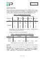
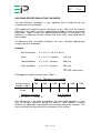
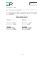
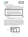
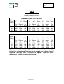
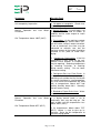
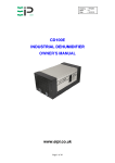
Drawing : - TPC229
Issue
:-2
Date
: - 10/12/13
LUMBER DRYER
LD3000
OWNER’S MANUAL
www.eipl.co.uk
Page 1 of 40
Drawing : - TPC229
Issue
:-2
Date
: - 10/12/13
INTRODUCTION
You have probably never seriously considered kiln drying your own lumber
before, believing it to be too expensive or too complicated to undertake on a
small scale.
Prior to the introduction of the Ebac Small Scale Lumber Dryers this was true.
Kiln drying was for the world of specialists: a confusing maze of kiln
schedules, sampling techniques, relative humidity’s and complex controls –
hardly inviting to the small woodworking business which merely wanted to be
sure of a regular supply of quality wood at a reliable and consistent moisture
content.
Ebac Small Scale Lumber Dryers have changed all that. Whether yours is a
one-man business or somewhat larger, whether you are in the woodworking
business or woodworking is just your hobby, you do not need any previous
experience with drying. As well as being simple to install and operate, Ebac
dryers are quiet and cause no pollution.
The Lumber Dryers themselves are installed in easily made chambers of the
appropriate size.
This manual has been designed to guide you through the problems of
choosing the correct size of wood dryer for your needs, constructing a suitable
chamber and operating the kiln to obtain maximum output of wood.
Use it carefully and thoroughly and you will quickly find out everything that you
need to know.
For further information and details of constructions and applications not
covered, we will be pleased to offer advice and assistance as required.
Please do not hesitate to contact us.
Page 2 of 40
Drawing : - TPC229
Issue
:-2
Date
: - 10/12/13
SIMPLIFIED SCHEMATIC DIAGRAM OF LUMBER
COMPONENTS
Figure 2
Though the fastest drying is achieved at high temperature, the risks of
degrade in the wood, particularly hardwood, increases at high temperature.
The general rule is that the lower the temperature the better the quality.
Ebac dryers are designed to operate in the temperature range, which is the
best compromise between speed and quality – about 140°F (60°C) and lower.
Drying at these temperatures insures that the wood is of the highest quality,
and that the equipment is reliable.
Page 3 of 40
Drawing : - TPC229
Issue
:-2
Date
: - 10/12/13
UNPACKING
Upon receipt of your LD3000, carefully inspect the shipping container and its
contents for any damage. If damage is discovered, contact the Service
Department for instructions.
CONTENTS
Your LD3000 shipment consists of the following items:
1.
2.
3.
4.
5.
LD3000 Lumber Dryer with Power Cord
Discharge Hose
STC1 Controller
(2) Wall Mounting Brackets
(2) 16 – inch Circulation Fans
Page 4 of 40
Drawing : - TPC229
Issue
:-2
Date
: - 10/12/13
DRYER CAPACITIES
Table 1 below shows average drying times for the LD3000. Table 2 shows
the optimum load capacities for the LD3000. If larger quantities than those
shown in Table 2 are dried, drying speed will be proportionately slower. If
small quantities are dried, the controls can be adjusted to allow for this.
Table 1 – Average Dying Times in Days*
MOISTURE CONTENT RANGE
FROM – TO
50% - 8%
405 – 8%
30% - 8%
20% - 8%
Type
Hardwoods**
Thickness
1”
2”
3”
Days
50
90
158
Days
37
68
119
Days
25
45
81
Days
13
25
43
Softwoods
1”
2”
3”
14
32
53
10
25
40
6
15
27
4
8
14
*
Drying times may vary depending on species, starting moisture
content, thickness, and size of load.
**
Drying of Claro Walnut is not recommended.
Table 2 – Optimum Lumber Capacities in Board Feet
Lumber Type
Softwoods
Hardwoods
Thickness
(Inches)
1”
2”
3”
1”
2”
3”
LD3000
1440
3210
5400
3000
5150
8875
(Some capacities can be smaller or larger – consult Ebac)
Example 1: You wish to dry 4/4 Oak from a starting moisture content 30% to
8%.
From Table 1, you see that it will take 25 days to dry 4/4 (1”) hardwood for
30% to 8%.
Then from Table 2, the optimum capacity for 1” hardwood fro the LD3000 is
3000BF. Therefore, 3,000BF can be dried in about 25 days, and 42,000BF in
a year. (365/25 days = 14 loads per year x 3,000BF per load).
Page 5 of 40
Drawing : - TPC229
Issue
:-2
Date
: - 10/12/13
KILN CHAMBER
LUMBER STACK SIZE
The first step in determining your kiln chamber size is to determine the most
suitable lumber stack size (or configuration) for your purposes. This will
depend primarily on the longest length board to be dried. Normally, the length
of the stacks will be equal to the length of the longest board. If you lumber is
in short lengths (i.e.: approximately 3 feet), then the stack length should be
multiples of these lengths.
The width and height of the stack can be adjusted to suit your conditions. The
“stack” may actually be made up of two or more smaller stacks, or packs.
In order to allow air-flow through the lumber stack, each “layer” must be
separated from the below by a spacer or “sticker” of ¾ to 1” thickness. The
air spaces thus created must be included in the overall stack height when
calculating volume.
Use this procedure to determine stack height and width: First select an
appropriate width and then calculate stack height including stickers. If this
calculated height would result in an awkward height to width, select a new
width. See example 2 which follows.
Example 2: Desired kiln capacity is 3,000BF of 1” hardwood, and the longest
board is 16 feet. Add 10% to the lumber quantity to allow for non-uniformity in
the stack. If that stack width is 6 feet, then each layer of lumber would
contain:
BF per layer = 16’ x 6’ x 1” thick = 96BF
Layers required = 3,000BF x 1.1 = 34.4 of 35 layers
96BF/layer
Each layer is 1” ¾” sticker = 1 ¾“ high
Stack height = 35 layers x 1 ¾” high = 61 ¼” high (rounded up to 5 ¼’)
Thus, the stack size is:
16’ long x 6’ wide and 5 ¼’ high
Page 6 of 40
Drawing : - TPC229
Issue
:-2
Date
: - 10/12/13
CHAMBER INTERIOR DIMENSIONS
Having calculated the stack size, it is now possible to calculate the
appropriate internal dimensions of the chamber. This is done by adding the
required additional space around the stack for the dryer and the fans as well
as for good air circulation. Suggested additional space is:
Length:
1’
Width:
2 ½’
Height:
2’
Example 3: Using the information from Example 2, where the stack size is
16’ long and 6’ wide and 5 ¼’ high, we can find the required internal
dimensions.
Length:
16’ + 1’ = 17’
Width:
6’ + 2 ½’ = 8 ½’
Height:
5 ¼’ + 2’ = 7 ¼’
Page 7 of 40
Drawing : - TPC229
Issue
:-2
Date
: - 10/12/13
CHOOSING PROPER INSULATION THICKNESS
The wall thickness (insulation) is very important and is related to the size
(surface area) of the chamber.
After adding the required internal clearances to the stack size, the internal
dimensions are known, and the approximate chamber surface area can be
calculated. Table 3 shows the recommended thickness of insulation (wall
thickness) in relation to the total surface area of the walls, ceiling and floor of
the chamber.
To determine wall (insulation) thickness we must calculate approximate
surface area of the chamber.
Example:
Kiln Dimensions:
8 ½’ x 8 ½’ x 18’ (H x W x L)
Ends:
8 ½’ x 8 ½’ x 2 pieces
145 sq.ft
Top and Bottom:
8 ½’ x 18’ x 2 pieces
306 sq.ft
Front and Back:
8 ½’ x 18’ x 2 pieces
306 sq.ft
_______
757 sq.ft surface area
Pick proper insulation thickness from Table 3.
Table 3 – Thickness of Insulation
Surface Area of
Camber in Sq.Ft
Optimum RValue
500
800
1100
1400
1800
2100
11
16
19
19
21
21
Fiberglass Insulation
R-11 = 3 ½”
R-19 – 6”
Blue Styrofoam
R-7 = 1”
The thicknesses in the table are optimum for year round operation. If you
wish to increase efficiency during the winter in cold climates, increase
thickness by about 50% and remove extra insulation during the summer. This
extra insulation may cause the kiln to overheat in the summer.
Page 8 of 40
Drawing : - TPC229
Issue
:-2
Date
: - 10/12/13
EXAMPLE KILN SIZES
If you would rather not design the dimensions of you kiln, simply choose the
best size for you operation from Table 4.
All of the kiln dimensions shown are exterior dimensions. The load sizes refer
to 1” hardwood with ¾” stickers, and all the wall thickness and air spaces
have been added in.
Table 4 – Example Kiln Sizes
(Height x Width x Length)
6’ Lumber
2 Stacks – See 12’ Lumber
8’ Lumber
2 Stacks – See 16’ Lumber
10’ Lumber
10 x 10 x 12 = 3000BF
10 x 9 ½ x 12 = 2700BF
9 ½ x 9 ½ x 12 = 2500BF
12’ Lumber
9 ½ x 9 ½ x 14 = 3000BF
9 ½ x 9 x 14 = 2700BF
9 x 9 x 14 = 2500BF
14’ Lumber
9 x 9 x 16 = 3000BF
9 x 8 ½ x 16 = 2700BF
8 ½ x 8 ½ x 16 = 2500BF
16’ Lumber
8 ½ x 8 ½ - 18 = 3000BF
8 ½ x 8 x 18 = 2700BF
8 x 8 x 18 = 2500BF
Page 9 of 40
Drawing : - TPC229
Issue
:-2
Date
: - 10/12/13
CONSTRUCTION OF CHAMBER
Floor:
An insulated concrete floor is recommended.
•
•
•
•
Notes:
Start with a gravel base.
Lay down 2” of rigid Styrofoam.
Pour 4” of reinforced concrete.
Seal concrete with any commercially prepared sealer
A slightly pitched floor leading to drain may be incorporated.
This will helpful if large amounts of softwood are to e dried.
Should an insulated concrete floor not be feasible, a well-built,
insulated wooden floor will work.
See Figure 3.
Wall/Ceiling Construction:
•
•
•
•
•
•
•
•
Make a 2” x 4” studded frame.
Cover exterior with ½” exterior grade plywood or waferboard.
Insulate to proper R-Value.
Staple or tack 4mm. Plastic over insulation prior to installing inside the
wall. This vapor barrier protects insulation from moisture.
Spray paint over staples to prevent corrosion.
Hand ¼” exterior grade plywood as inside wall.
Coat the inside wall and ceilings with a vapor barrier grade sealer.
This protects the inside walls and ceiling from moisture and insures
long life for your kiln. (Aluminized mobile home roofing paint works
well).
Use a silicone caulk to seal up all cracks and seams.
See Figures 4 and 5.
Page 10 of 40
Drawing : - TPC229
Issue
:-2
Date
: - 10/12/13
Door Construction:
•
•
•
The door section should be constructed the same as the walls and
ceiling.
Exterior plywood should overlap the door frame by 3”. This will allow
space to attach a rubber gasket and enable the door to be bolted to the
kiln chamber. Anchor bolts are recommended for continued usage.
For front loading kilns, hinged double doors are needed.
See Figures 6 and 7.
Fan Truss:
The LD3000 kiln accomplishes air circulation with the aid of two (2)
supplemental overhead fans. The 110 Volt, 60 Hz fans are wired in separate
from the drying unit.
•
•
•
•
•
•
•
The fan truss, which hangs from the ceiling, should run the length of
the kiln.
The truss should be located 18” from the front of the drying unit.
The truss should be framed with 2” x 42 studs.
The circulation fans should be evenly positioned within the truss.
Air flow should move away from the dryer.
Plywood or waferboard is used to cover the open area of the fan truss.
For all dry kiln, baffles or curtains should be used above and to the side
of the stack to force the air flow through the lumber stack, not around it.
Heavy plastic is the most common baffling.
See Figure 8.
Material List:
1.
2.
3.
4.
5.
6.
(Numbers correspond with drawings)
¼” or ½” CDX plywood or article board.
4mil. Poly under CDX plywood or particle board.
Fiberglass or Blue Styrofoam insulation.
Fiberglass or Blue Styrofoam insulation.
2” x 4” or 2” x 6” Construction.
Rubber Gasket (Garage door seal works well).
Page 11 of 40
Drawing : - TPC229
Issue
:-2
Date
: - 10/12/13
Page 12 of 40
Drawing : - TPC229
Issue
:-2
Date
: - 10/12/13
Page 13 of 40
Drawing : - TPC229
Issue
:-2
Date
: - 10/12/13
Page 14 of 40
Drawing : - TPC229
Issue
:-2
Date
: - 10/12/13
Page 15 of 40
Drawing : - TPC229
Issue
:-2
Date
: - 10/12/13
Page 16 of 40
Drawing : - TPC229
Issue
:-2
Date
: - 10/12/13
Page 17 of 40
Drawing : - TPC229
Issue
:-2
Date
: - 10/12/13
INSTALLATION AND TESTING
Installation
All wiring should be carried out by a competent electrical contractor in
accordance with local regulations.
The 16-inch circulation fans do not connect to the STC1 Controller. They
must be connected to separate switchgear.
Warning:
OSHA complying guards are strongly recommended
when fans are installed with 7’ of floor, working level,
or within reach of personnel. Review OSHA codes.
Check the voltage at the power supply to insure correct voltage is 220 Volt +/10%, 1 Phase, 60 Hz.
The LD3000 must be plugged into a suitable fused 220 Volt outlet.
Using the mounting brackets provided with the unit, mount the LD3000 4” – 8”
from the ceiling, centered on the back wall.
Attach the discharge hose to the drainage nipple.
Locate and drill three (3) holes fro the following:
Discharge hose – ensure that the water discharge will gravity feed from
the kiln chamber.
Power cord and Controller cord – Ensure that the power cord reaches
the 220 Volt, 1 Phase, 60 Hz outlet and that the controller cord reaches
the plug connection on the STC1 Controller.
Use silicone rubber caulking or a similar material to seal the holes after proper
installation of the discharge hose, power cord, and controller cord. This will
aid in preventing heat loss from the kiln.
Page 18 of 40
Drawing : - TPC229
Issue
:-2
Date
: - 10/12/13
TESTING FOR PROPER INSTALLATION
Remove lower front panel by removing four retaining screws.
Warning:
Do not operate the LD3000 for an extended period of time
with the covers removed. This will cause improper operation
of the machine and may cause damage to components.
Adjust the temperature control and the drying control on the STC1 Controller
to the minimum setting.
Attach the controller cord to the STC1 Controller and latch in place.
Plug the LD3000 power cord into the 220 Volt, 1 Phase, 60 Hz receptacle.
(Insure that power to the receptacle has been achieved).
The fans in the LD3000 will start to rotate immediately. Set the STC1 drying
control to C and the temperature control to 45ºC.
The above settings will result in the following:
1. The heating element will produce heat.
2. After a 6 minute delay, the compressor will start to run.
When the compressor has been running for 6 minutes, the bare copper coils
above the draintray should be covered with either frost or condensation. (The
last two or three turns on the rear coils may not have frost or condensation
because the refrigerant is picking up superheat for the return to the
compressor).
After insuring proper operation of the LD3000, disconnect the power cord and
reinstall the lower front panel.
Page 19 of 40
Drawing : - TPC229
Issue
:-2
Date
: - 10/12/13
Page 20 of 40
Drawing : - TPC229
Issue
:-2
Date
: - 10/12/13
TESTING TWO-STAGE OVERHEAT SYSTEM
Disconnect the power cord from the receptacle. Remove the top front panel
by removing the six retaining screws. Reconnect the power cord to the
receptacle.
Warning:
DO NOT reach into the electrical panel with your hand or any
tool. This may result in a severe electrical shock or death.
Set the drying control on the STC1 Controller to C and the temperature to
45ºC.
Gradually reduce the temperature control setting. When the temperature
setting equals the temperature indicated by the temperature display, the
heater will switch of. This can be verified by observing the C1 Contactor.
When this contactor de-energizes, the heat is off. Reduce the temperature
control further and the compressor will switch off when the temperature
setting is below 5º below the temperature display. This can be verified by
observing the C2 contactor.
When this contactor de-energizes, the
compressor is off (See Figure 9).
Should you have any problems resulting from testing your LD3000 or STC1
Controller, contact the Service Department of assistance.
Page 21 of 40
Drawing : - TPC229
Issue
:-2
Date
: - 10/12/13
HIGH TEMPERATURE VENT SYSTEM
If in the event you have purchased a vent system for your LD3000 kiln, please
follow these instructions for installation and operation.
Exhaust vent fan, intake shutter motor, and thermostat should be wired by a
licensed electrician in accordance with local codes. Assembly should be
wired separately from all other Ebac equipment, to a 115 Volt, 60 Hz, 15 Amp
supply. Vent fan and shutters will engage automatically if the kiln temperature
exceeds the setting on the thermostat control.
The differential on the thermostat has been pre-set at 3ºF. This will insure
proper operation and control the desired kiln temperature.
Vent fan intake shutter cutouts are 13” square.
Both the vent fan and intake shutter should be mounted at east 3 ½ ft above
the kiln floor. Positioning on the same kiln wall or at opposite ends of the kiln
is acceptable. However, if positioned on the same wall, allow 6 feet minimum
between shutter intake and kiln wall. The exhaust shutter open to the outside,
the intake shutter open to the inside of the kiln.
Warning:
OSHA complying guards are strongly recommended
when fans are installed with 7’ of floor, working level,
or within reach of personnel. Review OSHA codes.
Adjust the vent thermostat knob accordingly as you adjust your STC1
Controller thermostat during your kiln drying run. The vent thermostat and
STC1 Controller heater thermostat should be set at the same degree. A
handy conversion chart has been included converting ºC to ºF.
CENTIGRADE
10
15
20
25
30
35
40
50
FARENHEIT
50
59
68
77
86
95
104
122
(maximum for LD3000)
Page 22 of 40
Drawing : - TPC229
Issue
:-2
Date
: - 10/12/13
DRYING LUMBER
The best lumber drying results are obtained when the loads of lumber are of
the same species, quality, thickness and initial moisture content. However,
this is not always possible, particularly in small scale operations. In such
situations the drying procedure should follow the slowest wood in the load –
i.e., the hardest, thickest, or wettest boards.
The layers of lumber are separated by stickers. The thickness or the stickers
is determined by the thickness of the lumber most commonly being dries.
Stickers or ¾” are generally used with boards up to 1 ½” thick and stickers of
1” for boards thicker than 1 ½”. In practice, one set of stickers can be used in
a kiln no matter what the lumber thickness.
The layers of stickers should be placed directly above each other to prevent
distortion of the boards during drying. The space between columns of stickers
should be approximately 18” To 30” for board thickness up to 1 ½” and 24” to
48” for board thickness’ greater than 1 ½”. Put a column of stickers at each
end of the stack to support the ends and help reduce checking. The important
consideration is that the boards do not sag between rows of stickers.
Gaps in the stack cross-section are reduced by using boards of the same
length, which otherwise would result in a non-uniform circulation at these
spots. If this is not possible, any gaps/spaces should be blocked with baffles
so that the air passes through the stack and not round it.
Before placing the lumber in the chamber, the initial moisture content of the
wettest boards should be measured by means of an electronic moisture meter
or the over dry method (see Appendix 1). Ebac can provide a suitable
moisture meter system to meet your needs at an additional cost.
Page 23 of 40
Drawing : - TPC229
Issue
:-2
Date
: - 10/12/13
KILN OPERATING INSTRUCTIONS
1. Connect the main power cable to a suitable power supply.
2. Select the appropriate setting from the relevant drying control schedule
as shown in table 5. Settings are based on the amount and type of
lumber to be dried.
Warning: If the Table calls for a setting of “C” (Continuous), set the
drying control at 90% at first, until the temperature reaches
38ºC (100ºF). Position “C” can them be selected.
Below 38ºC the dehumidifier requires the 10% off-time to
defrost the ice formed on the heat exchanger (cold coil).
Above 38ºC (100ºF), the condensation does not freeze, but
drips continuously into the drain tray and out through the
drainage hose.
3. Set the temperature control knob on the STC1 Controller at the lower
of the following:
A. 5ºC higher than the kiln temperature (shown on the digital
display on the controller); or
B. The maximum chamber temperature from the graph below.
The temperature should be increased by 5ºC (9ºF) every 24 hours, but must
NEVER exceed the temperatures shown on graph below. If the temperature
does not increase in accordance with the temperature control knob
adjustments. (i.e., 24 hours after an increase of 5ºC the temperature has risen
by a lower amount, e.g. 3ºC), this indicates that the heater is operating
continuously but the temperature rise has not been achieved. This can be
caused by the volume of wood being heated, cold weather conditions, or
inadequate insulation. The next temperature setting should be 5ºC above the
kiln temperature as displayed on the temperature meter.
50
45
40
Temperature
ºC
35
30
40%
30%
20%
Moisture Content of Wood
Page 24 of 40
10%
Drawing : - TPC229
Issue
:-2
Date
: - 10/12/13
Two things are very important:
A. THE RATE OF TEMPERATURE INCREASE MUST NOT BE
MORE THAN 5ºC (9ºF) PER DAY.
Never set the thermostat more than 5ºC (9ºF) above the present
kiln temperature.
Rapid temperature increases cause the relative humidity to
suddenly drop leading to surface and end checking of the
lumber.
A. THE KILN TEMPERATURE MUST NOT EXCEED THAT
WHICH IS SAFE FOR THE MOISTURE CONTENT OF THE
LUMBER.
The maximum chamber temperature, shown on the preceding
graph, indicates the maximum safe kiln temperature at every
stage of drying.
The temperature graph implies that you must measure the
lumber moisture content each time before increasing the
temperature when operating above 35ºC (95ºF). to determine if
drying cycle is complete, the lumber moisture content must be
actually measured using a moisture meter or the oven dry
method.
4. To check that the drying rate is correct, allow the kiln about 3 days to
stabilize after starting and then measure the water extracted during a
24-hour period. As the wood dries, the drying control and thermostat
may be increased to maintain the water extraction rate.
Completing The Run: When the drying cycle is complete, leave the wood for
approximately 24 hours in the chamber with the Drying Control setting
reduced to 10% and the thermostat reduced to its lowest setting. This will
allow the residual moisture within the wood to become more evenly
distributed.
Page 25 of 40
Drawing : - TPC229
Issue
:-2
Date
: - 10/12/13
Table 5
Drying Control Settings
LD3000 LUMBER DRYER
CHAMBER LOAD – SOFT WOODS
Drying
Control
Setting
C
85
65
40
1”
4/4
25mm
2”
8/4
50mm
3”
12/4
75mm
Cu
Ft
120
102
78
48
Board
Ft
440
1224
936
576
Cu
Mtrs
3.4
2.9
2.2
1.4
Cu
Ft
270
229
175
108
Board
Ft
3240
2754
2106
1296
Cu
Mtrs
7.7
6.5
5.0
3.1
Cu
Ft
450
382
292
180
Board
Ft
5400
4590
3510
2160
Cu
Mtrs
12.8
10.9
8.3
5.1
CHAMBER LOAD – HARD WOODS
Drying
Control
Setting
C
85
65
40
1”
4/4
25mm
2”
8/4
50mm
3”
12/4
75mm
Cu
Ft
250
212
162
100
Board
Ft
3000
2550
1950
1200
Cu
Mtrs
7.4
6.0
4.6
2.8
Cu
Ft
429
364
278
171
Board
Ft
5150
4377
3347
2060
Cu
Mtrs
12.2
10.4
7.9
4.9
Cu
Ft
739
628
480
295
Board
Ft
8875
7543
5768
3550
Cu
Mtrs
21.1
17.9
13.7
8.4
The above control settings will produce dried wood of good quality,
higher than recommended settings can be used to give quicker drying if
required. This may result in instances of degrade. If you are in any
doubt select only the recommended setting.
Page 26 of 40
Drawing : - TPC229
Issue
:-2
Date
: - 10/12/13
Additional Notes on Lumber Drying
As the wood dries, the daily volume of water extracted may decrease. The
drying control setting may be increased to compensate for this fall-off in order
to achieve a constant daily extraction of water.
When drying a mixture of thickness and/or species of wood, adjust the drying
control to the setting applicable for the total load of wood as if it were
comprised of the thickness or species requiring the lowest setting. E.g., a
mixture of:
1000 BF of 1” Oak and
2000 BF of 3” Spruce
3000 BF (1000 + 2000) of 1” Oak requires a setting of “C”
3000 BF of 3” Spruce requires a setting of 65%
Therefore the correct setting for the mixed load is 65%
To prevent overheating during hot weather conditions, particularly if the frying
chamber has been very well insulated, water extraction may occasionally be
suspended to enable the chamber to cool. This is not a fault condition,
however it is an indication that the chamber walls incorporate excessive
insulation. This situation can be diagnosed by observing intermittent water
extraction when the drying control is set to “C”.
In accordance with International practices, temperatures in these instructions
are expressed in degrees centigrade (Celsius). The following scale can be
used to determine the equivalent temperature in Fahrenheit.
ºC
ºF
25
77
30
86
35
95
40
104
45
113
Page 27 of 40
50
122
CENTIGRADE
FAHRENHEIT
Drawing : - TPC229
Issue
:-2
Date
: - 10/12/13
Appendix I
Oven Drying Method for Determining Equilibrium Moisture Content
If an accurate moisture meter is not available, then moisture content can be
determined using the oven dry method. The oven dry method is actually more
accurate than moisture meters, but not very convenient. You do need and
accurate scale for weighing the wood samples and an oven (a baking oven
will do) to bake the samples.
Select a plank from the wood to be dried and cut 6 inches from each end and
discard these cutoffs. (They will be much drier than the rest of the piece).
Cut several one-inch pieces from one end until you have about a pound in
weight. Weigh these and record the wet weight. Weigh the remaining portion
of the plank and add it to the middle of the lumber stack in the kiln where it
can be retrieved periodically to monitor equilibrium.
Place the 1” sample in a 225ºF oven for 24 to 36 hours then weigh again.
This is the oven dry weight. Use the formula below to calculate the starting
EMC of the sample.
EMC =
Wet Weight - Dry Weight
Dry Weight
x 100%
The moisture content of the lumber in the stack can now easily be monitored
by periodically pulling the sample from the stack and weighing it. First,
however, calculate the future dry weight of the plank by using the EMC just
calculated.
Plank Dry Weight
=
Wet Weight
1 + EMC
100
Now having calculated the plank dry weight, use the formula above for
determining EMC to monitor drying progress.
Page 28 of 40
Drawing : - TPC229
Issue
:-2
Date
: - 10/12/13
Example
You have weighed you 1” samples and they weigh 1.35 lbs. The remaining
plank weighs 15.4 lbs and is added to the lumber stack in the kiln and the
dryer can be turned on. After drying the samples 36 hours in an over, you
weigh them and the weight is 0.94 lb.
Starting EMC
=
1.35lb. – 0.94lb.
0.94lb.
x
100
= 44%
Now calculate the future dry weight of the plank in the kiln:
Plank Dry Weight
=
15.4
1 + 44
100
= 10.7lb.
After a few weeks of drying, the plank is removed from the stack and weighs
12.2lb.
Starting EMC
=
12.2lb. – 10.7lb.
Page 29 of 40
x
100
= 14%
Drawing : - TPC229
Issue
:-2
Date
: - 10/12/13
Appendix II
Troubleshooting
In case of trouble, first check that all instructions in the manual have been
carefully followed. Next, go through the following chart. If the problem is still
not resolved, call Ebac Industrial Products Ltd. In most cases, a simple
phone call will resolve the question.
System Overview
Air is drawn into the dryer where the moisture is extracted from it. Moisture is
extracted when the air is passed through the evaporator coil. The coil is
cooled to a temperature lower than dew point temperature of the air and
hence condensation forms on it.
The dryer consists of 7 parts:
1. Fan motor draws the air through the unit.
2. Compressor which drives the refrigeration circuit.
3. Evaporator coil – cold section of the refrigeration circuit.
4. Condenser Coil – hot section of the refrigeration circuit.
5. Capillary tube – separates the hot and cold section of the refrigeration
circuit with regard to gas flow.
6. Auxiliary heater.
The STC1 Controller controls the power to the dryer and controls the amount
of water to be extracted by operating the compressor in accordance with the
drying control setting, i.e. : a 25% setting will run the compressor for 15
minutes in each hour. The fan runs continuously regardless of the drying
control setting. The auxiliary heater runs only when the thermostat setting is
greater than the kiln temperature, once the desired temperature is achieved,
the heater shuts off.
Page 30 of 40
Drawing : - TPC229
Issue
:-2
Date
: - 10/12/13
Symptoms
Possible Fault
Unit completely inoperative
1. No power at receptacle. Check fuse,
etc., feeding receptacle
Normal Operation
Extraction
but
Low
Water 1. Normal Start-UP. It usually takes 3 to
4 days for a new load of lumber to
stabilize and for water output to reach
normal levels
Kiln Temperature above 100ºF (38ºC)
2. Dry Lumber. As the moisture content
of the lumber drops below about 10%,
you will notice a drop in water extraction.
If not at continuous the timer may be
advanced to maintain rate, but the
moisture content of the lumber should be
checked at this point to avoid overdrying.
3. Compressor Overheating. If the kiln
temperature is over rating for the unit,
thermal circuit breaker in compressor
may be opening. Reducing temperature
by removing insulation, or lowering
drying control setting. Do not lower
thermostat setting.
4. Refrigerant Gas Loss From Circuit. A
refrigerant loss can be recognized by
operating unit outside the kiln and check
for severe freezing of a small proportion,
less than half of the evaporator coil (cold
coil) at temperatures above 68ºF and
relative humidity above 30%. Normally
the coil freezes evenly.
5. Blocked or Frozen Drain Hose. Water
may be flooding kiln.
Normal Operation
Extraction
but
Low
Water 1. If drying control knob is set at
continuous, coils may be icing up. Set
back to 90% until the temperature rises
above 100ºF (38ºC).
Kiln Temperature Below 95ºF (35ºC)
2. At temperatures below about 75ºF
(35ºC), lumber is slow to give up its
moisture. Raise the kiln temperature to
maintain drying speed.
Page 31 of 40
Drawing : - TPC229
Issue
:-2
Date
: - 10/12/13
Symptoms
Possible Fault
Low Kiln Temperature
Normal Water Extraction
1. As long as water extraction is normal,
kiln temperature cannot be too low. In
fact, the lower the temperature the better
the wood quality.
The insulation
thickness’ in Table 1 provides for 50ºF
(28ºC) temperature rise over the outside
temperature at continuous drying control
setting. Lower settings will give lower
temperature rise.
Mold or Mildew on Lumber
1. This condition is not harmful to the
lumber, but can be minimized with
improved
airflow
or
higher
kiln
temperature.
Bottom Layer or Two of Lumber Not Dry
1. This is caused by large temperature
differences (greater than 5ºF) from top to
bottom of the kiln. Greater airflow or a
better door seal will usually improve this.
Temperature in Kiln Continues to Rise **DO NOT
Above Thermostat Setting
SETTING**
LOWER
THERMOSTAT
1. Thermometer on controller may need
to be adjusted. If extraction maintains at
normal rate, check temperature in the
kiln with thermometer at the base of the
dryer. If the temperature reads lower or
higher than the thermometer needle on
the controller, call Ebac for adjustment
procedure.
2. If temperature reads the same and
extraction ceases or slows substantially,
you may have a “temporary overinsulation situation”. Simply peel back a
corner of insulation from the top of you
kiln chamber. If this does not remedy
the situation in 24 hours, call Ebac.
Page 32 of 40
Drawing : - TPC229
Issue
:-2
Date
: - 10/12/13
Appendix III
Drawings and Specifications
Page 33 of 40
Drawing : - TPC229
Issue
:-2
Date
: - 10/12/13
LD3000 SPECIFICATIONS
Height:
33”
Width:
43”
Depth:
12”
Weight:
167lbs
Airflow:
600 CFM
Power Rating (Dryer):
1100W (Max)
Power Rating (Heater):
1500W (Operates Intermittently)
Power Supply:
208/203V, 60Hz, 1 Phase. 12 Amps
Maximum Operating
Temperature:
50ºC (122ºF)
Finish:
Epoxy/Vinyl Coated Steel
Refrigerant Type:
R22
Refrigerant Charge:
1 lb. 6oz.
Special Features:
Stainless Steel Water Collection
Tray for Corrosion Resistance
Page 34 of 40
Drawing : - TPC229
Issue
:-2
Date
: - 10/12/13
SPARE PARTS LIST LD3000
DESCRIPTION
EBAC PART NO.
QUANTITY
1. Drain Tray
2830225
1
2. Evaporator Coils
2830214
2
3. Condenser Coil
3020723
1
4. Compressor
3022193
1
5. Potential Relay
3830216
1
6. Filter Dryer
3820902
1
7. Fan Blade
3840100
2
8. Fan Motor
3830102
2
9. Heating Element
2830202
1
10. Contactors
3830301
2
11. Capillary Tubing (0.036ID)
3821904
70”
12. 5 Core Cable
3831214
10’
13. Crimp Contacts
3833912
5
14. Hood
3833802
1
15. Female Insert
3833801
1
16. Cable Seal
3833803
1
17. Terminal Block
3831403
1
18. Start Capacitor
(72-88 MF/330VAC)
19. Run Capacitor
(15MF/370VAC)
3830910
1
3830902
1
Page 35 of 40
Drawing : - TPC229
Issue
:-2
Date
: - 10/12/13
Page 36 of 40
Drawing : - TPC229
Issue
:-2
Date
: - 10/12/13
LD3000 WIRING DIAGRAM
Page 37 of 40
Drawing : - TPC229
Issue
:-2
Date
: - 10/12/13
Page 38 of 40
Drawing : - TPC229
Issue
:-2
Date
: - 10/12/13
Page 39 of 40
Drawing : - TPC229
Issue
:-2
Date
: - 10/12/13
UK Head Office
American Sales Office
German Sales Office
Ebac Industrial Products Ltd
St Helens Trading Estate
Bishop Auckland
County Durham
DL14 9AD
Ebac Industrial Products Inc
700 Thimble Shoals Blvd.
Suite 109, Newport News
Virginia, 23606-2575
USA
Ebac Industrial Products Ltd.
Gartenfelder Str. 29-37
Gebäude 35
D-13599, Berlin
Germany
Tel: +44 (0) 1388 664400
Fax: +44 (0) 1388 662590
Tel: +01 757 873 6800
Fax: +01 757 873 3632
Tel: +49 3043 557241
Fax: +49 3043 557240
www.eipl.co.uk
[email protected]
www.ebacusa.com
[email protected]
www.eip-ltd.de
[email protected]
Page 40 of 40