1
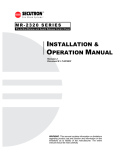
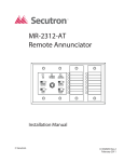
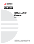
MR-2300 SERIES
LCD Fire Alarm Control Panel
USER
GUIDE
Revision A
Document #: LT-954SEC
WARNING: This manual contains information on limitations
regarding product use and function and information on the
limitations as to liability of the manufacturer. The entire
manual should be read carefully.
MR-2300 Series LCD Version User Guide
Contents
Introduction .............................................................................................................................. 1
About this Manual ................................................................................................................. 1
Technical Support ................................................................................................................. 1
Main Display ............................................................................................................................. 1
The Buzzer and LED Indicators .............................................................................................. 2
Buzzer................................................................................................................................... 2
AC On LED ........................................................................................................................... 2
Alarm LED............................................................................................................................. 2
Supervisory LED ................................................................................................................... 2
Trouble LED.......................................................................................................................... 2
CPU Fail LED........................................................................................................................ 2
Main Display Buttons............................................................................................................... 3
System Reset Button ............................................................................................................ 3
Signal Silence Button............................................................................................................ 3
Fire Drill Button ..................................................................................................................... 3
Lamp Test Button.................................................................................................................. 3
Buzzer Silence Button........................................................................................................... 3
The Up and Down Arrow Buttons ......................................................................................... 3
The Info Button ..................................................................................................................... 3
The Enter, Menu, and Cancel Buttons.................................................................................. 3
Disconnecting/Reconnecting a Circuit (Zone) ...................................................................... 4
Understanding On-screen Messages..................................................................................... 5
Common Messages .............................................................................................................. 6
Glossary.................................................................................................................................... 10
i
MR-2300 Series LCD Version User Guide
Introduction
About this Manual
This user’s guide provides information on the main indicators and controls of the MR-2300 Fire Alarm Control
Panel. Specifically, with this manual you will learn about:
• What the LEDs on the main display indicate
• What the buttons on the main display do
• What certain common LCD screen messages mean
Refer to the Glossary on page 11 for an explanation of commonly used terms in this manual.
Technical Support
For all technical support inquiries, please contact Mircom’s Technical Support Department between 8 A.M. and 5
P.M. (EDT) Monday through Friday, excluding holidays.
Toll-Free Phone: 1-888-SECUTRON (1-888-732-8876)
Local Fax: 905-660-4113
Toll-Free Fax: 1-888-660-4113
Main Display
Refer to the diagram below for the LCD display, LED indicators, and control buttons locations.
System Normal
18:01 MON 2003-04-05
SYSTEM
RESET
A.C. ON
SIGNAL
SILENCE
1
FIRE
DRILL
4
BUZZER
SILENCE
7
LAMP
TEST
*
ALARM
SUPV
2
TRBL
3
ABC
5
GHI
PRS
0
ENTER
DEF
6
JKL
8
TUV
QZ
CPU FAIL
MENU
MNO
9
#
WXY
CANCEL
INFO
The main display panel on the fire alarm control board consists of:
• Five LED indicators (located just below the LCD screen)
• Five buttons (left edge of display)
• 16 program buttons (right part of display)
LED indicators may be amber, red, or green, and may illuminate continuously (steady), or at one of two flash rates:
• Fast flash (supervisory): 120 flashes per minute
• Trouble flash (trouble): 20 flashes per minutes
1
The Buzzer and LED Indicators
The Buzzer and LED Indicators
A.C. ON
ALARM
SUPV
TRBL
CPU FAIL
Buzzer
The buzzer sounds if there is a fire alarm, a supervisory alarm, or a trouble in the fire alarm system. It turns off if the
condition causing the buzzer to sound goes away or the Buzzer Silence button is pressed.
AC On LED
The green AC On LED illuminates steadily as long as the main power is above minimum level. The indicator turns
off when the level falls below the minimum level and the panel switches to standby (battery) power.
Alarm LED
The red Alarm LED will illuminate steadily whenever there is a fire alarm. This indicator will remain on until the
system is reset.
Supervisory LED
The amber Supervisory LED illuminates at the fast flash rate when there is a supervisory alarm in the fire alarm
system. For non-latching supervisory alarms, the Supervisory LED will turn off when the condition causing the alarm
goes away. For latching supervisory alarms, this LED remains on until the panel is reset.
Trouble LED
The Trouble LED flashes amber at the trouble flash rate when the panel detects any trouble condition. For nonlatching trouble conditions, the Supervisory LED will turns off when the condition causing the alarm goes away. For
latching trouble conditions, this LED remains on until the panel is reset.
CPU Fail LED
The CPU Fail LED flashes amber at the trouble flash rate to indicate a microprocessor failure on the main board.
2
MR-2300 Series LCD Version User Guide
Main Display Buttons
System Reset Button
The System Reset button resets the fire alarm control panel and all circuits.
SYSTEM
RESET
Signal Silence Button
SIGNAL
SILENCE
Pressing the Signal Silence button when the panel is in alarm deactivates any silenceable signal
devices in the fire alarm system. Non-silenceable signal devices are unaffected. If you press the
Signal Silence button a second time, or if there is a subsequent alarm, the signals will re-sound. If
the panel has been configured with a Signal Silence Inhibit timer, this button will not work until the
timer times out. This button also does not work if you have pressed the Fire Drill button.
Fire Drill Button
FIRE
DRILL
Pressing the Fire Drill button will simulate a fire alarm by activating the fire alarm signals without
transmitting an alarm to the central station. To cancel the fire drill, press the button again. If the fire
alarm system goes into a real alarm while you are performing a fire drill, this button will not turn off
the signals or operate any programmed relays.
Lamp Test Button
LAMP
TEST
Pressing and holding the Lamp Test button causes the LCD to display the software version, all the
front panel LEDs to illuminate, and sounds the buzzer. Use this button to test that the LCD display
and all LEDs on the main display are working. If you hold the Lamp Test button for more than ten
seconds, the Trouble LED will illuminate.
Buzzer Silence Button
BUZZER
SILENCE
Pressing the Buzzer Silence button while the buzzer is sounding silences the
buzzer. The buzzer will resound if there is a subsequent event. Pressing the
button when the buzzer is not sounding has no effect.
The Up and Down Arrow Buttons
2
ABC
Use these buttons to scroll through any events listed on the screen. The up arrow moves to the
next listed condition and the down arrow moves to the previously listed condition.
8
TUV
The Info Button
INFO
Press the Info button while the there is a message on the LCD screen to view additional
information.
The Enter, Menu, and Cancel Buttons
The Enter, Menu, and Cancel buttons are only used by technicians to program the fire alarm control panel.
3
Disconnecting/Reconnecting a Circuit (Zone)
Disconnecting/Reconnecting a Circuit (Zone)
You can disconnect and reconnect detection and signal circuits (zones) from the panel using the bypass options in
the menu.
To select the bypass options, you must be in the Command Menu. To enter the Command Menu, press
MENU
.
Step 1: Enter your passcode
1.
Enter the
passcode
Enter your passcode.
2. Press
ENTER
to continue.
Step 2: Select the Bypass Menu
- Bypass Det
Zone -
1. Use
and
2
8
TUV
ABC
È
to scroll the cursor to select
the zone you would like to disconnect / reconnect.
2. Press
ENTER
to continue.
Step 3: Select “BYPASSED” or “UNBYPASSED”
1. Use
and
2
8
TUV
ABC
to scroll the cursor to
• “Bypassed” to disconnect a circuit
or
• “Unbypassed” to reconnect a circuit
Zone-1
[ ] BYPASSED
È
2. Use
4
GHI
and
to toggle the selection ON
6
MNO
(“X” appears), or OFF (space is blank).
3. Press
ENTER
4. Press
CANCEL
to continue.
twice to return to the main menu.
If you have disconnected (bypassed) a circuit, a trouble message will display on the main screen until the circuit is
reconnected.
4
MR-2300 Series LCD Version User Guide
Understanding On-screen Messages
The LCD screen of the fire alarm control panel displays messages regarding system events. System events display
on the screen in a queue. Events in this queue are listed on the screen in order of priority: alarms are of highest
priority, followed by supervisory, trouble, and monitor conditions. If the same type of event happens more than once
(for example, two trouble conditions occur successively) they will be listed in the order of the most recent event to
the least recent event. If an alarm, supervisory, or trouble condition occurs, their respective LED will flash.
Scroll through the events by using the
displayed event, press
INFO
2
ABC
and
8
TUV
arrow buttons. If you need more information about a
.
Example 1 (detection circuit)
The message below indicates that event 1 of 9 is an open trouble at the East Lobby Entrance. When
INFO
is
pressed, the screen shows that the process type is a verified alarm on Z-01 and the event occurred on Tuesday
April 4, 2003 at 18:01.
ZO N E
M essag e
P ro c ess
T yp e
EAST LOBBY ENTRANCE
OPEN TRB
01/09
EVENT
typ e
EVEN T
01 of 09
"I N F O " K e y
P h ysic al
Zone N o.
VERIFIED ALARM
Z-01
18:01 TUE 2003-04-04
T IM E
DATE
Example 2 (indicating circuit):
The message below indicates that event 2 of 9 is a short trouble at the East Wing Lobby. When
INFO
is pressed,
the screen shows that the process type is silenceable on NAC-1 and the event occurred on Tuesday February 2,
2003 at 18:01.
ZZONE
ONE
Message
M
essag e
Process
P ro c ess
TType
yp e
EAST WING LOBBY
SHORT TRB
EVENT
EVENT
Message
typ e
"I N F O " KKey
ey
“INFO”
02/09
EVENT
EVEN T
02
0
2 of
o f 09
09
SILENCE-ABLE
PPhysical
h ysic al
ZZone
o n e NNo.
o.
NAC-1
18:01 TUE 2003-02-02
TIME
T IM E
DATE
DATE
5
Understanding On-screen Messages
Common Messages
Common system messages are outlined below.
AC Power Fail
The “AC Power Fail” message indicates that the power has dropped below the minimum level and the system is
running on backup battery power. The trouble is removed when the power returns to the normal value.
T ro u b le c o d e
T ro u b le T yp e
AC Power Fail
Active
"IN F O " K e y
1/ 1
T ro u b le In fo
Trb:0x03 Info:0x0004
00:07 SAT 2000-01-01
T IM E
EVENT
01 of 01
DATE
Battery Trouble
The “Battery Trouble” message indicates that the battery voltage has dropped below the minimum value. The
trouble is restored when the voltage returns to the normal value.
T ro u b le c o d e
T ro u b le T yp e
Battery Trouble
Active
"IN F O " K e y
1/ 1
EVENT
01 of 01
T ro u b le In fo
Trb:0x03 Info:0x0008
00:07 SAT 2000-01-01
T IM E
DATE
Note: The trouble code is a reference code for trained service personnel only.
6
MR-2300 Series LCD Version User Guide
Ground Fault
The “Ground Fault” message indicates that
T ro u b le co d e
T ro u b le T yp e
Ground Fault
Active
"I N F O " K e y
1/ 1
T ro u b le In fo
Trb:0x03 Info:0x0001
00:07 SAT 2000-01-01
T IM E
EVEN T
01 of 01
DATE
RAU num mismatch
The “RAU num mismatch” message can display for one of two reasons: either the main panel and annunciator
failed to communicate with each other or an unconfigured remote annunciator is communicating with the main
panel. In both the cases, the following trouble message is displayed:
T ro u b le T yp e
T ro u b le c o d e
RAU num mismatch
trouble
"I N F O " K e y
1/ 1
EVEN T
01 of 09
T ro u b le in fo
Trb:0x03 Info:0x0001
11:45 SAT 2003-02-03
T IM E
DATE
Note: The trouble code is a reference code for trained service personnel only.
7
Understanding On-screen Messages
4Wire Pwr. Supply
The “4Wire Pwr. Supply” message indicates that the panel has detected a short on a four-wire smoke supply the
power is cut off and a trouble message is generated. Press the
SYSTEM
RESET
key to restore the power the system. If the
short is removed, the panel will return to normal; otherwise the trouble message will stay.
T ro u b le c o d e
T ro u b le T yp e
4Wire Pwr. Supply
short
"IN F O " K e y
1/ 1
T ro u b le In fo
Trb:0x03 Info:0x0001
00:07 SAT 2000-01-01
T IM E
EVENT
01 of 01
DATE
Supervised Aux-supply
The “Aux. Power Supply” message indicates that the panel has detected a short on the auxiliary power supply
(battery backup) and has cut it off. Press
SYSTEM
RESET
to restore the power the system. If the short is removed, the panel
will return to normal; otherwise the trouble message will stay.
T ro u b le c o d e
T ro u b le T yp e
Aux. Power Supply
short
1/ 1
EVENT
01 of 01
"IN F O " K e y
T ro u b le In fo
Trb:0x03 Info:0x0001
00:07 SAT 2000-01-01
T IM E
DATE
Note: The trouble code is a reference code for trained service personnel only.
8
MR-2300 Series LCD Version User Guide
City tie Polarity reversal - SPR-200/ Relay module
The “CtyTie/MR2312 missin” message below indicates that the city tie, polarity reversal module or the relay module
is not plugged in.
T ro u b le co d e
T ro u b le T yp e
Cty T i e/M
R MR3213 21 2 m m
i si sssii nn g
Active
"I N F O " K e y
1/ 1
T ro u b le In fo
Trb:0x03 Info:0x0001
00:07 SAT 2000-01-01
T IM E
EVEN T
01 of 01
DATE
The “City Tie trouble” message below indicates that the panel detects an open on the city tie output.
T ro u b le co d e
T ro u b le T yp e
City Tie trouble
Active
"I N F O " K e y
1/ 1
EVEN T
01 of 01
T ro u b le In fo
Trb:0x03 Info:0x0001
00:07 SAT 2000-01-01
T IM E
DATE
Note: The trouble code is a reference code for trained service personnel only.
9
Glossary
Glossary
Alarm Condition
Occurs when devices such as detectors, pull stations, or sprinklers are activated. In a single stage system, this
condition will activate all signalling devices throughout the building. In a two stage system, this condition will activate
an alert signal and the General Alarm timer.
Circuits
Refers to an actual electrical interface and can be classified as initiating (detection), indicating (signal), or relay. The
terms “circuit” and “zone” are often used interchangeably in the fire alarm industry.
Fast Flash Rate
120 flashes per minute is the rate at which an LED will flash to indicate a supervisory alarm.
Indicating Circuit
A circuit in a fire alarm system that is connected to audible or visual signalling devices.
Initiating Circuit
A circuit in a fire alarm system that is connected to detectors, pull stations, or sprinter flow switches.
Latching Circuit
A circuit that, when activated, will cause a condition on the panel that cannot be cleared until the panel is reset.
LED
The light-emitting diodes (LEDs) of the MR-2300 are colored either amber, red, or green. When lit, LEDs provide
information regarding the status of the panel.
Monitor Condition
Occurs when dampers open or close, when supply and return fans are running, etc.
Non-latching Circuit
A circuit that, when activated, will cause a condition on the panel that will be cleared once the circuit is deactivated.
This term is used to describe supervisory and trouble circuits.
Non-Silenceable Circuit
A signal circuit that cannot be silenced by pressing the Signal Silence button.
Relay Circuit
A circuit in a fire alarm system that connects relay devices (e.g. fan damper relays, etc).
Remote Annunciator
A device that visually indicates, either by LCD or LEDs, the floor or zone where the alarm originated.
Silenceable Circuit
A signal circuit that can be silenced by pressing the Signal Silence button.
Supervisory Condition
Occurs when the system detects open circuits, short critics, and grounds. A supervisory condition is one that would
interfere with the operation of
the fire alarm system.
Trouble Condition
Occurs when an abnormal condition such as a problem in the wiring, battery or power circuits exists in the fire alarm
system.
10
MR-2300 Series LCD Version User Guide
Trouble Flash Rate
20 flashes per minute is the rate at which an LED will flash to indicate a trouble condition.
Walk Test
A test performed by a technician to ensure that each detection device is connected to the panel and working
properly.
Zones
A fire alarm protected area that consists of at least one circuit. The terms “circuit” and “zone” are often used
interchangeably in the fire alarm industry.
11
© 2006 Secutron, Inc.
No part of this publication may be reproduced, transmitted,
transcribed, stored in a retrieval system, or translated into
any language or computer language, in any form by any
means electronic, magnetic, optical, chemical, manual, or
otherwise without the prior consent of Secutron.
Canada
25 Interchange Way
Vaughan, ON L4K 5W3
Tel:
(888) SECUTRON
(888) 732-8876
Fax:
(905) 660-4113
U.S.A
60 Industrial Parkway, PMB 278
Cheektowaga, New York 14227
Tel:
(888) SECUTRON
(888) 732-8876
Fax:
(905) 660-4113