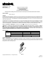
1
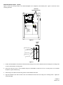
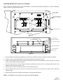
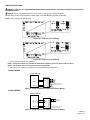
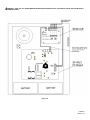
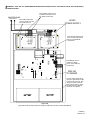
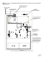
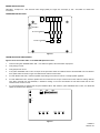
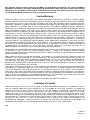
273 Branchport Avenue
Long Branch, N.J. 07740
(800) 631-2148
www.wheelockinc.com
Thank you for using our products.
INSTALLATION INSTRUCTIONS
CLASS A/B SPLITTER
(FOR SP40/2 AND SPB-160/SPB-80/4)
Use this product according to this instruction manual. Please keep this instruction manual for future reference.
MODEL NUMBER:
109900 SP4Z-A/B
GENERAL:
The Class A/B Splitter (SP4Z-A/B) is designed to be used with Wheelock’s SP40/2 SAFEPATH4 panel and the SAFEPATH4 Audio
Booster (SPB-160 and SPB-80/4) panels. The SP4Z-A/B provides a means for expanding one supervised audio output zone to four
Class B or two Class A zones. The SP4Z-A/B is UL Listed under Standard 864, Control Units for Fire Protective Signaling Systems.
They are for indoor use only.
One SP4Z-A/B can be connected to the SP40/2 panel. It is to be mounted inside the panel enclosure onto the backplane in the upper
right hand corner. Two SP4Z-A/B's can be connected to the SPB-160. One SP4Z-A/B can be connected to the SPB-80/4. It is to be
mounted inside the SPB-160 or SPB-80/4 panel on the Splitter Mounting Bracket (SPMB-4Z - purchased separately) mounted over the
24VDC Power Supply (SAPS). The SP4Z-A/B has a maximum power output per zone that cannot exceed what is listed in Table 1.
NOTE: All CAUTIONS and WARNINGS are identified by the symbol
. All warnings are printed in bold capital letters.
WARNING: PLEASE READ THESE INSTRUCTIONS CAREFULLY BEFORE USING THIS PRODUCT. FAILURE TO COMPLY
WITH ANY OF THE FOLLOWING INSTRUCTIONS, CAUTIONS AND WARNINGS COULD RESULT IN IMPROPER APPLICATION,
INSTALLATION AND/OR OPERATION OF THESE PRODUCTS IN AN EMERGENCY SITUATION, WHICH COULD RESULT IN
PROPERTY DAMAGE AND SERIOUS INJURY OR DEATH TO YOU AND/OR OTHERS.
SPECIFICATIONS:
Table 1.
Class A
Class B
Operating Voltage
Maximum Output Power Per Zone
Audio Output Voltage
Standby/Alarm Current at 24VDC
Maximum Output Power Per Zone
25.0V
40.0W
70.7V
40.0W
24VDC
15mA
20W
20W
WIRING INSTRUCTIONS:
NOTE: The terminal blocks on the SP4Z-A/B are removable. To remove a terminal block, pull the block straight up from the
circuit board as shown in Figure 1. Attach wires to the desired connections, then plug the terminal block back on the board
being careful to match and align the pins.
Figure 1.
Copyright 2003 Wheelock, Inc. All rights reserved.
P84205 K
Sheet 1 of 9
MOUNTING INSTRUCTIONS: (SP40/2)
Figure 2 shows the mounting location of the SP4Z-A/B Splitter to the backplane of the SP40/2 panel. Figure 3 shows the correct
mounting procedure.
SP4Z-A/B
MOUNTING STUDS
N
L
AC
+
STATUS
AC
TROUBLE ALARM
INDICATIONS
When the GREEN "AC" light is ON, the system is energized.
When the YELLOW "TROUBLE" light is ON, there is a fault in the system
which MUST BE CORRECTED.
When the RED "STROBE" light is ON,, the strobe circuit is active.
WARNING
IF THE YELLOW "TROUBLE" LIGHT IS ON, THIS UNIT MAY NOT BE ABLE TO PROVIDE EMERGENCY
MESSAGE ANNOUNCEMENT CAPABILITIES AND COULD RESULT IN PROPERTY DAMAGE, SERIOUS INJURY,
OR DEATH TO YOU AND/OR OTHERS. IN THE EVENT THE "TROUBLE" LIGHT IS ON, YOU SHOULD
CONTACT YOUR SERVICE REPRESENTATIVE IMMEDIATELY.
AUDIBLE
TROUBLE
SILENCE
MICROPHONE OPERATION
1. Hold the microphone within two inches of the mouth and press the
push-to-talk switch on the microphone.
2. Deliver the message. Activation of the microphone will deliver the message
to all circuits.
FOR ADDITIONAL INFORMATION
REFER TO THE OPERATION AND INSTALLATION MANUAL.
BEFORE REMOVING THIS PANEL.
CAUTION
DO NOT ATTEMPT TO REMOVE OR REPLACE
MODULAR PC BOARDS INSIDE WITHOUT
DISCONNECTING ALL POWER SOURCES TO
THIS UNIT FIRST. FAILURE TO DO SO MAY
RESULT IN DAMAGE TO THE PC BOARDS.
DISCONNECTING - FIRST DISCONNECT
BATTERY POWER AT BATTERY TERMINALS
THEN DISCONNECT AC POWER AT THE
POWER SOURCE.
RECONNECTING - FIRST RECONNECT AC
POWER AT THE POWER SOURCE. THEN
RECONNECT BATTERY POWER AT THE BATTERY
TERMINALS.
Figure 2.
RIGHT
SIDE
TOP
MOUNTING SCREW (4)
SP4Z-A/B COVER
COVER STANDOFFS (4)
SP4Z-A/B PC BOARD
MOUNTING STUDS
SP40/2 BACKPLANE
Figure 3.
1.
Position the SP4Z-A/B PC board with the terminal blocks pointing to the top of the SP40/2 enclosure and align the mounting holes
on the PC board with the mounting studs.
2.
Screw the male end of the 4 cover standoffs through the SP4Z-A/B PC board and to the 4 mounting studs on the SP40/2
backplane. Tighten standoffs snug.
3.
Attach wiring in accordance with the wiring section of this installation instruction.
4.
Align the SP4Z-A/B cover with the holes in the cover standoffs and mount the cover using the 4 mounting screws. Tighten the
screws hand tight.
P84205 K
Sheet 2 of 9
MOUNTING INSTRUCTIONS: (SPB-160 and SPB-80/4)
Figure 4 shows the mounting location of the SP4Z-A/B Splitter to the Splitter Mounting Bracket (SPMB-4Z - purchased separately).
Figure 5 shows the correct mounting procedure.
L
N
PS-
PS+
24VDC POWER
SUPPLY (SAPS)
TB1
ZONE
1
ZONE
2
ZONE
3
ZONE
4
CLASS B WIRING
+
+
+
-
-
TROUBLE
AUD
IN
+
-
POWER
TROUBLE
+
+
+
+
+
-
+
-
+
-
24VDC
Z4
POWER
CLASS B WIRING
-
Z3
-
Z2
-
Z1
-
AUD
IN
-
24VDC
-
+
SPLITTER MOUNTING
BRACKET (SPMB-4Z)
Z1
Z2
Z3
Z4
ZONE
1
ZONE
2
ZONE
3
ZONE
4
ZO N E
ZO N E
CLASS A WIRING
ZONE
1
ZONE
2
CLASS A WIRING
ZONE
1
ZONE
2
SPLITTER (SP4Z-A/B)
Figure 4.
SPLITTER COVER
SPLITTER BOARD
(4) #6-32 SCREW
(4) HEX M/F SPACER
(4) LOCKING F SPACER
SPLITTER MTG BRKT
(4) #8-32 KEPS NUT
BACKPLATE
Figure 5.
1.
Mount the Splitter Mounting Bracket (SPMB-4Z) to the SPB-160 or SPB-80/4 according to installation instructions (P84252).
2.
Install the 4 nylon Locking Female Spacers to the mounting bracket by pushing them into place.
3.
Position the SP4Z-A/B PC board with the terminal blocks pointing to the top of the Audio Booster enclosure and align the mounting
holes on the PC board with the mounting studs.
4.
Screw the male end of the 4 Hex M/F Spacers through the SP4Z-A/B PC board and to the 4 Locking Female Spacers on the
5.
Attach wiring in accordance with the wiring section of this installation instruction.
6.
Align the SP4Z-A/B Cover with the holes in the cover spacers and mount the cover using the 4 mounting screws. Tighten the
SPMB-4Z. Tighten standoffs snug plus ¼ turn.
screws hand tight.
7.
Repeat Steps 2 through 6 when installing second splitter in the SPB-160 Audio Booster.
NOTE: One SPMB-4Z mounting bracket can support two SP4Z-A/B splitters.
P84205 K
Sheet 3 of 9
WIRING INSTRUCTIONS:
WARNING: SHUT OFF ALL POWER BEFORE STARTING THE INSTALLATION. ELECTRICAL SHOCK CAN CAUSE DEATH
OR SERIOUS INJURY.
CAUTION: Do not move jumpers while the unit is powered on. Doing so may damage the Splitter.
Jumper Plugs J1 and J3 must be set for either Class A or Class B Wiring (Figures 6A and 6B).
NOTE: Factory setting is for Class B Wiring.
Figure 6A: Setup for Class A Wiring
Figure 6B: Setup for Class B Wiring
1. See Figures 6C and 6D for wiring diagram.
NOTE: Unused zones must have a Listed 10K Ohm EOLR installed to prevent an open trouble condition.
NOTE: Cannot utilize Class A and Class B wiring on single splitter.
2. See Figure 8 or the Splitter cover silkscreen for terminal block wiring designations.
CLASS A WIRING:
SP40/2, SPB-160
OR SPB-80-4
24VDC
AUDIO
+
+
-
SP4Z-A/B
Z1+
+24VDC Z2+
Z3 +
+AUD IN Z4+
-
UL LISTED 10K OHM EOLR
ZONE TERMINATION (IF NOT USED)
Figure 6C: Power Limited For Supervised Class A Wiring.
CLASS B WIRING:
SP40/2, SPB-160
OR SPB-80-4
SP4Z-A/B
UL LISTED
Z1 +
10K OHM EOLR
24VDC
+
+
24VDC
Z2+
Z3 +
TERMINATION (IF NOT USED)
AUDIO +
+AUD IN Z4+ ZONE
- UL LISTED 10K OHM EOLR
Figure 6D: Power Limited For Supervised Class B Wiring.
P84205 K
Sheet 4 of 9
WARNING: SHUT OFF ALL POWER BEFORE STARTING THE INSTALLATION. ELECTRICAL SHOCK CAN CAUSE DEATH
OR SERIOUS INJURY.
Figure 7A:
P84205 K
Sheet 5 of 9
WARNING: SHUT OFF ALL POWER BEFORE STARTING THE INSTALLATION. ELECTRICAL SHOCK CAN CAUSE DEATH
OR SERIOUS INJURY.
Place Splitter output wire run
at least 1/4" above the top of
the splitter circuit board.
SPLITTER ZONE
OUTPUTS
Z1
Z2
+
Z3
+
+
+
+
+
+
-
+
+
-
-
-
-
+
-
+
AU D
IN
Place 24VDC Splitter power
wire run at least 1/4" above
the top of the SPB-160
circuit board.
Z4
P O W ER
P O W ER
TR O U B LE
TR O U B LE
C LAS S B
-
2 4VD C
Z4
-
Z3
-
Z2
-
Z1
-
AU D
IN
2 4VD C
24VDC
POWER SUPPLY
-
+
Place AUD1 and AUD2
wire run at least 1/4" from
the 24VDC wire run.
ZO NE ZO NE ZO NE ZO NE
1
2
3
4
W IR IN G
ZO NE
1
C LAS S A W IR IN G
C LAS S B
ZO NE
2
ZO NE ZO NE ZO NE ZO NE
1
2
3
4
W IR IN G
ZO NE
1
C LAS S A W IR IN G
ZO NE
2
F2
TB1
L
AC IN
N
TB4
TRANSFORMER
J1B
25
70
DC IN
DC OUT
F1
J3
25
70
BATTERY
D59
AC
AC TRB
D27
LVL
TB2
D26
AUD2 OPEN
BAT TRB
D30
D33
W7
J3
J5
AUD2 SHORT
D29
W2
25
70
25
70
TB5
AUD IN
AUD2 OUT
AUD1
SHORT
AUD RET
J2
AUX IN
25
70
R23
D28
AUX
TRB
D32
STB2 OUT
AUD1 OPEN
D31
TROUBLE
AUX RET
AUD1 OUT
D24
SW1
STB1 OUT
W1
W3
TB6
D22
AMP TRB
SW4
EXP SHORT
D77
EXP OUT
EXP OPEN
NO CON
C T
NO R
NC B
D76
W10
GF
D34
W5
Place Battery wire run
at least 1/4" above
the top of the SPB-160
circuit board.
SPB-160
PC BOARD
W8
W4
W6
EXP OUT
D75
Run the Audio Output wiring
along the right side and to the
bottom of the enclosure, then
along the bottom to the left
side of the enclosure, up the
left side and to the AUD IN
terminals of the splitter.
Figure 7B:
Figure 7B shows the wiring routes for wiring the SPB-160 to the AUD1 and AUD2 Splitters.
P84205 K
Sheet 6 of 9
WARNING: SHUT OFF ALL POWER BEFORE STARTING THE INSTALLATION. ELECTRICAL SHOCK CAN CAUSE DEATH
OR SERIOUS INJURY.
Place Splitter output wire run
at least 1/4" above the top of
the splitter circuit board.
SPLITTER ZONE
OUTPUTS
Z3
+
+
+
-
-
-
+
+
Z2
-
Z1
-
AU D
IN
2 4VD C
24VDC
POWER SUPPLY
-
+
Place AUD1 and AUD2
wire run at least 1/4" from
the 24VDC wire run.
Place 24VDC Splitter power
wire run at least 1/4" above
the top of the SPB-80/4
circuit board.
Z4
P O W ER
TR O U B LE
C LAS S B
ZO NE ZO NE ZO NE ZO NE
1
2
3
4
W IR IN G
ZO NE
1
C LAS S A W IR IN G
ZO NE
2
F2
TB1
L
AC IN
N
TB4
TRANSFORMER
J1B
25
70
DC IN
DC OUT
F1
J3
25
70
BATTERY
D59
AC
AC TRB
D27
LVL
D26
AUD2 OPEN
BAT TRB
D30
D33
W7
TB2
J3
J5
AUD2 SHORT
D29
W2
25
70
25
70
TB5
AUD IN
AUD1 OUT
AUD1
SHORT
AUD RET
J2
AUX IN
25
70
R23
D28
AUX
TRB
D32
STB1 OUT
AUD1 OPEN
D31
TROUBLE
AUX RET
STB2 OUT
Place Battery wire run
at least 1/4" above
the top of the SPB-80 /4
circuit board.
D24
SW1
W1
W3
TB6
D22
EXP SHORT
D77
AMP TRB
EXP OUT
NO CON
C T
NO R
NC B
EXP OPEN
SW4
D76
W10
STB2 OUT
GF
D34
STB1 OUT
W5
SPB-80/4
PC BOARD
W8
W4
W6
EXP OUT
D75
Run the Audio Output wiring
along the right side and to the
bottom of the enclosure, then
along the bottom to the left
side of the enclosure, up the
left side and to the AUD IN
terminals of the splitter.
Figure 7C:
Figure 7C shows the wiring routes for wiring the SPB-80/4 to the AUD1 Splitter.
P84205 K
Sheet 7 of 9
WIRING SPECIFICATIONS:
Cable Size: Accepts #12 - #18 American Wire Gauge (AWG) for single wire connection or #16 - #18 AWG for double wire
connections.
Z2
Z3
+
+
+
+
-
-
-
+
-
Z1
-
AUD
IN
24VDC
-
+
OPERATING INSTRUCTIONS:
Z4
POWER
TROUBLE
ZONE ZONE ZONE ZONE
4
3
1
2
CLASS B WIRING
ZONE
1
CLASS A WIRING
ZONE
2
Figure 8.
TROUBLESHOOTING PROCEDURES:
Figure 9 Power and trouble LED's on the SP4Z-A/B Splitter PC board.
1.
Insure that the green POWER LED is “ON”. If no LED's are lighted, check the 24VDC input power.
2.
Verify wiring is correct.
3.
Verify jumpers are correct.
4.
If the yellow TROUBLE LED is “ON” an output circuit supervision trouble is indicated. Remove the SP4Z-A/B cover and observe
the 8 yellow LED's as shown in Figure 9 to determine the reason for the trouble.
5.
For each SHORT LED “ON”, check the speaker output wiring for that zone for a short or a faulty speaker appliance.
6.
For each OPEN LED “ON”, check the speaker wire run for that zone for an open or that the end of line resistor is missing. With the
zone wiring removed from the SP4Z-A/B, a resistance reading on the zone will indicate the 10K Ohm EOLR and the wire
resistance if the circuit is correct.
7.
If a zone output does not operate and the green POWER LED is “ON" while the yellow TROUBLE LED is “OFF”, the SP4Z-A/B
splitter has malfunctioned. Replace.
PWR
TB1
TB2
TB3
TBL
Z1
OPEN
Z2
OPEN
Z1 SHORT
Z2 SHORT
Z3 SHORT
Z4 SHORT
Z3 OPEN
Z4 OPEN
Figure 9.
P84205 K
Sheet 8 of 9
ANY MATERIAL EXTRAPOLATED FROM THIS DOCUMENT OR FROM WHEELOCK MANUALS OR OTHER DOCUMENTS
DESCRIBING THE PRODUCT FOR USE IN PROMOTIONAL OR ADVERTISING CLAIMS, OR FOR ANY OTHER USE, INCLUDING
DESCRIPTION OF THE PRODUCT'S APPLICATION, OPERATION, INSTALLATION AND TESTING IS USED AT THE SOLE RISK
OF THE USER AND WHEELOCK WILL NOT HAVE ANY LIABILITY FOR SUCH USE.
Limited Warranty
Wheelock products must be used within their published specifications and must be PROPERLY specified, applied,
installed, operated, maintained and operationally tested in accordance with these instructions at the time of installation
and at least twice a year or more often and in accordance with local, state and federal codes, regulations and laws.
Specification, application, installation, operation, maintenance and testing must be performed by qualified personnel for
proper operation in accordance with all of the latest National Fire Protection Association (NFPA), Underwriters'
Laboratories (UL), Underwriters’ Laboratories of Canada (ULC), National Electrical Code (NEC), Occupational Safety and
Health Administration (OSHA), local, state, county, province, district, federal and other applicable building and fire
standards, guidelines, regulations, laws and codes including, but not limited to, all appendices and amendments and the
requirements of the local authority having jurisdiction (AHJ). Wheelock products when properly specified, applied,
installed, operated, maintained and operationally tested as provided above are warranted against mechanical and
electrical defects for a period of three years from date of manufacture (as determined by date code). Correction of
defects by repair or replacement shall be at Wheelock's sole discretion and shall constitute fulfillment of all obligations
under this warranty. THE FOREGOING LIMITED WARRANTY SHALL IMMEDIATELY TERMINATE IN THE EVENT ANY PART
NOT FURNISHED BY WHEELOCK IS INSTALLED IN THE PRODUCT. THE FOREGOING LIMITED WARRANTY SPECIFICALLY
EXCLUDES ANY SOFTWARE REQUIRED FOR THE OPERATION OF OR INCLUDED IN A PRODUCT. WHEELOCK MAKES NO
REPRESENTATION OR WARRANTY OF ANY OTHER KIND, EXPRESS, IMPLIED OR STATUTORY WHETHER AS TO
MERCHANTABILITY, FITNESS FOR A PARTICULAR PURPOSE OR ANY OTHER MATTER.
USERS ARE SOLELY RESPONSIBLE FOR DETERMINING WHETHER A PRODUCT IS SUITABLE FOR THE USER'S PURPOSES,
OR WHETHER IT WILL ACHIEVE THE USER'S INTENDED RESULTS. THERE IS NO WARRANTY AGAINST DAMAGE
RESULTING FROM MISAPPLICATION, IMPROPER SPECIFICATION, ABUSE, ACCIDENT OR OTHER OPERATING CONDITIONS
BEYOND WHEELOCK'S CONTROL.
SOME WHEELOCK PRODUCTS CONTAIN SOFTWARE. WITH RESPECT TO THOSE PRODUCTS, WHEELOCK DOES NOT
WARRANTY THAT THE OPERATION OF THE SOFTWARE WILL BE UNINTERRUPTED OR ERROR-FREE OR THAT THE
SOFTWARE WILL MEET ANY OTHER STANDARD OF PERFORMANCE, OR THAT THE FUNCTIONS OR PERFORMANCE OF
THE SOFTWARE WILL MEET THE USER'S REQUIREMENTS. WHEELOCK SHALL NOT BE LIABLE FOR ANY DELAYS,
BREAKDOWNS, INTERRUPTIONS, LOSS, DESTRUCTION, ALTERATION, OR OTHER PROBLEMS IN THE USE OF A PRODUCT
ARISING OUT OF OR CAUSED BY THE SOFTWARE.
THE LIABILITY OF WHEELOCK ARISING OUT OF THE SUPPLYING OF A PRODUCT, OR ITS USE, WHETHER ON WARRANTIES,
NEGLIGENCE, OR OTHERWISE, SHALL NOT IN ANY CASE EXCEED THE COST OF CORRECTING DEFECTS AS STATED IN
THE LIMITED WARRANTY AND UPON EXPIRATION OF THE WARRANTY PERIOD ALL SUCH LIABILITY SHALL TERMINATE.
WHEELOCK IS NOT LIABLE FOR LABOR COSTS INCURRED IN REMOVAL, REINSTALLATION OR REPAIR OF THE PRODUCT
BY ANYONE OTHER THAN WHEELOCK OR FOR DAMAGE OF ANY TYPE WHATSOEVER, INCLUDING BUT NOT LIMITED TO,
LOSS OF PROFIT OR INCIDENTAL OR CONSEQUENTIAL DAMAGES. THE FOREGOING SHALL CONSTITUTE THE SOLE
REMEDY OF THE PURCHASER AND THE EXCLUSIVE LIABILITY OF WHEELOCK.
IN NO CASE WILL WHEELOCK'S LIABILITY EXCEED THE PURCHASE PRICE PAID FOR A PRODUCT.
Limitation of Liability
WHEELOCK'S LIABILITY ON ANY CLAIM OF ANY KIND, INCLUDING NEGLIGENCE AND BREACH OF WARRANTY, FOR ANY
LOSS OR DAMAGE RESULTING FROM, ARISING OUT OF, OR CONNECTED WITH THIS CONTRACT, OR FROM THE
MANUFACTURE, SALE, DELIVERY, RESALE, REPAIR OR USE OF ANY PRODUCT COVERED BY THIS ORDER SHALL BE
LIMITED TO THE PRICE APPLICABLE TO THE PRODUCT OR PART THEREOF WHICH GIVES RISE TO THE CLAIM.
WHEELOCK'S LIABILITY ON ANY CLAIM OF ANY KIND SHALL CEASE IMMEDIATELY UPON THE INSTALLATION IN THE
PRODUCT OF ANY PART NOT FURNISHED BY WHEELOCK. IN NO EVENT SHALL WHEELOCK BE LIABLE FOR ANY CLAIM OF
ANY KIND UNLESS IT IS PROVEN THAT OUR PRODUCT WAS A DIRECT CAUSE OF SUCH CLAIM. FURTHER, IN NO EVENT,
INCLUDING IN THE CASE OF A CLAIM OF NEGLIGENCE, SHALL WHEELOCK BE LIABLE FOR INCIDENTAL OR
CONSEQUENTIAL DAMAGES. SOME STATES DO NOT ALLOW THE EXCLUSION OR LIMITATION OF INCIDENTAL OR
CONSEQUENTIAL DAMAGES, SO THE PRECEDING LIMITATION MAY NOT APPLY TO ALL PURCHASERS.
3/03
P84205 K
Sheet 9 of 9