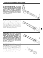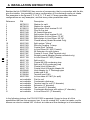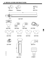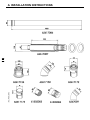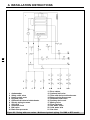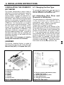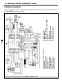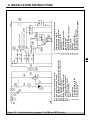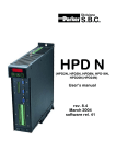
1
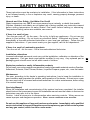
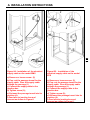
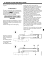
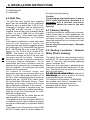
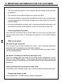
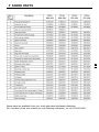
INSTRUCTION MANUAL For installation, use and maintenance for the 5-41-5 MODELS: BMS & BTS Direct Vent Space / Water Heater These instructions MUST be read prior to installation and left near the appliance when the installation is completed. 120601 Text complies with minimum size requirements. U.S.A. Combined Appliance For Heating and Domestic Hot Water 62403262 - R1 SAFETY INSTRUCTIONS WARNING: If the information in this manual is not followed exactly, a fire or explosion may result causing property damage, personal injury or death. Do not store or use gasoline or other flammable vapors and liquids in the vicinity of this or any other appliance. WHAT TO DO IF YOU SMELL GAS 2 Do not try to light any appliance. Do not touch any electrical switch; do not use any phone in your building. Immediately call your gas supplier from a neighbors phone. Follow the gas suppliers instructions. If you cannot reach your gas supplier, call the fire department. Installation and service must be performed by a qualified installer, service agency or the gas supplier. FOR YOUR SAFETY Do not store or use gasoline or other flammable, combustible, or corrosive vapors and liquids in the vicinity of this or any other appliance. SAFETY INSTRUCTIONS These instructions must be read prior to installation. If the information in these instructions is not followed exactly, a fire or explosion may result, causing property damage, personal injury, or death. Hazards and Your Safety - Hot Water Can Scald! Water temperature over 125°F can cause severe burns instantly, or death from scalds. Children, disabled, and elderly are at highest risk of being scalded; see instruction manual before setting temperature at water heater! Feel water before bathing or showering. Temperature limiting valves are available, see manual. If there is a smell of gas: -Turn the gas cock off - Air the room - Do not try to light any appliances - Do not use any phone in your building - Do not touch any electrical switch - Extinguish any flames - Call immediately a licensed authorized technician or your local gas company - Follow the gas suppliers instructions - If you cannot reach your gas supplier, call the fire department. If there is a smell of combustion products: -Turn the unit off - Air the room - Call a licensed authorized technician. Installation, alterations Licensed authorized personnel must carry out the installation, calibration or alteration of the gas apparatus. Flue gas ducts must not be modified in any way. Any replaced part or packaging parts should never be left within reach of children. Explosive products or easily inflammable products Do not keep, use or store explosive materials or easily inflammable materials such as Gasoline, Adhesives, Solvents, Paint Thinner, Butane, Liquefied Propane, paper, etc., near the heater. Maintenance The user, according to the heaters operating instructions, has to keep the installation in good condition and guarantee the reliable, safe operation of the heater. At least once a year the user must call in a licensed authorized technician for routine maintenance, before using it for central heating. Servicing Manual When the installation and commissioning of the system has been completed, the installer should instruct the homeowner to save the installation manual near the heater so that service technicians may refer to it in the future. Caution: Label all wires prior to disconnection when servicing controls. Wiring errors can cause improper and dangerous operation. VERIFY PROPER OPERATION AFTER SERVICING. Do not use this appliance if any part has been under water. Immediately call a qualified service technician to inspect the appliance and to replace any part of the control system and any gas control, which has been under water. 3 GENERAL INFORMATION This instruction manual refers to two types of heaters, the BMS and the BTS. BMS - this appliance is a wall mounted, direct vent space/water heater BTS - this appliance is a self standing floor model, direct vent space/water heater Each type of heater can be of two different input power rating; a 10/20 or 15/29; 10/20 has an input power rating of 87,000 (31.6) Btu/hr (kW) 15/29 has an input power rating of 107,000 (26) Btu/hr (kW) BMS 10/20 or BMS 15/29 or BTS 10/20 or BTS 15/29 4 When referring to this instruction manual, be sure of which type of heater you are working with. This can be verified by referring to the data plate marked Space water heater model . This data plate is located on the bottom side of the BMS, or on the inside of the front door (internal side) of the BTS. Also verify the type of gas for which the heater is set. A label in the front of your heater states NATURAL GAS, for heaters set to natural gas, or LP GAS for heaters set to LP gas. TABLE OF CONTENTS GENERAL INFORMATION .................................................................................................. 4 TABLE OF CONTENTS ....................................................................................................... 4 TABLE OF CONTENTS ....................................................................................................... 5 GENERAL LAYOUT of the main components of model BMS ........................................... 6 GENERAL LAYOUT of the main components of model BTS ............................................ 8 GENERAL LAYOUT of the main components of model BTS ............................................ 9 A INSTALLATION INSTRUCTIONS .................................................................................. 10 1 Operating and adjusting the output to the radiation system ........................................ 10 2 Location ..................................................................................................................... 10 3 Installation .................................................................................................................. 10 3.1 Installation Template ......................................................................................... 10 A INSTALLATION INSTRUCTIONS .................................................................................. 11 Clearances for installation ...................................................................................... 11 3.2 Safety Relief Valve ........................................................................................... 12 3.3.1 Installation of two heaters .............................................................................. 12 3.3.2 Installation of three or more heaters ............................................................. 12 TABLE OF CONTENTS 3.3.3 Radiant heating installation ........................................................................... 12 ................................................................................................................................ 12 3.3.4 Used of glycol ................................................................................................ 12 ................................................................................................................................ 13 3.4 Domestic Hot and Cold water ........................................................................... 13 3.5 Water Hardness ............................................................................................... 13 3.6 Gas Supply ....................................................................................................... 13 3.6 Gas Supply (cont.) ............................................................................................ 14 3.7 Electrical Supply Connection ............................................................................ 14 3.8 Room Thermostat Connection ......................................................................... 14 4 VENTING SYSTEMS ................................................................................................. 16 4.1 Concentric Flue (Coaxial) ................................................................................. 16 ATTENTION !!! .............................................................................................................. 17 4.2 Split Flue ........................................................................................................... 18 4.3 Chimney Venting .............................................................................................. 18 4.5 Venting Locations - Outside Walls (Direct Venting) ......................................... 18 4.6 Kit for air intake/flue discharge ......................................................................... 18 5 REGULATING THE DOMESTIC HOT WATER ........................................................... 31 6 BURNER .................................................................................................................... 31 6.1 Changing the Gas Type .................................................................................... 31 6.2 Adjusting Gas Flow and Pressure to the Burner .............................................. 31 7 WIRING DIAGRAMS ................................................................................................. 38 9.4 Summer-Winter Mode ...................................................................................... 42 9.5 Adjusting Central Heating ................................................................................. 42 9.6 Manual Reset High-Limit Thermostat ............................................................... 42 9.7 Resetting the Ignition Module ........................................................................... 42 9.8 Heating Circulator Pump .................................................................................. 42 9.9 Shut-Down Procedure ...................................................................................... 42 9.10 Maintenance ......................................................................................................... 42 9.11 Draining water from the heater .............................................................................. 42 10 - BTS model - INSTRUCTIONS FOR USE ............................................................... 43 10.1 Start-Up Instructions ....................................................................................... 43 10.2 Checks Prior to Ignition .................................................................................. 43 10.3 Ignition Procedure .......................................................................................... 43 10.4 Summer-Winter Mode .................................................................................... 44 10.5 Adjusting Central Heating ............................................................................... 44 10.6 Manual Reset High-Limit Thermostat ............................................................. 44 10.7 Resetting the Ignition Module ......................................................................... 44 10.8 Heating Circulator Pump ................................................................................ 44 10.9 Shut-Down Procedure .................................................................................... 44 10.10 Maintenance ....................................................................................................... 44 10.11 Draining water from the heater ............................................................................ 44 E IMPORTANT INFORMATION FOR THE CUSTOMER ................................................... 48 F SPARE PARTS ............................................................................................................... 49 G TECHNICAL FEATURES .............................................................................................. 50 5 GENERAL LAYOUT of the main components of model BMS A = Flue discharge B = Air intake Coaxial discharge 6 Figure 1 - BMS Front view Split discharge GENERAL LAYOUT of the main components of model BMS 1 2 3 4 5 6 7 8 9 10 11 12 13 14 15 16 17 18 19 20 21 22 23 24 25 26 27 28 29 30 31 32 33 34 35 Figure 2 - BMS Side and top views Central heating supply Central heating return Gas inlet Domestic hot water outlet Cold water inlet Flue gas discharge fan Automatic air vent Thermostat bulb pocket Gas valve service switch Instrument panel Temperature-pressure gauge Failure lamp indicator Ignition and detection electrodes Burner Gas manifold Exchanger shell clamps Gas valve High limit thermostat Power and circulator pump switches Domestic hot water priority thermostat Central heating regulation knob Heater temperature control Electrical control board Ignition module Electrical plastic cover Electrical junction box Expansion tank Pressure switch Domestic water heat exchanger Heat exchanger Turbulator Support bracket Central heating regulation valve Circulator pump Transformer 7 GENERAL LAYOUT of the main components of model BTS 8 Figure 3 - BTS Front view GENERAL LAYOUT of the main components of model BTS 9 1 2 3 4 5 6 7 8 9 10 11 12 13 14 15 16 17 18 19 Central heating supply Central heating return Gas inlet Domestic hot water outlet Cold water inlet Flue gas discharge fan Automatic air vent Thermostat bulb pocket -Instrument panel Temperature-pressure gauge Failure lamp indicator Ignition and detection electrodes Burner Gas manifold -Gas valve High limit thermostat Power and circulator pump switches Figure 4 - BTS side view 20 21 22 23 24 25 26 27 28 29 30 31 32 33 34 35 36 A B Domestic hot water priority thermostat Central heating regulation knob Heater temperature control Electrical control board Ignition module -Electrical junction box Expansion tank Pressure switch ----Central heating regulation valve Circulator pump Transformer Low water cut-off Flue discharge Air intake A INSTALLATION INSTRUCTIONS 1 Operating and adjusting the output to the radiation system The COSMOGAS heater can be installed in any domestic or light commercial building where the maximum BTU/H required is not greater than 84,000 BTU/H. The unit has a internal mixing valve (heating side only) that can be adjusted to regulate the supply water temperature delivered to the heating system. The heating system will not receive any water unless the water temperature inside of the heater is at a minimum of 140°F. The heater built-in domestic hot water priority thermostat will cease the power to the circulator until the temperature is greater than 140°F. installed on a metal or wood panel extending behind the full width and depth of the appliance by at least 3, (76.2 mm), in any direction or, if the appliance is installed in an alcove or closet, the entire floor shall be covered by the panel. 3.1 Installation Template ONLY model BMS is provided with an installation 2 Location 10 This space/water heater unit is not intended for outdoor installation. Choose a location centralized to the piping system along with consideration to the vent pipe length. Additionally, you will need to place the space/water heater so that the controls, drain, inlet/outlet, and gas valve are easily accessed. Also, care must be exercised when choosing the location of this appliance, where leakage from the safety relief valves, leakage from related piping, or connections, will not result in damage to the surrounding areas, or to the lower floor of the building. No valve is to be placed between the safety relief valves and the heater. The discharge from the temperature and pressure relief valve must be conducted to a suitable place for disposal. No reducing coupling or other restriction shall be installed in the discharge line. The discharge line should allow complete drainage of both valve and line. Figure 5 3 Installation The installation must conform to local codes and ordinances or, in the absence of local codes, the National Fuel Gas Code ANSI Z 223.1/NFPA 54 1984. When installed the appliance must be electrically grounded in accordance with the National Electrical Code, ANSI/NFPA No.70 1987. For Canada, the installation should conform to CGA B149.1 INSTALLATION CODES and/or local installation codes. The gas supply piping system should be tested before the heater is connected. The heater, (complete with all its parts: external jacket, intake and discharge flue pipes, etc.), must be installed leaving a distance of at least 10 cm, (4), from sidewalls and ceiling. Installation of the BTS combi directly on combustible flooring such as carpeting shall be Figure 5 - Installation template, Only for model BMS A INSTALLATION INSTRUCTIONS template to facilitate proper installation alignments (See figure 5 below). Clearances installation for The figures 5A and 5B show the proper distances to keep from any obstacle pertaining to the support bracket (2) or to the wall. The procedure for installing the BMS is as follow: 1) - Take the support bracket (2) and choose a position with proper clearances, as per Figures 5A & 5B. A minimum clearance of 40 (100mm) is required from the front of the heater. WARNING: Please take caution when choosing a mounting surface for the heater. The weight of the heater with water is approximately 165 lbs. Make certain that the wall can support such weight. Figure 5A - Clearances for model BMS 2) Screw the bracket to the wall. The screws MUST screwed in correspondence of the 16" vertical studs. 3) Place the template onto the support bracket and make all rough-in holes for the piping to the heater. The hole for the coaxial flue vent kit discharge may also be cut at this time. 4) Install the heater on the support bracket and secure all of the connections. Figure 5B - Clearances for model BTS 11 A INSTALLATION INSTRUCTIONS 3.2 Safety Relief Valve An ASME approved safety relief valve, (set at 30 psi), must be installed in a vertical position on the outlet side of the central heating system, and as close as possible to the heater. There must be no valves between the safety relief valve and the heater. Manually operate the safety relief valve at least once a year to ensure proper operation. Precaution must be taken prior to operating the safety relief valve, to avoid contact with hot water coming out of the safety relief valve and to prevent water damege. If the safety relief valve discharges periodically, this may be due to thermal expansion in a closed water supply system. Contact the water supplier or local plumbing inspector on how to correct this situation. Do not plug the safety relief valve. 3.3 Heating Supply and Return 12 The central heating supply and return pipes are marked with different colored caps, (supply red and return blue). If there are any heating elements above heater level, it is advisable to install a check valve on the supply pipe to prevent natural circulation phenomena from occurring. If the heater is to be connected to an existing system it is advisable to wash out and remove any deposits from inside the existing pipes, and install a filter at the lowest point to trap any additional impurities when it is running. This equipment is designed for use in a closed loop system. Installation schematics are found in figures 23 to 28. WARNING !!! All the schematics in figures 23 to 28 are only samplesl. Safety apparatus, pipe diameters, and auxiliary accessories, must be verified by a qualified personnel only and in accordance with the national and/or local codes. 3.3.1 Installation of two heaters Iinstalling two heaters in parallel. Follow the schema in the figure 23 3.3.2 Installation of three or more heaters Installing three or more heaters in parallel. Follow the schema in the figure 24 3.3.3 Radiant heating installation When the heater is used in conjuction with radiant heating, it is imperative that the tubing contains an oxygen diffusion barrier. If you are unsure whether or not the tubing has a barrier, a heat exchanger must be used to protect the heater from oxygen corrosion (See figure 25). This situation will also occur if the heater is used on an open-loop system where new, cold-fill water is introduced into the system. The oxygen will remove itself from solution and react chemically with the ferrous components (i.e. steel), causing them to rust and corrode. THIS TYPE OF FAILURE IS NOT COVERED BY THE WARRANTY! 3.3.4 Used of glycol If glycol is used with the heater, the glycol must be recognized as safe or approved by the United States Food and Drug Administration for food contact as listed in Code of Federal Regulations, title 21, part 182 of the Food Additive Regulations. Any additives introduced into the heating system must be recognized as safe by the United States Food and Drug Administration. If a non-approved additive is used, it can cause serious health problems or possibly death.The pressure of the heating system side of the heater must be fitted with devices (automatic water feed/pressure reducing valve not to exceed 30 psi) arranged to function automatically in order to maintain the pressure of the heating side at a level below that of the potable water leaving the heat exchanger. 3.4 Domestic Hot and Cold water The domestic hot water flow restrictor must be installed on the cold water inlet, (Refer to figure 25, 26, 27 and 28). For servicing purposes, install a shut-off valve upstream from the cold water inlet. The heaters thermostat can be regulated to provide domestic hot water between 100°F and 180°F. Water temperature over 125°F can cause severe burns instantly. Since it is required that the heater water temperature reach above 140°F in order for the heating system side of the unit to operate, it is imperative that a mixing valve be installed external of the heater to further regulate the temperature of the domestic hot water (See figures 23, 25, 26, 27 and 28). Failure to install a domestic side mixing valve will result in severe burns! Piping and components connected to the water heater for space heating shall be suitable for use with potable water, and shall not be connected to any heating system or components previously used with a nonpotable water heating appliance. The domestic hot water circuit needs an ASME approved temperature and pressure P-T relief valve, set at 150 psi and 210°F, installed as close as possible to the heater. There must be no valves between the P-T relief valve and the heater. The P-T relief valve discharge pipe must not be restricted or plugged. 3.5 Water Hardness In hard water areas (above 150 p.p.m), it is recommended that a suitable water treatment device (softener with filters) be installed. Excessive buildup of minerals in the heat exchanger can cause a non-warranty failure. Water hardness can be determined by using the standard test or by checking with your local water authority. Toxic chemicals, such as used for heater treatment, should not be introduced into the potable water used for space heating. 3.6 Gas Supply Before making any gas connections, verify that the heater is being supplied with same gas type as indicated on the rating plate. The rating plate is located on the front of the BMS, and is located on the front door of the BTS. This heater has orifices which will operate at an altitude of up to 2,000 feet. For installations in higher elevations, down-rate the heater by 10%. Install a manual gas cock outside of the heater. Refer to Figures 1 and 3, item 3, for the gas inlet location of the heater. Gas piping to the heater must be sufficient to guarantee a supply of gas to meet maximum requirements. See Table 1 for max. and min. values of gas pressure (Back of manual). All piping must comply with local codes and ordinances or with the National Fuel Gas Code, (ANSI Z223.1 NFPA No. 54), whichever applies. The appliance and its individual shutoff valve must be disconnected from the gas supply piping system during any pressure testing of that system at test pressures in excess of ½ psig, (3.5 kPa). The appliance must be isolated from the gas supply piping system by closing its individual manual shutoff valve during any pressure testing of the gas supply piping system at test pressures equal to or less than ½ psig, (3.5 kPa). 13 A INSTALLATION INSTRUCTIONS 3.6 Gas Supply (cont.) Length of Gas Pipe 10' 20' 30' 40' 50' 75' 100' 150' Additional length to be added for each bend or tee 14 Capacity of Gas Pipe Size in MBTUH 1/2" 132 92 73 63 1.3' 3.7 Room Thermostat Connection This is installed by removing the electrical junction box cover indicated in fig.6, (see fig.1 and 3, item 26), and connecting the two wires of the room thermostat, or zone valve control thermostat, to the low voltage terminals, (figure 6, item B). NOTE: first remove factory installed jumper from terminals. The room thermostat must always be located in a point of the house where the temperature is not subject to sudden changes. A Electrical supply connection B Room thermostat connection Figure 6 - Connecting the room thermostat and electrical supply 3/4" 278 190 152 130 115 93 79 64 1.7' 1" 520 350 285 245 215 175 150 120 1 1/4" 1050 730 590 500 440 360 305 250 2.2' 2.7' 3.8 Electrical Supply Connection The heater must be connected to a 115V 60Hz, single phase electrical supply fused to 15 amps, Grounding is required as well as the installation of a main emergency switch immediately upstream from the heater. An electrical junction box (see figures 1 and 3, item 26) is provided for connections for both the line voltage of 115V 60 Hz (See figure 6 item A) , and the room thermostat at low voltage of 24Vac (See figure 6 item B). The cable wire of the line voltage must be insered into the heater, through the passcable positioned in the side of the idraulic connections (see figure 7 and 8). A INSTALLATION INSTRUCTIONS 15 Figure 6A - Installation of the electrical supply cable on the model BMS a) Remove or loosen screw (2) b) Pop- out the passage tunnel for the supply cable. Pass the supply cable through the passage (1) c) Connect the supply cable to the junction box d) Tighten screw (2); e) Re-insert the passage tunnel into its position (4). f) Feed wire to junction box and connect as shown in Figure 6. Figure 6B - Installation of the electrical supply cable on the model BTS a) Remove or loosen screw (2) b) Pop- out the passage tunnel for the supply cable. Pass the supply cable through the passage (1) c) Connect the supply cable to the junction box d) Tighten screw (2); e) Re-insert the passage tunnel into its position (4). f) Feed wire to junction box and connect as shown in Figure 6. A INSTALLATION INSTRUCTIONS 4 VENTING SYSTEMS 16 This heater can be fitted with either a concentric or split type venting system. Particular attention must be taken when installing the vent pipes that go through the wall to the outside. It must always be possible to carry out routine maintenance operations of the flue. The vent pipe must be installed in such a way that it can be removed, if needed, in the future. Hence, a suitable sheath should be prepared in which to insert the vent pipe. Both venting systems are suitable for venting through a wall 1 to 24 thick. The connection of the vent air intake system to the heater can turn 360°, which means in all directions, making installation extremely easy. To turn it just loosen the securing screws on the base of the vent elbow where it attaches to the heater, turn to desired position, then tighten the screws without forcing them. You must place the terminal in an open area, and follow the following guidelines: Make certain that exhaust gas does not re-circulate back into the intake pipe. Never vent into a walkway or patio area, or an alley, or otherwise public area less than 7ft from the ground level. This is to prevent anyone from walking into the vent; Never vent over or under a window or over a doorway; Never install a heat saver or similar product to capture waste heat from exhaust; Always have vent 1ft above ground level, away from shrubs and bushes. Follow local gas codes in your region or refer to National Fuel Gas Code, or Can B149.1 INSTALLATION CODES. Always have vent at least 3ft from an inside corner of outside walls. Maintain at least 4ft clearance to electric, gas meters and exhaust fans. Always place screens in all openings in intake and exhaust to prevent foreign matter from entering the heater. The vent terminals, (concentric, split type exhaust), must be a minimum of 1ft above the ground level. If split type vent will be venting into a chimney, make certain that no other appliances are vented into it. This power- vented heater must not share a chimney. Vent exhaust terminal should be inserted into, but not beyond, inner wall of chimney. Do not vent into transient pipe. Warranty will be void. CAUTION! - Take all precautionary measures to allow the angle of the flue to run down slightly to the outside, NEVER rising. Anticipate for all horizontal pipes, an inclination of 1/4 per foot toward the discharge. If a vertical pipe follows a horizontal one, place a condensation discharge fitting in the lowest part of the vertical pipe. A condensation discharge pipefitting must also be used for vertical discharge pipe installations directly from the heater with a pipe whose length is more than 10. During normal operating conditions, the heater will have exhaust gases exiting from the flue pipe. The smoke will be heavier on some days than on others. This is due to the outdoor weather conditions (the temperature, humidity, etc.), and is extremely common. 4.1 Concentric Flue (Coaxial) The (Coaxial) concentric vent, (air inlet and flue outlet), system consists of 2 pipes: the outer one for fresh air intake, the inner pipe for flue exhaust discharge. With optional pipe, it is possible to increase the overall length up to 15ft (4.5 m). There are also 90° concentric elbows available, if they are installed, there will be a loss of draught equal to that caused by 3ft, (1 m), of straight pipe. Connections between the various parts must be secured by using self-tapping screws, (see fig.9). The vents stainless steel end terminal must always come completely out of the outer pipe. If for any reason the intake grid is A INSTALLATION INSTRUCTIONS blocked, the heater will not receive enough air for combustion and the burner would fail to ignite. ATTENTION !!! We want to remember that all accessories in the line of the air intake and in the line of flue discharge MUST be secured with screws beetween them, and MUST be sealed from flue or air leakage PRECAUTION TO BE TAKEN WHEN INSTALLING COAXIAL VENTING Proper assembly and installation of venting elbows and tubing must include the use of self-tapping screws to permanently secure in place the internal discharge tube. Self-tapping screws are used to insure that the discharge vent tube remains in place and not allow discharge gases to re-enter the heater. Failure to secure the internal discharge tube may result in the heater backfiring and causing permanent damage to the heat exchanger. Heaters which have been damaged for this reason are not covered in our limited warranty. The stainless steel (End terminal) wind guard must fit properly and inter-lock into slip joint of intake pipe. It is imperative that the internal discharge pipe first be secured in place with selftapping scews before attaching and securing the external vent pipe. Also, ensure that the two grids of the end terminal come completely out of the outer pipe. If the intake grid is hidden the heater will not receive enough air for combustion and would fail to ignite. Picture # X: First, insert the vent inner pipe into the vent elbow and tighten using selftapping screws Picture # Y: Second, fit the outer pipe and secure it with proper screws See drawings below. K = Screws provided L = Inner pipe M = Screws provided 17 A INSTALLATION INSTRUCTIONS N = This position shall be respected O = Discharge grid P = Intake grid 4.2 Split Flue 18 The split flue vent system (two separate pipes) can be extended (on the discharge side only) up to a total length of 20 ft (6 m). Changes in direction can be obtained by using 90° and 45° elbows. If they are installed, there will be a loss of draught equal to 3ft (1 m) and 1 1/2ft (0.5 m) of straight pipe, respectively. This is valid only for pipes and elbows manufactured by Cosmogas s.r.l.. If the heater is installed in a large open area such as a full basement or alcove, the combustion air could also be supplied without the intake pipe, (For model BMS see figures 8, 11, 12, 13 and 14 or for model BTS see figures 16, 18, 19 and 20 for model BTS). NOTE: The heater will draw all air for combustion through the top of the unit from the space around the heater. Ventilation should be adequate to provide sufficient air to properly support combustion. Air for combustion and room ventilation must be obtained from spaces freely communicating with the outdoors. Air openings to the room should not be obstructed. For heaters in confined rooms, two permanent openings must be provided - one within 12 of the ceiling and one within 12 of the floor. Each opening must be at least one square inch per 1,000 BTU/H heater input, but not less than 100 square inches. These openings must freely connect with areas having adequate infiltration to the outside. When all air provided is supplied from the outdoors, the openings, as described above, shall be of the size listed below for each particular arrangement: - All ducting shall be the same size as the opening which it is to be connected. - One square inch of free area per 4,000 BTU/ H of heater input for direct outdoor air supply through an outside wall or vertical duct directly outside. - One square inch of free area for every 2,000 BTU/H of heater input for direct outdoor air through horizontal ducting. Caution! The discharge pipe temperature is above 250°F while functioning, therefore it is essential that a thermal insulation protection sheath be used in the wall opening. 4.3 Chimney Venting If split type vent will be venting into a chimney, make certain that no other appliances are vented into it. This power-vented heater must not share a chimney. Vent exhaust terminal should be inserted into, but not beyond, inner wall of chimney. Do not vent into transient pipe. Warranty will be void. 4.5 Venting Locations - Outside Walls (Direct Venting) The center line of the vent opening must be at least 16 1/2 above grade, outside, and at least 12 from any other building openings (doors, windows, etc.). Make sure that vent pipe is pitcheed down from the unit toward the outside wall 1/4 per foot. This will prevent any water from running back into the heater. 4.6 Kitlocate for air Do not theintake/flue vent terminal where flue products could strike against building discharge materials and cause corrosion. For comfort for the installer, COSMOGAS has created some flue kit, complete of all the necessary components for flue discharge and air intake. The four kits available are as follows: A INSTALLATION INSTRUCTIONS P/N 62617168. Split vent kit. This kit is for take the air from the room where the heater is installed, and discharge the flue outside from the building. The pipe of discharge is length 2.5ft.. If you need extensiones or elbows or other accessories, refer to figures R, S and T. This kit can be used for heaters model BMS and BTS. P/N 62617174. Coaxial Vent & Elbow Kit. This kit is for taking and discharging air from/ to the outside of the building. The pipe of discharge length is 3ft. If you need extensions, elbows or other accessories, refer to figures O, P and Q. This kit can be used for heaters model BM and BTS. To discharge the flue in vertical position you must to use a roof vent terminal 62617070, (see figure P) 19 P/N 62617175. Coaxial Vent & Straight Adapter Kit. This kit is for taking and discharging air from/to the outside of the building. The pipe of discharge length is 3ft. If you need extensions, elbows or other accessories, refer to figures O, P and Q. This kit can be used for heaters model BM and BTS. To discharge the flue in vertical position you must to use a roof vent terminal 62617070, (see figure P) P/N 62630046. Vent Adaptor for 3" Discharge pipe. This kit is for to connect only the flue discharge to a commercial 3 pipe. This kit must be used toghether with a heater mounted adapter P/N 62617124 or 62617060. With this configuration, the installer is responsible for the materials used and for the installation. In any case follow the national or local codes.. A INSTALLATION INSTRUCTIONS Besides the kits COSMOGAS has a series of accessories, that in conjonction with the kits, give the installer the possibility of many configuration of flue discharge and/or air intake. See exemples to the figures O, P, Q, R, S, T, U and V. Please remember that these configurations are only examples, and that many other possibilities exist. 20 Reference 1 2 3 4 5 6 7 8 9 10 11 12 13 14 15 16 17 18 19 20 21 22 23 24 25 26 A B C D E F G P/N 60702011 60702012 61302011 62617010 62617049 62617053 62617056 62617058 62617060 62617062 62617063 62617070 62617077 62617086 62617087 62617124 62617159 62617168 62617172 62617173 62617174 62617175 62630046 61302003 61302004 62617059 not available not available not available not available not available not available not available Description Washer for split Washer for coaxial Split system Roof terminal D. 80 Plug for flue test 3ft coaxial Extension Split system Roof terminal D. 80 Split system In-Line Elbow FF 90° Split system In-Line Elbow MF 90° Coaxial elbow (Heater Mounted Only) Split system Viking Silicone Coupling + clamp Coaxial Roof Terminal In-Line Elbow 90° M/F (Coaxial) 3ft Extension for split system Coaxial 3 ft vent, (End-Terminal only) Straight coaxial Adapter (Heater mounted only) In-Line Elbow 45° M/F (Coaxial) Split vent kit Coaxial 60/100 condensing trap Split-vent D.80 condensing trap Coaxial Vent & Elbow Kit Coaxial Vent & Straight Adapter Kit Vent Adaptor for 3" Discharge pipe Intake grid D.80 Terminal vent D.80 In-Line elbow 45° M/F (for split) Flat for roof Condensate discharge Terminal vent for roof (3 diameter) Extension (3 diameter) Tee raccord (3 diameter) Condensate discharge with siphon (3 diameter) In-Line Elbow 90° (3 diameter) In the following pictures, the P/N 62617062 is repeated 4 times to show all of the possibilities that has this accessory has. It can be rotated 360° under the heater, and its elbows can also be rotated 360° to direct air intake and flue discharge in all orientations. A INSTALLATION INSTRUCTIONS 21 A INSTALLATION INSTRUCTIONS 22 A INSTALLATION INSTRUCTIONS Figure L Some exemples of vent make with the kits predisposed by COSMOGAS P/N 62617168, P/N 62617174 e P/N 62617175. 62617168 Figure M 62617174 Figure N 62617175 23 A INSTALLATION INSTRUCTIONS 24 Figure O Figure P Some exemples of vent make with some accessories (Figure O and P) or with the combination of a kit P/N 62617174 and some accessories #13 and #5 (Figure Q). Figure Q A INSTALLATION INSTRUCTIONS Figure R Figure S Figure T 25 Some exemples of vent make with some accessories for split and a kit for split. In all figures (R, S and T) we have used a kit 62617168 in combination with accessories for split system. A INSTALLATION INSTRUCTIONS Some exemples of vent make with a 3 commercial pipe. In the figure U we have a BMS heater, with elbow raccord #9, and with a kit #23 for to connect your 3 pipe. In the figure V, we have a BTS heater with with an straight raccord #16 and with a kit #23 for to connect your 3 pipe. 26 A INSTALLATION INSTRUCTIONS Wall A - Securing screws B - Discharge pipe C - Intake pipe D - Discharge grid E - Intake grid Figure 7 - Top view of BMS heater Figure 9 -Concentric flue (Coaxial) pipe position. For BMS model 39,8" (1010) > 4" (100) 27 A Condensate drainage pipe fitting B Condensate drainage tap Figure 8 - Side view of BMS heater Figure 10- Example of air intake and flue gas discharge through the roof. For BMS model A INSTALLATION INSTRUCTIONS A B C D E F G 28 Chimney Washer Discharge pipe Split system elbow Clamp with seal Insulation Condensing trap Figure 11 - Example of discharge to a chimney for a BMS model Figure 13 - Example of air intake through an outside wall, (without intake pipe), and discharge to a chimney. For BMS model A Condensate drainage pipe fitting B Condensate drainage tap Figure 12 - Example of air intake without intake pipe and discharge of flue gases through the roof. For BMS model A Chimney B Insulation C Condensing trap Figure 14 - Example of air intake through an outside wall, (without intake pipe), and discharge through the same wall. For BMS model A INSTALLATION INSTRUCTIONS 1 Wall 2 Sheat 1 2 3 4 5 Wall Sheat Discharge pipe Washer Intake pipe 3 Discharge pipe 4 Washer Figure 16 - Discharge with coaxial flue without intake pipe. For BTS model Figure 15 - Discharge with coaxial flue for BTS model 29 Figure 17 - Example of air intake and flue gas discharge through the roof. For BTS model A INSTALLATION INSTRUCTIONS Figure 19 - Example of air intake without intake pipe and discharge of flue gases through the roof. For model BTS. 30 A = Condensate discharge Figure 18 - Example of air intake through an outside wall, (without intake pipe), and discharge to a chimney. For model BTS. Figure 20 - Example of air intake through an outside wall, (without intake pipe), and discharge through the same wall. For model BTS. A INSTALLATION INSTRUCTIONS 4.7 Water Connections for Model BMS Each heater contains a kit of accessories to help the installer make the water connections. An example of these connections and all the accessories supplied with the heater is shown on the drawing below: Pos. Description 1) 1/2" Gasket 2) 1/2" to 1" Connection 3) 1" Gasket 4) Domestic cold water connection 5) Domestic hot water connection 6) ASME T-P relief valve (not provided) 7) Heating return connection 8) Heating supply connection 9) ASME pressure relief valve 10) Connections (not provided) 11) Domestic drain cock (not provided) 12) Heating drain cock (not provided) 13) Mixing valve (not provided) 14) By-pass valve (not provided) 15) Flow selector 16) Ball valve (not provided) 17) Fitting 1/2" NPT/Copper (not provided) 18) Gas supply (3/4) 19) Cold water inlet 20) Hot water outlet 21) Central heating return 22) Central heating supply 31 19) Line voltage cable (not provided) 20) Fitting for block cable 21) Hot water outlet 22) Cold water inlet 23) Gas supply 24) Central heating supply 25) Central heating return 32 1) Ball valve (not provided) 2) Domestic hot water flow selector 3) Mixing valve (not provided) 4) ASME T-P relief valve (not provided) 5) Connections (not provided) 6) By-pass valve (not provided) 7) Domestic drain cock (not provided) 8) ASME pressure relief valve 9) Heating drain cock (not provided) 10) Domestic Hot water connections 11) Domestic Cold water connections 12) Heating Supply connections 13) Heating Return connections 14) 1" Gasket 15) 1/2" to 1" Nipple 16) 1" Nipple 17) 1/2" Gasket 18) 1/2" Nipple (not provided) 4.8 Water Connections for Model BTS Each heater contains a kit of accessories to help the installer make the water connections. An example of these connections and all the accessories supplied with the heater is shown on the drawing below: 1 2 3 4 5 6 7 8 9 10 11 12 13 14 15 16 17 18 Cosmogas combi Heating drain cock Sanitary drain cock Gas cock Safety relief valve By-pass valve Domestic relief valve Radiator Automatic feed Back-flow preventer Gas inlet Mixing valve Cold water inlet Recirculating pump Recirculating thermostat or timer Recirculating return line Hot water outlet Cold water outlet A INSTALLATION INSTRUCTIONS 33 Figure 23 - Two (BMS or BTS model) heaters installation with domestic hot water recirculating system Ambassador Safety relief valves Heating drain cocks Ball valves Gas cocks Back-flow preventer Supplementary expansione tank Manometer Gas supply Cold water inlet 11 Supply and return for central heating 12 Supply and return for eventual indirect water heater P1 Pump for central heating P2 Pump for indirect water heater VICGeneral automatic gas valve 34 1 2 3 4 5 6 7 8 9 10 A INSTALLATION INSTRUCTIONS Figure 24 - Three or more (BMS or BTS models) heaters installation with connection for indirect water heater A INSTALLATION INSTRUCTIONS 35 1 Ambassador 2 Safety relief valves 3 Heating Drain cock 4 Plate heat exchanger 5 Three ways valve 6 Floor protection thermostat set to 104°F (40°C) 7 Supplementary pump 8 Air vent 9 Radiant heating 10 Gas cock 11 Automatic feed 12 Back flow preventer 13 14 15 16 17 18 19 20 21 22 Pressure gauge Additional expantion tank Relief valve Domestic relief valve Sanitari drain cock Mixing valve Flow restrictor Hot water outlet Cold water inlet Gas inlet Figure 25 - Example of (BMS or BTS model) heater installation for radiant heating A INSTALLATION INSTRUCTIONS 36 1 2 3 4 5 6 7 Safety relief valve By-pass valve Heating drain cock Radiators Gas cock Automatic feed Domestic relief valve 8 9 10 11 12 13 14 Back-flow preventer Sanitary drain cock Mixing valve Flow restrictor Hot water outlet Cold water inlet Gas supply Figure 26 - Example of (BMS or BTS model) heater installation for radiators A INSTALLATION INSTRUCTIONS 37 1 2 3 4 5 6 7 8 9 10 11 Ambassador Safety relief valve Heating drain cock Pressure disconnector Flow checks Optional ball valve to isolate heater Supply piping to zones Gas cock Automatic feed Optional ball valve Back-flow preventer 12 13 14 15 16 17 18 19 20 21 22 Added system pump Optional ball valve Tees with drains to bleed zones Return piping from zones Domestic relief valve Sanitary drain cock Mixing valve Flow restrictor Hot water outlet Cold water inlet Gas inlet Figure 27 - Zoning with pumps - Multizone hydronic piping. For BMS or BTS model A INSTALLATION INSTRUCTIONS 38 1 2 3 4 5 6 7 8 9 10 Ambassador Safety relief valve Heating drain cock By-pass valve Optional ball valve to isolate heater Supply piping to zones Gas cock Automatic feed Ball valve Back-flow preventer 11 12 13 14 15 16 17 18 19 20 21 Zone valves Optional ball valve Tees with drains to bleed zones Return piping from zones Domestic relief valve Sanitary drain cock Mixing valve Flow restrictor Hot water outlet Cold water inlet Gas inlet Figure 28 - Zoning with zone valves - Multizone hydronic piping. For BMS or BTS model. A INSTALLATION INSTRUCTIONS 5 REGULATING THE DOMESTIC HOT WATER The heater temperature control knob is adjusted to its lowest temperature position when shipped from the factory. Prior to starting heater, it should be adjusted to a starting point of 120°F as shown on the thermostat. After installing the space/water heater, it is necessary to regulate the flow rate of the domestic hot water so as to give a 75°F rise. For this function, you need to use a flow meter and a thermometer. Place the flow meter, under a hot water faucet, closest to the heater and open the faucet until water temperature is stabilized. The difference between cold and hot water should be approximately 75°F. Increase or decrease the water flow by regulating the incoming cold water to the heater with the DHW flow restrictor. In any case, it is necessary to install a mixing valve external of the heater. 6 BURNER 6.1 Changing the Gas Type To convert the heater from one gas type to another (NAT to LP or LP to NAT). Conversion kits are available at an additional cost.. 6.2 Adjusting Gas Flow and Pressure to the Burner The gas pressure is calibrated in the factory. If any corrections are needed use a manometer and adjust the pressure according to Table 1 (back of manual). Please refer to Figure 22, below. Loosen the screw (B) on the bottom of the burner and place one of the manometer tubes on (B). Turn the burner on and compare the pressure found with the value given in Table 1. If any adjustments are needed remove the protection cap (A) and turn the burner pressure adjustment screw until the value given in Table 1 is reached. (Turn the screw clockwise to increase the flame and counterclockwise to decrease it). Tighten the screw that closes the burner gas pressure (B). The burner, depicted below, is made of stainless steel and can be used with both Natural Gas (NAT) or Propane Gas (LP). A B C D E F G Burner unit fixing pin Manifold O-ring Nozzle Spacer Tie rod Burner unit Fig.21 - Exploded view of the burner A Burner pressure adjustment screw (under cap screw) B Burner gas pressure probe C Gas control knob D Inlet gas pressure probe Figure 22 - Gas valve 39 1 2 3 4 5 6 7 8 9 10 Domestic hot water priority thermostat Power switch Circulator pump switch High limit thermostat Transformer Electrical junction box Ground connections Circulator pump Flue gas discharge fan Detection electrode 40 11 12 13 14 15 16 17 18 19 Ignition electrode Ignition module Failure lamp indicator Gas valve service switch (Only for BMS) Gas valve Pressure switch Heater temperature control Low water cutoff Electrical control board A INSTALLATION INSTRUCTIONS 7 WIRING DIAGRAMS If any of the original wire as supplied with the appliance must be replaced, it must be replaced with 18 AWG wire or its equivalent. Figure 29 - Wiring diagram. For BMS and BTS model DL1 DL2 DL3 DL4 DL5 DL6 DL7 DL8 r1 1 2 3 4 5 Heater temperature lamp control Low water cutoff lamp control NC (Normally Close) pressure switch lamp control NO (Normally Open) pressure switch lamp control Gas valve lamp control Room thermostat lamp control Ignition module lamp control Transformer lamp control Resistor 780 Ohm Fuse Power switch Pilot light of power switch High limit thermostat Circulator pump 6 7 8 9 10 11 12 13 14 15 16 17 18 19 Domestic hot water priority thermostat Circulator pump switch Circulator pump switch light Flue gas discharge fan Transformer Heater temperature control Low water cutoff Pressure switch Ignition and detection electrodes Ignition module Gas valve Failure lamp indicator Room thermostat connection Gas valve service switch (only for BMS) A INSTALLATION INSTRUCTIONS Figure 30 - Functional wiring diagram. For BMS and BTS model 41 A INSTALLATION INSTRUCTIONS External transformer 115V Thermostat Thermostat zone 1 zone 2 External transformer 115V 24V COSMOGAS Combi 24V N L COSMOGAS Combi 1 N L Thermostat 2 3 Taco zone valves TT 12 TT 12 65 43 65 65 43 Thermostat L N COSMOGAS combi 43 External pump End switch Motor R-845 End switch Motor External Wiring schematic useing circulators and R-845 relays for multi zone system 115VAC External pump R-845 115VAC T87F thermostat TT 12 R-845 115VAC T87F thermostat 1 2 3 2 3 Heating zone valve 2 Figure 32a - Wiring diagram for taco zone valves End switch Motor T87F thermostat 1 Heating zone valve 1 Figure 31a - Taco zone valves 42 Heating thermostat zone 2 Thermostat 1 2 3 Heating thermostat zone 1 Thermostat N L COSMOGAS Combi Figure 31b - Honeywell controls and circulators Zone valve 1 Room thermostat zone 1 Zone valve 2 Room thermostat zone 2 Zone valve 3 Room thermostat zone 3 24V 115V External transformer Figure 32b - Wiring diagram for zone valves B OPERATING AND MAINTENANCE INSTRUCTIONS for BMS Qualified personnel must carry out installation, calibration or alterations to the gas apparatus, or to convert it from one gas type to another. Conversion kits are available, (optional). 9 - BMS model - INSTRUCTIONS FOR USE 1 2 3 4 Power switch Central heating regulation knob Circulator pump switch High limit thermostat reset button 5 6 7 8 Heater temperature control knob Gas valve service switch Failure lamp indicator Temperature-pressure gauge Figure 33 - Instrument panel for model BMS 9.1 Start-Up Instructions Check that the system has been filled and purged. The indicator on the pressure gauge 8, (fig.33), should show 15-25 psi. To properly purge the heater and system of air it is imperative that these basic instructions be followed. The automatic feed should have a fast fill feature. There must be an isolation valve installed so that when it is closed it will direct the incoming water flow through the system and heater in the normal flow pattern and out a drain cock installed at the end of the loop. a) Attach a hose to the heating drain cock and run the hose to a suitable drain. b) Open heating drain cock. c) Open the automatic feed using the fast fill feature and allow the system to fill purge. On multi-zone systems, each zone must be purged separately with the other zones shut off. 9.2 Checks Prior to Ignition Prior to ignition, it is necessary to carry out a few checks. a) Check that the appliance is electrically connected to a voltage of 115V 60Hz. Grounding is compulsory likewise the installation of a switch with fuse immediately upstream from the heater. b) Check that the heater is connected properly to the flue, it must not be clogged. The height and cross section must both be adequate. 9.3 Ignition Procedure a) Open the gas cock. b) Turn the power switch on, (fig.33, item 1). c) Position the heater temperature control knob 5 (fig.33) on 120°F. The ignition module will provoke sparks for burner ignition for about 11 seconds. If, during this length of time it does not start up because there is still air in the gas line, the heater will shutdown and the indicator light of the failure lamp indicator 7 (fig.33) signaling the state, will come on. Turn the heater temperature control knob 5 (fig.33) to position 0 and repeat operation c). The ignition module will attempt a new ignition automatically. Should overheating occur or the gas supply fail to shut off, turn off the manual gas control valve to the appliance. It is important, especially in the heating season, to keep the heater temperature control knob 5 (fig.33) on 150°F seeing as the circulator pump starts working at 140°F. During the summer season, if the water is hot enough, this knob can be adjusted to a lower temperature. 43 B OPERATING AND MAINTENANCE INSTRUCTIONS for BMS 9.4 Summer-Winter Mode By means of the circulator pump switch, (fig.33, item 3), you can change over from the summer to the winter mode, as explained below. In the summer, the switch is turned off, allowing the production of domestic hot water only. In the winter or whenever central heating is required, the circulator pump switch must be turned on. 9.5 Adjusting Central Heating 44 This is done by turning the central heating regulation knob 2 (fig.33) which optimizes the central heating system, controlling radiator temperature. It is advisable, during the in-between seasons, (spring and autumn), when you want only warm radiators, to turn the knob to minimum. In the winter you will have to turn it to maximum, leaving the heater temperature control knob 5 (fig.33) on 150°F. If you want hotter central heating, adjust the above knob by turning it to a higher temperature setting. It is however advisable to install a room thermostat well away from heating elements, doors and windows. 9.6 Manual Reset High-Limit Thermostat This device acts on the heater, turning the burner off completely if heater temperature exceeds 210°F. The user can see this because the burner does not turn on any more even if heater temperature is low. To restore the heater to its normal functioning condition, unscrew and remove the protection cap of high limit thermostat reset button 4, (fig.33). Then press it. Use a pen or a skinny object to manually reset (the high limit thermostat will not reset unless the button is completely pressed). If the high limit thermostat continues to trigger, call a licensed authorized personnel. 9.7 Resetting the Ignition Module The ignition module, (fig.1, item 24), carries out numerous checks on heater functioning: on the burner and on the flame detection system. When the ignition module detects that one of these components is malfunctioning, it stops the heater. To restart, Turn the heater temperature control knob 5 (fig.33) to position 0 and reposition it on 150°F. Once this operation has been done and if the heater does not start up or if this situation repeats often, call a licensed authorized personnel. 9.8 Heating Circulator Pump The circulator pump will only start working when heater the temperature reaches approximately 140°F and the circulator pump switch, (fig.33, item 3), is in the winter position (on position). Initially, the circulator pump could make noises, which are due to pockets of air left inside the water circuit; they will disappear soon without having to do anything. In any case, check that the cap on the automatic air vent, (fig, 1, item 7) is open. 9.9 Shut-Down Procedure To stop the supply of gas and consequently turn the system off, turn heater temperature control knob 5 (fig.33) to position 0. Turn power switch 1 (fig.33) off and close the gas cock. 9.10 Maintenance The heater requires no specific maintenance; to keep it in good working order, however, it is advisable to have the flue pipe into the heat exchanger and burner cleaned at the beginning of each season. To clean proceed in this order: a) Remove the heater jacket, the burner, the flue gas discharge fan and the turbulators. b) With a plastic-bristled cylindrical brush, brush the insides of the flue gas pipes and the turbulators. c) Vacuum away the burnt deposits from the burner and from the ignition and detection electrodes. However, for this cleaning job it is necessary to call a licensed authorized technician. 9.11 Draining water from the heater a) Turn off the main cold water supply valve. b) Open the heating drain cock. c) Open heating air vents. d) Open the sanitary drain cock. e) Open all hot water faucets to allow air to enter into the pipes. The heater holds approximately 4 gallons of water, not including the water capacity of the other system components and piping. C OPERATING AND MAINTENANCE INSTRUCTIONS for BTS Qualified personnel must carry out installation, calibration or alterations to the gas apparatus, or to convert it from one gas type to another. Conversion kits are available, (optional). 10 - BTS model - INSTRUCTIONS FOR USE 5 Heater temperature control knob 7 Failure lamp indicator 8 Temperature-pressure gauge 1 Power switch 3 Circulator pump switch 4 High limit thermostat reset button Figure 34 - Instrument panel for model BTS 10.1 Start-Up Instructions Check that the system has been filled and purged. The indicator on the pressure gauge 8, (fig.34), should show 15-25 psi. To properly purge the heater and system of air it is imperative that these basic instructions be followed. The automatic feed should have a fast fill feature. There must be an isolation valve installed so that when it is closed it will direct the incoming water flow through the system and heater in the normal flow pattern and out a drain cock installed at the end of the loop. a) Attach a hose to the heating drain cock and run the hose to a suitable drain. b) Open heating drain cock. c) Open the automatic feed using the fast fill feature and allow the system to fill purge. On multi-zone systems, each zone must be purged separately with the other zones shut off. 10.2 Checks Prior to Ignition Prior to ignition, it is necessary to carry out a few checks. a) Check that the appliance is electrically connected to a voltage of 115V 60Hz. Grounding is compulsory likewise the installation of a switch with fuse immediately upstream from the heater. b) Check that the heater is connected properly to the flue, it must not be clogged. The height and cross section must both be adequate. 10.3 Ignition Procedure a) Open the gas cock. b) Turn the power switch on, (fig.34, item 1). c) Position the heater temperature control knob 5 (fig.34) on 120°F. The ignition module will provoke sparks for burner ignition for about 11 seconds. If, during this length of time it does not start up because there is still air in the gas line, the heater will shutdown and the indicator light of the failure lamp indicator 7 (fig.34) signaling the state, will come on. Turn the heater temperature control knob 5 (fig.34) to position 0 and repeat operation c). The ignition module will attempt a new ignition automatically. Should overheating occur or the gas supply fail to shut off, turn off the manual gas control valve to the appliance. It is important, especially in the heating season, to keep the heater temperature control knob 5 (fig.34) on 150°F seeing as the circulator pump starts working at 140°F. During the summer season, if the water is hot enough, this knob can be adjusted to a lower temperature. 45 C OPERATING AND MAINTENANCE INSTRUCTIONS fot BTS 10.4 Summer-Winter Mode By means of the circulator pump switch, (fig.34, item 3), you can change over from the summer to the winter mode, as explained below. In the summer, the switch is turned off, allowing the production of domestic hot water only. In the winter or whenever central heating is required, the circulator pump switch must be turned on. 10.5 Adjusting Central Heating 46 This is done by turning the central heating regulation knob 21 (fig.34) which optimizes the central heating system, controlling radiator temperature. It is advisable, during the in-between seasons, (spring and autumn), when you want only warm radiators, to turn the knob to minimum. In the winter you will have to turn it to maximum, leaving the heater temperature control knob 5 (fig.34) on 150°F. If you want hotter central heating, adjust the above knob by turning it to a higher temperature setting. It is however advisable to install a room thermostat well away from heating elements, doors and windows. 10.6 Manual Reset High-Limit Thermostat This device acts on the heater, turning the burner off completely if heater temperature exceeds 210°F. The user can see this because the burner does not turn on any more even if heater temperature is low. To restore the heater to its normal functioning condition, unscrew and remove the protection cap of high limit thermostat reset button 4, (fig.34). Then press it. Use a pen or a skinny object to manually reset (the high limit thermostat will not reset unless the button is completely pressed). If the high limit thermostat continues to trigger, call a licensed authorized personnel. 10.7 Resetting the Ignition Module The ignition module, (fig.3, item 24), carries out numerous checks on heater functioning: on the burner and on the flame detection system. When the ignition module detects that one of these components is malfunctioning, it stops the heater. To restart, Turn the heater temperature control knob 5 (fig.34) to position 0 and reposition it on 150°F. Once this operation has been done and if the heater does not start up or if this situation repeats often, call a licensed authorized personnel. 10.8 Heating Circulator Pump The circulator pump will only start working when heater the temperature reaches approximately 140°F and the circulator pump switch, (fig.34, item 3), is in the winter position (on position). Initially, the circulator pump could make noises, which are due to pockets of air left inside the water circuit; they will disappear soon without having to do anything. In any case, check that the cap on the automatic air vent, (fig, 4, item 7) is open. 10.9 Shut-Down Procedure To stop the supply of gas and consequently turn the system off, turn heater temperature control knob 5 (fig.34) to position 0. Turn power switch 1 (fig.34) off and close the gas cock. 10.10 Maintenance The heater requires no specific maintenance; to keep it in good working order, however, it is advisable to have the flue pipe into the heat exchanger and burner cleaned at the beginning of each season. To clean proceed in this order: a) Remove the upper heater jacket, the burner, the flue gas discharge fan and the turbulators. b) With a plastic-bristled cylindrical brush, brush the insides of the flue gas pipes and the turbulators. c) Vacuum away the burnt deposits from the burner and from the ignition and detection electrodes. However, for this cleaning job it is necessary to call a licensed authorized technician. 10.11 Draining water from the heater a) Turn off the main cold water supply valve. b) Open the heating drain cock. c) Open heating air vents. d) Open the sanitary drain cock. e) Open all hot water faucets to allow air to enter into the pipes. The heater holds approximately 4 gallons of water, not including the water capacity of the other system components and piping. D TROUBLESHOOTING Troubleshooting Sequence of Operation to Light the Burner 5J=HJ Turn power switch to the ON position Switch diode should be lit ! No Yes Turn the heater temperature control clockwise (should hear a click) No Is the pressure switch at the NC position ?. Yes DL1, DL2, DL3 and DL8 are lit No The fan will start Yes The pressure switch switches from NC to NO, only if there is a 0.3 inWC pressure change. - Check for power between terminals 17 and 18 (see fig. 29) on the control board. If there is no power, replace electrical control board. No Yes DL4 is lit Spark starts and gas valve opens Yes DL7 is lit The burner lights - Check if DL7 diode is lit. If not, replace the electrical control board. - Check for power No between 25V and 25V (gnd) on the ignition module. If voltage is OK, and the unit doesn't spark, replace ignition module. If there isn't any voltage, replace control board. No Yes All diodes are lit except for Dl6. Spark stops and burner is lit continuously The burner stops when heater reaches the set temperature Yes Unit is functioning properly No Verify the connections to the main electrical supply and check the fuse on the control board The fan will not start. - Check if the DL8 diode is lit (transformer lamp control). If it is not lit, check the transformer. Turn power on and carefully check the two terminals, 13 and 14 on the electrical control board (see fig. 29) for a minimum of 110VAC. If there is no power, check power to the heater at the on/off switch on the front panel. Place the leads of your meter on the outer two terminals of the power switch with the switch pushed to the ON position. If no power is present, check the fuse on the electrical control board for continuity. If there is power at the switch, verify that the high limit thermostat is working properly by turning the power OFF and remove one wire from terminal 6 or 7 (110 voltage side) and check for continuity. If continuity is present, reattach the wire. - If DL8 is lit, check if DL1 is lit. If DL1 is not lit replace the heater temperature control. If DL1 is lit, check if DL3 is lit. If DL3 is not lit replace the pressure switch and/or check the connections between the pressure switch and the electrical control board. The lamp control DL4 diode is not lit. - Check if the vent air-intake pipes are too long. - Check if the vent air-intake pipe has an obstruction. - Check if the two leads inside the fan are dirty or not attached. - Check if flue condensation is inside the fan (in this case a condensing trap immediately up to the heater is necessary). - Check if pressure switch has good connections. After 11 seconds (safety time), spark stops and gas valve closes. Failure lamp indicator becomes lit (see item 7 Fig. 33 or 34). - Check if gas switch on front panel is at the ON position. - Check if gas valve is at the open position. To check the gas valve for 24VAC, the power must be shut off to reset the cycle. Turn the power back on and 24VAC should be obtained during that 11 second period. - Check if the inlet gas pressure is between the maximum and minimum operating ranges (see TABLE 1). Now check manifold pressure during the 11 second cycle (see TABLE 1 for correct manifold pressures). - Check if the electrodes (flame sensor and ignition) are correctly positioning on the burner (3-4mm or an 1/8 from the top of the burner). - Check if the electrodes are correctly connected to the ignition module. If the unit continuosly trips at the safety limit of 210°F (100°C), this would indicate an excessive amount of air in the heat exchanger or a faulty heater temperature control. Once the unit trips, the manual reset button must be pressed by unscrewing the black cap on the front panel. A sharp narrow object must be used to completely depress the button. 47 D TROUBLESHOOTING Troubleshooting Sequence of Operation for a Call for Heat The pump switch is in winter mode No Is the heater temperature (shown on gauge) up to 140°F (60°C) ?. Yes Is the room thermostat calling for heat ?. No Yes DL6 lamp diode is lit Turn the central heating regulation knob to the maximum setting. Is the pump running ?. No Yes 48 Are the radiators hot ?. No Yes The light of the pump-switch is not on. - Check if the heater temperature control is set at a minimum of 140°F (60°C). If is already up to 140°F (60°C) replace the heater temperature control. The DL6 lamp diode is not lit. - Check if the room thermostat is wired properly. - Check T-T inputs Thermostat 24Vac on the white junction box attached to the heater cavity. Jump across terminals to see if the pump starts. If it does, the problem is external of the boiler. The pump is not running. The radiators will be cold. - Check if the pump is locked or jammed in its position. This may be due to the pump not running throughout the summer. In this case, turn the screw on top of the pump with flat head screwdriver to help loosen the pump impeller. - Check for power to the pump by checking for 110VAC between terminals 15 and 16 on the main electrical control board. If pump is still not operational, remove cover on pump and check for power between N and L terminals. If 110VAC is obtained, replace pump cartridge by removing the four allen screws. - Check if the zone valves are open. - Check if you have air in the radiators (purge from the radiators) - Check if you have air in the heater (loosen the cap of automatic air vent) Pump runs until thermostat is satisfied or the temperature inside the heater is less than 140°F (60°C) Troubleshooting Sequence of Operation for Domestic Hot Water Start The temperature inside the heater is set more than 122°F (50°C) Is the domestic hot water side hot?. Yes OK No - Check if the external mixing valve is installed correctly and that it is set more than 104°F (40°C) - Check if the domestic hot water coil is dirty (domestic side) - Check if the domestic hot water exchanger is dirty (heating system side) - Check if the domestic hot water flow restrictor is correctly set (see TABLE 1 DHW output rise) D TROUBLESHOOTING PROBLEMS CAUSES CHECKS (IF NECESSARY) REMEDIES (IF NECESSARY) the pilot light of power switch is off there isnt electrical supply check the electrical supply level the fuse doesnt work check the fuse replace the fuse the power switch is off check that the power switch is on turn the power switch on the power switch doesnt work check the power switch operating replace the power switch pilot light of power switch doesnt check the pilot light of power switch work operating the transformer lamp control, (DL8), is off the heater temperature lamp control, (DL1) is off the low water cutoff lamp control, (DL2), is off replace the power switch 115V isnt reaching the transformer input check the transformer has 115V input restore the electrical supply the transformer doesnt work check the transformer has 24V output replace the transformer the DL8 doesnt work check DL8 operating replace the electrical control board the heater temperature control contacts are open check that the heater has the required temperature increase the heater temperature set 24V isnt reaching C contact of heater temperature control check 24V presence on C heater temperature control contact restore the electrical connection the heater temperature control doesnt work check heater temperature control operating replace the heater temperature control the DL1 doesnt work check DL1 operating replace the electrical control board there isnt enough water in the heater check theres enough water in the heater restore the water right level in the heater low water cutoff doesnt work check the low water cut-off operating replace the low water cut-off check DL2 operating replace the electrical control board check theres 24V on the C contact of pressure switch restore 24V on the C contact of pressure switch DL2 doesnt work the NC pressure switch lamp control, 24V (DL3), isnt reaching the C contact is off of pressure switch pressure switch contact is on NO check the flue gas discharge fan is off DL3 doesnt work the NO pressure switch lamp control, (DL4), is off restore the electrical supply flue gas discharge fan is off check DL3 operating replace pressure switch replace electrical control board check the flue gas discharge fan is replace the flue gas discharge fan on 115V isnt reaching the flue gas discharge fan check 115V is reaching the flue gas discharge fan contacts restore the electrical supply pressure switch contact is on NC check the pressure switch operating replace the pressure switch DL4 doesnt work check DL4 operating replace the electrical control board the ignition module lamp control, (DL7), is off 24V isnt reaching ignition module check 24V is reaching ignition module contacts restore 24V DL7 doesnt work check DL7 operating replace the electrical control board the gas valve lamp control, (DL5), is off 24V isnt reaching gas valve check 24V is reaching gas valve contacts replace ignition module DL5 doesnt work check DL5 operating replace the electrical control board the room thermostat lamp control, (DL6), is off room thermostat contacts are open, (if any) check room thermostat operating replace the room thermostat room thermostat doesnt work, (if any) check room thermostat operating replace the room thermostat check DL6 operating replace the electrical control board DL6 doesnt work the circulator pump switch light is off circulator pump switch is off check heater temperature is higher check heater temperature is higher than 140°F than 140°F dhw priority thermostat contacts are open check heater temperature is higher increase the heater temperature, (if than 140°F necessary) room thermostat contacts are open check room thermostat operating circulator pump switch light doesnt check circulator pump switch light work operating replace the room thermostat replace the circulator pump switch 6=> KI= 49 E IMPORTANT INFORMATION FOR THE CUSTOMER The technician will explain to the customer how the heater works and how to operate it. The customer must neither replace nor repair any parts. The user must call in a licensed authorized technician to carry out necessary routine maintenance on the heater at least once a year, before it is used for central heating. A routine maintenance contract, with a licensed authorized technician, will guarantee the heater works properly as well as ensuring a longer life. Controlling Heater Operation The customer must know how to fill and drain the circuit; he must also know how to control and correct if necessary the pressure in the central heating system. 50 What to do when: the smell of gas is presentTurn the gas cock off and ventilate the room. Call a licensed authorized technician and, if necessary your local gas company. Follow the gas suppliers instructions - If you cannot reach your gas supplier; call the fire department. the heater is heating up but the system stays coldOpen the radiator taps and make sure that the heater temperature control knob is on the 150°F position. If the system still does not warm up and the circulator pump is not working, turn the heater off and call a licensed authorized technician. water is leaking from the domestic water sideTurn off the main cold water supply valve. Call a licensed authorized technician. Cleaning the heater jacket Use a damp cloth. Do not use any abrasive detergents. F SPARE PARTS 51 Spare parts are available from your local authorized wholesale distributor. For a location of the one nearest you call Embassy Industries, Inc. at 631-694-1800. G TECHNICAL FEATURES TABLE 1 52 G TECHNICAL FEATURES Curves of residual head for central heating system 53 NOTES 54 NOTES 55 FOR TECHNICAL SUPPORT CALL: Embassy Industries, Inc. 300 Smith Street Farmingdale, NY 11735 PH - 631-694-1800 Fax - 631-694-1832 www.embassyind.com [email protected] (For emergencies after 5 pm please call 413-348-7822) MANUFACTURED BY: COSMOGAS s.r.l. Via L. da Vinci 16 - 47014 MELDOLA (FC) ITALY [email protected] www.cosmogas.com