1
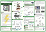
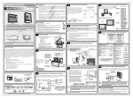
4
Before you begin...
®
Minimum items required to create a working system:
3505 HUTCHINSON ROAD
CUMMING, GA 30040-5860
• C-more Touch Panel - 6”, 8”, 10”, 12” or 15” model
• C-more Programming Software, p/n EA-PGMSW
• C-more USB Programming Cable, p/n USB-CBL-AB15 or Ethernet connectivity between PC and Touch Panel
• Power source: C-more AC/DC Power Adapter, p/n EA-AC or a dedicated 24 VDC (20.4 - 28.8 VDC) switching
power supply @ 1.5 A minimum
• Personal computer - to run the C-more programming software
• Communications Cable (serial or Ethernet) – to connect the C-more Touch Panel to your controller
Quick Start Guide
Base Feature
STN and TFT
displays
6” STN grayscale
EA7-S6M-R
6” grayscale
EA7-S6M
Full Feature
TFT displays
8
1
15
9
Pin
Signal
Pin
1
Frame GND
6
LE
Signal
Pin
11
Signal
2
TXD (232C)
7
CTS (232C)
12 TXD– (422/485)
3
RXD (232C)
8
RTS (232C)
13 Term. Resistor
TXD+ (422/485)
4
Future
9
RXD+ (422/485)
14 do not use
5
Logic GND
10 RXD– (422/485)
15 do not use
Setting
Adjust Clock
Adjust Display
Adjust Touch Panel
Beeper
Main Menu
Unpack and Inspect
MAIN MENU
Temporary
Support Stand
Ethernet 10/100 Base-T
PLC Communications,
Programming/Download
Audio Line Out,
stereo, 1 Volt rms,
3.5mm Mini Jack
(Amplifier Required)
Pin
Cutout Template
located here.
USB Port - Type B
Programming/Download
Mounting Clips
and DC power connector
located in here.
Pin
USB Port - Type A
USB Device Options
Signal
1
Vbus
2
D–
3
D+
4
GND
Pin
2
1
3
4
1 2 3 4
1
Vbus
2
D–
3
4
Shell Shield
Signal
Signal
Pin
Adjust Clock
Time
Signal
TD+
5
do not use
2
TD–
6
RD–
3
RD+
7
do not use
4
do not use
8
do not use
Test Menu
09 - 01 - 2005
Memory
12
Exit
8
Link Status LED (Green)
Date
10 : 45 : 23
1
1
Setting
Information
9
3
Network Activity LED (Orange)
D+
On
Ethernet Linked
On
Active Network Data
GND
Off
No Ethernet Comm.
Off
Network Idle
6
OK
Cancel
SHELL Shield
Note: Device is not available on Base Feature touch panels, part numbers EA7-S6M-R and EA7-T6CL-R.
6” color
EA7-T6CL
AC/DC Power Adapter
EA-AC
8” color
EA7-T8C
Expansion Assembly
EA-EXP-OPT
Note: Use USB Programming Cable, p/n USB-CBL-AB15.
9
10” color
EA7-T10C
Shipping Carton Contents
Full Feature
and very large
TFT displays
6“ & 8” Touch Panel – Temporary Stand
15” color
EA7-T15C
General Description
The C-more® series of Touch Panels provides excellent capabilities and expanded features with their enhanced graphical
programming software, rugged hardware, and convenient accessories. Engineered into the product design to provide excellent hardware and software are features such as those listed below. Some features are not available on the base feature panels.
• Analog touch screen (no touch cell boundaries)
• Plenty of memory and methods to get data in/out of the panel
• Overlapping active devices on the screen
• 65,536 colors for enhanced graphics
• Screen resolutions up to 1024 X 768 pixels
• Built-in project simulation, test on PC while developing
• Serial RS232, RS422/485 and Ethernet 10/100Base-T communications • Programming via USB or Ethernet (Ethernet on full feature only.)
• Optional AC/DC Power Adapter (EA-AC)
• User replaceable bezels on 8”, 10”, 12” & 15” panels
• Animation of bitmaps and objects
• PID face plate, trending, alarming and a recipe database
• 4,000 built-in symbols, classic fonts: 6x8, 8x16, 8x32, 8x64, 16x16, 16x32, 16x64, 32x16, 32x32, 32x64, and Windows fonts
• Event Manager to trigger actions based on assigned state changes, schedules, PLC tag names, etc., setup in a database environment.
The event can also trigger a sound byte, initiate a screen capture, send a data file (FTP), send an E-mail, etc.
• Select unique background for each screen
• Trend Data logging
• Built-in FTP client/server, E-mail client, and Web server
• Internet Remote Access
• Audio output port, stereo – requires amplifier and speaker(s)
2
1
3
4
Shipping Carton Packing Material
6
5
7
6
10”, 12“ & 15” Touch Panel – Temporary Stand
Accessories (sold separately)
CF Card Interface Module:
EA-CF-IF
CompactFlash
Memory Card:
EA-CF-CARD
3
Non glare 12 inch screen cover:
EA-12-COV2
(pk of 3)
PC
C-more
Touch Panel
4
6
5
Non glare 6 inch screen cover:
EA-6-COV2
(pk of 3)
Safety Information
WARNING: To minimize the risk of potential safety problems, you should follow all applicable local and national
codes that regulate the installation and operation of your equipment. These codes vary from area to area and it is your
responsibility to determine which codes should be followed, and to verify that the equipment, installation, and operation
are in compliance with the latest revision of these codes.
Equipment damage or serious injury to personnel can result from the failure to follow all applicable codes and standards. We
do not guarantee the products described in this publication are suitable for your particular application, nor do we assume any
responsibility for your product design, installation, or operation.
If you have any questions concerning the installation or operation of this equipment, or if you need additional
information, please call us at 1-800-633-0405 or 770-844-4200.
This publication is based on information that was available at the time it was printed. At Automationdirect.com we
constantly strive to improve our products and services, so we reserve the right to make changes to the products and/or
publications at any time without notice and without obligation. This publication may also discuss features that may not
be available in certain revisions of the product.
®
Ethernet
Port
3
Compact Flash
Memory Card
EA-CF-CARD
NOTE: CompactFlash memory
card designations – CF Slot #1
is at the top of the panel and
CF Slot #2 is the CF Card
Interface Module, p/n EA-CF-IF.
C-more
Touch Panel
CF card plugs
into slot #1
at top of panel
CF card interface
module installs
in right slot only,
left slot for future
✔
C
UL
R
US
Copyright 2005-2014, Automationdirect.com Incorporated/All Rights Reserved Worldwide
Productivity 3000
EA-90-30-CBL
MITSUBISHI FX Series 25-pin port
(RS-422A)
EA-MITSU-CBL
DL05/DL06
MITSUBISHI FX Series 8-pin mini-DIN
(RS-422A)
EA-MITSU-CBL-1
DL105
OMRON Host Link
C200 Adapter, C500
(RS-232C)
EA-OMRON-CBL
CLICK
all
H0-ECOM/H0-ECOM100
all
D2-230
D2-240
D2-250/D2-250-1/D2-260
NOTE: EZTouch serial PLC
communication cables are
compatible with C-more
touch panels.
EA-2CBL-1
D2-240/D2-250-1/D2-260
Using DCM
H2-ECOM/H2-ECOM100
D3-330/330P
(Requires the use of a Data
Communications Unit)
D3-340
AutomationDirect
DL305
Direct LOGIC
D3-350
DL405
D4-450
Ethernet
Port
H4-ECOM/H4-ECOM100
H2-WinPLC (Think & Do) Live V5.2 or later and
Studio any version
H2-WinPLC (Think & Do) Live V5.5.1 or later and
Studio V7.2.1 or later
(Bottom View)
DF1 Full Duplex
DF1 Half Duplex; DF1 Full Duplex
EtherNet/IP Server
EtherNet/IP Client
Modbus TCP/IP
SNPX
FX Direct
Q CPU
QnA Serial
QnA Ethernet
Host Link
FINS
Modbus RTU
PPI
ISO over TCP
AutomationDirect Prod. 3000 Serial
AutomationDirect Prod. 3000 Ethernet
AutomationDirect Modbus (CLICK)
K-Sequence
Direct NET
Modbus (Koyo addressing)
Direct LOGIC Ethernet
K-Sequence
K-Sequence
K-Sequence
Direct NET
K-Sequence
Direct NET
Modbus (Koyo addressing)
Direct NET
Modbus (Koyo addressing)
Direct LOGIC Ethernet
Direct NET
D4-440
10
7
NOTE: Refer to the individual
product data sheets that are
included with the accessories
for additional information.
Expansion Assembly
EA-EXP-OPT
AC/DC Power Adapter
EA-AC
Provide Power to the Touch Panel
• Wire a dedicated 24 VDC (20.4 - 28.8 VDC) power source rated at a
minimum of 1.5 Amps to the DC connector on the rear of the
C-more touch panel, include wiring the ground terminal to a
proper equipment ground. The recommended power supply is
AutomationDirect P/N: PS24-050D
• or install a C-more AC/DC Power Adapter, p/n EA-AC, to the rear
of the touch panel and wire an AC voltage source of 100-240 VAC,
50/60Hertz, to its AC connector
• then turn on the power source and check the LED status indicators
on the rear of the C-more touch panel for proper indication
DC Wiring
Recommended DC Supply Fuse
Panel Size Rating
6“ – 10”
2.5 A
12“ & 15”
4.0 A
ADC p/n
MDL2-5
MDL4
+
Serial
24 VDC, -15%, +20%
(20.4 - 28.8 VDC)
Direct NET
K-Sequence
Direct NET
Modbus (Koyo addressing)
Direct NET
Modbus (Koyo addressing)
K-Sequence
Direct NET
K-Sequence
Direct NET
K-Sequence
Direct NET
Modbus (Koyo addressing)
Direct NET
Modbus (Koyo addressing)
Direct LOGIC Ethernet
Think & Do Modbus RTU
(serial port)
Think & Do Modbus TCP/IP
(Ethernet port)
C-more
Touch Panel
Ethernet
Port
(Bottom View)
Ethernet CAT5
Cable - Crossover
DL06 PLC
Ethernet via
Hub or Switch
(such as SE-SW5U)
–
H0-ECOM/H0-ECOM100
Ethernet Module
PWR
Equipment
Ground
EA-AC
AC Wiring
Ethernet via Crossover Cable
H0-ECOM/H0-ECOM100
Ethernet Module
Stride™
Ethernet Switch
10/100 Base-T
C-more
Touch Panel
DL-06 PLC
CPU
USB Pen Drive
SDCZ4-2048-A10
Connect Touch Panel to PLC
• Connect the serial communications cable between
the C-more touch panel and the PLC
• or connect the C-more touch panel and PLC together via
an Ethernet hub or switch, and Ethernet cables (full feature
panels only)
• or use an Ethernet crossover cable directly between the
C-more Ethernet port and the PLC Ethernet port (full feature
panels only)
GND
BATT
Port 2
C-more
Touch Panel
1
C-more to
Direct LOGIC
VGA 15-pin port
serial cable
p/n EA-2CBL-1
Ethernet
Port
(Bottom View)
DL06 PLC
Serial Port Adapter
EA-ADPTR-4
AC Power Adapter
Not recommended for use with the EA7-T15C
when operating temperatures are expected
to be above 40 deg C.
KOYO ELECTRONICS INDUSTRIES CO., LTD.
C-more LED Status Indicators
Off
NOTE: The C-more 6” touch panels
will fit into the existing cutout of
any EZTouch 6” slim bezel panel.
Use the C-more 6” Adapter Plate,
p/n EA-6-ADPTR, to install C-more
6” panels into existing cutouts of
EZTouch 6” non-slim (rounded
bezel) panels.
Green
Power Off
PWR
Normal – CPU Run State
On
Power On
Off
Power Off
CPU
TxD
Serial Port Adapter
EA-COMCON-3
Red
Recommended AC Supply Fuse
3.0 A time delay, ADC p/n MDL3
Date code
Country of Origin
KOYO ELECTRONICS INDUSTRIES CO., LTD.
EA-COMCON-3
Ethernet CAT5
Cable - Straight-thru
WARNING: The AC/DC Power Adapter should not be
used with the EA7-T15C touch panel when operating
temperatures are expected to exceed 40 °C [104 °F].
Date code
Country of Origin
TERM
EN61131-2
Siemens
DF1 Half Duplex; DF1 Full Duplex
Ethernet CAT5
Cable - Straight-thru
RD+
234884
Modicon
EAPLC5-232-CBL
GE 90/30, 90/70, Micro 90,
VersaMax Micro
15-pin D-sub port (RS-422A)
Ethernet
Port
C-more
Touch Panel
1
CF Card
Interface Module
EA-CF-IF
RD–
Per file #
E157382
Omron
Ethernet via
Hub or Switch
(such as SE-SW5U)
Install Optional Hardware Accessories (sold separately)
SD+
E157382
Allen-Bradley SLC 5-03/04/05,
ControlLogix, CompactLogix, FlexLogix, EA-SLC-232-CBL
DF1 port (RS-232C)
D4-430
Ethernet
Port
SD–
C-more Touch Panels &
Accessories
Mitsubishi
All with DCM
GND
ISO-9000
EA-MLOGIX-CBL
Modbus TCP/IP
GE
DL205
Power LED (Green)
CE
Allen-Bradley MicroLogix 1000, 1100,
1200, 1400, 1500 (RS-232C)
(Bottom View)
CPU Status LED (Green, Orange & Red)
CSA
EA-4CBL-2
Ethernet CAT5
Cable - Crossover
Stride™
Ethernet Switch
10/100 Base-T
USB Port – Type B
Programming/Download
UL/CUL/CSA/CE Certification Numbers
UL508
Direct LOGIC PLC 25-pin D-sub port,
DL405, D3-350, DL305 DCU and
all DCM’s (RS-232C)
PC
EA-ADPTR-4
UL/CUL
Direct LOGIC DL405 PLC 15-pin D-sub EA-4CBL-1
port, DL405 (RS-232C)
PC
IOIOI – PLC
Name
EA-3CBL
Allen-Bradley MicroLogix, SLC
5-01/02/03, PLC5 DH485 port (RS-232C) EA-DH485-CBL
C-more
Touch Panel
USB-CBL-AB15
6” Adapter Plate
EA-6-ADPTR
Agency Approvals
Direct LOGIC PLC RJ-11 port, D3-340
(RS-232C)
Ethernet via
Crossover Cable
USB Port –
Type A
Non glare 10 inch screen cover:
EA-10-COV2
(pk of 3)
USB Pen Drive,
2 GB:
SDCZ4-2048-A10
EA-2CBL-1
DH485/AIC/AIC+
D3-350 DCM
USB
Non glare 8 inch screen cover:
EA-8-COV2
(pk of 3)
NOTE: To check your
computer system
information, go to
the Start Menu –
All Programs and
select Accessories,
then System Tools,
and finally System
Information.
Direct LOGIC (VGA Style) 15-pin port
DL06, D2-250 (250-1), D2-260
(RS-232C)
Allen-Bradley
Protocols
MicroLogix 1000, 1100, 1200, 1400, 1500,
SLC 5-01/02/03, PLC5
MicroLogix 1000, 1100, 1200, 1400, 1500
SLC 5-03/04/05
ControlLogix™, CompactLogix™, FlexLogix™
PLC-5
ControlLogix, CompactLogix, FlexLogix - Tag Based
ControlLogix, CompactLogix, FlexLogix Generic I/O Messaging
ControlLogix, CompactLogix, FlexLogix - Tag Based
MicroLogix 1100, 1400, SLC 5/05,
both via native Ethernet port
MicroLogix 1000, 1100, 1200,1400, 1500,
SLC 5-03/04/05, all via ENI Adapter
Modbus TCP/IP devices
90/30, 90/70, Micro 90, VersaMax Micro
FX Series
Q02, Q02H, Q06H, Q12H, Q25H
Q, QnA Serial
Q, Qna Ethernet
C200 Adapter, C500
CJ1/CS1 Serial; CJ1/CS1 Ethernet
984 CPU, Quantum 113 CPU, AEG Modicon Micro
Series 110 CPU: 311-xx, 411-xx, 512-xx, 612-xx
S7-200 CPU, RS-485 Serial
S7-200 CPU, S7-300 CPU; Ethernet
Productivity3000 Serial (P3-550)
Productivity3000 Ethernet (P3-550)
all
Insert tabs
between layers
Non glare 15 inch screen cover:
EA-15-COV2
(pk of 3)
D-SUB 15 pin to
Terminal Block Adapter:
EA-COMCON-3
Cable
Part Number
AutomationDirect CLICK, Direct LOGIC
PLC RJ-12 port, DL05, DL06, DL105,
DL205, D3-350, D4-450 & H2-WINPLC EA-2CBL
(RS-232C)
Connect Touch Panel to Computer
• Connect a USB Programming Cable, p/n USB-CBL-AB15, from
a USB port type A on the PC to the USB type B programming
port on the C-more touch panel
• or connect the C-more touch panel and PC together
via an Ethernet hub or switch, and Ethernet cables (full
feature panels only)
• or use an Ethernet crossover cable directly between the
C-more touch panel Ethernet port and the PC Ethernet port
(full feature panels only)
Shipping Carton Packing Material
D-SUB 15 pin 90 degree
Comm Port Adapter:
EA-ADPTR-4
Purchased Cable
Description
Model
8
2
Expansion Assembly:
EA-EXP-OPT
Install the Software and Develop a Project
Insert the supplied CD-ROM into the PC’s CD-ROM drive and follow the instructions. If you
need assistance during the software installation, please refer to the supplied Software Installation
Guide or call the AutomationDirect Technical Support team @ 770-844-4200.
1
6 inch Adapter Plate:
EA-6-ADPTR
(Used to retrofit new
C-more 6” touch panel
into existing EZTouch
non-slim panel cutout.)
PLC Compatibility Table
Allen-Bradley PLC-5
DF1 port (RS-232C)
A table of complete specifications for all touch panels is located on the back of this Quick Start Guide. Touch
Panel and accessory dimension and mounting information is also located on the back. Please refer to the individual
data sheet inserts that are included with each accessory for additional details.
AC/DC Power Adapter:
EA-AC
5
• Personal Computer with a 333 MHz or higher processor (CPU) clock speed recommended; Intel® Pentium/
Celeron family, or AMD® K6/Athlon/Duron family, or compatible processor recommended
• Keyboard and Mouse or compatible pointing device
• Super VGA color video adapter and monitor with at least 800 x 600 pixels resolution
(1024 x 768 pixels recommended)
64K color minimum
• 300 MB free hard-disk space
• 128 MB free RAM (512 MB recommended); 512 MB free RAM (1 GB recommended) for Vista
• CD-ROM or DVD drive for installing software from the CD
• USB port or Ethernet 10/100 Mbps port for project transfer from software to touch panel (Ethernet port not
available on -R models)
• Operating System - Windows® XP Home / Professional Edition Service Pack 2 (32 bit), Windows 2000 with
Service Pack 4, Windows Vista® (32 or 64 bit) or Windows 7 (32 or 64 bit)
Assemble Temporary Support Stand
Touch Panel to PLC Communication Protocols & Cables
PLC Family
Following are the minimum system requirements for running C-more Programming Software,
p/n EA-PGMSW, on a PC:
2
12” color
EA7-T12C
CF
PLC Serial Communications
For Future Use
• Unpack the C-more Touch Panel from its shipping carton. Included in
the carton is the C-more Touch Panel, cutout template, mounting clips,
temporary support stand, DC power connector, gasket, and this Quick
Start Guide.
• Unpack any accessories that have been ordered, such as:
AC/DC Power Adapter, Expansion Assembly, CompactFlash memory,
programming cable, communications cable, etc.
• Inspect all equipment for completeness. If anything is missing or
damaged, immediately call the AutomationDirect® returns
department @ 1-800-633-0405.
Full Feature
STN displays
Compact Flash
memory slot #1
is located at the
top of panel.
Accessing the Touch Panel Setup Screens
• Access the Main Menu of the touch panel setup screens by pressing the extreme upper left
corner of the panel display area for three (3) seconds as shown below.
• Adjust the time and date for the panel by pressing the Setting button on the Main Menu,
then press the Adjust Clock button on the Setting screen.
• Use the right pointing arrows for the time or date display to select the unit to change. Use
the up and down arrows to increment or decrement the value for the selected unit.
• Press OK when done to accept the changes to the time and date that is retained in the
touch panel’s battery backed memory, or press Cancel to exit the Adjust Clock setup
screen without making any changes.
• Press the Main Menu button on the Setting screen and then the Exit button on the Main
Menu screen to return to the application screen.
Bottom View
1
6” TFT color
EA7-T6CL-R
8
Available Communication Ports
Blinking
Red
Blinking
Orange
Blinking
Green
100 - 240 VAC
50/60 Hz
Tightening Torque
Power supply cable torque
71 - 85 oz-in (0.5 - 0.6 Nm)
Mounting flange screw torque 57 - 71 oz-in (0.4 - 0.5 Nm)
Memory Error
RxD
BATT
Operating System not found
LCD Backlight Failure
Serial TxD/RxD LED (Green)
IOlOl–PLC
Power Loss Detection
On Comm. is active
Off No communication
Rear View
Additional Help and Support
• For product support, specifications, and installation troubleshooting, a Hardware User Manual can be
downloaded from the On-line Documentation area of the AutomationDirect Web site or
purchased through the AutomationDirect Sales team @ 1-800-633-0405 as part number EA-USER-M.
• For software programming help, refer to the C-more Programming Software on-line embedded help.
• Refer to demos of the product at: http://c-more.automationdirect.com/software/software_demo.html
• For additional technical support and questions, call our Technical Support team @ 1-800-633-0405 or
770-844-4200.
Data Sheet: EA-QSG, Rev. P
Model
Specification
6” STN grayscale
w/ base features
6” TFT color
w/ base features
6” STN grayscale
w/ full features
6” TFT color
w/ full features
8” TFT color
w/ full features
10” TFT color
w/ full features
12” TFT color
w/ full features
15” TFT color
w/ full features
EA7-S6M-R
EA7-T6CL-R
EA7-S6M
EA7-T6CL
EA7-T8C
EA7-T10C
EA7-T12C
EA7-T15C
5.7” STN grayscale
15 shades of gray
5.7” TFT color
65,536 colors
5.7” STN grayscale
15 shades of gray
5.7” TFT color
8.4” TFT color
10.4” TFT color
65,536 colors
12.1” TFT color
15.0” TFT color
6.73” x 5.05”
[170.9 mm x 128.2 mm]
8.31” x 6.24”
[211.2 mm x 158.4 mm]
9.47” x 7.62”
[240.6 mm x 184.5 mm]
11.97” x 8.98”
[304.1 mm x 228.1 mm]
Part Number
Display Actual Size and Type
Color Scale
Display Viewing Area
4.54” x 3.4” [115.2 mm x 86.4 mm]
Screen Pixels
Display Brightness
LCD Panel Dot Pitch
Backlight Average Lifetime*1
Backlight User Replaceable
Touch Panel Type
320 x 240 (QVGA)
2
640 x 480 (VGA)
2
150 cd/m (NITS)
2
270 cd/m (NITS)
150 cd/m (NITS)
0.36 mm x 0.36 mm
CPU Type
2
2
270 cd/m (NITS)
300 cd/m (NITS)
0.267 mm x 0.267 mm
Approximately 50,000 hours
No
Analog Resistive (10-bit resolution, 1024 x 1024 touch area)
32-Bit RISC CPU (333 MHz)
Battery
System Memory
System Flash Memory
Backup Memory (SRAM)
Logging Data Memory
Number of Screens
Realtime Clock
Calendar – Month/Day/Year
Screen Saver
Serial PLC Interface
USB Port – Type B
USB Port – Type A
Ethernet Port
Audio Line Out
CF Card – Slot #1
Expansion Assembly
(p/n EA-EXP-OPT)
Supply Power
Power Consumption
Recommended DC Supply Fuse
Operating Temperature
Storage Temperature
Humidity
Noise Immunity
Withstand Voltage
Insulation Resistance
Vibration
Shock
Environment
Enclosure
Agency Approvals
USB Pen Drive p/n SDCZ4-2048-A10 (Optional)
not available
not available
not available
2
270 cd/m (NITS)
0.33 mm x 0.33 mm
7.402
[188.0]
Gasket
1.500
[38.1]
0.197
[5.0]
6.140
[156.0]
5.458
[138.6]
32-Bit RISC CPU (400 MHz)
Plus Graphic Accelerator Chip
Replaceable battery – ADC Part # D2-BAT-1 (Manufacturer Part # CR2354)
SDRAM 32 MBytes
SDRAM 64 MBytes
FLASH 32 MBytes
FLASH 64 MBytes
Control data backup memory (SRAM) 256 KBytes
CompactFlash Memory Card p/n EA-CF-CARD, industrial grade, high speed (Optional) or USB Pen Drive p/n SDCZ4-2048-A10 (Optional)
Up to 9999 with ver. 2.40 and later – limited by available project memory (10 MBytes)
Up to 9999 with ver. 2.40 and later – limited by available project memory (40 MBytes)
Built into panel (PLC clock is still accessible if available)
Yes - battery backup
Yes, backlight turns off after a 30–1500 minute adjustable time, or can be disabled
Serial PLC Port: RS-232C/422/485 15-Pin D-sub (female)
Download/Program – USB Port – type B
Port for USB 1.1 device options – type A
Ethernet 10/100 Base-T
Audio Line Out, 1 Volt rms, stereo – requires amplifier and speaker(s)
Optional: CompactFlash Memory Card p/n EA-CF-CARD, CF slot #1 located on top side of touch panel.
1.46 lb. [660 g]
1.43 lb. [650 g]
1.48 lb. [670 g]
1.50 lb. [680 g]
2.60 lb. [1,180 g]
3.55 lb. [1,610 g]
4.59 lb. [2,080 g]
11.820
[300.2]
Gasket
Gasket
1.738
[44.1]
1.685
[42.8]
Units: inches[mm]
0.315
[8.0]
NOTE: The C-more
10” touch panel will
fit into the existing cutout of any
EZTouch 10” touch
panel.
Mounting Clip
(6) places
10.894
[276.7]
8.748
[222.2]
0.394
[10.0]
Units: inches [mm]
13.661
[347.0]
Mounting Clip
(6) places
6.993
[177.6]
10.669
[271.0]
8.828
[224.2]
NOTE: The C-more 8” touch
panel will fit into the existing
cutout of any EZTouch 8” touch
panel.
15” Touch Panel Dimensions – EA7-T15C
14.892
[378.3]
12” Touch Panel Dimensions – EA7-T12C
Gasket
1.654
[42.0]
12.430
[315.7]
NOTE: The C-more
15” touch panel will
fit into the existing cutout of any
EZTouch 15” touch
panel.
Units: inches[mm]
16.748
[425.4]
9 W @ 24 VDC
Dimensions
10” Touch Panel Dimensions – EA7-T10C
9.159
[232.6]
NOTE: The C-more 6” touch
panels will fit into the existing cutout of any EZTouch 6”
slim bezel panel. Use the
C-more 6” Adapter Plate,
EA-6-ADPTR, to install
C-more 6” panels into existing cutouts of EZTouch 6”
non-slim (rounded bezel)
panels.
0.394
[10.0]
Optional: Use the CF Card Interface Module p/n EA-CF-IF in the right slot of the Expansion Assembly for installing CF card - Slot #2. The left slot of the Expansion Assembly is for future options.
8” Touch Panel Dimensions – EA7-T8C
EA7-S6M-R
EA7-T6CL-R
EA7-S6M
EA7-T6CL
8.047
[204.4]
24 VDC, -15%, +20% (20.4–28.8 VDC operating range p/n PS24-050D) (Use an AC Power Adapter, p/n EA-AC, to power the touch panel from a 100-240 VAC, 50/60 Hz. power source.)
10 W @ 24 VDC
11 W @ 24 VDC
15 W @ 24 VDC
17 W @ 24 VDC
20 W @ 24 VDC
33 W @ 24 VDC
2.5 A time delay, ADC p/n MDL2-5
4.0 A time delay, ADC p/n MDL4
0 to 50 °C (32 to 122 °F); Maximum surrounding air temperature rating: 50 °C (122 °F)
–20 to +60 °C (–4 to +140 °F)
10–85% RH, non-condensing
Noise voltage: 1000 Vp-p, Pulse width: 1 µs, Rise time: 1 ns
1000 VDC for 1 minute, between DC power supply input terminal and safety ground
Over 20 M⏲ between DC power supply input terminal and safety ground
IEC61131-2 compliant, 10–57 Hz: 0.075 mm amplitude, 57–150 Hz 1.0 G: 10 sweep cycles per axis on each of 3 mutually perpendicular axes
15 G peak, 11 ms duration, 2 shocks per axis, on 3 mutually perpendicular axes
For use in Pollution Degree 2 Environment
Meets UL Type 4X, when mounted correctly. For indoor use only.
UL, cUL, CE
8.748” x 10.894” x 2.053”
10.669” x 13.661” x 2.079”
11.024” x 13.366” x 2.075”
13.000” x 16.748” x 2.048”
6.140” x 8.047” x 1.697” [156.0 mm x 204.4 mm x 43.1 mm]
[222.2 mm x 276.7 mm x 52.1 mm]
[271.0 mm x 347.0 mm x 52.8 mm]
[280.0 mm x 339.5 mm x 52.7 mm]
[330.2 mm x 425.4 mm x 52.0 mm]
9 W @ 24 VDC
Mounting Clip
(2) places
Units: inches[mm]
1024 x 768 (XGA)
220 cd/m2 (NITS)
0.297 mm x 0.297 mm
Analog Resistive (12-bit resolution, 4096 x 4096 touch area)
32-Bit RISC CPU (400 MHz)
not available
Weight
800 x 600 (SVGA)
260 cd/m2 (NITS)
0.267 mm x 0.267 mm
6” Touch Panel Dimensions
1.681
[42.7]
0.394
[10.0]
Mounting Clip
(8) places
Units: inches [mm]
Mounting Clip
(6) places
13.366
[339.5]
11.230
[285.2]
13.000
[330.2]
Gasket
10.088
[256.2]
11.024
[280.0]
7.01 lb. [3,180 g]
* NOTE 1: The backlight average lifetime is defined as the average usage time it takes before the brightness becomes 50% of the initial brightness. The lifetime of the backlight depends on the ambient temperature. The lifetime will decrease under low or high temperature usage.
EA7-S6M-R
EA7-T6CL-R
EA7-S6M
EA7-T6CL
7.460 +0.04
-0.0
[189.5 +1.0
-0.0]
0.630
[16.0]
Mounting Clip
Screw Torque
0.315
[8.0]
0.294
[7.5]
0.294
[7.5]
5.512 +0.04
-0.0
[140.0 +1.0
-0.0 ]
NOTE: The C-more 6” touch
panels will fit into the existing cutout of any EZTouch 6”
slim bezel panel. Use the
C-more 6” Adapter Plate,
p/n EA-6-ADPTR, to install
C-more 6” panels into existing cutouts of EZTouch 6”
non-slim (rounded bezel)
panels.
Enclosure Mounting Thickness Range
and Mounting Clip Screw Torque
Mounting Clip
(2) places
0.315
[8.0]
Enclosure Mounting
Thickness Range
CUTOUT
Bezel Outline
Touch
Panel Size
Enclosure
Thickness Range
Mounting Clip
Screw Torque
6” – lower mounting
clip position
0.039 - 0.24 inch
[1 – 6 mm]
35 ~ 50 oz-in
[0.25 ~ 0.35 Nm]
6” – upper mounting
clip position
0.20 - 0.63 inch
[5 – 16 mm]
35 ~ 50 oz-in
[0.25 ~ 0.35 Nm]
8”, 10”, 12” & 15”
0.039 - 0.20 inch
[1 – 5 mm]
42 ~ 57 oz-in
[0.3 ~ 0.4 Nm]
Mounting
Clearances
0.630
[16.0]
6.533
[165.9]
0.709
[18.0]
0.118 ±0.04
[3.0 ±1.0]
7.299
[185.4]
M4
Thread
Insert
(6 places)
Adapter
Front View
14.960 +0.04
-0.0
[380.0 +1.0
-0.0 ]
7.480
[190.0]
0.894
[22.7]
0.406
[10.3]
Screw
NOTE: Refer to the product data
sheet, EA-6-ADPTR-DS, that is
included with the adapter plate
for additional information.
C-more
Adapter Plate
11.276 +0.04
-0.0
[286.4 +1.0
-0.0 ]
CUTOUT
7.075 +0.04
-0.0
[179.7 +1.0
-0.0 ]
5.624
[142.8]
3.111
[79.0]
Units: inches[mm]
Product Label
EA-CF-IF
3.024
[76.8]
1.618
[41.1]
2.067
[52.5]
Enclosure
Units: inches [mm]
EA-CF-IF
Units: inches [mm]
Connector Cover
NOTE: The CF Card Interface
Module must be installed in
the right slot of the Expansion
Assembly. Refer to the product
data sheet, EA-CF-IF-DS, that
is included with the module for
additional information.
DIN Mounting
Clips
2.812
[71.4]
3.761
[95.5]
5.638
[143.2]
BOTTOM VIEW
0.780
[19.8]
2.122
[53.9]
3.567
[90.6]
Cutout Outline
3.537
[89.9]
Units: inches [mm]
0.579
[14.7]
Two sets of mounting screws provided:
Set A - M4-8 metric screws for an enclosure
thickness range of 0.02-0.118 inch [0.5-3mm]
Set B - M4-10 metric screws for an enclosure
thickness range of 0.118-0.197 inch [3-5mm]
Mounting screw torque: 100 oz-in [0.7 Nm]
Centerline
6.222
[158.0]
0.837
[21.3]
NOTE: Refer to the product
data sheet, EA-AC-DS, that
is included with the power
adapter for additional
information.
Expansion Assembly Dimensions
EA-EXP-OPT
6“ C-more
Touch Panel
0.837
[21.3]
1.421
[36.1 ±0.5]
2.165
[55.0]
Adapter Plate
Outline
0.218 Dia.
[5.5]
(6 places)
CF Card Interface Module
Dimensions
Rear View
Mounting Details
2.125
[54.0]
0.864
[21.9]
DC Power
Connector
SIDE VIEW
Units: inches [mm]
Gasket
Cutout Dimensions
0.394
[10.0]
CUTOUT
Units: inches [mm]
FRONT VIEW
Side View
8.076
[205.1]
4.250
[108.0]
Mounting Clip
(6) places
Cutout Outline
6.223 ±0.02
[158.1 ±0.5]
Centerline
NOTE: The adapter plate has been designed to simplify the retrofit of a new C-more
6” touch panel into an existing cabinet cutout for an EZTouch 6” non-slim touch
panel, such as our part number EZ-S6C-K, EZ-S6C-F, EZ-S6M-R or EZ-S6M-F. The new
C-more 6” touch panel will directly mount into the existing cutout opening for any
EZTouch 6” slim touch panel. The adapter plate gasket is included.
0.395
[10.0]
Mounting Clip
(8) places
CUTOUT
NOTE: The AC/DC Power Adapter allows Power Fault features
to help protect data being logged to CompactFlash during
power failures. The C-more touch panel must have firmware
version 1.21 Build 6.18E or higher for proper operation.
±0.02
0.395
[10.0]
0.822
[20.9]
WARNING: The AC/DC Power Adapter should not by used with
the EA7-T15C touch panel when operating temperatures are
expected to exceed 40 °C [104 °F].
3.661
[93.0]
AC Power
Connector
NOTE: The mounting clearances when installing the touch panel in an enclosure or cabinet should be kept to a minimum of 4 inches
from the top, bottom and sides and 2 inches from the rear.
0.394
[10.0]
4.625
[117.5]
AC Power Label
Screw
3.001
[76.2]
0.709
[18.0]
6” Touch Panel Cutout
9.250 +0.04
-0.0
[235.0 +1.0
-0.0]
AC/DC Power Adapter Dimensions – EA-AC
8.076 ±0.02
[205.1 ±0.5]
4.250 ±0.02
[108.0 ±0.5]
0.618
[15.7]
Units: inches[mm]
Units: inches[mm]
0.822
[20.9]
Bezel Outline
8.932
[226.9]
Cutout Outline
0.894
[22.7]
0.394
[10.0]
6” Adapter Plate Dimensions – EA-6-ADPTR
0.705
[17.9]
0.837
[21.3]
7.522
[191.1]
0.705
[17.9]
NOTE: Refer to the product
data sheet, EA-EXP-OPTDS, that is included with
the expansion assembly for
additional information.
Screw Torque: 100 oz-in [0.7 Nm]
0.459
[11.7]
Bezel Outline
Screw
Replacement Parts
0.354
[9.0]
8 - 15 inch mounting clips:
EA-BRK-2
(pk of 8)
0.394
[10.0]
DC power connector:
EA-DC-CON
Mounting Clip
(6) places
CUTOUT
0.394
[10.0]
AC power connector:
EA-AC-CON
12 inch backlight:
EA-12-BULB
EA-12-BULB2
10 inch backlight:
EA-10-BULB
EA-10-BULB2
8 inch backlight:
EA-8-BULB
EA-8-BULB2
10.236
[260.0
8.917 +0.04
-0.0
[226.5 +1.0
-0.0 ]
Cutout Outline
Units: inches [mm]
4.459
[113.2]
Units: inches [mm]
5.118
[130.0]
]
*CAUTION - The battery used in this device may present a risk of fire or chemical burn if mistreated. Do not recharge, disassemble, heat
above 100 °C (212 °F) or incinerate. Replace battery with AutomationDirect part number D2-BAT-1 or CR2354 only. Use of another battery
may present a risk of fire or explosion. Dispose of used battery properly. Keep away from children.
Cutout Outline
Bezel Outline
Units: inches[mm]
EA7-S6M = 2.921 [74.2]
EA7-T6CL = 2.921 [74.2]
EA7-T8C = 3.157 [80.2]
EA7-T10C = 3.106 [78.9]
EA7-T12C = 3.102 [78.8]
EA7-T15C = 3.075 [78.1]
X.XXX
[XX.X]
Units: inches[mm]
15-Pin Serial Port Adapters - Dimensions
6 inch Adapter Plate
replacement gasket
EA-6-ADPTR-GSK
+0.04
-0.0
+1.0
-0.0
with Expansion
Assembly,
EA-EXP-OPT
EA7-S6M-R = 2.921 [74.2]
EA7-T6CL-R = 2.921 [74.2
EA7-S6M = 2.921 [74.2]
EA7-T6CL = 2.921 [74.2]
EA7-T8C = 3.157 [80.2]
EA7-T10C = 3.106 [78.9]
EA7-T12C = 3.102 [78.8]
EA7-T15C = 3.075 [78.1]
6 - 15 inch Bezels:
EA-6-BEZEL
EA-8-BEZEL
EA-10-BEZEL
EA-12-BEZEL
EA-15-BEZEL
(gasket not included)
Note: 6 inch bezel is
not user replaceable.
CUTOUT
with AC/DC Power
Adapter, EA-AC
NOTE: The EA-ADPTR-4 adapter
is plugged into the 15-pin serial
port on the rear of the panel
to allow a PLC communication
cable to be plugged in at a 90
degree angle to reduce panel
depth requirements.
NOTE: The EA-COMCON-3 adapter is
plugged into the 15-pin serial port
on the rear of the panel to allow wire
terminal connections for RS-422/485
PLC communication cable.
Date code
Country of Origin
KOYO ELECTRONICS INDUSTRIES CO., LTD.
EA-COMCON-3
Date code
1.605
[40.8]
0.394
[10.0]
X.XXX
[XX.X]
6 - 15 inch gaskets:
EA-6-GSK
EA-8-GSK
EA-10-GSK
EA-12-GSK
EA-15-GSK
TERM
6 inch mounting clips:
EA-BRK-1
(pk of 2)
15 inch backlight:
EA-15-BULB
EA-15-BULB2
RD+
]
Touch Panel Overall Depth with Accessories Installed
Battery:
D2-BAT-1
RD–
0.354
[9.0]
6.289
[159.7]
0.394
[10.0]
0.877
[22.3]
0.876
[22.3]
Mounting Clip
(6) places
12.579
[319.5
+0.04
-0.0
+1.0
-0.0
0.406
[10.3]
SD+
0.394
[10.0]
]
5.954
[151.2]
0.877
[22.3]
0.354
[9.0]
0.864
[21.9]
SD–
11.908
[302.5
15” Touch Panel Cutout – EA7-T15C
GND
0.394
[10.0]
+0.04
-0.0
+1.0
-0.0
0.837 0.394
[21.3] [10.0]
1.756
[44.6]
8” Touch Panel Cutout – EA7-T8C
Country of Origin
KOYO ELECTRONICS INDUSTRIES CO., LTD.
EA-ADPTR-4
Perchlorate Material, special disposal handling may apply.
Bezel Outline
10” Touch Panel Cutout – EA7-T10C
0.876
[22.3]
0.394
[10.0]
12” Touch Panel Cutout – EA7-T12C
0.394
[10.0]
0.354
[9.0]
AVERTISSEMENT : La pile utilisée dans ce dispositif pourrait présenter un risque d’incendie ou de brûlure chimique si traitée inadéquatement. Ne pas recharger la pile, ne pas la démonter, ne pas la chauffer au-delà de 100 °C (212 °F) ni l’incinérer. Remplacez la pile
uniquement par la pièce n° D2-BAT-1 (CR2354) d’AutomationDirect.com. L’emploi de toute autre pile peut présenter un risque d’incendie
ou d’explosion. Jeter la pile usagée adéquatement. Tenir hors de portée des enfants.
IOIOI – PLC
1.873
[47.6]
1.126
[28.6]
EA-COMCON-3
R
1.873
[47.6]
0.793
[20.2]
EA-ADPTR-4
R