1
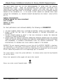
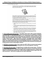
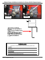
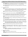
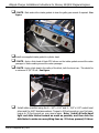
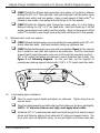
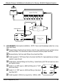
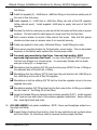
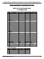
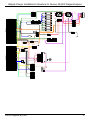
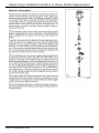
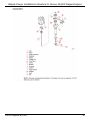
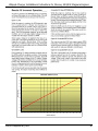
Whipple Charger Installations Instructions for Mercury 454/502 Magnum Engines Whipple Superchargers 93’-01’ 454/502 Magnum Installation Instructions Version A1R9 Last Updated April 1st, 2010 454/502 MagnumTBI_A1R9 1 Whipple Charger Installations Instructions for Mercury 454/502 Magnum Engines MUST KNOW INFORMATION!! -EVERYBODY READ!!- WATER FLOW – WATER FLOW – WATER FLOW As of May 2002, Mercury Racing issued a service bulletin (attached to instructions) regarding engine water block pressure. In this bulletin, it’s clear that Mercury Racing requires a minimum of 20-30lbs. of engine water pressure at wide-open throttle (WOT). If this pressure is not achieved or not maintained, you can have catastrophic engine failure of many types. This leads us to your new supercharged engine. You’re no longer running a thermostat in the engine, which was the largest water restriction in the stock system. Now, the largest restriction is the engine itself, this means pressure is only increased by flow in this given application. Because you are taking your stock engine and increasing the cylinder pressure for more peak power, to insure reliability, you need more water to keep the engine cool and at the same time, you need more water pressure to keep steam pockets from developing in your engine. With this in mind, you want a minimum of 25lpsi of block pressure @ WOT, maximum 40psi @ WOT. If you do not have this pressure, you may hurt your engine. Whipple Superchargers has provided a stainless restrictor for the thermostat housing that will restrict the flow like a thermostat, but pressure still must be checked, as this may be too much restriction (ideally) or not enough (means you need more). With this information in mind, you must understand, you must have more flow as well as pressure, if you restrict the outlet water too much and don’t have proper flow, you will heat the engine up, still develop steam pockets and it could lead to engine failure. • • • • • • • Ideally, the intercooler should be fed from a separate source. The intercooler does not need constant water flow at slow speeds. This means a separate pickup can be installed solely for the intercooler. You can run the intercooler off the drive side draft inlets, but never the engine. Mercury dual style water pickups do not let more water in, in fact, they have less water flow. Always block off the side draft inlets if your boat uses them on this dual style drives. Never run the engine off side draft inlets in the drive, never! If you have a stepped bottom or high “X” dimension, water flow may be very low at high speeds and caution must be taken. Test block pressure at various trim angles and in turns. Lower boost and or timing does not mean you’re safer with less water, if steam develops, the engine will fail regardless, it needs pressure to push the steam out. WATER FLOW – WATER FLOW – WATER FLOW 454/502 MagnumTBI_A1R9 2 Whipple Charger Installations Instructions for Mercury 454/502 Magnum Engines WHIPPLE CHARGER INSTALLATION INSTRUCTIONS 454/502 MAGNUM MPI STAGE 1 This product is intended for use on STOCK, UNMODIFIED, WELL-MAINTAINED ENGINES. Installation on a worn-out engine is not recommended and could result in failure of the engine or the supercharger. It is recommended to perform a compression test of all cylinders, and perform a cylinder pressure leak down procedure, check and change spark plugs, spark plug wires, distributor cap, and rotor if necessary. This will indicate the condition of the engine for reference. Whipple also recommends accurate fuel pressure and water block pressure gauges for constant monitoring during operation. This system is designed around the Delphi MEFI 3 and 4 ECM systems. If you have a MEFI 1, you will need a new ECM and you’ll have to modify the harness at the end of the instructions. It’s a good idea to review this as you may want to modify this during the middle of the installation. It is the purchaser’s responsibility to follow all installation instruction guidelines and safety procedures supplied with the product as it is received by the purchaser to determine the compatibility of the product with the vessel or the device the purchaser intends to install the product on. Whipple Supercharger assumes no responsibility for damages occurring from accident, misuse, abuse, improper installation, improper operation, lack of reasonable care, or all previously stated reasons resulting from incompatibility with other manufacturers’ products. **NOTICE: Installation of Whipple Supercharger products signifies that you have read this document and have agreed to the terms stated within. It is the purchaser’s responsibility to follow all installation instruction guidelines and safety procedures supplied with the product as it is received by the purchaser to determine the compatibility of the product with the vessel or the device the purchaser intends to install the product on. Whipple Supercharger assumes no responsibility for damages occurring from accident, misuse, abuse, improper installation, improper operation, lack of reasonable care, or all previously stated reasons resulting from incompatibility with other manufacturers’ products. There are no warranties expressed, implied, for merchantability or fitness for engine failure, parts failure, any type of damage to vessel in any way, or reimbursement for labor or inconvenience. 454/502 MagnumTBI_A1R9 3 Whipple Charger Installations Instructions for Mercury 454/502 Magnum Engines YOU MUST SEND YOUR ECU IN FOR REPROGRAMMING TO WORK WITH THE WHIPPLE SUPERCHARGER SYSTEM. THERE ARE REPLACEMENT ECU’S AVAILABLE. ACCOMPANY EACH COMPUTER WITH NAME, SHIPPING INFORMATION, CONTACT INFO, BOAT INFO AND IF ANY MODIFICATIONS HAVE BEEN MADE TO THE ENGINE. WHIPPLE WILL PAY FOR STANDARD GROUND FREIGHT IN THE CONTINETAL U.S. IF YOU WANT FASTER SERVICE OR SHIPPING FROM FROM OUTSIDE THE CONTINENTAL U.S., PROVIDE PAYMENT INFORMATION FOR FREIGHT. SEND FACTORY ECU TO: WHIPPLE SUPERCHARGERS ATTENTION: MARINE ECU RECAL DEPARTMENT 3292 N. WEBER FRESNO, CA 93722 559.442.1261 For best performance and continued reliability the following are MANDATORY. 1. USE ONLY PREMIUM GRADE FUEL (91 OCTANE OR BETTER). NEVER USE LOWER OCTANE. 2. ALWAYS LISTEN FOR ANY SIGN OF ENGINE KNOCKING, IF PRESENT DISCONTINUE USE IMMEDIATELY. 3. DO NOT OPERATE ENGINE IN BOOST IF THE FUEL PRESSRUE IS BELOW THE PRESSURE SPECIFIED BY WHIPPLE INDUSTRIES. 4. NEVER CHANGE THE WHIPPLE COMPUTER CALIBRATION PROGRAM (ENGINE RUN FUEL, IGNITION TIMING OR THE RPM LIMITER, NOTHING!) THIS COMPLETE SUPERCHARGER SYSTEM IS DESIGNED AND ENGINEERED TO MAXIMUM PERFORMANCE FROM THE WHIPPLE CALIBRATION. ANY MODIFICATIONS TO PROGRAM MAY CAUSE SERIOUS DAMAGE TO THE ENGINE. WARNING! The most important precaution you must take with the WHIPPLE CHARGER is cleanliness. This supercharger is a high quality, close tolerance compressor that cannot be subjected to dirt or any type of foreign material. Foreign material entering the supercharger will automatically void all warranties. DO NOT remove the protective seal on the supercharger prior to installation. This system requires a major fuel system modification. Use extreme caution around the high flammable fuel and fuel vapors. Always wear appropriate safety goggles and gloves when required. Always use caution around flammable liquids. 454/502 MagnumTBI_A1R9 1 4 Whipple Charger Installations Instructions for Mercury 454/502 Magnum Engines SYSTEM PERFORMANCE INFORMATION A Mercruiser scanner is an electronic tool used to display various engine parameters. This scanner can be installed and monitor all engine parameters while the boat is being operated. Some of these are items are: RPM, TPS volts, KNOCK RETARD, COOLANT temp, IAC counts, and any TROUBLE CODES. You can also put the engine in the set timing mode. You can purchase this scanner at Whipple Industries for $600. 1. TPS Voltage Setting- Before starting your engine, you must set the TPS voltage utilizing a MerCruiser scan tool or a standard 0-5v volt meter. The proper TPS voltage is between .50 - .55 volts. The TPS is a 5v sensor. The blue wire is the signal wire. 2. Idle speed setting- Your modified ECU has a “desired” idle speed that varies with engine temp. The engine should idle at approx. 800rpm @ 75° and 725rpm @ 100°. The ECU will modify both spark timing and the IAC position (counts). These numbers will constantly vary to maintain a smooth idle in and out of gear. If you have a scan tool, timing should bounce in the positive range, approx. 0-16, if it’s constantly lower, it needs more air. If it’s constantly higher (in neutral), then it needs less air. For the IAC counts, 150 is max wide open meaning that its allowing as much air into the system as possible, while 0 counts means the IAC is closed, it is not allowing air into the system. If the counts are to low, adjust the closed throttle stop to close the throttle. If the counts are to high, adjust the throttle to open more. Although this number will move, in neutral, you want it to start high when engine fires and then count down to 0-40 counts. This will allow it to open to max when engine is shifted into gear. Note: The engine must be turned off for 5 seconds and re-started to properly reset the learning of the IAC system. 454/502 MagnumTBI_A1R9 5 Whipple Charger Installations Instructions for Mercury 454/502 Magnum Engines 3. Check cooling system water pressure. The cooling system must be able to operate efficiently. Optimal performance and reliability will be gained if an external pick-up is installed for the Whipple Intercooler water. To check the performance of your cooling system, install a 0-50psi. pressure gauge on the water drain plug located on the bottom center of the block. The idle pressure may read 0-3psi. and full speed/RPM may read over 30psi. The minimum pressure allowed, for proper engine cooling, is 30psi at WOT. 40psi should be the maximum, if exceeded, please contact Whipple Industries. The reading should be obtained at high speed and high RPM. If the pressure is lower, another water pickup must be installed. Consult with Whipple Industries for recommendations. The Whipple intercooler will take water away from the engine if the water is teed from the stock system, so block pressure must be checked before and after. 4. MEFI Engine management system. If your engine has a MEFI 1 ECM, your system must be updated to a MEFI 3 or 4 system. Follow the wire diagram at the end of the manual for converting. 4. Supercharger By-pass system. The supercharger is installed with a by-pass system. This allows the supercharger to operate at higher efficiency under vacuum operation. It is advised to verify the operation of the bypass valve. At idle and low engine loads, the bypass will be open. At higher loads (engine in boost) the bypass will be closed. As the throttle is opened quickly the bypass valve will close momentarily. This verifies the bypass will close and is functioning. 454/502 MagnumTBI_A1R9 6 Whipple Charger Installations Instructions for Mercury 454/502 Magnum Engines CLOSED OPEN SYMBOL KEY Throughout this installation guide you will see the following symbols used:  NOTE Used to indicate tips and information to aid in installation, maintenance, or use of the supercharger. !! CAUTION !! Used to indicate precautions that must be taken to avoid damage to the supercharger and associated components. 454/502 MagnumTBI_A1R9 7 Whipple Charger Installations Instructions for Mercury 454/502 Magnum Engines Ì WARNING!! Used to indicate precautions that must be taken to avoid bodily injury as well as damage to the supercharger and associated components. COMMON ABREVIATIONS SC PSI ECT IAT IAC TPS MAP Supercharger Pressure Engine Coolant Temperature Inlet Air Temperature Idle Air Control Throttle Position Sensor Manifold Absolute Pressure PCV Positive Crankcase Ventilation WARNING!! CONSTANT ABUSE OF THE REV LIMITER WILL CAUSE SEVERE ENGINE FAILURE!! STEP-BY-STEP INSTALLATION INSTRUCTIONS 1. Disconnect the battery power by selecting the disconnect mode on the battery switch or removing the ground cable from all batteries. 2. Removal of stock parts: (SERP) Loosen the stock adjustable idler nut to release tension of belt, remove the stock belt. (VBELT) Loosen accessories and remove factory v-belts. Remove the factory crank pulley and clean the front surface, the new SC crank pulley will mount to the surface of this later. Unplug factory electrical plugs: Idle Air Control connector, Inlet Air Temp connector, both Engine Coolant Temp connectors, Manifold Absolute Pressure connector, both distributor connectors. 454/502 MagnumTBI_A1R9 8 Whipple Charger Installations Instructions for Mercury 454/502 Magnum Engines Remove stock throttle linkage and throttle body (throttle cable bolt and IAC motor) and flame arrestor. Remove factory shift cable bracket and mount on transom. Loosen the belt tensioner holding nut. Release the tension on the Poly-V belt and remove belt. Remove the self-locking nut and washer holding throttle cable to the throttle shaft and washer. Install stock IAC motor on new throttle body with stock o-rings and stock torx. Remove PCV valve and hose from intake manifold/valve cover. Remove the distributor (replace if more than 100 hours or 2 seasons, only use Mercury Marine distributors, other aftermarket replacements are not compatible with the MEFI system). Note: It helps to mark the position of the distributor before removal so it can be stabbed much closer to 8 degrees. You can take the distributor cap off, crank engine over until pointer faces directly forward or scribe a mark on the distributor housing marking the position of the rotor. Remove MerCruiser fuel lines from stock fuel filter assembly (leave your factory line routed to filter from tank). Remove factory fuel lines and unplug factory fuel pump. Leave cool fuel unit in place. Inspect factory fuel line from tank. Make sure there are no restrictions such as check valves, tight bends or anything smaller than 3/8” ID. Remove or replace any restrictions found. Remove thermostat housing and all it’s connecting hoses. Remove entire intake manifold, both bottom and top assembly. Note: Must unplug all injector connectors before removing and pull away from fuel rail. Push factory-wiring harness to backside of motor so it’s out of the way. Remove stock sensors from intake such as intake air temp sensor (located above #7 runner on intake) and 2 coolant temp senders (gauge and ECU). Remove stock circulating water pump from block and all of it’s connecting hoses. (SERP) Remove stock adjustable idler support bracket from engine (this requires loosening of other brackets, reinstall them when done removing idler bracket). 454/502 MagnumTBI_A1R9 9 Whipple Charger Installations Instructions for Mercury 454/502 Magnum Engines 3. Install Inlet Air Temp sensor into 3/8” NPT located on the backside of manifold. Find visible location for both dumps above the water line. Remember, if you install the stainless tee for the intercooler, it will run all the time, even when idling. Mark your spots on the boat, and drill a hole using a ¾” drill or hole saw. Apply marine type silicone to exposed wood and fiberglass as well as the back of thru hull fittings. While holding thru-hull fitting (do not let it rotate) on outside of boat, install the supplied aluminum 8AN nut and tighten. Do the same for both thru-hull fittings. Apply thread sealant to threads of supplied ¼” tee’s male thread. Install tee fitting into thru-hull dump fitting that is tapped ¼” NPT. Install the 2 ¼” 90 degree barbed fittings (apply thread sealant) into female ends of tee fitting. Once tightened, wipe the excess silicone off and let the silicone dry. (MEFI 1) You must upgrade to MEFI 3 or MEFI 4 ECM’s. It’s best to do the wiring mods before you install the supercharger. Follow the wiring diagram at the end of the instructions. 6. Install stock coolant temp sensors in new intake manifold by installing the single post gauge sender into portside NPT port. Install the ECM sender (yellow/black wires) to port side NPT. Use teflon pipe sealant on threads of sensors. Intercooler and engine block water dump fittings: DO NOT RESTRICT OUTLET 5. Separate the intake manifold from the intercooler/SC assembly by removing the 8 3/8” hex bolts. Install factory sensors: 4. (VBELT) Remove mechanical fuel pump from sea pump assembly and install supplied fuel pump block off plate with the 3/8” x ½” socket head allens. NOTE: It is beneficial to skip to instruction 23 at this time so you can install the injector connectors while you have the blower off the intake. Intake manifold installation: Clean intake manifold and cylinder head surface.  NOTE. Apply thick bead of RTV silicone around all 4 water passages on cylinder heads. 454/502 MagnumTBI_A1R9 10 Whipple Charger Installations Instructions for Mercury 454/502 Magnum Engines  NOTE. Mark and cut the intake gaskets to clear the galley pan mounts if required. See figure. Install new supplied intake gasket to cylinder head.  NOTE. Apply a thick bead of black RTV silicone on the intake gaskets around the water passages to insure sealing around the water passages.  NOTE. Apply a thick bead in the valley of the block, both front and rear. This should be a minimum of 3/8” ID tall. See figure. Install intake manifold using the 8 – 3/8” x 1.50” and 4 – 3/8” x 2.25” socket head allens and the .680” stainless washers. Torque to 20 foot-pounds on your first pass, torque to 35 foot-pounds on your second pass. Note: Install all bolts hand tight and slide intake forward as much as possible, and then stab the distributor to make sure everything lines up. If it does, proceed, if it does 454/502 MagnumTBI_A1R9 11 Whipple Charger Installations Instructions for Mercury 454/502 Magnum Engines not, you may have to file one of the openings, contact Whipple first. 7. Line up the distributor housing to the rotor as you marked previously. If it does not line up, remove distributor and insert a screwdriver into the hole to turn the oil pump drive shaft. Repeat this adjustment as needed until the distributor can be firmly seated and all componets are in alignment. Install hold down clamp over distributor and bolt it securely. Reinstall distributor cap and secure in place. Install the supplied manifold to intercooler housing gasket. Install supercharger/intercooler assembly by lying on intake manifold with throttle cable assembly as well. NOTE: While installing SC/intercooler assembly, you must install the 3/8” x 1.5” hex bolt in the first throttle cable bracket/intercooler mounting area. It’s too long to install afterwards. Install all other intercooler mounting bolts hand tight and then slide the compressor assembly forward. Now torque the (8) 3/8” intercooler-mounting bolts to 35ft. lbs. Install new thermostat housing with the supplied 3/8” x ¾” socket head allen bolts and new thermostat gasket. If installing the water restrictor, install flat side into intake manifold thermostat register. Install supplied 3/8” x ¾” socket head allen in extra 2 blank holes, use pipe sealant on threads. NOTE: Do not install a thermostat, this system is made to run with NO THERMOSTAT. Install spark plug wires (replace if you have over 100 hours or 2 seasons on current wires). Firing order is 1-8-4-3-6-5-7-2. (Whipple recommends MSD 8.5mm plug wires) 3 6 8 4 5 6 7 8 4 2 1 F R O N T 7 5 3 1 2 It is recommended to use a few tie straps for this step: they’re cheap!!! 8. Make sure the mounting surface of the new crank pulley on the front of the balancer is perfectly flat. If necessary, remove the imperfections or paint with a good flat file. 454/502 MagnumTBI_A1R9 12 Whipple Charger Installations Instructions for Mercury 454/502 Magnum Engines 9. (VBELT) Install the Whipple triple V/serpentine crank pulley on to the factory balancer utilizing the 3/8” x 3.5” hex head bolts. Each bolt should get 1 AN flat washer (goes against crank pulley) and lock washer. Apply a small amount of Red LoctiteTM on threads to new longer crank pulley bolts and torque to 35 foot-pounds. Stainless water cross-over system: 10. (SERP) Install the Whipple dual serpentine crank pulley on the factory balancer utilizing the 3/8” x 2.5” hex head bolts. Each bolt should get 1 AN flat washer (goes against crank pulley) and lock washer. Apply a small amount of Red LoctiteTM on threads to new longer crank pulley bolts and torque to 35 foot-pounds. (VBELT) Install stainless water cross over utilizing the new gaskets and 4 3/8” x ¾” socket head allen bolts. Inlet feed should be facing up, starboard side. (SERP) Install stainless water cross over with new gaskets (figure 1), this requires you to install the new billet belt system at the same time. Use the 4 aluminum spacers that fit against the water cross over and through the new plate, use the 2 3/8” x 3.5” socket head allens and washers to secure starboard side of plate. See figure 2 and following diagram. On the port side, use the supplied oil cooler/power steering support bracket with 2 3/8” x 3.75” socket head allen bolts. Front plate/support installation: Take the round support stands and tighten on setscrews. Tighten using the hex area on stand. Take front plate assembly and slide collar and front plate over the drive just slightly. NOTE: ¼” allens in collar are not tight, must apply blue Loctite. Install the 3/8” X 1” socket head allen bolts hand tight through front plate to support stands and follow by aligning front plate with SC pulley and support stands. The drive collar must be tightened evenly, do not just tighten the button head allen 454/502 MagnumTBI_A1R9 13 Whipple Charger Installations Instructions for Mercury 454/502 Magnum Engines bolts, snug the collar locking bolt and the collar to plate bolts. Once aligned, remove blower pulley for access to drive collar bolts. Remove drive collar socket head allen bolts one at a time so you don’t lose your alignment, apply light amount of blue Loctite and tighten ¼” socket head allens on collar. Tighten the 3/8” x 1.5” button head allen bolts into support stands to secure front plate. Torque to 22 ft. lbs. Install blower pulley with the supplied 6mm x 14mm socket head allen bolts. Hold drive hub from spinning by using a large metric allen in center of drive hub. Then tighten blower pulley bolts to 120 inch pounds. NOTE: Install dry, no Loctite. 11. There are two ways of routing your fuel system. Ideally, you want to return all fuel to an open port in the fuel tank(s). This will allow proper cooling of the fuel. You will then route the inlet from the tank to the inlet of the fuel filter, then you will return all fuel to the tank. If your boat does not have an open port for return, then you must utilize the fuel cooler and inlet tee for returning fuel. 12. Assemble fuel pressure regulator: Install barbed brass fitting with o-ring (be very careful, very breakable). Install adjusting set screw and nut, do not install tight at this time. Install –6 o-ring to –6 AN flare fitting into return side of regulator. Install supplied 1/8” pipe plug into fuel pressure regulator. Apply light amount of thread sealant to threads. Install the –10 oring to the –10AN to –6AN fuel fitting (93-98 MEFI1 ONLY). Install the –10AN to –6AN fuel fitting into either side of regulator (93-98 MEFI1 ONLY). Install the –10AN plug fitting into fuel pressure regulator (either side) (93-98 MEFI1 ONLY). 13. Remote mount fuel pressure regulator with the supplied bracket and hardware. Ideally this should be within 3 feet of the fuel rail. 454/502 MagnumTBI_A1R9 14 Whipple Charger Installations Instructions for Mercury 454/502 Magnum Engines Fuel Pressure Regulator Injector Fuel Rail Fuel Cooler Inlet From Tank IN IN OUT OUT Electric Fuel Pump 14. (93-98 MEFI1) Fuel system installation: NOTE: Never use thread/pipe sealant on o-ring style fuel fitting. Inspect factory fuel lines from tank(s), check for any restrictions such as check valves and inline filters. All restrictions must be removed to allow proper fuel flow. Remove factory fuel lines and fittings from stock fuel filter. Install supplied ¼” NPT brass Tee to the stock fuel filter IN. Apply light amount of pipe sealant to pipe thread. Install factory barbed fitting into Tee fitting. Install factory 3/8” ID fuel hose from tank and tighten clamp. Install (1) ¼” NPT pipe to –6AN fuel fitting into ¼” NPT IN IN OUT OUT brass tee fitting. Install (1) ¼” NPT pipe to –6AN fuel fitting in the stock fuel filter OUT. Install supplied –10AN (3) o-rings to the –10AN to –6AN 454/502 MagnumTBI_A1R9 15 Whipple Charger Installations Instructions for Mercury 454/502 Magnum Engines fuel fittings. Install the supplied (2) –10AN flow to –6AN flare fittings in the inlet and outlet ports of the new hi-flow fuel pump. Install supplied (1) –10AN flow to –6AN flare fitting into inlet of fuel PSI regulator (either side will work). Install supplied –10AN plug to empty inlet port of fuel PSI regulator. Pre-plan the fuel line routing so you can mount the fuel pump and fuel cooler in proper locations. It’s best suited to install pump at a lower level than the fuel tank. Find a secure location to mount hi-flow electric fuel pump. Note that this pumps vibrates and can cause a harmonic noise if not mounted securely. Install pipe sealant to fuel cooler –6AN steel fittings. Install fittings to cooler. Find a secure mounting location for the fuel cooler, mount cooler. This can be located anywhere in the factory water system after the sea pump outlet. You must now manufacture fuel lines. Use only high quality, USCG approved, high-pressure fuel lines!! You may order crimped 3/8” USCG approved fuel lines from Whipple for a minimal charge. You must supply Whipple with line length and type of fitting (90° or straight only). Manufacture fuel line utilizing 3/8” ID hose from the pump OUTLET to the –6 fitting on the starboard side of the fuel rail –6 fitting. Manufacture fuel line utilizing 3/8” ID hose from the port side fuel rail –6AN fitting to the –6AN fitting to the inlet of fuel PSI regulator. Manufacture a fuel line utilizing 3/8” ID fuel line from the regulator return to the new supplied fuel cooler. Manufacture another 3/8” ID fuel line from the fuel cooler to the –6 fitting you installed into the brass ¼” Tee fitting (IN @ fuel filter). Locate the barbed fitting on starboard side of intake manifold (5/32”). Install supplied 5/32” vacuum hose and route to fuel pressure regulator barbed port. Secure with zip ties. Avoid tight bends and kinks. 15. (99-2002 MEFI3) Fuel system installation: NOTE: Never use thread/pipe sealant on oring style fuel fitting. Inspect factory fuel lines from tank(s), check for any restrictions such as check valves and inline filters. All restrictions must be removed to allow proper fuel flow. 454/502 MagnumTBI_A1R9 16 Whipple Charger Installations Instructions for Mercury 454/502 Magnum Engines Remove factory fuel lines and fittings from stock fuel filter except for factory inlet. Install supplied ¼” NPT pipe to 3/8” barbed fitting into the stock fuel filter IN #1. Apply light amount of pipe sealant to pipe thread. Face barbed fitting straight down. Install (1) ¼” NPT pipe to –6AN fuel fitting in the stock fuel filter OUT #1. IN #2 IN #1 OUT #2 OUT #1 Install (1) ¼” NPT pipe to –6AN fuel fitting in the stock fuel filter IN #2. Install supplied –10AN (3) o-rings to the –10AN fuel fittings. Install the supplied (2) –10AN flow to –6AN flare fittings in the inlet and outlet ports of the new hi-flow fuel pump. Install supplied (1) –10AN flow to –6AN flare fitting into inlet of fuel PSI regulator (either side will work). Install supplied –10AN plug to empty inlet port of fuel PSI regulator. Pre-plan the fuel line routing so you can mount the fuel pump and fuel cooler in proper locations. Find a secure location to mount hi-flow electric fuel pump. Note that this pumps vibrates and can cause a harmonic noise if not mounted securely. Install rubber strips on fuel pump clamps, mount pump in clamps using the supplied brackets, and tighten clamps. Make sure the rubber strips are on straight. Install pipe sealant to fuel cooler –6AN steel fittings. Install fittings to cooler. Find a secure mounting location for the fuel cooler, mount cooler. This can be located anywhere in the factory water system after the sea pump outlet. Install factory fuel line from tank to barbed fitting, secure with factory clamp (utilize factory fuel line and clamp that routed to the first stock fuel pump). You must now manufacture fuel lines. Use only high quality, USCG approved, high-pressure fuel lines!! You may order crimped 3/8” USCG approved fuel lines from Whipple for a minimal charge. You must supply Whipple with line length and type of fitting (90° or straight only). Manufacture fuel line utilizing 3/8” ID hose from the pump OUTLET to the –6 fitting on the starboard side of the fuel rail –6 fitting. 454/502 MagnumTBI_A1R9 17 Whipple Charger Installations Instructions for Mercury 454/502 Magnum Engines Manufacture fuel line utilizing 3/8” ID hose from the port side fuel rail –6AN fitting to the –6AN fitting to the inlet of fuel PSI regulator. Manufacture a fuel line utilizing 3/8” ID fuel line from the regulator return to the new supplied fuel cooler. Manufacture another 3/8” ID fuel line from the fuel cooler to the –6AN fitting you installed into filter IN #2. Locate the barbed fitting on starboard side of intake manifold (5/32”). Install supplied 5/32” vacuum hose and route to fuel pressure regulator barbed port. Secure with zip ties. Avoid tight bends and kinks. Fuel Pressure Regulator Injector Fuel Rail Fuel Pressure Check Point Inlet From Tank IN IN OUT OUT Fuel Cooler Electric Fuel Pump 16. Water routing: (SERP) Use the supplied “U Bend” hose to connect too water crossover inlet (figure 4) from the factory oil cooler. Cut supplied hose and fit so there are no kinks of any kind (see following diagram for reference). Secure hose with factory clamp off. 454/502 MagnumTBI_A1R9 18 Whipple Charger Installations Instructions for Mercury 454/502 Magnum Engines 90 Degree Supplied Hose Cut Supplied Hose to fit Factory Power steering cooler (SERP) Install intercooler water supply (preferably separate pickup) from external pickup or supplied tee. The tee should be installed after the sea pump, preferably near the starter. Secure with #20 hose clamps. (VBELT) Utilize factory hose from factory coolers. Utilize the supplied U bend hose and couple to the factory hose. Use the supplied intercooler tee or hose coupler. Cut hose to fit. Some hoses may need to be replaced if worn or cracked. Intercooler tee or hose coupler 90 Degree Supplied Hose Factory hose, cut to fit Factory Power steering cooler Install supplied 5/8” ID hose from intercooler tee to the port side –10AN intercooler 454/502 MagnumTBI_A1R9 19 Whipple Charger Installations Instructions for Mercury 454/502 Magnum Engines inlet and secure with #10 hose clamps. Install 5/8” ID hose from starboard side intercooler fitting and route to fuel cooler and secure with #10 hose clamps. Route 5/8” ID hose from fuel cooler to intercooler dump fitting you installed earlier. Install brass – 8 push lock fitting to intercooler dump fitting and follow by pushing the 5/8” ID hose on push lock fitting. Install factory hose and clamps to new thermostat housing and bottom water feed on stainless exhaust. Install supplied tee with dual ¼” fittings and male pipe into the thru-hull fittings that is threaded on the inside. Use pipe sealant on all fittings. Make up ¼” ID hose from the fittings coming out of the back of the intake manifold to the water dump fitting with the tee installed. Secure with hose clamps. 17. Take factory PCV valve and take straight plastic top off. 93-97 engines will receive PCV valve to install into port side valve cover. Route 3/8” hose to barbed fitting coming from throttle body. Install new 3/8” ID hose with new 90-degree plastic fitting onto PCV valve. Insert PCV valve in port side valve cover. Route hose to 90 degree fitting on throttle body as shown in figure 5. 18. Utilize the factory 1/2” hose that was used on the breathers to install the small breather. You may mount this wherever you want, or cut real short and let it sit there (see figure 6). Secure both ends with #6 hose clamps. 19. Install factory 6 rib grooved idler on Whipple plate on diagonal position with adjusting setscrew up and down. Use the tee nut to slide back and forth, the idler spacer to space idler out correctly and the idler washer that centers the hex bolt on front side of idler bearing. 20. (VBELT) Install the 2 new supplied v-belts to accessories. You will reutilize one factory belt. 21. (SERP) Install new 6 rib belt as shown in this diagram: Once installed tighten by using the all thread stud on the bottom of the idler as shown in following diagram. 454/502 MagnumTBI_A1R9 20 Whipple Charger Installations Instructions for Mercury 454/502 Magnum Engines Alternator Adjusting Set Screw Power Steering Pulley Or Idler Sea Pump Crank Pulley 22. (99-2002 MEFI 3) Relocate factory “Merthacode” assembly on back side of head with the supplied steel bracket (center of plate has 2 cutouts). Use supplied 3/8” x ¾” socket head stainless bolts and 3/8” S.S. AN washers to secure. 23. Locate the barbed fitting on starboard side of intake manifold. Install supplied 7/32” vacuum line to this and route to map sensor that is located on backside of front plate. Secure with zip ties. 24. Locate the barbed fitting on port side of intake manifold (5/32”). Install supplied 5/32” vacuum hose and route to fuel pressure regulator barbed port. Secure with zip ties. 25. Fill supercharger with oil to middle of knurled area on dipstick, 5W-50 synthetic engine oil. DO NOT OVERFILL SUPERCHARGER OIL LEVEL. NOTE: The SC oil system takes a maximum of 5.4oz of oil). Make sure the SC is sitting square/flat. Remove -3AN allen plug and fill SC with WHIPPLE SC OIL ONLY!! Fill to the middle of the sight glass. NOTE: The W140AX compressor takes a maximum of 5.8 fl/oz. Reinstall -3AN allen plug. NOTE: After running the SC, the oil level will lower due to oil filling the bearings. The proper level should be between the bottom of the sight glass and the middle. Change SC oil every 50 HOURS and only use WHIPPLE SC OIL ONLY!! !! CAUTION !! Severe damage to the compressor will occur if you overfill the supercharger front gear case. 454/502 MagnumTBI_A1R9 21 Whipple Charger Installations Instructions for Mercury 454/502 Magnum Engines WHIPPLE SC OIL LEVEL Fill to center of oil sight glass. 5.8 fl/oz. or 155cc. DO NOT OVERFILL, WILL VOID WARRANTY!! 26. WIRING INSTRUCTIONS: MEFI1 MUST UPGRADE TO MEFI3 OR MEFI4. Locate all 8 injector connectors and remove protective plastic “split loom” to expose wires. At the same time, remove the TPS and IAC wires from the same loom. Trace the pink, blue and green wires from the injector connectors back to main portion of wiring harness. The pink wire will run into a wiring solder connection, where it’s being fed by a black wire. Cut the blue, green and pink wires that you traced leaving approx. a few inches for a proper wiring connection. Utilize the supplied weather style butt connectors or solder wires to the supplied injector pigtail (allows for easy access to injector wiring). Blue to blue, green to green, black to pink. If using the butt connectors, use heat gun to shrink connector to seal wires from water. If you soldered the wires, use heat shrink tubing over wires and seal with electric tape. Re-loom the harness with the factory split loom and route the injector harness pigtail, TPS and IAC connectors towards the port-rear of engine. Plug in the IAC extension harness (one yellow end, one black end) to factory IAC connector and route to starboard/rear of engine. 454/502 MagnumTBI_A1R9 22 Whipple Charger Installations Instructions for Mercury 454/502 Magnum Engines Some may need to separate the supercharger from the intercooler housing by removing the 3 3/8” hex bolts to get to the injector connectors. If you separate them, clean the silicone from the 2 surfaces and reseal with black RTV silicone when putting back together. Torque to 35 ft. lbs. Plug in factory TPS connector to new TPS sensor. Plug in factory IAC connector to IAC motor on starboard side. Install factory connector to Inlet Air Temp sensor. Connect brown engine coolant temp sensor wire for gauge. Connect factory engine coolant temp sensor to sensor in manifold. Find the factory map sensor connector and plug in the wiring extension. Now install the new orange map sensor connector to the map sensor located on the front plate. See figure 7. Locate the factory electric fuel pump connector. This connector has a gray wire (Pin A), which is the turn on wire and a black wire (Pin B), which is a ground. Cut the factory connector off, strip wires and connect to supplied relay harness (see following diagram for reference). Connect the new harness gray wire to factory gray wire. Connect new harness black wire to factory black wire (preferable solder and heat shrink). Mount relay and fuse on back of engine or transom. Route red wire from fuse junction to battery power. Route orange wire to electric fuel pump positive +. (10 or 12 ga only!!!) 454/502 MagnumTBI_A1R9 23 Whipple Charger Installations Instructions for Mercury 454/502 Magnum Engines RELAY PIN LAYOUT Relay Pin A D E F Connection To Fuel Pump + Factory Pump Ground Battery Power + Factory Turn ON Wire Wire Color Orange Black Red Gray 25 Amp Fuse Red GM Relay 14089936 Battery Power + 10 or 12 ga Ground to Battery Orange Gray 10 or 12 ga - Electric Fuel Pump + Black B A Gray Black Factory Wires Stock Connector Cut Off 27. Install SC belt by releasing the tension from the tensioner and loosening the mounting bolt on the sliding idler. Once belt is on all pulleys, push the sliding idler towards starboard side until you can release the tensioner so that it’s pointing at a 5 O’clock position. Notice the stops on the tensioner, it must have play both forward and backwards to work properly. See following diagram. 454/502 MagnumTBI_A1R9 24 Whipple Charger Installations Instructions for Mercury 454/502 Magnum Engines 28. Throttle linkage installation: (See figure 8) Install factory throttle linkage anchor bolt into “L” adapter. Install factory throttle linkage bolt in throttle arm. Adjust linkage so that the linkage barely fits on the linkage bolt, so that the linkage is always being forced to it’s maximum closing position. Adjust heim joints as needed. Tighten all bolts, allens, etc. on throttle assembly. Verify that the linkage does not go over center at any time. Should be able to go back and forth 100% without binding. BEFORE STARTING THE ENGINE MAKE SURE THE THROTTLE CABLE OPERATION IS CORRECT. WITH THE ENGINE OFF, MOVE THE THROTTLE A FEW TIMES TO FULL OPEN AND CLOSED POSITIONS. THERE SHOULD BE NO BINDING OR STICKING AND SHOULD OPERATE FREELY. PRIME FUEL PUMP WITH FUEL!! DO NOT RUN THIS PUMP DRY UNDER ANY CIRCUMSTANCES!! THERE ARE NO WARRANTIES FOR PUMPS RAN DRY. 29. Adjust fuel pressure TEMPORARILY: DO NOT RUN PUMP DRY!!!! Install quality mechanical fuel pressure gauge (do not use electric gauges to tune) 454/502 MagnumTBI_A1R9 25 Whipple Charger Installations Instructions for Mercury 454/502 Magnum Engines to 1/8” pipe fitting on adjustable regulator. Prime fuel system so that filter is full of 91-octane gas. Turn key “on” and quickly bleed air from fuel line anywhere on pressure side. Turn key to on position, look at pressure and adjust close to 40lbs. This is temporary to get the engine running. 30. You must set base ignition timing at 8 degrees. Connect timing light to number 1 ignition wire. Start the engine and let idle (may have to give some slight throttle). Connect the appropriate tool (timing tool #91-805747A1), Rinda scan tool or jump pins A & B on the DLC with a bare wire/paper clip to hold the engine in base timing mode. Manually adjust throttle so engine RPM is steady 1500rpm. If you have a Rinda scan tool, set the engine in “service mode” which will set it in base timing mode. Shine the timing light at the timing mark indicator located on the timing chain cover. Adjust the distributor until you get the desired 8 degrees BTDC. Clockwise to retard timing, counter-clockwise to advance timing. Torque distributor bolt down bolt to 30 foot-pounds. Verify that the motor is 8 degrees BTDC after the distributor was tighten, adjust if needed. Set scan tool to “normal mode” or remove the base timing tool. YOU MUST USE A HIGH QUALITY, HIGH ACCURACY MECHANICAL FUEL PRESSURE GAUGE ONLY!!! NEVER ADJUST WITH AN ELECTRIC GAUGE!! With NO vacuum reference, adjust fuel pressure regulator by turning top allen 454/502 MagnumTBI_A1R9 26 Whipple Charger Installations Instructions for Mercury 454/502 Magnum Engines screw on regulator (clockwise for more pressure, counter clockwise for less) until you reach 40 lbs. of fuel pressure. Tighten nut on regulator so allen does not vibrate out. Install 5/32” vacuum/boost line onto regulator barbed fitting. Secure lines with zip ties. With motor running in vacuum, pressure should drop once line is connected and will rise above 40 under boost. Under full boost, the fuel pressure must hold a steady 45lbs. of pressure (+/- 2lbs). If not, there is a restriction in the line. IDLE SPEED SETTING 31. Some motors may need an idle adjustment. First, you must understand the ECU has a desired idle speed that the motor is always going to try to achieve. The rpm idle speed should be 750 rpm once motor is up in the 80+ range of engine coolant temperature. On the starboard side of throttle body, there’s the linkage arm that is pushed over a splined shaft. Remove the linkage arm from the throttle body so you can have better access to the throttle stops. You must adjust the setscrew to raise or lower the idle speed. Note that this is where the throttle stops in the relaxed or returned position. Engines that idle to high: This means either there’s a vacuum leak, too much timing or there is too much air going by the throttle blades. To lower airflow at idle, take the set screw/throttle stop and lower it. This allows the throttle blade to close more when returned. Make small adjustments such as 1/8th turns. NOTE: Don’t forget to tighten locking 454/502 MagnumTBI_A1R9 27 Whipple Charger Installations Instructions for Mercury 454/502 Magnum Engines nut after adjustment. Engines that idle to low: This means either there’s not enough air being fed to engine or not enough timing. To increase airflow at idle, take the set screw/throttle stop and raise it so when the throttle is in its relaxed position, it will be slightly open more. Make small adjustments such as 1/8th turns. NOTE: Don’t forget to tighten locking nut after adjustment. To raise the voltage, you must make the setscrew (acts as throttle stop when in returned position) open the throttle blade more. This will raise the RPM (if it’s loping between 600-1000, open the blade). If the RPM is to high, you must close the blade (lower the voltage). If you do have a scanner, watch the IAC count. You want it to be between 20-50. You must shut the motor off for 5 seconds to reset the IAC motor. If you do not have a scanner, you can adjust this setscrew until you see the motor idles around 750 on the tachometer, the motor should not hunt more than 100 RPM. Rev engine up past 2500 rpm and bring back at a rapid rate. The motor should not die, it should come back to the desired idle speed within 1-5 seconds. If it dies, then it needs more air so follow instructions for engines that idle too low. Motors that idle high only after revving the engine or there are no more adjustments to be made: This means the TPS voltage is slightly off and that it does not return to its “Closed Loop Idle System.” To fix this, you must loosen the TPS sensor (located on port side of throttle body) and push the top out towards the back of the boat. This will lower the TPS voltage. Tighten allens and try starting it again. You may want to use the scanner or a volt-meter (0-5volt sensor output) to watch the voltage come down. Ideal voltage should be in the range of 0.45 – 0.55 volts. CRITICAL!!! LAKE TEST POST-INSTALLATION CHECKLIST After installing the Whipple supercharger kit it is imperative that the following checklist be performed. Failure to perform these simple tests may result in severe engine damage. 1. Make sure 91 octane or higher is in the vessel. If unsure, then drain the tank completely 454/502 MagnumTBI_A1R9 28 Whipple Charger Installations Instructions for Mercury 454/502 Magnum Engines empty and fill with 91 or higher. 2. With the thermostat removed, under full throttle operation, near full speed, block pressure should be a minimum of 25lbs. and maximum of 40lbs. If block pressure is not present, severe engine damage may occur. The motor should have 0-2lbs. at idle and should progressively get higher as speeds increase. A low water nose style pickup or external pickup may need to be installed. The Mercury side hole pickups will not generate enough water flow for proper operation. If you have an XZ drive with dual water pickups, it WILL be necessary to plug side draft holes to increase pressure. 3. Fuel pressure is the most critical parameter and must be checked during wide-open throttle operation. Install a quality fuel pressure gauge to the extra port at the auxiliary fuel rail added by Whipple (1/8” pipe). Attach the fuel pressure gauge with a long enough hose so that it may be visible during operation. Under WOT, full boost, max rpm, the fuel pressure should be 45 lbs (+/- 2lbs). This procedure takes two people – one to drive and the other to observe the gauge. Perform the test in a safe area. If it does not maintain fuel pressure, you must find the restriction, as this results in a lean air to fuel condition. MAINTENANCE AND SERVICE It is recommended that the following items be checked at normal service intervals. 1. 2. 3. 4. 5. 6. 7. 8. 9. Check supercharger oil every 10-15 hours of operation. Clean idle air motor filter every 10-15 hours. Remove and clean flame arrestor elements every 10-15 hours. Change supercharger oil every 50 hours or every season, which ever comes first. Check the supercharger/accessory drive belt. Adjust or replace as required. Inspect and replace fuel filter every 50 hours. Replace factory spark plugs every 50 hours. Back flush intercooler every 50 hours or once a season. Follow your standard Mercury Marine service intervals. DO NOT!!! 1. Never run octane less than 91. 2. Do not use octane booster, these are very hard on the spark plugs and only increase a few points. Example: 87 octane with octane booster, may raise a few “points” to 87.5, which is not acceptable. 3. Never operate engine if overheating. 4. Never operate engine in boost if water temp exceeds 140. 5. Do not operate engine in boost if water pressure has fallen below standard levels. 6. Do not operate engine in boost if fuel pressure falls below standard levels. 454/502 MagnumTBI_A1R9 29 Whipple Charger Installations Instructions for Mercury 454/502 Magnum Engines 7. Do not tee the vacuum/boost line feeding the Map sensor, use the other pipe holes located in the manifold. 8. Do not design your own fuel system, the system is designed for use and installation as we specify. 9. Do not run more timing than 8 degrees base. 10. Never run a hotter spark plug, only run factory replacements or one heat range colder. Gap plugs to .032”. 454/502 MagnumTBI_A1R9 30 Whipple Charger Installations Instructions for Mercury 454/502 Magnum Engines 454/502 MagnumTBI_A1R9 31 Whipple Charger Installations Instructions for Mercury 454/502 Magnum Engines 454/502 MagnumTBI_A1R9 32 Whipple Charger Installations Instructions for Mercury 454/502 Magnum Engines 454/502 MagnumTBI_A1R9 33 Whipple Charger Installations Instructions for Mercury 454/502 Magnum Engines 454/502 MagnumTBI_A1R9 34 Whipple Charger Installations Instructions for Mercury 454/502 Magnum Engines MEFI4 DIAGNOSTIC INFORMATION ONLY MEFI4 PIN CONFIGURATION J1 CONNECTOR J1 Pin J1-1 J1-2 J1-3 J1-4 J1-5 J1-6 J1-7 J1-8 J1-9 J1-10 J1-11 J1-12 J1-13 J1-14 J1-15 J1-16 J1-17 J1-18 J1-19 J1-20 J1-21 J1-22 J1-23 J1-24 J1-25 J1-26 J1-27 J1-28 J1-29 J1-30 J1-31 J1-32 Description Knock signal #2 (N/A) Diagnostic "test" terminal Master/Slave (N/A) Empty Emergency Stop (N/A) Fuel pump relay control Empty Audio warning horn Empty Empty Fuel injector driver B Empty Distributor Reference "low" Tachometer output Idle air control B "low" Idle air control A "high" Knock signal #1 Oil level Empty Shift interrupt (N/A) Empty Empty Empty Gear lube switch Empty Fuel injector driver A Malfunction indicator lamp ECM ground ECM ground Idle air control B "high" Idle air control A "low" Empty Color Light Green Black/White Yellow Connector pin (N/A) Pin B Pin B Pink (N/A) Dark Green/White Relay Pin 85 Connector Type (N/A) 10 Way/DLC 2 Way (N/A) Fuel pump relay Dark Green/Black Blue Injectors Pin B Injector connector Red/Black Gray Green/Black Blue/White Blue Pin A Pin A Pin D Knock Sensor White Shift sensor 4 Way/Distributor Engine harness gray 4 Way/IAC 4 Way/IAC Single way Tan/Black Green Brown/White Black Black Light Green/White Light Blue/Black Injectors Pin B Pin E Engine block Engine block Pin B Pin C Color Connector Pin Injector connector 10 Way/DLC Eyelet Eyelet 4 Way/IAC 4 Way/IAC SYSTEM/IGNITION RELAY Pin 30 85 86 87 Description 12V Power/B+ Ground To ignition Ignition/Injector Fused 454/502 MagnumTBI_A1R9 Red Black Pink Red J2-19 35 Whipple Charger Installations Instructions for Mercury 454/502 Magnum Engines FUEL PUMP RELAY Pin 30 85 86 87 87A Description 12V Power/B+ Trigger from ECM Inj./ECM 10A fuse Fuel pump trigger ON N/A Color Red Dark Green/Black Black Gray Pin A N/A Connector Pin Relay #86 J1-6 J2-19 Pin A MEFI4 PIN CONFIGURATION J2 CONNECTOR J2 Pin Description J2-1 J2-2 J2-3 J2-4 J2-5 J2-6 J2-7 J2-8 J2-9 J2-10 J2-11 J2-12 J2-13 J2-14 J2-15 J2-16 J2-17 J2-18 J2-19 J2-20 J2-21 J2-22 J2-23 J2-24 J2-25 J2-26 J2-27 J2-28 J2-29 J2-30 J2-31 J2-32 Battery feed 5 Volt reference Sensor ground Fuel PSI signal Emergency Stop Empty ECT coolant sensor signal MAP sensor signal Empty Serial data Empty Empty Empty Empty Ignition bypass Distributor Reference "high" Empty Empty Ignition feed Oil PSI switch IAT sensor signal Empty TPS sensor signal Empty Empty Empty Empty Empty Empty Empty Ignition control Empty 454/502 MagnumTBI_A1R9 Color Orange Gray Black Connector pin Connector Type TPS-A/MAP-C 3 Way TPS-B/MAP-A (2) 2 Way/(3) 3 Way ECT-A/IAT-B Yellow Light Green Pin B Pin B 3 Way/Coolant 3 Way Orange Pin G 10 Way/DLC Tan/Black Purple/White Pin B Pin C 4 Way/Distributor 4 Way/Distributor Pink Blue/White Tan #30,#86 Ignition/Inj Relay Pin A 2 Way Blue Pin C 3 Way White Pin D 4 Way 36 Whipple Charger Installations Instructions for Mercury 454/502 Magnum Engines A IAC MOTOR IAC B "LOW" B IAC B "HIGH" C IAC A "LOW" D IAC A "HIGH" A B A B Fuel INJ #1 30 87 30 87 86 85 86 85 A B C D Fuel INJ #2 E F A B 2 A 3 A 4 B Emergency stop (N/A) 5 C Fuel pump relay control 6 Master/Slave (N/A) Driver A 12V Driver B Driver A 12V Driver B 3-way male 1 3-way female Knock signal #2 (N/A) Diagnostic "TEST" terminal A B 15AMP 10AMP 15AMP Fuel INJ #3 Fuel Pump Conn. A 12V Fuel INJ #4 B B Solder joint Ground Solder joint C A B Fuel INJ #5 Solder joint 7 Audio warning horn 8 A 9 B Solder joint Fuel INJ #6 10 Fuel injector driver B 11 A J1 MEFI 4 12 Distributor reference "LOW" 13 Tachometer output 14 Idle air control B "LOW" 15 Idle air control A "HIGH" 16 Knock signal #1 17 Oil level (N/A) 18 B A B 20 21 22 23 Gear lube switch Fuel INJ #8 Solder joint 19 Shift interupt (N/A) Fuel INJ #7 Knock 24 A F B G C H D J E K Solder joint 25 27 D 28 C ECM ground 29 B Idle air control B "HIGH" 30 A Idle air control A "LOW" 31 Solder joint Horn Switch Horn Switch IGN on Tach out IGN on Tach out 4-way female 26 ECM ground 4-way male Fuel injector driver A Malfunction indicator lamp D C B A Solder joint 32 Master/Slave Battery feed 1 5 Volt reference 2 Sensor ground 3 A B Solder joint 4 5 Solder joint 6 Engine coolant temp sensor signal Manifold PSI sensor signal 7 Solder joint 8 9 Serial data 10 Distributor 2-way A Power 11 12 B J2 MEFI 4 13 Ground 14 Ignition bypass 15 Distributor reference "HIGH" 16 Distributor 4-way A Dist "LOW" 17 18 Ignition feed 19 Oil PSI switch 20 Inlet air temp sensor signal 21 B Bypass C Dist "HIGH" D IGN control 22 Throttle position sensor signal 23 24 25 ECT SENSOR A Ground 26 B ECT Signal 27 28 29 30 Ignition control TPS SENSOR A 5V reference 31 B Ground 32 C TPS Signal A B A B IAT SENSOR A IAT Signal B Ground MAP SENSOR A Ground 454/502 MagnumTBI_A1R9 B MAP signal C 5V reference 37 Whipple Charger Installations Instructions for Mercury 454/502 Magnum Engines 454/502 MagnumTBI_A1R9 38 Whipple Charger Installations Instructions for Mercury 454/502 Magnum Engines 454/502 MagnumTBI_A1R9 39 Whipple Charger Installations Instructions for Mercury 454/502 Magnum Engines 454/502 MagnumTBI_A1R9 40 Whipple Charger Installations Instructions for Mercury 454/502 Magnum Engines 454/502 MagnumTBI_A1R9 41 Whipple Charger Installations Instructions for Mercury 454/502 Magnum Engines 454/502 MagnumTBI_A1R9 42 Whipple Charger Installations Instructions for Mercury 454/502 Magnum Engines 454/502 MagnumTBI_A1R9 43 Whipple Charger Installations Instructions for Mercury 454/502 Magnum Engines 454/502 MagnumTBI_A1R9 44 Whipple Charger Installations Instructions for Mercury 454/502 Magnum Engines 454/502 MagnumTBI_A1R9 45 Whipple Charger Installations Instructions for Mercury 454/502 Magnum Engines 454/502 MagnumTBI_A1R9 46 Whipple Charger Installations Instructions for Mercury 454/502 Magnum Engines 454/502 MagnumTBI_A1R9 47 Whipple Charger Installations Instructions for Mercury 454/502 Magnum Engines 2-BAR MAP SENSOR SCALE 5.0 4.5 4.0 Sensor Voltage 3.5 3.0 2.5 2.0 1.5 1.0 0.5 200 190 180 170 160 150 140 130 120 110 100 90 80 70 60 50 40 30 20 0.0 Manifold PSI (KPA) 454/502 MagnumTBI_A1R9 48 Whipple Charger Installations Instructions for Mercury 454/502 Magnum Engines LIMITED WARRANTY All merchandise manufactured by Whipple Industries is fully warranted against defects in workmanship and materials to the original purchaser of the Whipple Supercharger System. The limited warranty must be signed, dated and returned to Whipple Industries within 14 days of the purchase date accompanied by a copy of the original sales invoice. If an item is suspected of being defective, return it to Whipple Industries for inspection after obtaining the proper Return Authorization Number. If an item is determined to be defective, we will repair or replace it at our discretion within a period of one year from the shipping date on your invoice. Whipple Industries Inc. limited warranty specifially does not apply to products which have been (a) modified or altered in any way, (b) subjected to adverse conditions suach as misuse, neglect, accident, improper installation or adjustment, dirt, or other contaminants, water, corrosion or faulty repair; or (c) used in other than those specifically recommended by Whipple Industries Inc. All products designed for off-road use are considered racing parts and carry no warranty, either expressed or implied, as we have no control over how they are used. On warranty items, repair/replacements will be limited to parts manufactured by Whipple Industries and will not include claims for labor or inconvenience. All other merchandise distributed by Whipple Industries is warranted in accordance with the respective manufacturer's own terms of warranty. This warranty is expressly made in lieu of any and all other warranties expressed or implied, including the warranties of merchantability and fitness. Whipple Industries will not be responsible for any other expenses incurred by the customer under the terms of this warranty, nor shall it be responsible for any damages either consequential, special, contingent, expenses or injury arising directly or indirectly from the use of these products. Whipple Industries reserves the right to determine whether the terms of the warranty, set out above, have been properly complied with. In the event that the terms are not complied with, Whipple Industries shall be under no obligation to honor this warranty. By signing this form, you understand and agree to the terms above. NAME (Print) ADDRESS SIGNATURE CITY DATE PHONE SC SERIAL # EMAIL (Found on compressor bearing plate) STATE ZIP (Optional) VIN OR VESSEL # 454/502 MagnumTBI_A1R9 49 Whipple Charger Installations Instructions for Mercury 454/502 Magnum Engines TRANSOM LEADING EDGE .375" BOTTOM OF BOAT 1.125" .75" WATER FLOW TRAILING EDGE ~ ~ ~ For transom intercooler water pickups, install as shown in diagram. For engine water pickups, you want your trailing edge to only hang between .325-.625”. When running separate water pickups, the fuel cooler must be in the factory water loop and not routed in the intercooler loop. The fuel cooler needs water at idle and slow boat speeds, the intercooler will not feed it if it’s not in the sea pump system. 454/502 MagnumTBI_A1R9 50 Whipple Charger Installations Instructions for Mercury 454/502 Magnum Engines Intercooler out Intercooler in Transom pickup Thru hull fitting Fuel cooler Oil cooler Power steering cooler Thru hull fitting Manifold bleed/drain (1/4" line) Engine block Sea pump Exhaust inlet Exhaust inlet Water system routing for use without intercooler tee 454/502 MagnumTBI_A1R9 51