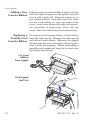
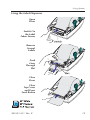
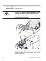
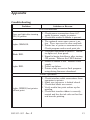
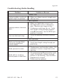
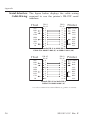
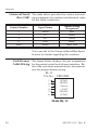
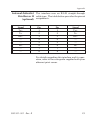
1
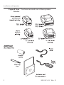
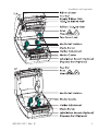
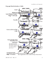
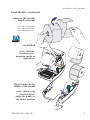
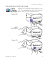
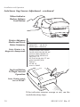
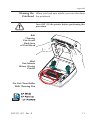
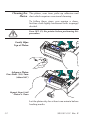
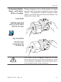
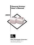
Thermal Printer
User’s Manual
2824
2844
3842
User’s Manual No. 980381-001 Rev. B
©2003 ZIH Corp.
ii
980381-001 Rev. B
FOREWORD
This manual provides installation and operation information for the 2824, 2844 and the 3842
series printers, manufactured by Zebra Technologies Corporation, Camarillo, California.
COPYRIGHT NOTICE
This document contains information proprietary to Zebra Technologies Corporation. This document and the information contained within is copyrighted by Zebra Technologies Corporation and
may not be duplicated in full or in part by any person without written approval from Zebra Technologies Corporation. While every effort has been made to keep the information contained within current and accurate as of the date of publication, no guarantee is given or implied that the document
is error-free or that it is accurate with regard to any specification. Zebra Technologies Corporation
reserves the right to make changes, for the purpose of product improvement, at any time.
TRADEMARKS
LP 2824, TLP 2824, LP 2844,TLP 2844 and TLP 3842 are service marks of Zebra Technologies
Corporation. Windows and MS-DOS are registered trademarks of Microsoft Corp. All other marks
are trademarks or registered trademarks of their respective holders.
LP 2824, TLP 2824, LP 2844, TLP 2844 and TLP 3842
Thermal Printers
European Council Directive
89/336/EEC
Compliance to Standards
EMC Directive
EN 55022-B 1998
RF Emissions control
EMC Directive
EN 55024 1998
Immunity to Electromagnetic Disturbances
92/31/EE
EMC Directive
EN 61000-3-2
Harmonic Emissions
92/31/EE
EMC Directive
EN 61000-3-3
Voltage Variation
CB Scheme
EN 60950 1991
A1, A2, A3, A4
Safety
FCC - DECLARATION OF CONFORMITY:
Models: LP 2824, TLP 2824, LP 2844, TLP 2844 and TLP 3842 conform to
the following specification: FCC Part 15, Subpart B, Section 15.107(a) and
Section 15.109(a) Class B digital device
Supplemental Information:
This device complies with Part 15 of the FCC Rules. Operation is subject to the following Two
Conditions: (1) This device may not cause harmful interference, and (2) this device must accept
any interference received, including interference that may cause undesired operation.
INDUSTRY CANADA NOTICE:
This device complies with Industry Canada ICS-003 class B requirements.
Cet equipement est conforme a l’ICS-003 classe B de la norm Industrielle Canadian
980381-001 Rev. B
iii
SHOCK HAZARD WARNING:
The printer and power supply should never be operated in a
location where either one can get wet. Personal injury could
result.
MEDIA AND RIBBON WARNING:
Always use high quality, approved labels, tags and ribbons. If
adhesive backed labels are used that DO NOT lay flat on the
backing liner, the exposed edges may stick to the label guides
and rollers inside the printer, causing the label to peel off from
the liner and jam the printer. Permanent damage to the print
head may result if a non-approved ribbon is used as it may be
wound incorrectly for the printer or contain chemicals
corrosive to the print head. Approved supplies can be ordered
from your dealer.
RELOADING HINT:
If labels or ribbon run out while printing, DO NOT turn the
power switch OFF (0) while reloading or data loss may result.
The printer automatically restarts after you load a new label or
ribbon roll.
STATIC DISCHARGE:
The discharge of electrostatic energy that accumulates on the
surface of the human body or other surfaces can damage or
destroy the print head or electronic components used in this
device. DO NOT TOUCH the print head or the electronic
components under the top cover.
THERMAL PRINTING:
The print head becomes hot while printing. To protect from
damaging the print head and risk of personal injury, avoid
touching the print head. Use only the cleaning pen to perform
maintenance.
iv
980381-001 Rev. B
TABLE OF CONTENTS
Installation and Operation
Unpack Your Printer . . . . . . . . . . . . . . . . . . . . 2
Installation . . . . . . . . . . . . . . . . . . . . . . . . . 4
Operation . . . . . . . . . . . . . . . . . . . . . . . . . 12
Using Options
Using Transfer Ribbon. . .
Using the Label Dispenser .
Using Fan-Fold Media. . .
Using the Media Cutter . .
Clearing the Media Cutter .
.
.
.
.
.
.
.
.
.
.
.
.
.
.
.
.
.
.
.
.
14
19
20
21
22
Appendix
Troubleshooting . . . . . . . . . . . . . . . . . . .
Serial Interface Cable Wiring . . . . . . . . . . . .
Parallel Interface Cable Wiring . . . . . . . . . . .
Universal Serial Bus (USB) . . . . . . . . . . . . .
Cash Drawer Cable Wiring . . . . . . . . . . . . .
Internal ZebraNet PrintServer II (optional). . . . . .
Alternative Serial Interface Input. . . . . . . . . . .
Cleaning the Printhead . . . . . . . . . . . . . . .
Cleaning the Platen . . . . . . . . . . . . . . . . .
Preparing Media, Paper, and Labels Before Loading
.
.
.
.
.
.
.
.
.
.
.
.
.
.
.
.
.
.
.
.
.
.
.
.
.
.
.
.
.
.
23
26
27
28
28
29
30
31
32
33
980381-001 Rev. B
.
.
.
.
.
.
.
.
.
.
.
.
.
.
.
.
.
.
.
.
.
.
.
.
.
.
.
.
.
.
.
.
.
.
.
.
.
.
.
.
.
.
.
.
.
.
.
.
.
.
.
.
.
.
.
.
.
.
.
.
v
vi
980381-001 Rev. B
1
Installation and Operation
This section provides information on the
installation and operation of the printer.
The printer is a low cost, desktop thermal
printer. The printer is specifically designed for
printing labels, tags or continuous receipts (with
or without bar codes) from any DOS™, Windows™or ASCII-based compatible host.
There are several models of printer. Many illustrations in this manual show the wide printer.
While there are some physical differences
among them, you can operate all printers using
the same procedures.
980381-001 Rev. B
1
Installation and Operation
Unpack Your You have received one of these printers:
Printer
2
980381-001 Rev. B
Installation and Operation
980381-001 Rev. B
3
Installation and Operation
Installation The following steps will guide you through the
installation of the printer and software.
Step
Attach Power Supply To The Printer
Power OFF
Check Voltage
Plug in
Power
Module
Plug in
Power
Cord
Plug Power Cord
into a Suitable
AC Outlet
See the SHOCK HAZARD WARNING on page
iv.
4
980381-001 Rev. B
Installation and Operation
Step
Attach Interface Cable
Serial
Parallel
Universal Serial Bus
(USB)
Internal ZebraNet
PrintServer II
(optional)
For details regarding
this interface and its
operation, refer to the
user guide supplied
with your ethernet
print server.
See Appendix A for cable wiring information.
980381-001 Rev. B
5
Installation and Operation
Step
Load Media
Open Cover
MOVIE
Open Guides
Adjust Holders
1.0 inch
2.5 cm
MOVIE
1.5 inch
3.8 cm
6
980381-001 Rev. B
Installation and Operation
Load Media - continued
Remove the outside
length of media
For more information
on media preparation,
refer to Appendix A.
MOVIE
Install Roll
Note: Find the
instructions for
preparing media in
Appendix A.
Close Guides to the
Width of the Media
Note: When using
linerfree labels,
adjust the guides to
the widest position
980381-001 Rev. B
7
Installation and Operation
Load Media - continued
Release Cover
Note: This step
applies to thermal
transfer printers
MOVIE
Close Cover
8
980381-001 Rev. B
Installation and Operation
Step
AutoSense Media Gap Sensing
Perform this procedure when loading a new
roll. If your printer has the label dispenser
option, turn OFF the label taken sensor.
MOVIE
Power OFF
Hold
Feed Button
Power ON
980381-001 Rev. B
9
Installation and Operation
AutoSense Gap Sensor Adjustment - continued
When Indicator
Flashes, Release
Feed Button
Printer Advances
Media and Prints
Status Summary
Note: Printer is in
diagnostic dump mode
UKQ1935
16 V3.21
Serial port : 96,N,8,1
Image buffer size:1032K
Fmem:000.0K,016.4K avl
Gmem:000K,0593K avl
Emem:000K,0593K avl
I8,0,001 rY
S2 D10 R016,000 ZT UN
q800 Q01225,026
Option:
04 08 13
now in DUMP
Tap Feed Button
To Begin Normal
Operation
Note: Printer prints
“out of DUMP”
e
l
4
0,
Imagem:00 00K,02 41K av
Fm em:0 0K,02
UN
ZT
Gm em:00 rY
00
Em ,001 016,0 5
I8,0 D10 R 29,02
S2 0 Q10
q80 tion:
Op 08 13 UMP
04
in D
now
If the indicator remains orange or red, see the
troubleshooting steps.
10
980381-001 Rev. B
Installation and Operation
Step
Install Software
Start your computer and follow the installation
instructions on the compact disc (CD).
980381-001 Rev. B
11
Installation and Operation
Operation The following information helps you get the
most from your printer.
Programming You must use programming to control many of
Commands the printer's functions. See the EPL2 programmer's manual for details. For example, the Q
command controls form length and gap.
Printer Driver The printer driver provides a convenient control
to improve print quality. For example, Print
density (darkness) is affected by the heat energy
(density setting) applied and by the print speed.
Changing both Print Speed and Density may be
required to achieve the desired results.
Thermal Printing: You must use the correct media for the type of
Direct or printing you require. When printing without a
Transfer? ribbon, you must use direct thermal media.
When using ribbon, you must use thermal transfer media. The printer's ribbon sensor detects
motion of the supply spindle.
Replacing Supplies When replacing media or ribbon, do not turn off
the printer or data loss occurs. The printer automatically resumes printing after you load new
supplies.
12
980381-001 Rev. B
Using Options
2
Using Options
This section provides information on the
printer's optional features:
• thermal transfer printing
• label dispenser
• fan-fold media
• media cutter
980381-001 Rev. B
13
Using Options
Using Transfer The TLP printer supports both direct thermal
Ribbon media (chemically treated to darken when
heated) and thermal transfer media (accepts
wax and/or resin transferred off a ribbon).
Step
Prepare Ribbon
Pull Adhesive
Strip Free
MOVIE
14
980381-001 Rev. B
Using Options
Step
Install Supply Roll
Thread
Ribbon
Through
Carriage
Press
onto Hub
Align Notches
onto Hub Spokes
980381-001 Rev. B
15
Using Options
Step
Install Take-Up Core
Press
onto Hub
Align Notches
onto Hub Spokes
16
980381-001 Rev. B
Using Options
Step
Tighten Ribbon
Attach Ribbon to
Take-Up Core
Notes:
Align ribbon so
that it will be taken
straight onto core.
Use the adhesive
strip on new rolls;
otherwise, use
tape.
Remove Slack
From Ribbon
When using ribbon, make sure you also use
thermal transfer media.
980381-001 Rev. B
17
Using Options
Adding a New If ribbon runs out in the middle of a print job, the
Transfer Ribbon indicator lights orange and the printer waits for
you to add a fresh roll. Keep the power on as
you change ribbon. Open the top cover, then
cut the used ribbon so you can remove the
cores. Load a new ribbon roll (refer to the previous procedure if necessary). Close the top
cover. Press the Feed button to restart printing.
Replacing a To remove used transfer ribbon, cut the ribbon
Partially Used from the take-up roll. Remove the take-up roll
Transfer Ribbon and discard used ribbon. Remove the supply
roll and tape the end of any fresh ribbon to prevent it from unwrapping. When reinstalling a
partially used supply roll, tape the cut end onto
the empty take-up roll.
Cut Used
Ribbon
from Supply
Push Supply
Roll Out
18
980381-001 Rev. B
Using Options
Using the Label Dispenser
Open
Door
Switch On
the Label
Taken Sensor
Remove
Several
Labels
Push
Liner
Through
Slot
Close
Door
Close
Top Cover
and Press
Feed Button
MOVIE
980381-001 Rev. B
19
Using Options
Using Fan-Fold Media
Insert
Media
Adjust Holders
to Width of Media
2844–Tighten Screw
(use a small
Phillips driver #1)
2824–Lock Guides in
Place
Adjust Guides
to Width of Media
20
980381-001 Rev. B
Using Options
Using the Printers that have a bezel with a motorized
Media Cutter blade can dispense one or more forms that are
then automatically cut from the media supply.
This option cuts through continuous paper from
rolls and liner between labels.
Use the OC command to activate the cutter and
the Q command to set the form length and gap
distance. See the EPL2 programmer's manual.
980381-001 Rev. B
21
Clearing the If the blade cuts through labels, adhesive can
Media Cutter jam the cutter.
Turn OFF (O) printer power and unplug the power
and interface cables before clearing the cutter.
Keep the cutter dry. Never use any solutions or
solvents to clean the blade.
After removing debris, plug in the power and
interface cables, turn on the printer, then test for
normal operation.
22
980381-001 Rev. B
Appendix
Troubleshooting
Problem
Solution or Reason
STATUS Indicator
Does not light after turning
ON ( ❙ ) printer.
1. Check power connections from A.C.
outlet to power supply to printer.
2. Check that media or ribbon is present.
Lights ORANGE.
1. The optional cover open sensor is active. Press top cover to close and lock.
2. Printer has a syntax or command error.
Check program and resend print job.
Blinks RED.
1. Firmware download in process. Indicator lights red, then green.
2. Signal to begin AutoSense after turning
ON printer. Release the FEED button.
Lights RED.
1. Media or ribbon is out. Reload a new
supply.
2. Power-up failure.
3. Printer ready to receive flash programming during firmware download.
Printer Operation
Lights GREEN, but printer
will not print.
980381-001 Rev. B
1. Check interface cable connections from
computer to printer.
2. Make sure top cover is locked closed.
3. Check that labels are correct.
4. Verify media has print surface up for
printing.
5. Check that transfer ribbon is correctly
routed and has the ink side out for thermal transfer printing.
23
Appendix
Problem
Solution or Reason
Printer Operation--continued
Printer appears to be
working (media is being fed
out), but nothing is printed.
1. Verify that the labels are the correct
type.
2. Check that the roll is loaded with the direct thermal side facing up.
3. Clean the print head with cleaning pen.
4. Ensure top cover is locked closed.
Printing is faded or poor
quality.
1. Clean the print head with cleaning pen.
2. Adjust print speed/darkness in software.
3. Check the media and verify that print
surface is facing up.
4. Check the correct combination thermal
transfer ribbon and media are in use.
Prints only partial label or
skips a label.
1. Perform AutoSense gap sensor
adjustment on page 9.
2. Label caught on print head.
3. Top cover is not properly latched.
4. Possible software problem. Check the
printer memory configuration. Refer to
the EPL2 Programming manual.
Printing stops and STATUS
indicator lights ORANGE or
RED.
1. Perform AutoSense gap sensor adjustment on page 9.
2. Possible problem with label stock. Use
only approved labels and tags.
3. Possible label jam.
4. Insufficient memory for label size. Check
the printer memory configuration.
5. Possible software problem. Refer to the
EPL2 Programming manual.
24
980381-001 Rev. B
Appendix
Troubleshooting Media Handling
Problem
Solution or Reason
Ribbon Path
Evident wrinkles result in di- 1. Make sure ribbon mounts straight onto
agonal stripes on printout.
take-up core.
Label Dispenser
Printing continues between
labels.
1. Make sure label-taken sensor is on.
2. The label-taken sensor is blocked or
dirty. Remove any scraps or dust.
3. Continuous media may be set. Verify
form length setting through programming Q command. See the EPL2 programmer's manual.
Print one label and stops.
1. Verify the quantity has been correctly
set.
Cutter Operation
Blade cuts through labels
instead of cutting liner
between labels.
1. Verify form length setting through programming.
Media jammed in cutter.
1. Unplug power and interface cables. Use
tweezers to remove scraps from cutter
opening.
Media fails to cut direct
thermal paper or label liner.
1. Use programming C command to cycle
cutter several times without media to
perform a self-cleaning. See the EPL2
programmer's manual.
2. Cutter must be replaced.
980381-001 Rev. B
25
Appendix
Serial Interface The figure below displays the cable wiring
Cable Wiring required to use the printer's RS-232 serial
interface.
Host
N/C
RxD
TxD
DTR
GND
DSR
RTS
CTS
RI
DB-9
Pin #
1
2
3
4
5
6
7
8
9
DB-9
Pin #
1
2
3
4
5
6
7
8
9
Printer
+5 Volts*
TxD
RxD
CTS
GND
RDY
N/C
RDY
N/C
Female DB-9 to Male DB-9
Cable P/N 300017-006 (6') or 300017-010 (10')
Host
N/C
RxD
TxD
DTR
GND
DSR
RTS
CTS
RI
DB-25
Pin #
8
3
2
20
7
6
4
5
22
DB-9
Pin #
1
2
3
4
5
6
7
8
9
Printer
+5 Volts*
TxD
RxD
N/C
GND
RDY
N/C
RDY
N/C
Female DB-25 to Male DB-9
Cable P/N 300018-006 (6')
*+5 volts at 150 mA for external device (e.g. KDU or scanner)
26
980381-001 Rev. B
Appendix
Parallel Interface The figure below displays the cable wiring
Cable Wiring required to use the printer's Centronics parallel
interface.
HOST
DB-25
Pin No.
STROBE~
DATA 0
DATA 1
DATA 2
DATA 3
DATA 4
DATA 5
DATA 6
DATA 7
ACK~
BUSY
PAPER ERR.
SELECT
AUTOFD~
ERROR~
N/A
N/A
N/A
SIG. GND
SIG. GND
SIG. GND
SIG. GND
SIG. GND
SIG. GND
SIG. GND
1
2
3
4
5
6
7
8
9
10
11
12
13
14
15
16
17
18
19
20
21
22
23
24
25
Centronics
Pin No. PRINTER
1
2
3
4
5
6
7
8
9
10
11
12
13
14
15
16
17
18
19
20
21
22
23
24
25
26
27
28
29
30
31
32
33
34
35
36
STROBE~
DATA 0
DATA 1
DATA 2
DATA 3
DATA 4
DATA 5
DATA 6
DATA 7
ACK~
BUSY
PAPER ERR.
SELECT
AUTOFD~
n/c
SIG. GND
CHAS GND
+5V
SIG. GND
SIG. GND
SIG. GND
SIG. GND
SIG. GND
SIG. GND
SIG. GND
SIG. GND
SIG. GND
SIG. GND
SIG. GND
SIG. GND
n/c
ERROR~
SIG. GND
n/c
n/c
SELECTIN~
Male DB-25 to Male Centronics (Cable)
+5 volts at 300 mA for external device (e.g. KDU or scanner)
980381-001 Rev. B
27
Appendix
Universal Serial The table below provides the contact terminatBus (USB) ing assignments by number and electrical value
for the cable connectors.
Contact Number
Signal Name
Typical Wiring
Assignment
1
VBUS
Red
2
D-
White
3
D+
Green
4
GND
Black
Shell
Shield
Drain Wire
You can refer to the Universal Serial Bus Specification for details regarding this interface.
Cash Drawer The figure below displays the pin assignments
Cable Wiring for the printer's retail cash drawer interface. Refer to the cash draw manufacturer's documentation for proper drawer wiring.
RJ-11
Pin No. PRINTER
1
2
3
4
5
6
SGND
/SDRV1
/Sense
+24V*
/SDRV2
LGND
Male RJ-11
28
980381-001 Rev. B
Appendix
Internal ZebraNet This interface uses an RJ-45 straight-through
PrintServer II cable type. The table below provides the pinout
(optional) assignments.
Signal
Pin
Pin
Signal
Tx+
1
1
Tx+
Tx-
2
2
Tx-
Rx+
3
3
Rx+
---
4
4
---
---
5
5
---
Rx-
6
6
Rx-
---
7
7
---
---
8
8
---
For details regarding this interface and its operation, refer to the user guide supplied with your
ethernet print server.
980381-001 Rev. B
29
Alternative Serial The pinout of the RJ-11 interface connector is
Interface Input listed below.
Host
DCD
RxD
TxD
DTR
GND
DSR
RTS
CTS
RI
DB-9
Pin #
1
2
3
4
5
6
7
8
9
RJ-11
Pin #
1
2
3
4
5
6
Printer
RxD
TxD
BUSY
GND
+5V*
RTS
Female DB-9 to RJ-11
*+5 volts @ 160 mA max.
Pin 4
Pin 5
Pin 6
Pin 3
Pin 2
Pin 1
Front View of RJ-11
Modular Connector
Note that looking into the printer’s connector
with the key notch pointing down, pins are
numbered from left to right.
30
980381-001 Rev. B
Appendix
Cleaning the When you load new media, you can also clean
Printhead the printhead.
Turn OFF (O) the printer before performing this
procedure.
Rub
Cleaning
Pen Across
Dark Area
of Print Head
Wait
One Minute
Before Closing
Printer
Do Not Clean Roller
With Cleaning Pen
MOVIE
980381-001 Rev. B
31
Cleaning the The platen, over time, picks up adhesive and
Platen dust which requires occasional cleaning.
To follow these steps, you require a clean,
lint-free cloth lightly moistened with isopropyl
alcohol.
Turn OFF (O) the printer before performing this
procedure.
Gently Wipe
Top of Platen
Advance Platen
One-Sixth (1/6) Turn
(about 60°)
Repeat Steps Until
Platen is Clean
Let the platen dry for at least one minute before
loading media.
32
980381-001 Rev. B
Appendix
Preparing Media, During shipment, the outside length of media
Paper, and Labels may become dirty when handled or dusty when
Before Loading stored. A preparation before loading media
makes sure both the print head and platen stay
cleaner for more time.
Label Rolls
Find the tape and
pull off both labels
held by the tape
MOVIE
Tag Stock Rolls
Find the tape
and detach the
bottom tag
You must avoid dragging adhesive or dirty
media between the print head and platen. Such
an occurrence damages the print head and is
not covered under your warranty.
980381-001 Rev. B
33
980381- 001B