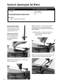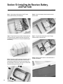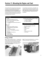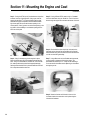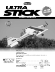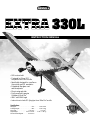
1
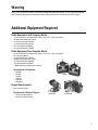
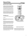
TM
WE GET PEOPLE FLYING
INSTRUCTION MANUAL
• 90% custom built
• Designed by 7-time TOC
competitor Mike McConville
• Specifically designed for excellence
in precision and 3D aerobatics
• Prepainted fiberglass cowl
and wheelpants
• Plug-in wing and stab
• Precovered with genuine
Goldberg UltraCote®
• IMAC and IMAA legal
• Instructions include 3D flying tips from Mike McConville
Specifications
Wingspan: . . . . . . . . . . . . . . . . . . . . . . . 97 in
Fuselage Length: . . . . . . . . . . . . . . . . . 88 in
Wing Area: . . . . . . . . . . . . . . . . . 1,750 sq in
Flight Weight: . . . . . . . . . . . 23.5 to 26.5 lb
Recommended Engines: . . . . . . 60 to 80 cc
. . . . . . 2,463.8 mm
. . . . . . 2,235.2 mm
. . . . . . . . 112.9 dm2
. . . 9.98–11.80 kg
Table of Contents
Introduction ..................................................................................................................................................................................... 2
Warning
..................................................................................................................................................................................... 3
Additional Equipment Required ............................................................................................................................................................ 3
Other Items Needed (not included in the kit) ......................................................................................................................................... 4
Tools and Supplies Needed (not included in the kit) ............................................................................................................................. 4
Contents of Kit ......................................................................................................................................................................................5
Section 1. Installing the Aileron Servos ............................................................................................................................................. 6
Section 2. Installing the Aileron Control Horns .................................................................................................................................. 7
Section 3. Hinging and Sealing the Control Surfaces ......................................................................................................................... 9
Section 4. Installing the Linkages .................................................................................................................................................... 13
Section 5. Installing the Rudder and Elevator Servos ....................................................................................................................... 14
Section 6. Installing the Elevator, Control Horns, and Linkages ....................................................................................................... 16
Section 7. Installing the Rudder, Control Horns, and Linkages ........................................................................................................ 19
Section 8. Installing the Landing Gear ............................................................................................................................................. 21
Section 9. Attaching the Tail Wheel .................................................................................................................................................. 24
Section 10. Installing the Receiver, Battery, and Fuel Tank ................................................................................................................. 25
Section 11. Mounting the Engine and Cowl ....................................................................................................................................... 27
Section 12. Hatch Assembly .............................................................................................................................................................. 30
Section 13. Balancing the Model ....................................................................................................................................................... 31
Section 14. Radio Setup ..................................................................................................................................................................... 32
Section 15. Control Throws ............................................................................................................................................................... 32
Preflight at the Field ........................................................................................................................................................................... 32
Setup and Flight Tips by Mike McConville ......................................................................................................................................... 33
AMA Safety Code ............................................................................................................................................................................... 39
Introduction
Thank you for your purchase of Hangar 9’s Extra 330L. Because the size and weight create a higher degree for potential danger, an
added measure of care and responsibility is needed when building and flying giant-scale models. If this is your first giant-scale
aerobatic aircraft, it’s important that you carefully follow the instructions, especially those regarding hinging (pages 9–10), sealing the
hinge gaps (pages 11–12), and the section on flying (pages 33).
Like all giant-scale aerobatic aircraft, the Extra requires powerful, heavy-duty servos. Servos greatly effect the flight performance, feel,
and response of the model. To get the most out of your Extra, it’s important to use accurate, powerful servos with a minimum of 80 oz/in
of torque. In the prototype models we used JR 8101s and JR 8411s with excellent results. A less powerful servo can lead to a crash.
The Extra 330L does not include hardware. Many experienced giant-scale pilots have specific hardware preferences and can
individually choose the components that they prefer. Hangar 9 offers an optional hardware package (page 5) part (#HAN1220, JR/
#HAN1221, FUT) that includes the hardware that our staff regularly uses and recommends.
Throughout the manual, the above hardware will be used during the assembly process. If using another type/brand of hardware, it’s
your responsibility to be sure that it’s strong enough for this application and properly installed.
2
If you encounter difficulty in any construction sequence, please contact one of our technicians. We stand ready to provide any
assistance we can concerning the construction of your Extra 330L. Contact us at:
Horizon Hobby, Inc.
4105 Fieldstone Road, Champaign, IL 61822
(877) 504-0233 www.horizonhobby.com
Warning
An R/C aircraft is not a toy! If misused, it can cause serious bodily harm and damage to property. Fly only in open areas, preferably
AMA (Academy of Model Aeronautics) approved flying sites, following all instructions included with your radio and engine.
Additional Equipment Required
Radio Equipment with Computer Radio
•
•
•
•
•
•
(7) Servos with 80 oz/in of torque minimum (JR8101, 4721, 2721, or 8411 or equivalent)
1000mAh receiver battery pack or larger
(4) 24" Servo Extensions (JRPA102)
(1) 18" Servo Extensions (JRPA101)
(2) 6" Servo Extensions (JRPA095)
(2) 12" Servo Extensions (JRPA099)
Radio Equipment Non-Computer Radio
•
•
•
•
•
•
(7) Servos with 80 oz/in of torque minimum (JR8101, 4721, 2721, or 8411 or equivalent)
(3) Y-Harnesses (JRP133)
(4) 18" Servo Extensions (JRPA101)
1000mAh receiver battery pack or larger
(2) 12" Servo Extensions (JRPA099)
(2) 6" Servo Extensions (JRPA095)
Note: Requires one reversed servo for elevator
Recommended JR Systems:
•
•
•
•
•
•
JR 400EX
JR 421EX
JR XP652
JR XP783
JR XP8103
JR PCM10X
JR 8103
Engine Requirements
• 60-80 cc Gasoline Engine
Recommended Gasoline Engines:
Zenoah G-62
Zenoah GT-80
• Zenoah G-62 Gasoline Engine
• Zenoah GT-80 Gasoline Engine
3
Other Items Needed (not included in the kit)
Zenoah Gas Start-up Package (ZEN20002) Includes:
•
•
•
•
•
•
•
•
Kill Switch (ZEN20000)
Oil (2 Cycle) (ZEN20001
Fuel Dot (HAN115)
Fuel Filter (HAN143)
Mix Cup (HAN3101)
Gas Stopper (DUB400)
3' Fuel Line (DUB799)
Line keeper (DUB677))
Tools and Adhesives Needed (not included in the kit)
Tools
Adhesives
•
•
•
•
•
•
•
•
•
•
•
•
•
•
•
•
•
•
•
•
•
•
•
•
•
•
•
Thick CA (cyanoacrylate) glue
CA remover/debonder
30-minute epoxy
5-minute epoxy
Silicon glue
Canopy glue
Blue Locktite®
Electrical tape
Masking tape
•
•
•
•
Rubbing alcohol
Felt-tipped pen/pencil
White UltraCote® (GBG870)
Pearl Blue UltraCote® (GBG845)
Drill
Drill bits: 1/16", 1/8", 5/32", 1/4", 3/8", 1/2", 5/16"
Medium Phillips screwdriver
Small straight screwdriver
Needle-nose pliers
Hobby knife with #11 blade
Mixing stick
Straight edge
Jig saw
Soldering iron
Measuring device (e.g., ruler, tape measure)
Scissors
Moto-tool with cut-off wheel
8-32 Tap (DUB363)
Sealing iron
Glue syringe or tooth pick
5/32" and 1/8" Hex wrench
Adjustable wrench
Addition Needed Items
• 4" spinner
• Propeller
(Refer to recommendations listed in your engine’s
operating instructions.)
• 2' gas compatible tubing
• Cup engine mount B+B 6202 (G-62 only)
• Coarse sandpaper
• Radio packing foam
• Antenna tube
• 1/8" light plywood
• (4) 1/4"-20 x 1/4" Socket head screws (G-62 only)
• 1/3 Scale Pilot (HAN8265)
• (2) Small cable ties
• Paper towels
4
Contents of Kit
Note: Photos of products may vary slightly from the contents in the box.
Replacement Parts
•
•
•
•
•
•
•
Fuselage (HAN1201)
Right Wing Panel with Aileron (HAN1202)
Left Wing Panel with Aileron (HAN1203)
Right Horizontal Stabilizer and Elevator (HAN1204)
Left Horizontal Stabilizer and Elevator (HAN1205)
Landing Gear Fairing (HAN1216)
Rudder (HAN1208)
•
•
•
•
•
•
•
Wing Tube (HAN1206)
Stabilizer Tubes (2) (HAN1207)
Canopy (HAN1209)
Canopy Hatch (HAN1210)
Fiberglass Painted Cowl (HAN1211)
Wheel Pants (HAN1212)
Landing Gear (HAN1213)
Included in the optional Hangar 9 1/3 Scale Hardware Package (HAN1220,JR/HAN1221, Futaba)
•
•
•
•
•
•
•
•
31/2" Wheels (2) (DUB350L)
41/2" 4-40 Threaded Pro-Links (4) (HAN3556)
5" 4-40 Threaded Pro-Links (2) (HAN3557)
32 oz Fuel Tank (DUB690)
Tail Wheel Assembly with Hardware (OHI130)
4-40 Ball Links (7) (ROC87)
8-32 Swivel Control Horns (6) (ROC01B)
4-40 Rod, Threaded one end (6) (DUB802)
•
•
•
•
•
•
•
•
3/16" Main Axles (DUB249)
Super Hinge Points (24) (ROB309)
4-40 1/2 3D Arm (11/4") JR (2) (HAN3578)
4-40 1/2 HD Arm (1") JR (4) (HAN3574)
4-40 1/2 3D Arm (11/4") Futaba (2) (HAN3579)
4-40 1/2 HD Arm (1") Futaba (4) (HAN3575)
4-40 Solder Link (2) (DUB305)
3/16" Wheel Collars (2) (DUB141)
5
Section 1: Installing the Aileron Servos
Parts Needed
Tools and Adhesives Needed
• Wings w/ailerons attached (taped in place)
•
•
•
•
Not Included
• (2) servos w/mounting hardware
(80 oz/in minimum torque)
• (2) 12" servo extensions
Phillips screwdriver
Drill with 1/16" drill bit
Electrical tape
Blue Locktite®
Included in Optional Hangar 9 Hardware Package
(HAN1220 JR or HAN1221 Futaba)
• (2) 1" Servo Arms (HAN3574 JR or HAN3575 Futaba)
The ailerons require a minimum of 80 oz/in of servo torque. In
the prototype Extras, we used JR8101 and JR8411 servos.
JR’s 8411s offer a crisp response — the ultimate servo choice.
Step 4. Using the screws included with the servo, fasten the
servo in place. You may find it helpful to drill a 1/16" pilot hole
before installing the screws.
JR8101 Ultra Precision Wide Bearing
Torque: 90.4 oz/in
Speed: .23 sec/60°
Weight: 1.5 oz
Size: .73" x 1.52" x 1.32"
Motor: Coreless
Ball Bearing: Dual
JR8411 Digital Ultra Torque
Torque: 155 oz/[email protected] Speed: .18 sec/60°
Weight: 2.03 oz
Size: .73" x 1.52" x 1.32"
Motor: Coreless
Ball Bearing: Dual
Step 1. Install the servo hardware (grommets and eyelets)
included with the servo.
Step 2. Plug a 12" servo extension onto each servo. Tie a knot
at the connector as shown, then wrap with electrical tape to
prevent the servo connectors from pulling apart.
ge
Ed
g
n
i
ail
Tr
Step 5. Remove the stock arms and replace with heavy-duty
1" arms (HAN3574 JR or HAN3575) to give the needed control
throws and to handle the increased loads of the large surfaces.
The arms need to face outward toward the wing tips as shown in
the photo. Be sure to use a drop of Blue Locktite to secure the
servo arm screws if using metal-geared servos.
Tip
ng
Wi
Step 3. Insert the servo into the aileron cutout in the bottom of
the wing as shown. Be sure the output shaft is oriented closest to
the trailing edge of the wing. Allow the servo lead to exit the root
of the wing. Refer to the photo in Step 4.
6
Section 2: Installing the Aileron Control Horns
Parts Needed
Tools and Adhesives Needed
• Wings with ailerons and servos
•
•
•
•
•
•
•
Included in Optional Hangar 9 Hardware Package
• (2) Control Horns (Rocket City 8-32 Swivel Control
Horn #ROC01B)
Step 1. Using a straight edge held in alignment (90°) with the
servo arm and with the hinge line as shown, mark the aileron with
a pen where the straight edge intersects the aileron hinge bevel.
12" or longer ruler
Drill w/ 5/32" drill bit
8-32 Tap (DUB363)
30-minute epoxy
Pen
Rubbing alcohol
Paper towels
Step 3. Untape the ailerons from the wing. Use rubbing alcohol
to remove any tape residue. Notice that the hinge pockets are
already cut into place.
s
cket
e Po
Hing
Step 2. Measure exactly 1/4" rearward from the mark above
parallel to the hinge line and make another mark using a pen.
This will be the position for the control horn.
Step 4. Using a 5/32" drill bit and hand drill, carefully drill a
5/32" hole through the aileron at the marked position. [Drill
perpendicular (90°) to the aileron cross section rather than the
ailerons surface.] Be especially careful when penetrating through
the bottom surface of the aileron as it’s easy to split out the wood
and rip the covering. Placing a wooden block under the aileron
and drilling slowly will prevent these problems. If you choose to
use the counter sink screws included in the Hangar 9 Hardware
Package, counter sink the top of the aileron to allow the screws
to fit flush.
Note: A hardwood block (hardpoint) is located below the
sheeting; you will be drilling through this.
90°
7
Section 2: Installing the Aileron Control Horns
CONTINUED
Step 5. Using an 8-32 tap, tap the hole that you just drilled in
the aileron.
Step 6. Mix a small amount of 30-minute epoxy and lightly coat
the inside of the tapped hole and the 8-32 x 2" Rocket City screw.
From the top of the aileron, screw the 8-32 x 2" into the tapped
hole and securely tighten. Wipe away any excess epoxy with
rubbing alcohol and a paper towel. Screw the A-nut in place as
shown. Allow the epoxy to fully cure.
8
Step 7. Screw the molded swivel link onto the 8-32 screw until
the distance from the aileron surface to the bottom of the link
is 5/8".
Step 8. Install the control horn in the opposite aileron using the
same method.
Section 3: Hinging and Sealing the Control Surfaces
Parts Needed
Tools and Adhesives Needed
• Wings with ailerons
•
•
•
•
•
•
•
•
•
Included in optional Hangar 9 Hardware Package
• (24) Robart Super Hinge Points #ROB309
Not included
• White UltraCote® (GBG870)
• Pearl Blue UltraCote® (GBG845)
Properly hinging the control surfaces on giant-scale models is
vitally important! Poorly installed hinges affect the model’s
precision and control response and can also be dangerous. Each
and every hinge needs to be securely bonded in place in both the
flying surface and the control surface. The hinge pivot points
need to be exactly parallel to each other and precisely located on
the center of the hinge line. We regularly use Robart Super Hinge
Points in all giant-scale aircraft. They are easy to install, very
strong, and offer smooth friction-free control. The Hangar 9
Extra 330L control surfaces are predrilled to use Robart’s Super
Hinge Points.
Sealing iron
Sharp #11 hobby knife
Ruler, 36"
Glue Syringe (DLR910) (or toothpick)
Coarse sandpaper
Pen
30-minute epoxy
Rubbing alcohol
Paper towels
flush and parallel with the trailing edge. Continue installing
hinges in the trailing edge of the wing. The control surfaces
(ailerons) will be installed after the epoxy is fully cured.
Step 1. Sand each end of the hinge point hinge using coarse
sandpaper. This will improve the bond of the epoxy to the hinge.
Note: Be sure that the hinge pivot pins are parallel and
flush to the trailing edge. It’s important to frequently
mix a fresh batch of 30-minute epoxy in order to
achieve good glue joint penetration. If you notice the
epoxy becoming thicker, then mix a new batch!
Step 2. Mix 1 ounce of 30-minute epoxy. Using a glue syringe
or toothpick, place a sufficient amount of 30-minute epoxy into
one of the hinge pockets on the wings trailing edge. Install one
of the hinge points until the hinge pin center is flush with the
trailing edge of the wing. Some epoxy should ooze out of the
pocket as the hinge is installed. If not, remove the hinge and
apply more epoxy. After gluing a few hinges, you’ll get the hang
of just how much epoxy is needed. Wipe away any excess epoxy
with rubbing alcohol. Recheck that the center of the hinge pin is
9
Section 3: Hinging and Sealing the Control Surfaces
CONTINUED
Step 3. Allow the epoxy to fully cure for at least 6 hours. When
cured, work each hinge throughout its full motion several times
using your hands. This will break free any epoxy that may have
found its way into the hinge joint. Move the hinge throughout its
full travel until no resistance is felt. This may take as many as
40 or 50 times.
Step 6. Double-check the hinge gap and allow the epoxy to
fully cure for at least 6 hours. Now is a good time to epoxy the
hinges on the other aileron half using the same techniques.
Step 4. Mix 1 ounce of 30-minute epoxy. Using a syringe or
toothpick, place a sufficient amount of epoxy in each of the hinge
pockets in one aileron half.
Step 7. When fully cured, move each control surface
throughout its travel range several times to break away any epoxy
in the hinge. Be sure to deflect the surface fully.
Step 5. Carefully install the aileron on the wing, making sure
the hinges are inserted in their respective hinge pockets. Press
the aileron and wing together such that less than a 1/64" hinge
line gap exists between the aileron and wing. The bevels should
virtually touch. Using a paper towel and rubbing alcohol, wipe
away any visible epoxy around the hinges.
10
Section 3: Hinging and Sealing the Control Surfaces
CONTINUED
Sealing the Hinge Gaps
It’s imperative that the aileron and elevator hinge lines be sealed
airtight to prevent flutter. Sealing the hinge line has several
advantages. A sealed hinge line gives a greater control response
for a given control deflection. It also offers more precise,
consistent control response and makes trimming easier.
Sealing the aileron and elevator hinge line is
mandatory. Failure to do so may cause control surface
flutter, resulting in a crash.
Step 3. Using a sharp #11 blade and a straight edge, carefully
cut through both layers of UltraCote® covering at the 1/2" point
marked in Step 2.
Step 1. Cut a piece of Pearl Blue UltraCote® (not included)
for sealing the ailerons to approximately 3" x 42". Fold the
UltraCote® down the center with the adhesive side to the outside
making a sharp crease at the fold.
Step 4. Mark and cut the folded covering to an overall length
of 40". This piece will be inserted and ironed down into the hinge
bevel on the bottom of the aileron.
Step 2. Using a ruler, measure 1/2" from the folded crease and
mark two places with a pen.
11
Section 3: Hinging and Sealing the Control Surfaces
CONTINUED
Sealing the Hinge Gaps (CONTINUED)
Step 5. Remove the backing from the UltraCote®. Place the
folded crease side into the center of the hinge line on the bottom
of the wing. Using a straight edge as shown, hold one side of the
covering in place while ironing down the opposite side with a
sealing iron. We recommend setting the iron temperature to
320° for this operation.
12
Step 6. Fully deflect the aileron in the up position. Place the
straight edge over the hinge line covering that you just ironed
down in Step 5 with the edge of the straight edge placed firmly at
the bottom of the hinge line as shown. Iron down this side of the
covering, making sure the aileron is fully deflected.
Section 4: Installing the Aileron Linkages
Parts Needed
Tools and Adhesives Needed
• Wings with ailerons attached
• Small screwdriver
• Blue Locktite®
Included in Optional Hangar 9 Hardware Kit
• (2) 41/2" 4-40 Pro-Links (HAN3556)
• (2) 4-40 Ball Links (ROC87)
Step 1. Screw a 4-40 ball link 5 to 6 turns onto a 41/2" long
4-40 linkage. Screw the opposite end of the linkage into the
swivel control horn that was installed in Step 2 five to six turns.
Adjust the linkage length until the hole in the ball link aligns with
the outer hole in the servo arm when the aileron is neutral and
the servo arm is centered.
Step 2. Using the 4-40 screws (don’t substitute a standard
screw) and nuts included in the Rocket City package, attach the
ball link to the outer hole in the arm from the bottom side as
shown. The sequence is screw, ball link, servo arm, and nut.
Don’t forget to use Blue Locktite. The tapered standoff is
not used.
Note: Hangar 9 Titanium Pro-Links feature right-hand
threads on one end and left- hand threads on the
other, allowing for easy, accurate adjustment without
disconnecting the linkages. Consistently putting the
right-hand threads toward the servo arms on all
servos will prevent you from getting confused as to
which way to turn the linkage to lengthen or shorten
the link. Hangar 9 also offers a Pro-Link Wrench
(HAN3558) to make adjustments easier.
13
Section 5: Installing the Rudder and Elevator Servos
Parts Needed
• Fuselage
Not included
• (4) Servos (a minimum of 80 in/oz of torque)
w/mounting hardware
• (2) Small cable ties
Using a computer radio
• (4) 24" Servo Extensions (JRPA102)
Using a non-computer radio
• (3) Y-harnesses (JRPA133)
• (4) 18" Servo Extensions (JRPA099)
See “Radio Setup” section for more details on page 32
Included in optional Hangar 9 Hardware Kit
• (2) 1" Heavy-Duty Servo Arms for Elevator
(HAN 3574 JR or HAN3575 Futaba)
• (2) 11/4" Heavy-Duty Servo Arms for Rudder
(HAN3578 JR or HAN3579 Futaba)
• (4) 41/2" 4-40 Linkages (HAN3556)
• (4) 4-40 Ball Links (ROC87)
• (2) Swivel Control Horns (ROC01B)
Tools and Adhesives Needed
• Phillips screwdriver
• Small straight screwdriver
Note: If using a non-computer radio, one of the
servos used for elevator must be a reverseddirection servo.
The rudder and elevators require a minimum of 80 in/oz of servo
torque. In the prototype Extras we used JR8101s and JR8411
servos with excellent results. Using servos with less torque
could cause a crash.
Computer Radio
Step 1. If using a 7-channel or greater computer radio with
mixing (highly recommended), install four 24" servo extensions,
one on each servo. Tie a knot at each connector and tape to
prevent inadvertent disconnection. Also install the servo
hardware (grommets and eyelets) at this time.
14
Non-Computer Radio
Step 1. If using a non-computer radio, install four 18" servo
extensions, one on each servo. Tape and tie a knot at each
connector to prevent inadvertent disconnection. Install one side
only of the two Y-harnesses to two of the servos, also tying knots
to prevent disconnection. The other two servos will be hooked up
to the Y-harness when installed in the airplane. One elevator
servo will need to be a reversed-direction servo.
Section 5: Installing the Rudder and Elevator Servos
CONTINUED
Non-Computer Radio (CONTINUED)
Step 2. Install the servos in the fuselage tail section with the
output shaft to the rear as shown in the photo. If using a noncomputer radio, be sure to install one of the servos with the
Y-harness attached in the top opening (elevator) and the other
servo with the Y-harness attached in the bottom opening
(rudder). Install the other servos in the opposite side of the
fuselage being sure to connect the servo to the other open
connector of the respective Y-harnesses. Don’t forget to tape and
knot the connectors. One of the elevator servos must be a
reversed servo.
Step 3. Using the screws included with the servos, fasten the
servos in place. You may find it helpful to drill a 1/16" pilot hole
before installing the screws.
15
Section 6: Installing the Elevator, Control Horns,
and Linkages
Parts Needed
Tools and Adhesives Needed
•
•
•
•
•
•
•
•
•
•
•
Stabilizers w/elevators
(2) 4-40 x 3/8" screws
(2) tail tubes
(2) #4 split washers
Not Included
• White UltraCote® (GBG870)
• Sealing iron
• #11 hobby knife
Drill with 5/32" drill bit
8-32 Tap (DUB363)
30-minute epoxy
Rubbing alcohol
Paper towels
Ruler
5/32" Hex wrench
Included in Optional Hangar 9 Hardware Package
• Robart Hinge Points (ROB309)
• Rocket City 8-32 Swivel Control Horn (ROC01B)
• (2) Control horns
• (2) 4-40 Ball Links (ROC87)
• (2) 41/2" 4-40 Pro-Links (HAN3556)
The technique for installing the control horns in the elevators is
similar to the aileron control horn installation.
Step 1. To properly locate the position of the control horn on
the bottom of the elevator, measure inward 1" from the root and
rearward 1/4" from the top of the bevel. Mark this position on
both elevators.
1/4"
1"
Step 2. Using a 5/32" drill bit and hand drill, carefully drill a
5/32" hole through the elevators at the above marked position. It’s
important to drill 90° to the elevator’s centerline to the elevator’s
surface. Be especially careful when penetrating through the
bottom surface of the elevator as it’s easy to split out the wood
and rip the covering. Placing a wooden block under the elevator
and drilling slowly will prevent these problems. If you choose to
use the counter sink screws included, counter sink the top of the
elevator to allow the screws to fit flush.
16
Step 3. Using an 8-32 tap, thread the holes that you just drilled
in the elevators.
Section 6: Installing the Elevator, Control Horns,
and Linkages
CONTINUED
Step 4. Mix a small amount of 30-minute epoxy and lightly coat
the inside of the threaded holes and the 8-32 x 2" Rocket City
screw. From the top of the elevator, thread the 8-32 screws into
the tapped holes and tighten. Wipe away any excess epoxy with
rubbing alcohol and paper towels.
Step 6. Glue the elevator hinges in place using the same
techniques used to hinge the ailerons. After hinging the elevator,
use the same technique to seal the elevator’s hinge gaps. Use
White UltraCote® for the bottom of the elevator. You can
substitute Clear UltraCote® if White is not available.
Step 7. Notice that the longer of the two tail tubes has a hole at
each end and that a hole is located near the center of the stab on
the top. It may be covered with UltraCote®. If so, use a #11 knife
blade to remove the covering over the hole. A 4-40 x 3/8" socket
head screw and split washer are threaded through the hole in the
each half of the stabilizer and into the tail tube. This securely
fastens the stab to the fuselage.
Step 5. Screw the molded swivel link onto the 8-32 screw until
the distance from the elevator surface to the bottom of the link is
5/8". Repeat this for the other elevator.
Step 8. Insert the longer of the two tubes into the rear hole in
the stabilizer root. Carefully align the hole in the tube with the
hole in the stab. Thread the 4-40 socket head screw and split
washer into the hole securing the tube to the stab.
17
Section 6: Installing the Elevator, Control Horns,
and Linkages
CONTINUED
Step 9. Insert the shorter of the two tail tubes into the forward
hole in the rear of the fuselage. Insert the stabilizer with tube in
the rear hole. Carefully slide the stab onto the tube until it
touches the side of the fuselage. This may be a tight fit.
Step 10. Install the other stabilizer onto the tube on the other
side of the fuselage. Carefully slide the stab onto the tubes until
it contacts the fuselage. When both stabs are touching the
fuselage, thread the other 4-40 socket head screw and split
washer into the top of the other stab to secure them in place.
Step 11. Remove the stock servo arms from the elevator servos
and replace them with heavy-duty 1" arms. The arms need to
face down as shown below. Be sure to use a drop of Blue
Locktite® on the servo arm screw if using metal geared servos.
Step 12. Screw a 4-40 ball link 5 to 6 turns onto a 4 1/2" long
4-40 linkage. Screw the opposite end of the linkage into the
swivel control horn on the elevator. Adjust the linkage length until
the hole in the ball link lines up with the outer hole in the servo
arm when the elevator is neutral and the servo arm is centered.
Note: Frequently check that these screws remain tight.
Step 13. Using the 4-40 screws and nuts included in the Rocket
City package, attach the ball link to the outer hole in the arm. The
correct sequence is 4-40 screw, ball link, servo arm, and 4-40
nut. (Don’t use the spacer/ standoff.) Be sure to use Blue Locktite®.
18
Section 7: Installing the Rudder, Control Horns,
and Linkages
Parts Needed
Tools and Adhesives Needed
• Rudder
• Fuselage
•
•
•
•
•
•
•
•
Not Included
• (2) Control Horns (ROC01B)
• (2) 4-40 Ball Links (ROC87)
• (2) 5" 4-40 Pro-Links (HAN3557)
Step 1. Mark the position for the rudder control horn with a
pen. The correct location is 3/4" up from the bottom of the rudder
and 1/4" rearward from the edge of the rudder bevel.
Drill with 5/32" drill bit
Phillips screwdriver
Straight screwdriver
8-32 Tap (DUB363)
30-minute epoxy
Rubbing alcohol
Paper towels
Ruler
Step 3. Using an 8-32 tap, thread the hole that you just drilled
in the rudder.
3/4"
1/4"
Step 2. Using a 5/32" drill bit and hand drill, carefully drill a
5/32" hole through the rudder perpendicular (90°) to the rudder
centerline at the marked position. Be especially careful when
penetrating through the backside of the rudder.
Step 4. Mix a small amount of 30-minute epoxy and lightly coat
the center of the threaded portion of the 4" long 8-32 bolt
included with the Rocket City Swivel Horn package. Thread the
bolt into the tapped hole in the rudder until 1" of thread is
exposed on the opposite side.
19
Section 7: Installing the Rudder, Control Horns,
and Linkages
Step 5. Using a Moto-Tool and a cut-off wheel, cut the bolt on
the side with the head so that 1" of thread remains exposed.
Step 6. Thread an A-nut (included with swivel clevis) onto each
side of the threaded rod and securely tighten against the rudder.
CONTINUED
Step 9. Remove the stock servo arms and replace them with
heavy-duty 11/4" arms. The arms need to be positioned as shown.
Step 10. Screw a 4-40 ball link 5 to 6 turns onto a 5" long
4-40 linkage. Screw the opposite end of the linkage into the swivel
control horn that was installed in Section 6. Adjust the length
until the hole in the ball link lines up with the outer hole in the
servo arm when the rudder is at neutral and the arm is centered.
Step 7. Screw a molded swivel link onto each side of the 8-32
threaded rod so that it is tight against the A-nut.
Step 11. Using the 4-40 screws and nuts included in the
Rocket City package, attach the ball link to the outer hole in the
arm. The correct sequence is 4-40 screw, ball link, servo arm,
and 4-40 nut. (Don’t use the spacer/standoff.) Be sure to use
Blue Locktite®.
Step 8. Hinge the rudder using the same technique as with the
aileron and elevator.
Step 12. Repeat Step 10 and Step 11 for the other rudder servo.
20
Section 8: Installing the Landing Gear
Parts Needed
Tools and Adhesives Needed
•
•
•
•
•
•
•
•
•
•
•
•
•
•
Aluminum landing gear
Fuselage
(2) wheel pants
(2) 4-40 x 5/8" socket head screws
(2) 4-40 blind nuts
(4) 10-32 x 1" landing gear mounting screws
(4) 10-32 nuts
(2) #4 split washers
(2) #4 washers
Drill with 1/8" and 1/2" drill bits
5/32" and 1/8" Hex Wrenches
Adjustable wrench
Pen
Blue Locktite®
Included in optional Hangar 9 Hardware Package
• (2) 31/2" Wheels (DUB350TL)
• (2) 3/16" x 2" Axles (DUB249)
• (4) 3/16" Wheel Collars (DUB141)
Step 1. Install the axles in the landing gear as shown and
secure in place using an adjustable wrench.
Note: A plywood mounting plate is glued in place inside the
wheel pants for mounting the pant to the landing gear.
Step 3. Drill a 1/2" hole at the marked position on the wheel
pants. Be careful when drilling through the backside of the
plywood plate as it’s easy to split through the wood. It may be
easier to drill a smaller hole first, then progressively increase to
a larger bit size.
Step 2. Mark the position on the wheel pant where the axle will
pass through on the plywood side. It’s helpful to hold the wheel
in place over the wheel pant to judge the correct position. Mark
the position on both pants with a pen, being sure to mark on the
same side that the plywood plate is installed.
21
Section 8: Installing the Landing Gear
CONTINUED
Step 4. Fit the wheel pants over the axle and align with the
landing gear as shown. With the wheel pants properly aligned,
mark the mounting hole position through the landing gear on the
wheel pants using a pen.
Step 5. Remove the wheel pants and carefully drill a 1/8" hole
through the pants at the marked hole.
Step 6. Install the 4-40 blind nut from inside the wheel pants as
shown. Later we will fully seat the blind nut into the plywood
when installing the pants on the landing gear.
22
Step 7. Install onto the axle in the following order: wheel pant,
3/16" collar, wheel, then another 3/16" collar. It will be necessary
to fit the parts inside the wheel pant and slide them onto the axle.
Step 8. Fasten the wheel pants in place using 4-40 x 5/8"
screws with washer and split washer through the landing gear
and into the blind nut in the wheel pants. Use Blue Locktite® and
securely tighten the screws to properly seat the blind nuts.
Section 8: Installing the Landing Gear
CONTINUED
Step 9. Center the wheels in the wheel pants and tighten the
collars against the wheels so that they are held in place. Use
Blue Locktite® on the collar set screws.
Step 10. Remove the landing gear fairing by removing the
nylon set screw and mount the landing gear to the fuselage using
four 10–32 x 1" screws and locking nuts.
23
Section 9: Attaching the Tail Wheel
Parts Needed
Tools and Adhesives Needed
• Fuselage
• Phillips screwdriver
• Drill with 1/8" drill bit
• Pen
Included in Optional Hangar 9’s Hardware Package
• Large Tail Wheel Assembly (Ohio Superstars #OHI130)
Not Included
• (2) #6 x 3/4" Sheet Metal Screws (DUB386)
Step 1. Assemble the tail wheel
per the instructions included with
the tail wheel assembly. The nylon
control horns included with the tail
wheel assembly are not used.
Step 2. Position the tail wheel
in place as shown, centered on
the rear of the fuselage. Using a
pen, accurately mark the two
hole positions through the tail
wheel bracket.
Step 4. Using two #6 x 3/4" sheet metal screws, fasten the
tail wheel bracket in place. Note that a hardwood plate is
positioned in the rear of the fuselage, allowing these screws to
be firmly tightened.
Hint: Remove the #6 x 3/4" screws and wick thin CA into
the holes to strenghten the threads. When dry,
reinstall the screws.
Step 5. Using the provided spring, hook up the tiller arm to the
rudder per the instructions included with the tail wheel.
Step 3. Remove the bracket and drill 1/8" pilot holes at the
previously marked positions.
24
Section 10: Installing the Receiver, Battery,
and Fuel Tank
Parts Needed
Tools and Adhesives Needed
• Fuselage
• Saw (to cut plywood)
• 5-minute epoxy
Included in Optional Hangar 9 Hardware Package
• 32 oz fuel tank
Not Included
• Receiver
• 1000mAh or larger battery pack
• Receiver switch
• 1/8" light plywood
• Radio mounting foam (thick gyro tape also works well)
• Cup hooks
• Rubber bands #64
Step 1. Using the included templates on the back cover of the
manual, cut out the receiver and battery trays from 1/8" light
plywood (not included).
Step 2. If using the Zenoah GT-80, it will be necessary to
mount the battery pack slightly behind the wing’s trailing edge to
properly balance the model. The lighter weight Zenoah G-62
requires that the battery be mounted in the nose. Using
6-minute epoxy, attach the battery tray in the fuselage in the
front or rear position.
The battery tray is rear mounted for the Zenoah GT-80 or other twin
engines.
The tray is mounted in front for the Zenoah G-62 and other
lightweight engines.
25
Section 10: Installing the Receiver, Battery,
and Fuel Tank
CONTINUED
Step 3. Using foam and rubber bands (or Velcro® straps),
securely attach the battery to the battery tray.
Step 6. Using 6-minute epoxy, fasten the receiver mount in
place as shown.
Step 4. The gas tank mounts just ahead of the wing tube close
to the center of gravity. Assemble the tank per the instructions
included with the tank. Be sure to use a gas-compatible stopper
and fuel tubing.
Step 7. Using foam and rubber bands (or Velcro® straps),
fasten the receiver in place as shown.
Step 5. Place foam on the floor of the tank compartment. Secure
the tank in place by wrapping rubber bands or Velcro® straps
around the tank and tank floor. Cup hooks can be used to hook
the rubber bands to the tank floor. Later we will run the fuel lines.
Reinstall the landing gear fairing at this time.
26
Step 8. Mount the receiver switch in a convenient location in
the side of the fuselage.
Section 11: Mounting the Engine and Cowl
The Hangar 9 Extra 330L accepts gas engines ranging from 60
through 80cc’s. The prototype Extras were flown using Zenoah
G-62s and Zenoah GT-80s. The G-62 offers good sport
performance and is a good choice for doing all IMAC basic and
sportsman maneuvers. While the G-62 equipped Extra doesn’t
quite provide unlimited vertical performance, most experienced
sport flyers find that the G-62 offers plenty of power for all but
the most aggressive types of aerobatics.
If you’re a 3D fanatic or an Advanced or Unlimited IMAC class
competitor, Zenoah’s GT-80 offers unlimited power for vertical
multiple snaps, hovers, and torque rolls. In fact in it’s first-ever
IMAC contest, Mike Mcconville and Peter Goldsmith took first
and second place respectively in Freestyle using the GT-80
equipped Extra.
Parts Needed
•
•
•
•
•
Fuselage
Engine mounting adapter plate (G-62 only)
Fibergrass cowl w/included mounting hardware
(4) 1" x 1" plywood squares
(4) 1/4" x 20 socket head cap screws, split washer, and
blind nuts
Not Included
• Engine
• Cup Engine Mount (B+B6202) (G-62 only)
• 2' of Gas-compatible Fuel Tubing (DUB800)
• Throttle servo
• 18" Servo Extension (JRPA009)
• (4) 1/4-20 x 11/2" Socket Head Screws (DUB646)
(G-62 only)
• 4-40 x 6" threaded rod (choke rod)
• 1/8" plywood
• Fuel Dot (HAN115)
• Kill Switch (ZEN20000)
Included in Optional Hangar 9 Hardware Package
• 6" 4-40 Rod Threaded (DUB802)
• 4-40 Solder Link (DUB604)
• (2) 4-40 Ball Links (ROC87)
Tools and Adhesives Needed
•
•
•
•
•
•
•
•
Moto-tool w/ cut off wheel and drum sander
Drill with 5/16" drill bits
Jig saw
Phillips screwdriver
Scissors
Tape
Soldering iron and silver solder
5-minute epoxy
Using a GT-80
Step 1. Using 5-minute epoxy, glue the 1" x 1" square plywood
plates to the back of the firewall centered over the four predrilled
mounting holes. Blind nuts will be mounted in these plates.
When the epoxy has cured drill through the front of the firewall
using a 5/16" drill bit through the plywood plates at the four
engine mounting hole locations.
Step 2. Fit the engine to the firewall using four 1/4 x 20 socket
head screws, split washers, and blind nuts provided.
27
Section 11: Mounting the Engine and Cowl
CONTINUED
Step 3. If using the GT-80 (or 445) the throttle servo is position
as shown in the top of the engine box. Using a pen, mark the
opening for the servo 2 5/8" from the left side of the top plate.
Note that the top plate is tapered to accommodate the firewall
right thrust angle. Be sure to mark the servo opening in the
correct position. Use a jig saw to cut out the servo opening in the
top plate. It will be necessary to cut clearance openings for the
blind nuts in this plate.
Step 5. If using a Zenoah GT-80, attach a 4-40 x 6" threaded
rod to the choke lever using a 4-40 ball link. The 4-40 rod runs
down through the engine mount and exits the bottom of the cowl.
Clearance Openings
2 5/
8"
Step 4. Using 5 minute epoxy glue the top plate in place.
Mount the throttle servo using the hardware included with the
servo. Using a 4-40 threaded rod, a solder link, and a 4-40 ball
link, make up the throttle pushrod to the appropriate length.
Securely solder the solder link in place and attach the 4-40 ball
link to the pushrod and the servo arm.
Step 6. Run the fuel lines from the pick up in the tank to the
carburetor and run the vent line out the bottom of the fire wall.
We recommend using a fuel dot and a kill switch mounted in the
cowl for convient fueling and safety.
Step 7. Using a Moto-tool and cut off wheel and drum sander,
cut an air outlet in the bottom of the cowl as shown. The
aproxamate size should be 5" x 5". It may also be necessary to
cut out an area for the mufflers to exit depending on the mufflers
and engine you use.
Step 8. Mount the fuel dot and kill switch in the cowl in a
convienent location then mount the cowl in place using the
included 4-40 hardware.
28
Section 11: Mounting the Engine and Cowl
CONTINUED
Using a G-62
Step 1. Remove the metal engine mount (if attached) from the
G-62. Attach the B+B Cup engine mount.
Step 3. Install the engine on the firewall using optional 1/420 x 11/2" socket head cap screws, split washers, and blind nuts.
Step 2. Using 5 minute epoxy glue the 1" x 1" square plywood
plates to the back of the firewall centered over the four predrilled
mounting holes. Blind nuts will be mounted in these plates.
When the epoxy has cured drill through the front of the firewall
using a 5/16" drill bit through the plywood plates at the four
engine mounting hole locations.
Step 4. Mount the Zenoah throttle linkage to the engine as per
the instructions included with the engine. Cut out the servo hole
in the bottom plate as shown and mount the servo. Using a 4-40
threaded rod, a solder link and a 4-40 ball link, make up the
throttle pushrod to the appropriate length. Securely solder the
solder link in place and attach the 4-40 ball link to the pushrod
and the servo arm.
29
Section 11: Mounting the Engine and Cowl
CONTINUED
Step 5. Optional muffler BIS07163 is recommended. Install
the muffler.
Step 6. Using a Moto-tool with a cut-off wheel and a drum
sander, cut an air outlet in the bottom of the cowl as shown. The
approximate size should be 5" x 5". It may also be necessary to
cut out an area for the mufflers to exit, depending on the mufflers
and engine you use.
Section 12: Hatch Assembly
Parts Needed
Tools and Adhesives Needed
• Hatch (HAN1210)
• Canopy (HAN1209)
• (2) 4-40 x 3/4" Screws with Split Washers and
#4 Washers (HAN1214)
• Decals for instrument panels or optional
Hangar 9 Scale Panels (HAN185)
• Scissors
• 5/32 hex wrench
• Canopy Glue (Pacer Formula 560 or equivalent)
(PAAPT56)
• Silicon glue (3M caulking)
• Masking tape
Not Included
• 1/3 Scale Pilot (HAN8265)
Step 1. Glue a 1/3 scale pilot in the rear seat area (silicone glue
works good here) and attach the instrument panels. Hangar 9
offers sharp looking Extra Instrument Panels (HAN185) that
replace the decals for a scale look.
30
Section 12: Hatch Assembly
CONTINUED
Step 2. When satisfied with the cockpit detail, fit the canopy in
place. It may be necessary to trim the edges for a perfect fit.
When satisfied, glue the canopy in place using canopy glue like
Pacer formula 560. Use masking tape to hold the canopy in place
while the glue dries.
Step 3. Mount the completed hatch on the fuselage. Use 4-40
screws with split washers and #4 washers to fasten the hatch in place.
Step 4. Apply the included decals as per the box top.
Section 13: Balancing the Model
Tools and Adhesives Needed
• Felt-tipped pen
• Ruler
Correctly balancing an aerobatic model is critical to its
performance and flight characteristics. Checking the balance
on giant-scale models is best done with two people.
Step 1. On the top of the wing tips, measure back 41/2" and 5 3/4"
from the leading edge and mark both places with a felt-tipped
pen. This is the recommended center of gravity (C.G.) range.
Step 2. Fully assemble the model. With a helper, lift the
airplane with your index fingers to find the balance point. The
balance point (C.G.) should lie between the two marks on the
wing tip. If not, add the necessary weight to the nose or tail to
obtain the correct balance.
31
Section 14: Radio Setup
A 7-channel or greater computer radio is highly recommended.
This allows the following features:
direction and electronic aileron differential. Consult your manual
for more programming details.
• Mixing the right aileron to the left aileron (flaperon mix)
• Electronically adjustable aileron differential
• Mixing the right elevator to the left elevator
(dual elevator mixing)
• Independent travel and trim adjustments of
each elevator half
• Mixing the right rudder servo to the left rudder servo
• Rudder to elevator mixing to correct rudder to
elevator coupling
• Rudder to aileron mixing to correct rudder to
aileron coupling
With a 6-channel computer radio, it will be necessary to
Y-harness the 2 rudder and elevator servos; a reversed elevator
servo is needed to achieve the correct control direction. A servo
reverser can be used here. Special attention must be taken with
the rudder servos so that they don’t fight each other throughout
the rudder travel. This is caused by nonsymmetrical pushrod
geometry from right to left. It may be necessary to rotate the arm
on the servo one or two splines (most of the time toward the
rear) and readjust the linkage length in order to prevent binding.
When using a 7-channel or greater computer radio, each servo is
plugged into its own separate channel. Consult your radio
manual for specific details on hookup and programming.
If using a 6-channel radio with flaperon mix, the aileron servos
are each plugged into their own channels. The right aileron plugs
into the aileron socket in the receiver, while the left aileron plugs
into channel 6. With flaperon activated in the programming, this
allows for independent travel adjustment of each aileron in each
Using a non-computer radio will require that the aileron,
elevator, and rudder be Y-harnessed. Be sure to use a reversed
servo (or a reverser) for one of the elevator servos. Special
attention must be taken with the rudder servos so that they don’t
fight each other throughout the rudder travel. This is caused by
non-symmetrical pushrod geometry from right to left. It may be
necessary to rotate the arm on the servo one or two splines
(most of the time toward the rear) and readjust the linkage length
in order to prevent binding. If you’ve ever thought about
purchasing a computer radio, now is a good time to do it!
Section 15: Control Throws
Recommended Control Throws
Standard
3D
Aileron
1 1/2" up 1 1/8" down (18° up 17° down)
2 1/2" up 2 1/4" down (37° up 35° down)
Elevator
1 3/8" up 1 1/2" down (16° up 15° down)
4" up 4 1/4" down (42° up 44° down)
Rudder
4 1/2" right and left (26°)
8" right and left (44°)
Preflight at the Field
Range Test Your Radio
Step 1. Before each flying session, be sure to range check your
radio. This is accomplished by turning on your transmitter with
the antenna collapsed. Turn on the receiver in your airplane.
With your airplane on the ground and the engine running, you
should be able to walk 30 paces (approximately 100 feet) away
from your airplane and still have complete control of all
32
functions. If not, don’t attempt to fly! Have your radio equipment
checked out by the manufacturer.
Step 2. Double-check that all controls (aileron, elevator,
rudder, and throttle) move in the correct direction.
Step 3. Be sure that your batteries are fully charged, per the
instructions included with your radio.
Setup and Flying
Our new Extra 330L will blow away almost any pilot wanting to
fly aerobatics. When designing this model, I incorporated design
features and enhancements that have been learned from several
years of Tournament of Champions and IMAC competition.
Does this mean the Extra is only for the serious competitor?
Absolutely not! What this does mean is that the Extra is finetuned and tweaked to excel in both precision aerobatics and wild
freestyle type 3D, so doing any aerobatics will be easier than it
has ever been.
Preflight
Before getting to the really fun stuff—flying— I’d like to reiterate
some very important steps that were covered in the assembly
instructions. For those of you who are veterans of large models,
this is old news. But to you new comers to the world of large
models, this is very important info.
While many smaller models are very tolerant of improper control
linkage setups and flying techniques, large models are not. Don’t
let that scare you away from large models; they are truly one of
the best flying experiences in RC that money can buy. However,
please pay particular attention to the following areas:
Seal the aileron and elevator hinge gaps.
This should be considered part of finishing the model, and is as
important as installing the fuel tank or battery pack. On large
aerobatic models, this is absolutely necessary. Failure to do this
may very well cause control surface flutter, and on a large model,
this will most likely cause a crash. Putting safety and model
preservation to the side, there are several other reasons to do
this on an aerobatic model. It will increase the effectiveness of
the control surfaces, and the model will track more true and
precise. Hinge gaps sealed? CHECK!
Maintain the proper mechanical advantage on all
control surface linkages.
Same as unsealed hinge gaps, this is often the cause of flutter.
Please follow the control horn and servo arm lengths
recommended in this manual. Shorter arms on the servo or
longer control horns on the elevator and ailerons are fine, but do
not try to go the other way to increase throw. It will cause flutter
on the Extra. The recommended linkage setups are more than
adequate to achieve full 3D throws. That’s straight off of the
prototypes. Linkages are set? CHECK!
Never attempt to make full throttle dives!
Large models perform much more like full-size aircraft than
small models. If the airframe goes too fast, such as in a high
throttle dive, it may fail. The Extra should be flown like a fullscale Extra. Throttle management is absolutely necessary. If the
nose is down, the throttle comes back. CHECK!
by Mike McConville
The Prototype Model Setup
All of the recommended settings in this manual are a result of the
flight testing on the prototype Extras. There are no secrets. If you
follow the instructions and these tips, your Extra will be set up
just like mine.
Although a computer radio is not mandatory, it is preferable in
this model. I use Exponential on all controls to soften the feel
around neutral. This makes it easier to fly smooth in precision
maneuvers and also makes it less likely to over-control in 3D
mode. I use the following expo values: Elevator +38% Low Rate,
+70% 3D Rate. Aileron +40% Low Rate, +55% 3D Rate. Rudder
+25% Low Rate, +50% 3D Rate. Note that + expo values soften
the neutral with JR radios. Other brand systems may require
“-” (negative) expo values to soften the neutral.
I have flown Extras equipped with both JR 8101 servos and JR
8411 digital servos. While both are excellent choices for the
Extra, I personally prefer the feel with the digital 8411 servos; the
model feels slightly more responsive with these servos. I use a
6V NiCad battery pack equipped with a 5.7 V regulator for
maximum speed and torque from the servos.
The prototype Extras were tested on both the Zenoah G-62 as
well as the Zenoah GT-80. With the G-62 for power, the
performance was very good sport power. Vertical performance
was good but not unlimited. I used a Pro-Zinger 22 x 10 prop for
all testing. Even some 3D maneuvers such as Harriers, Blenders,
and Harrier landings were possible; anything that did not require
unlimited vertical.
My personal favorite powerplant is the Zenoah GT-80. I use a
Bolly 24 x 10 propeller, which the GT-80 turns at approximately
7000 rpm, and a preshaped and balanced Bolly 24 x 10 at
7700 rpm. Both work well, but I feel the preshaped prop has the
edge in hovering maneuvers. This combination has proven to be
totally unlimited and allows anything imaginable from torque
rolls just a few inches off the ground to multiple vertical snaps.
I found that adequate engine cooling is very important with the
GT-80 and strongly recommend adding the cowl baffles and
cutting the cowl bottom hole to the size recommended in the
instructions. When this was done, the performance difference
was dramatic. If you aren’t getting this kind of performance, take
a look at the cowl and how well the GT-80 is being cooled.
Performance tip: Drill eight 5/16" diameter holes through
the internal baffle plate in the GT-80
mufflers. I drilled seven through the
intake opening and one up through the
exhaust stack. Just be sure to flush out
all of the metal shavings from the
mufflers. This little 10-minute trick will
add 300 rpm to the top end.
33
Setup and Flying
by Mike McConville
CONTINUED
Computer Radio
Enhancements
Rates and Expos: when and
where to use them
A computer radio will allow you to do quite a bit of fine tuning of
the feel of the Extra, which will make aerobatics even easier.
Below are the programming enhancements I normally use to trim
out an aerobatic model.
I always use Expo to soften the feel of the model. On high 3D
rates I use quite a bit. The goal on 3D rates is to get the model to
feel the same around neutral as it does on low rates.
Differential Mixing
This is a great mixing feature of many computer radios that
allows you to dial in the aileron differential, which is how the roll
axis of the model is set. The best method for setting this is to use
the Travel Adjust (ATV) of aileron and flap channels to set the up
and down movement of each aileron exactly the same. Set it to
the maximum throw of 2 1/2" (37°). Then set the differential by
going to the appropriate screen in the radio and adjusting the
differential value to reduce the down movement of each aileron
to 2 1/4" (35°).
Rudder to Elevator and Rudder to Aileron Mixing
This mix is used to dial out unwanted pitch and roll caused by
the rudder. The Extra has very little coupling, but dialing it out
will make knife edge maneuvers easier. Use a preprogrammed
mix if your radio has this feature, or if not, use a P-mix feature.
Assign rudder as the master channel and elevator as the slave.
Set the mixing values so when the rudder is deflected all the way
in either direction on high rate, the elevator moves up 1/4" (21/2°).
In another P-mix, assign rudder as the master and aileron as the
slave. Deflect the rudder to full left on high rate and set the mix
value so that the ailerons deflect to the right 1/16" (1°). Then
deflect the rudder to full right and set the mix value so the
ailerons deflect left 1/16" (1°). You may have to tweak your values
a few percent to get it perfect. When its right, the Extra should fly
straight when on knife edge and not roll at all or track to the top
or bottom of the fuselage.
Spoileron Mixing
This can be achieved by using either a preprogrammed elevator
to flap mix or a P-mix. Assign elevator as the master channel and
flap as the slave. Set the mix values so that when full up, 3D
elevator is given, both ailerons also go up 7/16" (16°). This mix
helps stabilize the model in some 3D maneuvers such as the
Elevator and Harrier.
Throttle Curve
This is normally a preprogrammed function. It can also be
achieved in radios that do not have this premix but do have curve
type P-mixing by mixing throttle as the master and slave
channels. Then adjust the curve to get the desired throttle servo
response. This is particularly useful to get an engine to “act”
linear through out the entire throttle stick movement. I also use
this at times to make the throttle response less sensitive in the
rpm ranges used for hovering the model. This makes altitude
control easier and smoother when doing Torque Rolls.
34
I use low rate settings for all flying except for 3D aerobatics. For
precision flying or general sport hot-dogging, the low rate
throws are perfect, even for snap rolls. The only exception is
rudder rates. I go to 3D rate when doing stall turns and rolling
circles, since the more rudder the better for these. When doing
3D aerobatics, I normally flip to 3D rates just before the
maneuver. As soon as the maneuver is done, I flip back down to
low rate to avoid over-controling the model.
Let’s Get Down To It
When flying aerobatics with a larger model, you will find that it
will do everything just like a smaller model….only better and
easier. There are just a few exceptions to how things are done.
Throttle management is a must. You have to throttle back to idle
when the nose is pointed down.
Snap Rolls
Just like the need to be throttle managed like a full-scale
airplane, larger aerobatic airplanes need to be snapped like a full
scale. Don’t feel bad if this seems like a big “What are you
talking about?” to you. It took me quite a while to figure this out.
Let’s back up to how we all learned to do a snap roll. If it’s an
inside (positive) snap, we pull the sticks into the corner, i.e. full
up, full aileron, and full rudder in the same direction as aileron.
When we want to stop snapping, we release the controls. For
smaller models, this technique not only works but is normally
the only way to get the model to snap. In a full-scale aerobatic
plane, as well as with large models, snaps are different,
particularly on the new breed of aerobatic birds like the Extra
330L, which have large control surfaces.
Unloading Snaps
That’s the whole trick. To start a snap roll, the same method, as
with a smaller model, is used. Pull full up, full rudder, and
aileron in the same direction. But soon as the sticks reach the
corners, neutralize the elevator while keeping the rudder and
ailerons at full deflecion. When you do this correctly, the Extra
will not get “deep” into snaps. This allows it to keep more
airspeed as it exits the snap, so it stops snapping where you
what it to and flies out with more air speed. You’ll also find that it
will be a lot easier to exit a snap heading the same direction you
were when you entered the snap. It’ll take a little practice to get
the hang of “flying” the snaps, but I’ll bet you’ll see a big
improvement in the quality of your flying.
Setup and Flying
by Mike McConville
CONTINUED
Extra 330L-3D at its Best
The Blender
3D maneuvers (in simplest terms) are maneuvers performed by
an airplane that are not usually done in a normal airplane flight
path. What can be done with a 3D-capable plane is to make it fly
like no other. For example, hovering in the air nose high at a
45-degree descent, floating along in level flight, hanging on the
prop, or tumble tail-over-nose in a rapid flipping motion. When
you sprinkle these maneuvers together with other loops, rolls,
snaps, and spins, it seems like the aerobatic options are endless.
To fly 3D, you must have a plane that’s capable. What’s capable?
Well, it starts with having outlandish pitch control from having
huge elevators. The same applies, but not to the same extent, with
rudder and ailerons. When it comes to 3D aerobatics, our Extra
330L is second to none and has already proven itself in “combat”
having placed first and second in its first Freestyle competition.
The Maneuvers
Let’s cover the seven 3D maneuvers where the Extra really excels.
The Blender
What it is: The Blender or Panic maneuver is a vertical diving
roll that virtually stops its descent as it instantaneously enters
into a flat spin.
Setup: Follow the 3D setup as described in the manual. Be sure
to use Expo. Setting the CG toward the aft location will help, but I
have had great results even at the forward CG location. This is a
wing tester and can be extremely violent but will always generate
gasps of excitement. But done correctly, the Extra can hundle
the challenge.
How to do it: Start from about 400-500 feet straight and level,
chop throttle, and push the nose straight down. As soon as the
model is diving straight down at low throttle, add full left aileron.
Let the model compete two or three rolls and then quickly
transition the sticks to an inverted snap roll position (left aileron,
right rudder, down elevator) all at the same time. As soon as the
Extra enters a spin, quickly neutralize the ailerons while holding
full right rudder and down elevator. If you do it right, the airplane
will instantly transition from a left roll to a flat spin in the same
direction, and the decent will all but stop.
Tip: Add full throttle just after the spin goes flat. That’ll
keep fuel going to the engine, make the rotation
speed high, and help stop the vertical decent.
Recovery: Simply release rudder and hold just a little down
elevator. The model will stop rotating and begin to fly out. As it
gains airspeed, roll back to upright. Since you’re in 3D mode,
make sure you don’t do anything abrupt, or you’ll stall again.
35
Setup and Flying
by Mike McConville
CONTINUED
The Elevator
Advanced recovery: Take the elevator all the way to the
ground—adding some power before it touches down to slow the
decent and transition into a Harrier and land.
OR
Add power to get the nose to rise to vertical and transition into a
Torque Roll. Elevator down from a hundred feet down to 20 feet
(or less) and power up into a Torque Roll. Ooh!!
Worst way to mess up: Let your direction control (rudder) get
away from you after starting too low—you could snap it right
into the ground. Ouch!
The Harrier
What is it: It is very slow forward flight in a very nose high
(about 45 degrees) attitude.
Setup: Same as the Elevator, and the raised ailerons help in
this maneuver even more.
The Elevator
What it is: The plane drops vertically while in a nose high
attitude. Depending on the head wind conditions, the model will
drop anywhere from about a 45-degree angle in calm conditions
to vertical or even a little backwards in more windy conditions.
Throttle is used to determine rate of descent and the nose high
attitude of the model.
Setup: Same as the Blender, only for this one, flip the switch to
turn on the spoilerons. This will help to keep the Extra from
teetering back and forth.
How it’s done: At near stall airspeed up high, slowly feed in up
elevator until you have the full 3D rate up in it. With low throttle,
the Extra will fall like a rock. To guide it around, use the rudder,
not ailerons. Just keep the wings level. Add power to change the
attitude of your Extra.
Trickiest part: Aside from steering it with the rudder, you’ll
quickly see that this maneuver is a matter of juggling the throttle
and rudder to get the plane to go where you want it to go.
Recovery: Basic recovering—add full power, flip to normal
rate elevator, and fly out.
36
How it’s done: Start by entering an Elevator maneuver. Let the
Extra drop a small amount, then slowly add power until the
vertical decent stops and the model begins to fly forward with the
nose very high, all the while your holding full up elevator (on 3D
rate). Juggle the power to control the attitude and forward speed
of the model. In a head wind, you may also have to juggle the
elevator some to keep the model from pitching up to a vertical
attitude. Use the rudder to steer the model around in the Harrier
attitude. Try to use the ailerons very little, as they will cause the
model to wobble side to side.
Trickiest Part: Keeping up with the model if it begins to wobble.
Recovery: Simply add full power and reduce elevator to
transition into normal forward flight.
Advanced Recovery: After you get the hang of flying around in
the Harrier, juggle the throttle to slowly lose altitude and do a
Harrier landing. The model will land on the rear of the rudder first,
then add a little power so it doesn’t smack the landing gear too hard.
The Harrier
Setup and Flying
by Mike McConville
CONTINUED
The Waterfall
The Torque Roll
What it is: The Extra “hovers” vertically in place, rotating left
around its roll axis.
Setup: Full 3D throws in elevator and rudder are a must. An aft
CG helps a little. Also gyros provide the best aid to stabilize the
aircraft. They won’t do the maneuver for you but they’ll help. I
found them a fantastic tool in learning to torque roll, kinda like
training wheels. A few years ago gyros made a big difference for
me, now I don’t use them anymore. You’ll need to use the
Zenoah GT-80 or an engine that will give you unlimited vertical
before you try this one.
How it’s done: Fly low along the ground at low throttle and
gently add power with up elevator to bring the model into a
vertical position. Add throttle to keep the nose pointed up and
make corrections with rudder and elevator to keep things
straight. If the model hovers but won’t start rolling left, quickly
blip the throttle up and down. The torque change will usually get
it going.
Trickiest part: Recognizing your correction when the model’s
belly is toward you.
The Waterfall
What it is: This maneuver is a continuous tail-over-nose
descending flip. It is not a loop, but the aircraft actually flops
around its canopy.
Setup: Again, the critical component is having the 3D elevator.
The aft CG helps this the most.
How it’s done: Start relatively high. At low throttle, gradually
pull the nose up until its near vertical. Just before it stalls, add
full down and, at the same time, add full power. You have to
continuously “fly” the rudder and ailerons to keep the model
flipping over in a straight line. To do consecutive Waterfalls,
continue to hold full down and to “fly” rudder and ailerons and
chop the throttle as the nose comes back up to vertical, then add
full power as it flips straight down.
Tip: Think push the rudder toward the low wing when the
belly is toward you. You have to be fast with throttle
corrections. Add bursts of power, along with
rudder/elevator corrections. If you simply hold full
throttle, you’ll climb out of the maneuver.
Recovery: Fly out at full throttle.
Worst way to mess up: Have an unreliable engine. Torque
Rolls are tough on engines because there’s only prop-induced
airflow over the cylinders. I’d really recommend putting the
baffling in the cowl if you are running a twin cylinder engine and
plan on doing Torque Rolls.
The Torque Roll
Trickiest part: No doubt here—flying the rudder and aileron
correctly. You have to fly the rudder and ailerons and make
constant corrections. The amount you add will vary. If you do not
do this, the model will fall off into a knife edge spin.
Recovery: Just neutralize the elevator and the Extra will quit
flipping, but expect some over-rotation, so practice high until
you get the feel of it. Fly out straight and level or stop the rotation
while pointed vertical and go into a Torque Roll.
Worst way to mess up: Take it down too low, over-control
your elevator on recovery, and snap into the ground. To avoid
this, simply change rates on your elevator to normal travel.
37
Setup and Flying
by Mike McConville
CONTINUED
The Parachute
The Wall
What it is: The Parachute is a vertical dive that instantly
decelerates in its descent as it instantaneously corners into
an Elevator.
What it is: The Wall is a Parachute turned on end. The model
starts in normal level flight and suddenly corners nose up 90
degrees, as if it hit a wall.
Setup: Same as the Elevator, and the raised ailerons help in this
maneuver too.
Setup: Same as the Elevator, and the raised ailerons help in this
maneuver too.
How to do it: Start from about 400-500 feet straight and level,
chop throttle, and push the nose straight down. As soon as the
model is diving straight down at low throttle, add full up elevator.
If you do it right, the Extra will instantly transition from a vertical
dive to an Elevator.
How to do it: Start from about 100 feet straight and level, chop
throttle, and as the model begins to slow down, quickly pull full
up elevator. When the Extra corners to vertical, add full power
and release the up elevator.
Tip: Add a little throttle just after transition to an Elevator.
That’ll keep fuel going to the engine and keep it
from quitting.
Recovery: Simply add full power and reduce elevator to
transition into normal forward flight.
Tip: Start a low speed and add power at the same time
that you begin to pull full up elevator.
Recovery: Simply release the elevator, go to full throttle, and fly
out upward.
Advanced Recovery: Juggle the throttle to sustain a hover
and transition into a Torque Roll.
Advanced Recovery: Juggle the throttle to slowly lose altitude
and do a Harrier landing. The model will land on the rear of the
rudder first, then add a little power so it doesn’t smack the
landing gear too hard.
Worst way to mess up: Don’t get the throttle in quickly
enough and the model falls backward.
Worst way to mess up: To build up too much speed. This
maneuver has huge “WOW” factor, but just like a Blender, too
much speed and it over stresses the wing. Watch the speed.
Great combo: This has become one of my favorites to do with
the Extra. Takeoff normally, but as soon as the Extra is airborne,
chop the throttle and do the Wall, then transition into a Torque
Roll over the runway. Practice all of this stuff up high before you
try that.
The Wall
The Parachute
I hope you enjoy your Extra as much as I do!
Happy Landings!
38
Mike McConville
AMA National Model Aircraft Safety Code
Effective January 1, 1999
Model flying must be in accordance with this code in order for
AMA Liability Protection to apply.
General
1. I will not fly my model aircraft in sanctioned events, air shows,
or model flying demonstrations until it has been proven
airworthy by having been successfully flight tested previously.
2. I will not fly my model higher than approximately 400 feet
within 3 miles of an airport without notifying the airport operator.
I will give right-of-way and avoid flying in the proximity of fullscale aircraft. Where necessary, an observer shall be utilized to
supervise flying to avoid having models fly in the proximity of
full-scale aircraft.
3. Where established, I will abide by the safety rules for the flying
site I use, and I will not willfully and deliberately fly my models
in a careless, reckless, and/or dangerous manner.
4. At all flying sites a straight or curved line(s) must be
established in front of which all flying takes place with the other
side for spectators. Only personnel involved with flying the
aircraft are allowed in front of the flight line. Flying over the
spectator side of the line is prohibited, unless beyond the control
of the pilot(s). The maximum permissible takeoff weight of the
mode is 55 pounds.
5. At air shows or model flying demonstrations a single straight
line must be established-one side of which is for flying, with the
other side designated for spectators. Only those persons
accredited by the contest director or other appropriate official as
necessary for flight operations or having duties or functions
relating to the conduct of the show or demonstration, are to be
permitted on the flying side of the line. The only exceptions
which may be permitted to the single straight line requirements,
under special circumstances involving consideration of side
conditions and model size, weight, speed, and power, must be
jointly approved by the AMA President and the Executive Director.
6. Under all circumstances, if my model weights over 20 pounds,
I will fly it in accordance with paragraph 5 of this section of the
AMA Safety Code.
7. I will not fly my model unless it is identified with my name and
address or AMA number on or in the model. (This does not
apply to models flown indoors.)
8. I will not operate models with metal-bladed propellers or with
gaseous boosts, in which gases other than air enter their internal
combustion engine(s); nor will I operate models with extremely
hazardous fuels, such as those containing tetranitromethane
or hydrazine.
9. I will not operate models with pyrotechnics (any device that
explodes, burns, or propels a projectile of any kind) including,
but not limited to, rockets, explosive bombs dropped from
models, smoke bombs, all explosive gases (such as hydrogenfilled balloons), or ground-mounted devices launching a
projectile. The only exceptions permitted are rockets flown in
accordance with the National Model Rocketry Safety Code or
those permanently attached (as per JATO use); also those items
authorized for Air Show Team use as defined by AST Advisory
Committee (document available from AMA HQ). Models using
rocket motors as a primary means of propulsion are limited to a
maximum weight of 3.3 pounds and a G series motor. (A model
aircraft is defined as an aircraft with or without an engine that is
not able to carry a human being.)
10. I will not operate any turbo jet engine (axial or centrifugal
flow) unless I have obtained a special waiver for such specific
operations from the AMA President and Executive Director, and I
will abide by any restriction(s) imposed for such operation by
them. (This does not apply to ducted fan models using piston
engines or electric motors.)
11. I will not consume alcoholic beverages prior to nor during
participation in any model operations.
Radio Control
1. I will have completed a successful radio equipment ground
range check before the first flight of a new or repaired model.
2. I will not fly my model aircraft in the presence of spectators until
I become a qualified flier, unless assisted by an experienced helper.
3. I will perform my initial turn after takeoff away from the pit or
spectator areas, and I will not thereafter fly over pit or spectator
areas, unless beyond by control.
4. I will operate my model using only radio control frequencies
currently allowed by the Federal Communications Commission.
(Only properly licensed amateurs are authorized to operate
equipment on Amateur Band frequencies.)
5. I will not knowingly operate an R/C system within 3 miles of a
preexisting model club flying site without a frequency-sharing
agreement with that club.
6. I will not fly my model aircraft in any racing competition that
allows models over 20 pounds, unless that competition event is
AMA sanctioned. (Competition here is defined as any situation
where a winner is determined.)
7. Every organization racing event requires that all officials,
callers, and contestants must properly wear helmets that are
OSHA, DOT, ANSL, SNELL, NOCSAE or comparable standard
while on the racecourse. In addition, all officials occupying
safety cages must wear protective eye wear.
39
Receiver Tray Template
Battery Pack Tray Template
© 2000, Horizon Hobby, Inc.
www.horizonhobby.com