1
Manual • 09/2007
Electropneumatic Positioner
SIPART PS2
6DR50xx, 6DR51xx, 6DR52xx, 6DR53xx
sipart
Introduction
1
General safety notes
2
SIPART
Description
3
Electropneumatic positioners
SIPART PS2 with and without
HART communications
Mounting
4
Installing option modules
5
Connection
6
Operating
7
Functional safety
8
Commissioning
9
Operating Instructions
6DR50** - Positioner without HART
6DR51** - Positioner with HART, not explosion-protected
6DR52** - Positioner with HART, explosion-protected
6DR53** - Positioner with HART, not explosion-protected
09/2007
A5E00074631-07
Parameterizing/addressing
10
Alarm, error, and system
messages
11
Service and maintenance
12
Technical data
13
Dimension drawings
14
Scope of delivery/spare
parts/accessories
15
Appendix
A
Abbreviations
B
Safety Guidelines
This manual contains notices you have to observe in order to ensure your personal safety, as well as to prevent
damage to property. The notices referring to your personal safety are highlighted in the manual by a safety alert
symbol, notices referring only to property damage have no safety alert symbol. These notices shown below are
graded according to the degree of danger.
DANGER
indicates that death or severe personal injury will result if proper precautions are not taken.
WARNING
indicates that death or severe personal injury may result if proper precautions are not taken.
CAUTION
with a safety alert symbol, indicates that minor personal injury can result if proper precautions are not taken.
CAUTION
without a safety alert symbol, indicates that property damage can result if proper precautions are not taken.
NOTICE
indicates that an unintended result or situation can occur if the corresponding information is not taken into
account.
If more than one degree of danger is present, the warning notice representing the highest degree of danger will
be used. A notice warning of injury to persons with a safety alert symbol may also include a warning relating to
property damage.
Qualified Personnel
The device/system may only be set up and used in conjunction with this documentation. Commissioning and
operation of a device/system may only be performed by qualified personnel. Within the context of the safety notes
in this documentation qualified persons are defined as persons who are authorized to commission, ground and
label devices, systems and circuits in accordance with established safety practices and standards.
Prescribed Usage
Note the following:
WARNING
This device may only be used for the applications described in the catalog or the technical description and only
in connection with devices or components from other manufacturers which have been approved or
recommended by Siemens. Correct, reliable operation of the product requires proper transport, storage,
positioning and assembly as well as careful operation and maintenance.
Trademarks
All names identified by ® are registered trademarks of the Siemens AG. The remaining trademarks in this
publication may be trademarks whose use by third parties for their own purposes could violate the rights of the
owner.
Disclaimer of Liability
We have reviewed the contents of this publication to ensure consistency with the hardware and software
described. Since variance cannot be precluded entirely, we cannot guarantee full consistency. However, the
information in this publication is reviewed regularly and any necessary corrections are included in subsequent
editions.
Siemens AG
Automation and Drives
Postfach 48 48
90327 NÜRNBERG
GERMANY
Ordernumber: A5E00074631
Ⓟ 11/2007
Copyright © Siemens AG 2007.
Technical data subject to change
Table of contents
1
2
3
4
Introduction.............................................................................................................................................. 11
1.1
Purpose of this documentation ....................................................................................................11
1.2
History ..........................................................................................................................................11
1.3
Further information.......................................................................................................................12
General safety notes................................................................................................................................ 13
2.1
General information .....................................................................................................................13
2.2
Correct usage...............................................................................................................................13
2.3
Laws and directives .....................................................................................................................13
2.4
Measures .....................................................................................................................................14
2.5
Qualified Personnel......................................................................................................................15
2.6
SIL applications............................................................................................................................15
Description............................................................................................................................................... 17
3.1
Function .......................................................................................................................................17
3.2
3.2.1
3.2.2
Structure.......................................................................................................................................17
Overview of structure ...................................................................................................................17
Structure of the type plate............................................................................................................20
3.3
3.3.1
3.3.2
Operation with natural gas ...........................................................................................................21
Safety notes for operation with natural gas .................................................................................21
Natural gas as an actuator medium.............................................................................................21
3.4
3.4.1
3.4.2
3.4.3
3.4.4
3.4.4.1
3.4.4.2
3.4.4.3
3.4.5
3.4.6
Device components .....................................................................................................................23
Overview of device components ..................................................................................................23
Motherboard.................................................................................................................................24
Electrical connections ..................................................................................................................25
Pneumatic connections................................................................................................................25
Pneumatic connection on the standard controller........................................................................25
Pneumatic connection in the flameproof enclosure .....................................................................26
Pneumatic connection versions ...................................................................................................26
Purge air switching.......................................................................................................................28
Restrictors ....................................................................................................................................28
3.5
3.5.1
3.5.2
3.5.3
3.5.4
Mode of operation ........................................................................................................................29
Control loop..................................................................................................................................29
Control algorithm..........................................................................................................................30
Block circuit diagram for signal-acting or dual-acting drives........................................................31
Mode of operation of the HART function .....................................................................................32
Mounting.................................................................................................................................................. 33
4.1
Safety notes for installation..........................................................................................................33
4.2
Installing the linear actuator .........................................................................................................34
SIPART PS2 with and without HART communications
Operating Instructions, 09/2007, A5E00074631-07
5
Table of contents
5
6
4.3
Installing the part-turn actuator ................................................................................................... 39
4.4
Using the positioner in a humid environment.............................................................................. 44
4.5
Notes for using positioners that are exposed to strong accelerations or vibrations ................... 45
4.6
Switching the transmission ratio ................................................................................................. 47
4.7
External position displacement sensor ....................................................................................... 48
Installing option modules ......................................................................................................................... 49
5.1
5.1.1
5.1.2
5.1.3
5.1.4
General information on installing option modules ....................................................................... 49
Safety notes for installing the option modules ............................................................................ 49
Installing optional modules in the standard and intrinsically safe version .................................. 50
Installing the optional modules in the "flameproof enclosure" version........................................ 52
Installing the module cover ......................................................................................................... 54
5.2
Iy module..................................................................................................................................... 55
5.3
Alarm unit .................................................................................................................................... 56
5.4
5.4.1
5.4.2
5.4.3
Slit initiator alarm module............................................................................................................ 58
SIA unit........................................................................................................................................ 58
Installing the slotted initiator alarm unit....................................................................................... 59
Setting the limits of the slotted initiator alarm unit ...................................................................... 60
5.5
5.5.1
5.5.2
Mechanical limit switch module................................................................................................... 61
Installing the mechanical limit switch module ............................................................................. 61
Setting the limits of the mechanical limit switch module ............................................................. 63
5.6
EMC filter module........................................................................................................................ 63
5.7
Accessories ................................................................................................................................. 65
5.8
Set of signs for the non-intrinsically safe version........................................................................ 66
Connection .............................................................................................................................................. 67
6.1
6.1.1
6.1.2
6.1.2.1
6.1.2.2
6.1.2.3
6.1.2.4
6.1.2.5
6.1.3
6.1.3.1
6.1.3.2
6.1.3.3
6.1.3.4
6.1.3.5
6.1.3.6
6.1.4
6.1.4.1
6.1.4.2
6.1.4.3
6.1.4.4
Electrical connection ................................................................................................................... 67
Safety notes for electrical connections ....................................................................................... 67
Connection for versions "non-intrinsically safe" or "flameproof enclosure" ................................ 70
Basic device ................................................................................................................................ 70
Current output ............................................................................................................................. 71
Binary inputs and outputs............................................................................................................ 72
SIA unit........................................................................................................................................ 72
Mechanical limit switch module................................................................................................... 73
Connection for "intrinsically safe" type of protection ................................................................... 77
Basic device ................................................................................................................................ 77
Split range ................................................................................................................................... 79
Current output ............................................................................................................................. 80
Binary inputs and outputs............................................................................................................ 81
SIA unit........................................................................................................................................ 82
Mechanical limit switch module................................................................................................... 82
Connection for versions with type of protection "n"..................................................................... 85
Basic device ................................................................................................................................ 85
Current output ............................................................................................................................. 87
Binary inputs and outputs............................................................................................................ 87
SIA unit........................................................................................................................................ 88
6.2
Pneumatic connection................................................................................................................. 89
7
Operating................................................................................................................................................. 91
6
SIPART PS2 with and without HART communications
Operating Instructions, 09/2007, A5E00074631-07
Table of contents
8
9
10
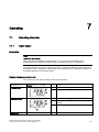
7.1
7.1.1
7.1.2
7.1.3
Operating elements......................................................................................................................91
Digital display ...............................................................................................................................91
Buttons .........................................................................................................................................93
Firmware version .........................................................................................................................94
7.2
7.2.1
7.2.2
7.2.3
Operating modes .........................................................................................................................94
Overview of operating modes ......................................................................................................94
Changing the operating mode......................................................................................................95
Description of operating modes ...................................................................................................96
7.3
Optimizing the controller data ......................................................................................................98
Functional safety.................................................................................................................................... 101
8.1
8.1.1
8.1.2
General safety notes..................................................................................................................101
Safety-instrumented system ......................................................................................................101
Safety Integrity Level (SIL).........................................................................................................102
8.2
8.2.1
8.2.2
8.2.3
8.2.4
Device-specific safety notes ......................................................................................................103
Range of applications for functional safety ................................................................................103
Safety function ...........................................................................................................................104
Settings ......................................................................................................................................105
Behavior in case of faults...........................................................................................................106
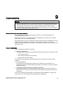
Commissioning ...................................................................................................................................... 107
9.1
Sequence of automatic initialization ..........................................................................................108
9.2
9.2.1
9.2.2
9.2.3
Commissioning linear actuators.................................................................................................114
Preparing linear actuators for commissioning............................................................................114
Automatic initialization of linear actuators..................................................................................115
Manual initialization of linear actuators......................................................................................117
9.3
9.3.1
9.3.2
9.3.3
Commissioning part-turn actuators............................................................................................120
Preparing part-turn actuators for commissioning.......................................................................120
Automatic initialization of part-turn actuators.............................................................................121
Manual initialization of part-turn actuators .................................................................................123
9.4
Copying the initialization data when replacing a positioner .......................................................126
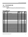
Parameterizing/addressing .................................................................................................................... 129
10.1
Parameter chapter .....................................................................................................................129
10.2
Configuration schematic for parameter operating principle .......................................................130
10.3
10.3.1
10.3.2
10.3.3
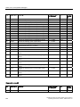
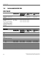
Overview of parameters.............................................................................................................131
Overview of parameters 1 to 5...................................................................................................131
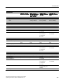
Overview of parameters 6 to 51.................................................................................................132
Overview parameters A to P ......................................................................................................135
10.4
10.4.1
10.4.1.1
10.4.1.2
10.4.2
10.4.2.1
10.4.2.2
10.4.2.3
10.4.2.4
10.4.2.5
10.4.2.6
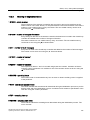
Description of parameters..........................................................................................................138
Description of parameters 1 through 5 ......................................................................................138
Description of parameters 1 and 2.............................................................................................138
Description of parameters 3 to 5................................................................................................140
Description of parameters 6 through 51 ....................................................................................141
Description of parameters 6.......................................................................................................141
Description of parameters 7.......................................................................................................141
Description of parameters 10 and 11.........................................................................................143
Description of parameters 12.....................................................................................................143
Description of parameters 13 through 33 ..................................................................................144
Description of parameters 34.....................................................................................................144
SIPART PS2 with and without HART communications
Operating Instructions, 09/2007, A5E00074631-07
7
Table of contents
10.4.2.7 Description of parameters 35 and 36........................................................................................ 145
10.4.2.8 Description of parameters 37 .................................................................................................... 145
10.4.2.9 Description of parameters 38 .................................................................................................... 146
10.4.2.10 Description of parameters 39 .................................................................................................... 147
10.4.2.11 Description of parameters 40 and 41........................................................................................ 147
10.4.2.12 Description of parameters 42 and 43........................................................................................ 148
10.4.2.13 Description of parameters 44 .................................................................................................... 149
10.4.2.14 Description of parameters 45 and 46........................................................................................ 150
10.4.2.15 Description of parameters 47 .................................................................................................... 150
10.4.2.16 Description of parameters 48 .................................................................................................... 151
10.4.2.17 Description of parameters 49 .................................................................................................... 151
10.4.2.18 Description of parameters 50 .................................................................................................... 152
10.4.2.19 Description of parameters 51 .................................................................................................... 152
10.4.3 Description of parameters A through P..................................................................................... 153
10.4.3.1 Description of parameter A ....................................................................................................... 153
10.4.3.2 Description of parameter b........................................................................................................ 156
10.4.3.3 Description of parameter C ....................................................................................................... 158
10.4.3.4 Description of parameter d........................................................................................................ 160
10.4.3.5 Description of parameter E ....................................................................................................... 161
10.4.3.6 Description of parameter F........................................................................................................ 162
10.4.3.7 Description of parameter G ....................................................................................................... 163
10.4.3.8 Description of parameter H ....................................................................................................... 165
10.4.3.9 Description of parameter J ........................................................................................................ 166
10.4.3.10 Description of parameter L........................................................................................................ 167
10.4.3.11 Description of parameter O ....................................................................................................... 169
10.4.3.12 Description of parameter P ....................................................................................................... 170
11
12
Alarm, error, and system messages ...................................................................................................... 173
11.1
11.1.1
11.1.2
11.1.3
11.1.4
Representation of system messages in the digital display ....................................................... 173
System messages before initialization...................................................................................... 173
System messages during initialization ...................................................................................... 174
System messages when exiting the Configuration mode ......................................................... 176
System messages during operation.......................................................................................... 176
11.2
11.2.1
11.2.2
11.2.3
11.2.4
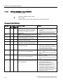
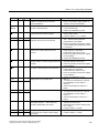
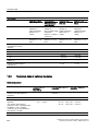
Diagnosis................................................................................................................................... 178
Display of diagnostics values .................................................................................................... 178
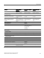
Overview of diagnostics values................................................................................................. 179
Meaning of diagnostics values.................................................................................................. 181
Meaning of diagnostic value 53 ................................................................................................ 187
11.3
11.3.1
11.3.2
11.3.3
11.3.4
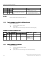
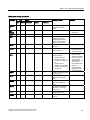
Online diagnostics..................................................................................................................... 187
Overview of online diagnostics ................................................................................................. 187
XDIAG parameter...................................................................................................................... 188
Overview of error codes ............................................................................................................ 188
Meaning of error codes ............................................................................................................. 190
11.4
11.4.1
11.4.2
11.4.3
11.4.4
11.4.5
11.4.6
Fault correction ......................................................................................................................... 193
Fault identification ..................................................................................................................... 193
Remedial measures table 1 ...................................................................................................... 193
Remedial measures table 2 ...................................................................................................... 195
Remedial measures table 3 ...................................................................................................... 196
Corrective measures Table 4 .................................................................................................... 196
Remedial measures table 5 ...................................................................................................... 197
Service and maintenance ...................................................................................................................... 199
12.1
8
Positioner in the metal enclosure and in the flameproof enclosure .......................................... 199
SIPART PS2 with and without HART communications
Operating Instructions, 09/2007, A5E00074631-07
Table of contents
12.2
13
Positioner in the plastic enclosure .............................................................................................200
Technical data ....................................................................................................................................... 201
13.1
General technical data ...............................................................................................................201
13.2
Technical data for SIPART PS2.................................................................................................204
13.3
Technical data of optional modules ...........................................................................................206
14
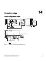
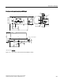
Dimension drawings .............................................................................................................................. 211
15
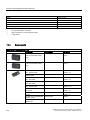
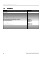
Scope of delivery/spare parts/accessories............................................................................................. 215
A
B
15.1
Overview ....................................................................................................................................215
15.2
Scope of delivery of basic unit ...................................................................................................217
15.3
Optional modules .......................................................................................................................217
15.4
Spare parts.................................................................................................................................218
15.5
Scope of delivery of small part sets ...........................................................................................220
15.6
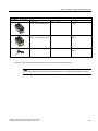
Accessories................................................................................................................................222
Appendix................................................................................................................................................ 223
A.1
Literature/catalogs/standards.....................................................................................................223
A.2
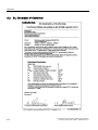
SIL Declaration of Conformity ....................................................................................................224
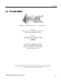
A.3
Test report (extract) ...................................................................................................................225
Abbreviations......................................................................................................................................... 229
Glossary ................................................................................................................................................ 231
Index...................................................................................................................................................... 239
SIPART PS2 with and without HART communications
Operating Instructions, 09/2007, A5E00074631-07
9
1
Introduction
1.1
Purpose of this documentation
This programming manual contains all information that you will require to commission and
use the device.
It is aimed at persons who install the device mechanically, connect it electrically,
parameterize and commission it, as well as at service and maintenance engineers.
This document also contains special information and safety notes that you will require when
using an SIL-certified device in safety-instrumented systems.
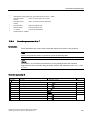
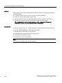
1.2
History
This history establishes the correlation between the current documentation and the valid
firmware of the device.
The documentation of this edition is applicable for the following firmware:
Edition
Firmware code
07
09/2007
FW: 4.00.00 and up
The most important changes in the documentation when compared with the respective
previous edition are given in the following table.
Edition
Remark
07
09/2007
Complete editorial reworking. Newly added content on the topics of natural gas
operation and functional safety.
SIPART PS2 with and without HART communications
Operating Instructions, 09/2007, A5E00074631-07
11
Introduction
1.3 Further information
1.3
Further information
Information
The contents of these instructions shall not become part of or modify any prior or existing
agreement, commitment or legal relationship. All obligations on the part of Siemens AG are
contained in the respective sales contract which also contains the complete and solely
applicable warranty conditions. Any statements contained herein do not create new
warranties or modify the existing warranty.
The content reflects the technical status at the time of printing. We reserve the right to make
technical changes in the course of further development.
Worldwide contact person
If you need more information or have particular problems which are not covered sufficiently
by the operating instructions, get in touch with your contact person. You can find contact
information for your local contact person in the Internet.
Product information on the Internet
The Programming Manual is an integral part of the companion CD, which may be ordered
separately. In addition, the Programming Manual is available on the Internet on the Siemens
homepage.
On the CD you will also find the technical data sheet containing the ordering data, the Device
Install software for SIMATIC PDM for subsequent installation and the required software.
See also
Contacts (http://www.siemens.com/processinstrumentation/contacts)
Product information on SIPART PS2 in the Internet (http://www.siemens.com/sipartps2)
Instructions and Manuals (http://www.siemens.com/processinstrumentation/documentation)
Environmental protection
Devices described in this programming manual can be recycled owing to the low content of
noxious substances in their version. Please contact a certified waste disposal company for
eco-friendly recycling and to dispose of your old devices.
12
SIPART PS2 with and without HART communications
Operating Instructions, 09/2007, A5E00074631-07
General safety notes
2.1
2
General information
This device left the factory free from safety problems. In order to maintain this status and to
ensure safe operation of the device, please observe the safety information and warnings
contained in these instructions.
2.2
Correct usage
The device may only be used for the purposes specified in these instructions.
Insofar as they are not expressly stated in these instructions, all changes to the device are
the sole responsibility of the user.
2.3
Laws and directives
Observe the test certification, provisions and laws applicable in your country during
connection, assembly and operation.
For hazardous areas, these are for example:
● IEC 60079-14 (international)
● National Electrical Code (NEC - NFPA 70) (USA)
● Canadian Electrical Code (CEC) (Canada)
● EN 60079-14 (formerly VDE 0165, T1) (EU, Germany)
● The working reliability regulation (Germany)
SIPART PS2 with and without HART communications
Operating Instructions, 09/2007, A5E00074631-07
13
General safety notes
2.4 Measures
2.4
Measures
For the sake of safety, the following precautions must be observed:
WARNING
Type of protection "pressure-proof encapsulation"
Devices with "pressure-proof encapsulation" protection may only be opened when off
circuit.
"Intrinsically safe" protection type
"Intrinsically-safe" devices lose their certification as soon as they are operated on circuits
which do not correspond with the test certification valid in their country. The "ia" protection
level of the device is lowered to the "ib" protection level if intrinsically safe circuits with the
"ib" protection level are connected.
Protection type "limited energy" nL (zone 2)
Devices with "limited energy" may be connected and disconnected while in operation.
Protection type "non-sparking" nA (zone 2)
Devices with "non-sparking" protection may only be connected and disconnected when off
circuit.
Exceptions:
Connection lines with unlimited energy as well as internal connectors may be connected or
disconnected under voltage only in the following cases:
• During installation
• During maintenance
• During repairs
WARNING
Exposure to aggressive and hazardous media
The device can be operated both at high pressure and with aggressive and hazardous
media. Therefore, improper use of this device may lead to serious injury and or
considerable damage to property. Above all, it must be noted when the device was in use
and is to be exchanged.
CAUTION
For versions 6DR5a*b-*Gc**-****, where a = 0, 2, 5, 6; b = 0, 1; c = G, N, M, P, Q, the
following is applicable:
The device must be protected against power surges of over one joule.
For versions 6DR5a*b-*Gc**-****, where a = 0, 2, 5, 6; b = 0; c = G, N, M, P, Q, the
following is applicable:
The maximum torque on the thread of the cable gland should not exceed 67 Nm.
14
SIPART PS2 with and without HART communications
Operating Instructions, 09/2007, A5E00074631-07
General safety notes
2.5 Qualified Personnel
CAUTION
Electrostatic Sensitive Devices (ESD)
This device contains electrostatic sensitive devices. Electrostatic sensitive devices may be
destroyed by voltages that are undetectable to a human. Voltages of this kind occur as
soon as a component or an assembly is touched by a person who is not grounded against
static electricity. The damage to a module as a result of overvoltage cannot usually be
detected immediately. It may only become apparent after a long period of operation.
Therefore, avoid electrostatic charge.
2.5
Qualified Personnel
Qualified personnel are people who are familiar with the installation, mounting,
commissioning, and operation of the product. These people have the following qualifications:
● They are authorized, trained or instructed in operating and maintaining devices and
systems according to the safety regulations for electrical circuits, high pressures and
aggressive as well as hazardous media.
● For explosion-proof devices: They are authorized, trained, or instructed in carrying out
work on electrical circuits for hazardous systems.
● They are trained or instructed in maintenance and use of appropriate safety equipment
according to the safety regulations.
2.6
SIL applications
The SIPART PS2 positioner, in variants 6DR501*, 6DR511*, 6DR521*, and 6DR531* (that
is, with 0/4 to 20 mA excitation signal in a single-acting version), is also suitable for
positioning on control valves with pneumatic drives. Control valves with pneumatic drives
must satisfy the particular requirements of safety technology up to SIL 2 per IEC 61508/IEC
61511-1.
See also
Functional safety in process instrumentation (http://www.siemens.com/SIL)
SIPART PS2 with and without HART communications
Operating Instructions, 09/2007, A5E00074631-07
15
Description
3.1
3
Function
● The electropneumatic positioner, in combination with the drive, forms a regulation
system. The current position of the drive is detected using a servo potentiometer and is
sent back as actual value x. The actual and target values are simultaneously displayed
on the digital display.
● The setpoint w forms a current applied to the positioner, which in two-wire mode is also
used to power the positioner. In 3- and 4-wire mode, power is supplied through a 24-V
power input.
● The positioner works as a predictive five-point positioner, through whose output value
±Δy the integrated valves can be controlled by pulse length modulation.
● These positioning signals cause pressure changes in the drive chamber(s) and thus a
repositioning of the drive until the regulation deviation returns to zero.
● Using three buttons and a digital display with the housing cover removed, operation
(manual mode) and configuration (structuring, initialization, and parameterization) can be
performed.
● By default, the basic unit has a binary input (BE1). This binary input can be individually
configured and used e.g. to block the control levels.
● To be able to use the positioner in a variety of mechanically different rotational and linear
actuators, it has a friction clutch and a switchable gear.
3.2
Structure
3.2.1
Overview of structure
The following chapters describe the mechanical and electrical structure, components, and
principle functionality of the positioner.
The positioner is available in the following configurations:
● SIPART PS2 without explosion protection in metal or plastic housing
● SIPART PS2 with EEx ia/ib protection in metal or plastic housing
● SIPART PS2 with EEx d protection in explosion-proof housing
SIPART PS2 with and without HART communications
Operating Instructions, 09/2007, A5E00074631-07
17
Description
3.2 Structure
The positioner is used to adjust and regulate pneumatic drives. The positioner works
electropneumatically, using compressed air as auxiliary power. The positioner can e.g.
regulate valves with:
● linear actuator
● Part-turn actuator VDI/VDE 3845
For linear actuators, there are various add-on extensions available:
● NAMUR or IEC 534
● Integrated addition to ARCA
● Integrated addition to SAMSON in non–explosion-proof housing
You can mount the positioner on the usual drives and operate it with the usual drives.
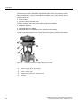
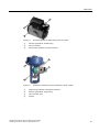
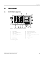
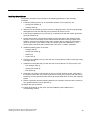
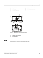
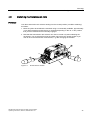
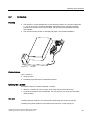
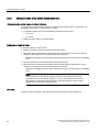
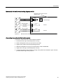
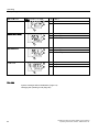
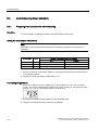
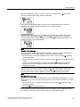
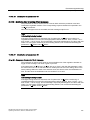
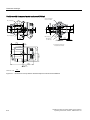
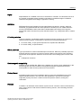
Figure 3-1
18
Positioner attached to a single-acting linear actuator
①
Pressure gauge block, single-acting
②
Valve
③
Yoke / actuator yoke
④
Single-acting positioner in metal enclosure
⑤
Actuator
SIPART PS2 with and without HART communications
Operating Instructions, 09/2007, A5E00074631-07
Description
3.2 Structure
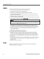
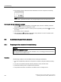
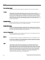
Figure 3-2
①
Positioner attached to double-acting part-turn actuator
Pressure gauge block, double-acting
②
Part-turn actuator
③
Double-acting positioner in plastic enclosure
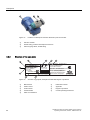
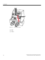
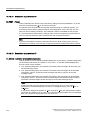
Figure 3-3
Positioner in flameproof enclosure attached to linear actuator
①
Single-acting positioner in flameproof enclosure
②
Pressure gauge block, single-acting
③
Yoke / actuator yoke
④
Actuator
SIPART PS2 with and without HART communications
Operating Instructions, 09/2007, A5E00074631-07
19
Description
3.2 Structure
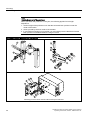
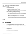
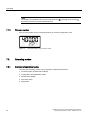
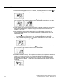
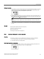
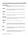
Figure 3-4
3.2.2
Positioner in flameproof enclosure attached to part-turn actuator
①
Part-turn actuator
②
Double-acting positioner in flameproof enclosure
③
Pressure gauge block, double-acting
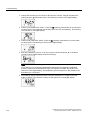
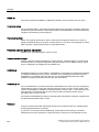
Structure of the type plate
SIPART PS2 HART Positioner
6DR5210-0EG00-0AA0
II 2 G EEx ia/ib II C T6/T5/T4
Ta = -30 ... 50/65/80°C
Uh= 18...30V
Iw = 0/4...20mA
TÜV 00 ATEX 1654
Made in France
①
20
IP66
NEMA Type 4x
p = 1,4 ... 7bar
F-Nr.: N1-S610-7534410
IECEx TUN 04.0018
Ex ia/ib IIC T6..T1
Technical data and temperature classes see certificate
CL I, DIV 2, GP ABCD T6/T5/T4
CL I, ZN 2, GP IIC T6/T5/T4
(IS) CL I, DIV 1, GP ABCD T6/T5/T4
(FM)/(CSA) CL I, ZN 1, AEx ib IIC / Ex ib IIC T6/T5/T4
Ta = -30 ... 50(T6)/65(T5)/80(T4) °C
Install per Contr. Dwg. A5E00065622D
Siemens AG, D-76181 Karlsruhe
www.siemens.com/sipartps2
FM
$33529('
Figure 3-5
0044
Structure of type plate, example of the EEx ia/ib degree of protection
Manufacturer
⑥
Fabrication number
②
Product name
⑦
Approvals
③
Order number
⑧
Degree of protection
④
Technical data
⑨
Consult operating instructions
⑤
Place of manufacture
SIPART PS2 with and without HART communications
Operating Instructions, 09/2007, A5E00074631-07
Description
3.3 Operation with natural gas
3.3
Operation with natural gas
3.3.1
Safety notes for operation with natural gas
When operating the positioner with natural gas, you must follow and adhere to the following
safety notes:
WARNING
Operation with natural gas
1. Only the "EEx ia" version of the positioner and optional modules with the "EEx ia" type
of protection may be operated with natural gas. Positioners with other types of
protection, e.g. flameproof enclosure or versions for zones 2 and 22 are not permitted.
2. Do not operate the positioner with natural gas in closed spaces.
3. Natural gas is continuously blown off in the servo-drive depending on the model. Special
care must therefore be taken during maintenance activities near the positioner. Always
ensure that the immediate surroundings of the positioner are adequately ventilated.
4. The mechanical limit switch module may not be used when operating the positioner with
natural gas.
5. Depressurize the devices operated with natural gas adequately during maintenance
activities. Open the cover in an explosion-free atmosphere and depressurize the device
for at least two minutes.
3.3.2
Natural gas as an actuator medium
Introduction
Normally, you operate the positioner with compressed air. Natural gas has been approved as
an actuator medium for intrinsically safe positioners with the "EEx ia" type of protection.
Note
Quality of natural gas
Only use natural gas which is clean, dry and free from additives.
Functional principle
The positioner releases the used natural gas through the exhaust air outlet E. The exhaust
air outlet E is equipped with an attenuator.
As an alternative to this standard configuration, the exhaust air outlet can be replaced with a
G¼ screwed fitting. You have to dismantle the attenuator for this purpose.
SIPART PS2 with and without HART communications
Operating Instructions, 09/2007, A5E00074631-07
21
Description
3.3 Operation with natural gas
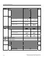
Maximum values for escaping natural gas
Natural gas escapes parallel to the exhaust air outlet E:
● From the enclosure vent at the bottom side of the device
● From the control air outlet near the pneumatic connections
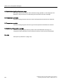
This escaping natural gas cannot be collected and carried off. Please refer to the following
table for the maximum bleeding values.
Bleeding process
Bleed the enclosure volume through the bottom
side of the device. Purge air switch is at "IN":
Bleed through the control air outlet near the
pneumatic connections:
Bleed through the exhaust air outlet E
Operating
mode
6DR5x1x-xExxx 6DR5x2x-xExxx
Single-acting
Double-acting
[Nl/min]
[Nl/min]
Operation,
typical
0.14
0.14
Operation,
max.
0.60
0.60
Error case,
max.
60.0
60,0
Operation,
typical
1.0
2.0
Operation,
max.
8.9
9.9
Error case,
max.
66.2
91.0
Operation,
max.
358.21)
3391),
1.26
1.23
Error case,
max.
Volume
1)
Max. [l]
Depending on the actuating pressure and volume of the actuator as well as the frequency of
control. The maximum flow rate is 470 Nl/min at a differential pressure of 7 bar.
See also
Safety notes for operation with natural gas (Page 21)
Pneumatic connection on the standard controller (Page 25)
22
SIPART PS2 with and without HART communications
Operating Instructions, 09/2007, A5E00074631-07
Description
3.4 Device components
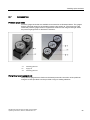
3.4
Device components
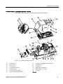
3.4.1
Overview of device components
r
r
%(
r
:
P$
P$
:
r
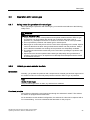
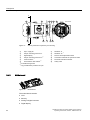
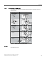
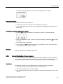
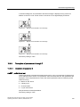
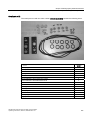
Figure 3-6
①
View of basic positioner with cover open
Input: supply air
⑩
Transmission ratio selector
②
Output: Actuating pressure Y1
⑪
Friction clutch adjustment wheel
③
Digital display
⑫
Motherboard
④
Output: Actuating pressure Y2 1)
⑬
Connection terminals for optional modules
⑤
Control buttons
⑭
Dummy plug
⑥
Restrictor
⑮
Cable gland
⑦
Restrictor Y1
⑯
Terminal label on cover
⑧
Restrictor Y2
⑰
Purging air selector
⑨
Sound absorber
1)
1)
for double-acting drives
SIPART PS2 with and without HART communications
Operating Instructions, 09/2007, A5E00074631-07
23
Description
3.4 Device components
$
6FKQLW$$
138
10
238
9
1
+
$
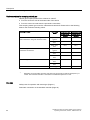
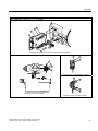
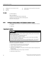
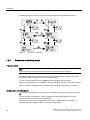
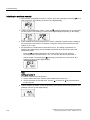
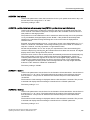
Figure 3-7
3.4.2
View of positioner in explosion-proof housing
①
Input: supply air
⑦
Restrictor Y1
②
Output: Actuating pressure Y1
⑧
Restrictor Y2 1)
③
Digital display
⑨
Friction clutch adjustment wheel
④
Output: Actuating pressure Y2
⑩
Connection terminals for optional modules
⑤
Control buttons
⑪
Terminals standard controller
⑥
Transmission ratio selector 2)
⑫
Safety catch
1)
1)
for double-acting drives
2)
only possible when positioner is open
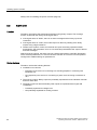
Motherboard
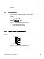
Figure 3-8
Motherboard
The motherboard contains:
● CPU
● Memory
● Analog-to-digital converter
● Digital display
24
SIPART PS2 with and without HART communications
Operating Instructions, 09/2007, A5E00074631-07
Description
3.4 Device components
● Buttons
● Terminal strips to connect the optional module to the motherboard
3.4.3
Electrical connections
Connecting terminals of the standard controller, the Iy and the alarm optional module are
provided at the left front edges, and are arranged in a staircase-shape.
The module cover protects components from being pulled out and prevents an incorrect
assembly.
1
10
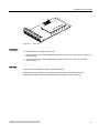
Figure 3-9
Connecting terminals of the flameproof enclosure
①
Connecting terminals of optional modules
②
Connecting terminals of standard controller
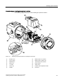
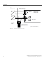
3.4.4
Pneumatic connections
3.4.4.1
Pneumatic connection on the standard controller
Structure
The pneumatic connections are provided on the right side of the positioner.
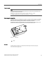
Figure 3-10
Pneumatic connection on the standard controller
①
Actuating pressure Y1 for single and double-acting actuators
②
Feedback shaft
③
Supply air PZ
④
Actuating pressure Y2 for double-acting actuators
⑤
Exhaust air outlet with an attenuator at the bottom side of the device
SIPART PS2 with and without HART communications
Operating Instructions, 09/2007, A5E00074631-07
25
Description
3.4 Device components
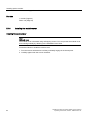
3.4.4.2
Pneumatic connection in the flameproof enclosure
Structure
The pneumatic connections are provided on the right side of the positioner.
Figure 3-11
①
Pneumatic connection in the flameproof enclosure
Restrictor Y2 *)
⑤
Actuating pressure Y1
②
Restrictor Y1
⑥
Exhaust air outlet E
③
Actuating pressure Y2 *)
⑦
Enclosure ventilation (2x)
④
Supply air PZ
*) for double-acting actuators
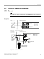
3.4.4.3
Pneumatic connection versions
Overview
For the integrated attachment for single-action linear actuators, the following pneumatic
connections are provided at the rear side of the standard controller:
● Actuating pressure Y1
● Exhaust air outlet
These connections are sealed with screws when the device is delivered.
The exhaust air outlet is corrosion-resistant for the blanketing of the pick-up room and the
spring chamber with dry instrument air.
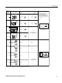
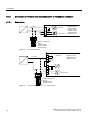
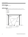
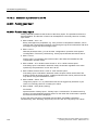
The following overview diagram shows the pneumatic connection versions for different
actuator types, regulating action and safety position after an auxiliary power supply failure.
26
SIPART PS2 with and without HART communications
Operating Instructions, 09/2007, A5E00074631-07
Description
3.4 Device components
3RVLWLRQLQJ
SUHVVXUH
&RQQHFWLRQ
6DIHW\SRVLWLRQDIWHUSRZHUIDLOXUH
$FWXDWRUW\SH
SQHXPDWLF
HOHFWULFDO
<
&ORVHG
&ORVHG
&ORVHG
,QSDUWWXUQDFWXDWRUVWKH
GLUHFWLRQRIURWDWLRQ
FRXQWHUFORFNZLVHORRNLQJ
RQWRWKHDFWXDWLQJVKDIWRI
WKHYDOYHLVXVXDOO\GHILQHG
DVಯ2SHQರ
2SHQ
<
2SHQ
&ORVHG
2SHQ
2SHQ
<
2SHQ
&ORVHG
2SHQ
<
&ORVHG
2SHQ
/DVWSRVLWLRQ
EHIRUHSRZHUIDLOXUH
<
&ORVHG
<
&ORVHG
<
2SHQ
XS
GRZQ
'RZQ
'RZQ
8S
8S
<
XS
GRZQ
<
<
XS
GRZQ
8S
XS
<
<
GRZQ
/DVWSRVLWLRQ
EHIRUHSRZHUIDLOXUH
XS
'RZQ
GRZQ
Figure 3-12
Regulating action of pneumatic connection
SIPART PS2 with and without HART communications
Operating Instructions, 09/2007, A5E00074631-07
27
Description
3.4 Device components
3.4.5
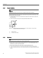
Purge air switching
Note
Equipment
Versions with flameproof enclosures are not equipped with purge air switching.
When the enclosure is open, the purge air switch above the pneumatic terminal strip on the
pneumatic block can be accessed.
● In the IN position, the enclosure is flushed from inside with a small volume of clean and
dry instrument air.
● In the OUT position, the purge air is directly directed towards outside.
Figure 3-13
3.4.6
Purge air switch on the pneumatic block; view of the positioner on the pneumatic
connection side when the cover is open
①
Purge air switch
②
Pneumatic terminal strip
Restrictors
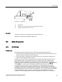
Note
The exhaust air valve is always open in the de-energized state.
● Reduce the air output to achieve actuating times of T > 1.5 s for small actuators. Use
restrictors Y1 ① and Y2 ② for this purpose.
● When turned clockwise, they reduce the air output and finally shut it off.
● In order to set the restrictors, we recommend closing them and then opening slowly.
● In case of double-acting valves, ensure that both restrictors have approximately the same
setting.
28
SIPART PS2 with and without HART communications
Operating Instructions, 09/2007, A5E00074631-07
Description
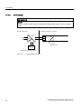
3.5 Mode of operation
Figure 3-14
Restrictors
①
Restrictor Y1
②
Restrictor Y2, only in the version for double-acting actuators
③
Hexagon socket-head screw 2.5 mm
See also
Pneumatic connection in the flameproof enclosure (Page 26)
Sequence of automatic initialization (Page 108)
3.5
Mode of operation
3.5.1
Control loop
Control loop
The electropneumatic positioner forms a control loop with the pneumatic drive:
● The actual value x represents the position of the drive spindle for linear actuators or the
position of the drive shaft for part-turn actuators.
● The control value w represents the positioning current of a closed-loop controller or a
manual control station from 0/4 to 20 mA.
The lifting or rotary movement of the actuator is transferred to a high-quality conductive
plastic potentiometer using suitable attachments, feedback shaft and a backlash-free,
switchable gear drive, and then to the analog input of the microcontroller. The current
position can also be forwarded to the positioner using an external sensor. A Non-Contacting
Position Sensor is used to record the lifting or rotation angle directly on the actuator.
If required, the microcontroller corrects the angle error of the feedback lever bracket,
compares the potentiometer voltage as an actual value x with the setpoint w that is fed
through terminals 3 and 7, and calculates the controller output increment ±∆y. Depending on
the magnitude and the direction of the control deviation (x-w), the piezo advance controlled
supply or exhaust air valve is opened. The actuator volume integrates the controller
increment for the actuating pressure y which is proportional to the drive rod or the drive
SIPART PS2 with and without HART communications
Operating Instructions, 09/2007, A5E00074631-07
29
Description
3.5 Mode of operation
shaft. This controller increment change the actuating pressure until the control deviation
becomes zero.
Pneumatic actuators are available in single and double-acting versions. Only one pressure
chamber is ventilated and depressurized in case of a single-acting version. The pressure
developed works against a spring. Two pressure chambers work against each other in case
of a double-acting version. When ventilating the volume of the one, the volume of the other is
depressurized.
See also
Block circuit diagram for signal-acting or dual-acting drives (Page 31)
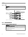
3.5.2
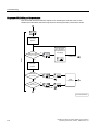
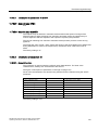
Control algorithm
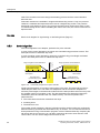
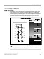
The control algorithm is an adaptive, predictive five-point controller.
In case of large control deviations, the valves are controlled using permanent contact. This
takes place in the so-called fast step zone.
In case of medium control deviations, valves are controlled using pulse-length modulated
pulses. This takes place in the so-called slow step zone.
[G
YDOYHRSHQV
VORZVWHS]RQH
YDULDEOHGXW\F\FOH
Figure 3-15
GXW\F\FOH
WR
TXLFNPRYHPHQW]RQH
SHUPDQWHQWFRQWDFW
UDQJHRISRVLWLYHFRQWUROGLIIHUHQFH
TXLFNPRYHPHQW]RQH
SHUPDQWHQWFRQWDFW
[G
YDOYHFORVHV
GHDG]RQH
UDQJHRIQHJDWLYHFRQWUROGLIIHUHQFH
VORZVWHS]RQH
YDULDEOHGXW\F\FOH
Functional principle of five-point controller
Small control deviations do not send control pulses in the zone. This takes place in the socalled adaptive dead zone. The dead zone adaptation and the continuous adaptation of
minimum pulse lengths in the automatic mode ensure the best possible control accuracy with
the smallest number of operating cycles. The start parameters are determined during the
initialization phase and stored in the non-volatile memory. The most important start
parameters are:
● The real actuator travel with mechanical end stops
● Actuating times
● The dead zone size
The number of fault messages, changes in direction and the stroke number are continuously
determined during operation and saved after every 15 minutes. You can read and document
these parameters using communication programs such as PDM and AMS. By comparing the
old values with the current ones, you can draw conclusions about the wear and tear of the
control valve. You can use the diagnostics function for this.
30
SIPART PS2 with and without HART communications
Operating Instructions, 09/2007, A5E00074631-07
Description
3.5 Mode of operation
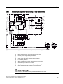
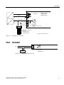
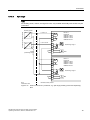
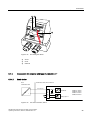
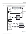
3.5.3
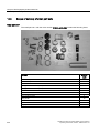
Block circuit diagram for signal-acting or dual-acting drives
+$57
VXSSO\DLU
%(
\
\
S=
, :
([KDXVWDLU
9
S
9
S
:
$
'
S
0LFUR
FRQWUROOHU
, :
S
$
\
'
8
([KDXVW
DLU
:
[
[
8
8
,
%(
$
$
S
$
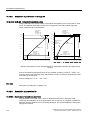
Figure 3-16
$
S
+XE
S
+XE
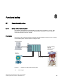
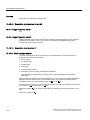
Block circuit diagram for the electropneumatic positioner, functional diagram
①
Basic circuit board with microcontroller and input circuit
②
Control pad with digital display and buttons
③
Piezo valve unit, always installed
④
Valve unit in dual-action positioner always installed
⑤
Iy module for positioner
⑥
Alarm module for three alarm outputs and one binary input
⑦
SIA module (slit initiator alarm module)
⑧
Spring-loaded pneumatic positioning drive (single-acting)
⑨
Spring-loaded pneumatic positioning drive (dual-action)
Note
Alarm module and SIA module
Alarm module ⑥ and SIA module ⑦ can only be alternatively used.
SIPART PS2 with and without HART communications
Operating Instructions, 09/2007, A5E00074631-07
31
Description
3.5 Mode of operation
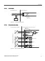
3.5.4
Mode of operation of the HART function
Note
• Operation at the positioner has priority over specifications from the HART communicator.
• Failure of the auxiliary power to the positioner also interrupts communications.
Function
The positioner is also available with built-in HART functionality. The HART protocol allows
you to communicate with your device through a handheld communicator, PC, or
programming unit. You can do the following with your device:
● Convenient configuration
● Store configurations
● Call up diagnostic data
● Show online measured values
Communication takes place as frequency modulation on the existing signal lines for the
control values of 4 to 20 mA.
The positioner is integrated into the following parameterization tools:
● Handheld Communicator
● PDM (Process Device Manager)
● AMS (Asset Management System)
● Cornerstone (without diagnostic values/functions)
32
SIPART PS2 with and without HART communications
Operating Instructions, 09/2007, A5E00074631-07
4
Mounting
4.1
Safety notes for installation
WARNING
Mechanical impact effect
Protect the 6DR5**0-*G***-**** version of the positioner from mechanical impact effects that
are greater than 1 Joule; this ensure adherence to the IP66 degree of protection.
When installing, observe the following sequence imperatively to avoid injuries or
mechanical damage to the positioner/mounting kit:
1. Mount the positioner mechanically.
2. Connect the electrical auxiliary power supply.
3. Connect the pneumatic auxiliary power supply.
4. Commission the positioner.
WARNING
Assembling the components
When assembling components, ensure that only those positioners and optional modules
are combined with each other that are approved for the corresponding operating range.
This condition is particularly applicable for the safe operation of the positioner in the areas
of zones 1, 2 and 22, where the atmosphere may be potentially explosive. Observe the
device categories 2 and 3 of the device itself and its optional modules imperatively.
SIPART PS2 with and without HART communications
Operating Instructions, 09/2007, A5E00074631-07
33
Mounting
4.2 Installing the linear actuator
CAUTION
Humid environment/dry compressed air
Install the positioner in a humid environment such that the positioner shaft does not freeze
at low ambient temperatures.
Ensure that water does not seep through an open enclosure or an open gland. Water may
seep through if the positioner is not installed and connected on-site immediately and finally.
As a general rule, the positioner must be operated only with dry compressed air. Therefore,
use the customary water separator. An additional dryer is required in extreme cases. The
use of dryers is especially important when you operate the positioner at low ambient
temperatures. Set the Purge air switch to the "OUT" position when installing on the
pneumatic block, above the pneumatic connections.
4.2
Installing the linear actuator
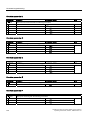
Conditions
For linear actuators, use the "linear actuator" mounting kit or the integrated attachment.
You require different installation parts depending on the selected actuator type. Keep the
suitable installation parts ready:
34
Actuator type
Required installation components
Actuator with fin
•
•
•
Hexagon bolt ⑧
Washer ⑪
Spring lock washer ⑩
Actuator with plane surface
•
•
•
Four hexagon bolts ⑧
Washer ⑪
Spring lock washer ⑩
Actuator with columns
•
•
•
•
Two U–bolts ⑦
Four hexagon nuts ⑳
Washer ⑪
Spring lock washer ⑩
SIPART PS2 with and without HART communications
Operating Instructions, 09/2007, A5E00074631-07
Mounting
4.2 Installing the linear actuator
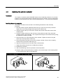
Installing the positioner
The position numbers in the text refer to the following illustrations of the assembly
procedure.
1. Install the clamping pieces ③ on the actuator spindle. For this purpose, use:
– Spring lock washers ⑯
– Hexagon bolts ⑰
2. Slide the pick-up bracket ② into the notches of clamping pieces. Set the required length
and tighten the bolts such that the pick-up bracket can still be moved.
3. Insert the pre-installed pin ④ in the lever ⑥. Install the lever with the washer ⑫ and the
spring lock washer ⑭.
4. Set the stroke value. Use the value specified on the type plate of the actuator for this
purpose. If none of the values on the scale matches the value on the type plate of the
actuator, select the next higher scaling value. Position the pin center on the matching
value on the scale. If you need the value of actuator travel after initialization in mm:
ensure that the set stroke value matches the value of the "3.YWAY" parameter.
5. Install the following parts on the lever:
– Hexagon bolt ⑰
– Spring lock washer ⑯
– Washer ⑫
– Square nut ⑲
6. Push the pre-installed lever up to the end stop on the positioner shaft. Fix the lever using
a hexagon bolt ⑰.
7. Install the mounting bracket ① at the rear side of the positioner. For this purpose, use:
– Two hexagon bolts ⑨
– Spring lock washer ⑩
– Flat washer ⑪
8. Select the row of holes. The selection of the row of holes depends on the yoke width of
the actuator. Select the row of holes such that the carrier pin ④ meshes with the pick-up
bracket ② near the spindle. Ensure that the pick-up bracket does not touch the clamping
pieces.
9. Keep the positioner and the fastening bracket on the actuator. Ensure that the carrier pin
④ is guided inside the pick-up bracket ②.
10.Tighten the pick-up bracket.
11.Fasten the positioner on the yoke. Use the installation parts suitable for the
corresponding actuator.
SIPART PS2 with and without HART communications
Operating Instructions, 09/2007, A5E00074631-07
35
Mounting
4.2 Installing the linear actuator
Note
Height adjustment of the positioner
When you fasten the positioner on the yoke, the following applies for its height
adjustment:
1. Set the height of the positioner such that the horizontal lever position is near the
center of the stroke.
2. Orient yourself by the lever scale of the actuator.
3. If symmetrical mounting is not possible, you must always ensure that the horizontal
lever position is maintained within the range of stroke.
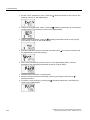
Assembly procedure: positioner with linear actuator
r
r
Assembly procedure: linear actuator without flameproof enclosure
36
SIPART PS2 with and without HART communications
Operating Instructions, 09/2007, A5E00074631-07
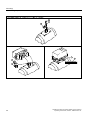
Mounting
4.2 Installing the linear actuator
Assembly procedure: positioner with linear actuator
Assembly procedure: linear actuator with flameproof enclosure
Mounting on the yoke with plane surface
Mounting on the yoke with fin
SIPART PS2 with and without HART communications
Operating Instructions, 09/2007, A5E00074631-07
Mounting on the yoke with columns
37
Mounting
4.2 Installing the linear actuator
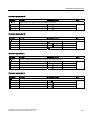
"Linear actuator IEC 534 (3 mm to 35 mm)" mounting kit 6DR4004-8V and 6DR4004-8L
Sr. No. *)
Quantity
Name
Note
①
1
NAMUR mounting bracket
IEC 534
Standardized connection point for mount with fin, column or plane
surface
②
1
Pick-up bracket
Guide the pulley with the carrier pin and rotates the lever arm.
③
2
Clamping piece
Installs the pick-up bracket on the actuator spindle
④
1
Carrier pin
Installation with pulley ⑤ on lever ⑥
⑤
1
Pulley
Installation with carrier pin ④ on lever ⑥
⑥
1
NAMUR lever
For the range of stroke from 3 mm to 35 mm
The 6DR4004–8L lever is additionally required for ranges of stroke
> 35 mm to 130 mm (not in the scope of delivery).
⑦
2
U–bolts
Only for actuators with columns
⑧
4
Hexagon bolt
M8 x 20 DIN 933–A2
⑨
2
Hexagon bolt
M8 x 16 DIN 933–A2
⑩
6
Spring lock washer
A8 - DIN 127–A2
⑪
6
Flat washer
B8.4 - DIN 125–A2
⑫
2
Flat washer
B6.4 - DIN 125–A2
⑬
1
Spring
VD-115E 0.70 x 11.3 x 32.7 x 3.5
⑭
1
Spring lock washer
A6 - DIN 137A–A2
⑮
1
Lock washer
3,2 - DIN 6799–A2
⑯
3
Spring lock washer
A6 - DIN 127–A2
⑰
3
Socket cap screw
M6 x 25 DIN 7984–A2
⑱
1
Hexagon nut
M6 - DIN 934–A4
⑲
1
Square nut
M6 - DIN 557–A4
⑳
4
Hexagon nut
M8 - DIN 934–A4
the serial numbers refer to the images of the description of the assembly procedure with
linear actuator.
*)
38
SIPART PS2 with and without HART communications
Operating Instructions, 09/2007, A5E00074631-07
Mounting
4.3 Installing the part-turn actuator
4.3
Installing the part-turn actuator
Conditions
You require an actuator-specific VDI/VDE 3845 mount to install the positioner on a part-turn
actuator. The mount and the bolts are included in the scope of delivery of the corresponding
actuator. Ensure that the mount has a sheet metal thickness of > 4 mm and reinforcements.
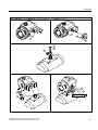
Installing the part-turn actuator
The position numbers in the text refer to the following illustrations of the assembly
procedure.
1. Rest the actuator-specific VDI/VDE 3845 mount ⑨ on the rear side of the positioner.
Tighten the mount using hexagon bolts ⑭ and lock washers ⑮.
2. Stick the pointer mark ⑥ on the mount. Position the pointer mark at the center of the
centering hole.
3. Push the coupling wheel up to the end stop on the positioner shaft. Then retract the
coupling wheel by approximately 1 mm. Tighten the hexagon socket-head screw ⑱ using
the machinist's wrench provided.
4. Place the carrier ③ on the shaft stump of the actuator. Tighten the carrier using the
socket cap screw ⑯ and the washer ⑰.
5. Place the positioner and the mount on the actuator carefully. The pin of the coupling
wheel must fit in the carrier while doing so.
6. Align the positioner/mount unit at the center of the actuator.
7. Tighten the positioner/mount unit. Initialize the positioner.
8. Initialize the positioner.
9. After commissioning, drive the positioner to the end position.
10.Stick the scale ⑤ with the direction of rotation or the swivel range on the coupling wheel
②. The stickers with scale are self-adhesive.
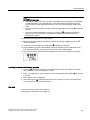
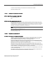
Assembly procedure for the positioner with part-turn actuator
SIPART PS2 with and without HART communications
Operating Instructions, 09/2007, A5E00074631-07
39
Mounting
4.3 Installing the part-turn actuator
Assembly procedure for the positioner with part-turn actuator
40
SIPART PS2 with and without HART communications
Operating Instructions, 09/2007, A5E00074631-07
Mounting
4.3 Installing the part-turn actuator
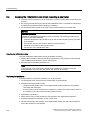
Assembly procedure for the positioner with part-turn actuator and flameproof enclosure
SIPART PS2 with and without HART communications
Operating Instructions, 09/2007, A5E00074631-07
0% 20 40 60 80 100%
41
Mounting
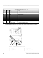
4.3 Installing the part-turn actuator
"Part-turn actuator" mounting kit 6DR4004–8D
Sr. No.
Name
Note
②
1
Coupling wheel
Installation on the position feedback shaft of the positioner
③
1
Carrier
Installation on the shaft stump of the actuator
④
1
Multiple plate
Display of the actuator position, consists of scale ⑤ and pointer mark
⑥
⑤
8
Scale
Different divisions
⑥
1
Pointer mark
Reference arrow for scale
⑭
4
Hexagon bolt
DIN 933 - M6 x 12
⑮
4
Lock washer
S6
⑯
1
Socket cap screw
DIN 84 - M6 x 12
⑰
1
Washer
DIN 125 - 6,4
⑱
1
Hexagon socket-head
screw
Pre-installed with coupling wheel
⑲
1
Machinist's wrench
For hexagon socket-head screw ⑱
*)
Quantity
The serial numbers refer to the images of the description of the assembly procedure with part-turn actuator with
and without flameproof enclosure.
$
%
Figure 4-1
42
Installed positioner for part-turn actuators
①
Positioner
⑩
Feedback shaft
②
Coupling wheel
⑭
Hexagon bolt - M6 x 12
③
Carrier
⑮
Lock washer S6
SIPART PS2 with and without HART communications
Operating Instructions, 09/2007, A5E00074631-07
Mounting
4.3 Installing the part-turn actuator
④
Part-turn actuator
⑯
Socket cap screw - M6 x 12
⑤
Scale
⑰
Washer
⑥
Pointer mark
⑱
Hexagon socket-head screw
⑨
VDI/VDE 3845 mount
!PP
0
D
E
D E 6,5 (0.26)
Ø35 (1.38)
F05-Lkr.-Ø50 (1.97)
Figure 4-2
Dimensions of mount (actuator-dependant)
①
Fastening plane of positioner
②
Part-turn actuator
See also
Preparing part-turn actuators for commissioning (Page 120)
SIPART PS2 with and without HART communications
Operating Instructions, 09/2007, A5E00074631-07
43
Mounting
4.4 Using the positioner in a humid environment
4.4
Using the positioner in a humid environment
Introduction
CAUTION
Never clean the positioner with a high pressure cleaner since the IP66 degree of protection
is not sufficient for this.
This information contains important notes for the installation and operation of the positioner
in a wet environment with frequent and heavy rains and/or continuous tropical dew. The IP66
degree of protection is no longer adequate in this environment, especially when there is a
risk of water freezing.
Favorable and unfavorable mounting positions
Avoid the unfavorable mounting positions:
● To prevent fluids seeping through during normal operation of the device, e.g. through
exhaust air openings.
● Otherwise the digital display becomes poorly legible.
Figure 4-3
Favorable and unfavorable mounting positions
Additional measures to prevent liquids from seeping through
Take additional measures to prevent liquids from seeping through if the conditions force you
to operate the positioner in an unfavorable mounting position.
Additional measures required to prevent liquids from seeping through depend on the
selected mounting position. You may also require:
● Gland with sealing ring, e.g. FESTO: CK - 1 / 4-PK-6
● Approximately 20 to 30 cm plastic hose, e.g. FESTO: PUN - 8 x 1.25 SW
● Cable tie; the number and the length depend on the local conditions.
44
SIPART PS2 with and without HART communications
Operating Instructions, 09/2007, A5E00074631-07
Mounting
4.5 Notes for using positioners that are exposed to strong accelerations or vibrations
Procedure
1. Install the casing such that rain water or condensate running along the pipes can be
drained before the terminal strip of the positioner.
2. Check the seals of electrical connections for perfect fitting.
3. Check the seal in the enclosure cover for damage and contaminations. Clean and/or
replace if required.
4. Install the positioner such that the sintered bronze attenuator at the bottom side of the
enclosure points downwards in the vertical mounting position. If this is not possible,
replace the attenuator with a suitable gland having a plastic hose.
Procedure for installing the plastic hose on the gland
1. Unscrew the sintered bronze attenuator from the exhaust air opening at the bottom side
of the enclosure.
2. Screw in the aforementioned gland into the exhaust air opening.
3. Install the aforementioned plastic hose into the gland and check whether it fits firmly.
4. Fasten the plastic hose with a cable tie onto the control valve such that the opening
points downwards.
5. Ensure that the plastic hose does not have any kinks and the exhaust air flows out
without any hindrance.
4.5
Notes for using positioners that are exposed to strong accelerations or
vibrations
The electropneumatic positioner has a friction clutch and a switchable gear. The positioner
can therefore be universally used on part-turn and linear actuators. As a result, you need not
follow the zero point in case of part-turn actuators and a symmetrical mounting in case of
linear actuators. The working area can be set later using the friction clutch.
The switchable gear also allows you to adjust the positioner to small or large strokes.
Strong acceleration forces act on control valves that are subjected to heavy mechanical
loads, e.g. breakaway valves, strongly shaking or vibrating valves, as well as in case of
"vapor shocks". These forces may be much higher than the specified data. This may move
the friction clutch in extreme cases.
The positioner is equipped with an arrester device for the friction clutch in order to counter
these extreme cases. The setting of the transmission ratio selector can also be arrested.
This prevents a displacement due to extreme accelerations or strong vibrations.
These setting options are marked using additional signs and symbols.
SIPART PS2 with and without HART communications
Operating Instructions, 09/2007, A5E00074631-07
45
Mounting
4.5 Notes for using positioners that are exposed to strong accelerations or vibrations
Arrester device
Friction clutch
Transmission ratio selector
r
r
See also
Installing the optional modules in the "flameproof enclosure" version (Page 52)
Procedure
NOTICE
The following is applicable for the "flameproof enclosure" version:
• Move only the outer friction clutch. The inner friction clutch is fixed and may not be
moved in case of a flameproof enclosure.
• Do not open the flameproof enclosure of the positioner in explosion-prone atmospheres.
An additional friction clutch is therefore provided at the outer side of the shaft. Only the
outer friction clutch may be moved.
After installing the positioner and commissioning it completely, set the torque of the friction
clutch as follows:
1. Insert a commercially available, approximately 4 mm wide screwdriver in the slit of the
yellow wheel on the module cover.
2. Move the yellow wheel anticlockwise using the screwdriver until it noticeably engages.
This intensifies the torque of the friction clutch.
3. A fixed friction clutch is characterized by an approximately 1 mm wide gap between the
yellow and the black wheels.
4. In order to carry out zero balancing, e.g. after changing the actuator, first reduce the
torque by rotating clockwise up to the end stop of the yellow wheel. After zero balancing,
fix the friction clutch again as described above.
46
SIPART PS2 with and without HART communications
Operating Instructions, 09/2007, A5E00074631-07
Mounting
4.6 Switching the transmission ratio
4.6
Switching the transmission ratio
Procedure
Lock the transmission ratio selector starting from the neutral position (condition at delivery)
as follows:
1. Move the yellow wheel below the terminals using a commercially available, approximately
4 mm wide screwdriver anticlockwise or clockwise depending on the 33° or 90° position
that you have selected until it noticeably engages.
2. Note that the transmission ratio selector can now be moved only after unlatching the
anchorage. You must therefore bring the yellow ring back to the neutral position if you
wish to move the transmission ratio selector, e.g. after changing the actuator.
r
90
°
33
°
r
Figure 4-4
Arrester device and lock
SIPART PS2 with and without HART communications
Operating Instructions, 09/2007, A5E00074631-07
47
Mounting
4.7 External position displacement sensor
4.7
External position displacement sensor
WARNING
Versions with flameproof enclosures may not be operated with an external position
detection system.
The aforementioned measures are not adequate in some applications. For example,
continuous and strong vibrations, high or too low ambient temperatures and nuclear
radiation.
The position displacement sensor and the control unit are mounted separately for these
applications. A universal component is available for this purpose. It is suitable for part-turn
and linear actuators. You will require the following:
● An external position detection system with the order number C73451-A430-D78
comprising a positioner enclosure with an integrated friction clutch, potentiometer as well
as different blanking plugs and seals.
● Or a contactless explosion-proof non-contacting position Sensor (e.g.6DR4004-6N).
● A positioner
● A three-pole cable to connect components.
● An EMC filter module with the order number C73451-A430–D23 is provided in a set along
with cable clamps and M20 cable glands.
The EMC filter module is always used for the control unit whenever an external position
sensor is used instead of the external position detection system. An external position sensor
is, e.g. a potentiometer with a 10 kΩ resistance or a non-contacting position sensor.
48
SIPART PS2 with and without HART communications
Operating Instructions, 09/2007, A5E00074631-07
Installing option modules
5.1
General information on installing option modules
5.1.1
Safety notes for installing the option modules
5
WARNING
Assembling the components
For the composition of the components it must be ensured that only positioners and option
modules that are certified for the relevant operating range are combined.
This condition applies in particular to the safe operation of the positioner in the areas of
zone 1, 2 and 22, in which the atmosphere can be potentially explosive. Make sure you
observe the device categories 2 and 3 of the device itself as well as the ones of its option
modules.
NOTICE
To observe before installation
Before you install option modules, you must open the housing of the positioner. Please note
that the degree of protection IP66/NEMA 4x is not guaranteed when the housing is open.
See also
Iy module (Page 55)
Alarm unit (Page 56)
SIA unit (Page 58)
SIPART PS2 with and without HART communications
Operating Instructions, 09/2007, A5E00074631-07
49
Installing option modules
5.1 General information on installing option modules
5.1.2
Installing optional modules in the standard and intrinsically safe version
The following optional modules are available for the positioner in the standard and
intrinsically safe version:
● Iy module
● Alarm unit
● SIA unit
● Mechanical limit switch module
● EMC filter module
Preparations for installation
Proceed as follows for the preparations for installation:
1. Open the positioner.
2. Unlatch the four fixing screws of the enclosure cover using a Phillips screwdriver.
3. Disconnect the power supply lines or de-energize them.
4. Remove the module cover.
5. Unlatch both the screws using a screwdriver.
50
SIPART PS2 with and without HART communications
Operating Instructions, 09/2007, A5E00074631-07
Installing option modules
5.1 General information on installing option modules
Overview image: installing the optional modules
The following image will help you when installing the optional modules:
Figure 5-1
Installing the optional modules
①
Module cover
②
Fixing screws
⑭
Insulating cover
③
Fixing screws
⑮
Motherboard
④
Actuating disc bearings
⑯
Ribbon cable for alarm unit
⑤
Pneumatic block
⑰
Ribbon cable for Iy module
⑥
Transmission ratio selector
⑱
Type plate
⑦
Friction clutch adjustment wheel
Sign set
SIPART PS2 with and without HART communications
Operating Instructions, 09/2007, A5E00074631-07
⑬
SIA unit or mechanical limit switch module
51
Installing option modules
5.1 General information on installing option modules
⑧
Actuating disc for A2, terminals 51 and 52
⑲
Warning sign on the side opposite to the type plate
⑪
Iy module
⑳
Wiring diagram
⑫
Alarm unit
See also
Iy module (Page 55)
Alarm unit (Page 56)
Installing the slotted initiator alarm unit (Page 59)
Installing the mechanical limit switch module (Page 61)
EMC filter module (Page 63)
5.1.3
Installing the optional modules in the "flameproof enclosure" version
The following optional modules are available for the positioner in the flameproof enclosure:
● Iy module
● Alarm unit
Preparations for installation
DANGER
Risk of explosion
You must fulfill the following conditions before supplying auxiliary power to the positioner in
potentially hazardous areas:
• The installed electronic unit has been approved.
• The enclosure of the positioner is closed.
• The duct openings for electronic connections must be closed. Only use the EEx d
certified cable inlets or sealing plugs.
• You must install an ignition trap if you use a "conduit piping system". The maximum
distance between the ignition trap and the positioner's enclosure is 46 cm or 18".
The module cover ① protects and fixes the optional modules mechanically. Proceed as
follows for the preparations for installation:
1. Disconnect the power supply lines or de-energize them.
2. Open the safety catch ⑫. Unscrew the screw cap ⑥.
3. Unlatch the four fixing screws ⑪.
4. Remove the entire adapter ⑦. If required, rotate the positioner until the coupling can be
detached easily.
5. Unscrew the both fixing screws ② using a screwdriver.
6. Remove the module cover ①.
52
SIPART PS2 with and without HART communications
Operating Instructions, 09/2007, A5E00074631-07
Installing option modules
5.1 General information on installing option modules
Overview image: installing the optional modules
The following image will help you when installing the optional modules:
Figure 5-2
Installing the optional modules in a flameproof enclosure
①
Module cover
⑧
Ribbon cable for Iy module
②
Fixing screws
⑨
Ribbon cable for alarm unit
③
Motherboard
⑩
Transmission ratio selector
④
Alarm unit
⑪
Fixing screws
⑤
Iy module
⑫
Safety catch
⑥
Screw cap
⑬
Friction clutch adjustment wheel
⑦
Adapter
⑭
Enclosure
SIPART PS2 with and without HART communications
Operating Instructions, 09/2007, A5E00074631-07
53
Installing option modules
5.1 General information on installing option modules
See also
Iy module (Page 55)
Alarm unit (Page 56)
5.1.4
Installing the module cover
Installing the module cover
Note
Untimely wear
The module cover is fastened using self-tapping screws. You can prevent the module cover
from wearing untimely by adhering to the installation instructions.
Proceed as follows to install the module cover:
1. Turn the screws anticlockwise until they noticeably engage in the thread pitch.
2. Carefully tighten both the screws clockwise.
54
SIPART PS2 with and without HART communications
Operating Instructions, 09/2007, A5E00074631-07
Installing option modules
5.2 Iy module
5.2
Iy module
Function
● The optional Iy module indicates the current actuator position as a dual line signal with
Iy = 4 to 20 mA. The Iy module is potentially separated from the standard controller.
Thanks to the dynamic control, this module can report the arising operational faults
automatically.
● The current actuator position is indicated only after a successful initialization.
Figure 5-3
Iy module
Device features
The Iy module is:
● Single channel
● Potentially separated from the standard controller.
Installing the Iy module
Proceed as follows to install the optional Iy module:
1. Slide the Iy module up to the end stop in the lower stack of the module rack.
2. Connect the module to the motherboard. For this purpose, use the 6-pole flat ribbon
cable provided.
See also
Installing optional modules in the standard and intrinsically safe version (Page 50)
Installing the optional modules in the "flameproof enclosure" version (Page 52)
SIPART PS2 with and without HART communications
Operating Instructions, 09/2007, A5E00074631-07
55
Installing option modules
5.3 Alarm unit
Safety notes for installing the option modules (Page 49)
5.3
Alarm unit
Function
The alarm unit triggers fault messages and alarms using binary outputs. The message
function is based on the change in the signal status:
● If the signal status is "HIGH", there is no alarm message and the binary inputs are
conductive.
● If the signal status is "LOW", the module reports an alarm by shutting down binary
outputs using a high-resistance.
● Thanks to the dynamic control, this module can report the arising operational faults
automatically. Set parameters 44 to 51 to activate and parameterize the output of alarms
and fault messages.
Apart from binary outputs, the alarm unit has a double-acting binary input BE2. Depending
on the selected parameters, it is used to block the actuator or to move it to its end position.
Configure the suitable settings on parameter 43.
Device features
The alarm unit has the following features:
● Available in two versions.
– Explosion-proof version for connecting to a switching amplifier in conformity with
EN 60947-5-6.
– Non-explosion-proof version for connecting to power sources having a maximum of
35 V.
● Three binary outputs. Binary inputs are potentially separated from the standard controller
and from each other.
● The binary input has dual functionality. Both inputs are implemented as logical OR
combination.
– Potentially separated for voltage level
– Not potentially separated for floating contacts
56
SIPART PS2 with and without HART communications
Operating Instructions, 09/2007, A5E00074631-07
Installing option modules
5.3 Alarm unit
Figure 5-4
Alarm unit
Installation
Proceed as follows to install the alarm unit:
1. Slide the alarm unit below the motherboard in the module rack. Ensure that you slide it up
to the end stop.
2. Connect the module to the motherboard. For this purpose, use the 8-pole flat ribbon
cable provided.
See also
Safety notes for installing the option modules (Page 49)
Installing optional modules in the standard and intrinsically safe version (Page 50)
Installing the optional modules in the "flameproof enclosure" version (Page 52)
SIPART PS2 with and without HART communications
Operating Instructions, 09/2007, A5E00074631-07
57
Installing option modules
5.4 Slit initiator alarm module
5.4
Slit initiator alarm module
5.4.1
SIA unit
Function
If the standard controller requires electrically independent limit value messages, the slotted
initiator alarm unit with slotted initiators is used instead of the alarm unit.
● A binary output is used to display a collective fault message. Compare with the function
of the alarm unit. The floating binary output is implemented as an automatic fault
indicating semiconductor output.
● The other two binary outputs are used for the message of two limits L1 and L2 which can
be adjusted mechanically using slotted initiators. Both these binary outputs are
electrically independent from the remaining electronic unit.
Device features
The slotted initiator alarm unit, abbreviated as SIA unit consists of three binary outputs.
Figure 5-5
SIA unit
See also
Safety notes for installing the option modules (Page 49)
58
SIPART PS2 with and without HART communications
Operating Instructions, 09/2007, A5E00074631-07
Installing option modules
5.4 Slit initiator alarm module
5.4.2
Installing the slotted initiator alarm unit
Installing the SIA unit
Proceed as follows to install the SIA unit:
1. Disconnect all electrical connections of the motherboard.
2. Unlatch both the fixing screws of the motherboard.
3. Disengage the motherboard by carefully bending the four brackets.
4. Insert the SIA unit from the top up to the upper printed circuit board guide of the module
rack.
5. Slide the SIA unit in the printed circuit board of the module rack approximately 3 mm to
the right.
6. Screw in the special screw through the SIA unit into the positioner shaft. Tighten the
special screw with a torque of 2 Nm.
NOTICE
A pin in the actuating disc bearing is pressed. Align this pin before it touches the special
screw. You must rotate the actuating disc bearing and the special screw simultaneously
so that the pin is inserted into the special screw.
7. An insulating cover is provided over the SIA unit. Place the insulating cover to one side
under the motherboard seat on the container wall. The recesses of the insulating cover
must fit in the corresponding webs of the container wall.
8. Place the insulating cover on the SIA unit by bending the container walls carefully.
9. Engage the motherboard into the four brackets.
10.Fix the motherboard using both the fixing screws.
11.Reestablish all electrical connections between the motherboard and the optional
modules. Connect the motherboard and the optional modules to the ribbon cables
provided. Connect the motherboard and the potentiometer to the potentiometer cable.
12.Using both the screws, fasten the module cover provided. Do not use the standard
module cover.
13.Select the signs that already exist on the standard version of the module cover from the
sign set provided. Affix the selected signs on the installed module cover as per the
standard version.
14.Establish all electrical connections.
See also
Installing optional modules in the standard and intrinsically safe version (Page 50)
Installing the module cover (Page 54)
SIPART PS2 with and without HART communications
Operating Instructions, 09/2007, A5E00074631-07
59
Installing option modules
5.4 Slit initiator alarm module
5.4.3
Setting the limits of the slotted initiator alarm unit
Determining the switch status of slotted initiators
You will require a suitable display device to determine the switch status. For example, use
the initiator tester type 2 / Ex by Pepperl + Fuchs.
1. Connect the display device to the following terminals of the SIA unit:
– 41 and 42
– 51 and 52
2. Read the switch status of slotted initiators.
Setting the L1 and L2 limits
Proceed as follows to set the limits:
1. Move the actuator to the first desired mechanical position.
2. Adjust the upper actuating disc manually until the output signal at terminals 41 and 42
changes. Set a high-low or a low-high switchover as follows:
– Rotate the actuating disc beyond the switching point until you reach the next switching
point.
3. Move the actuator to the second desired mechanical position.
4. Adjust the lower actuating disc manually until the output signal at terminals 51 and 52
changes. Set a high-low or a low-high switchover as follows:
– Rotate the actuating disc beyond the switching point until you reach the next switching
point.
Note
The actuating discs are relatively difficult to move. This design prevents their
unintentional movement during operation. You can achieve an easier and finer
adjustment by reducing friction temporarily. Move the actuator to and fro while
simultaneously holding the actuating discs.
See also
Installing optional modules in the standard and intrinsically safe version (Page 50)
60
SIPART PS2 with and without HART communications
Operating Instructions, 09/2007, A5E00074631-07
Installing option modules
5.5 Mechanical limit switch module
5.5
Mechanical limit switch module
5.5.1
Installing the mechanical limit switch module
WARNING
Zones 2 and 22
The mechanical limit switch module may not be used in zones 2 and 22.
Function
This module is used to report two limits. These limits are reported using galvanic switch
contacts.
Device features
Figure 5-6
Mechanical limit switch module
The mechanical limit switch module consists of:
● One binary output to display a collective fault message. Compare with the device features
of the alarm unit.
● Two switches to report two mechanically adjustable limits. Both these switches are
electrically independent from the remaining electronic unit.
SIPART PS2 with and without HART communications
Operating Instructions, 09/2007, A5E00074631-07
61
Installing option modules
5.5 Mechanical limit switch module
Installation
Proceed as follows to install the mechanical limit switch module:
1. Disconnect all electrical connections of the motherboard.
2. Unlatch both the fixing screws of the motherboard.
3. Disengage the motherboard by carefully bending the four brackets.
4. Insert the mechanical limit switch module from the top up to the upper printed circuit
board guide of the module rack.
5. Slide the mechanical limit switch module unit in the printed circuit board of the module
rack approximately 3 mm towards right.
6. Screw in the special screw through the mechanical limit switch module into the positioner
shaft. Tighten the special screw with a torque of 2 Nm.
NOTICE
A pin in the actuating disc bearing is pressed. Align this pin before it touches the special
screw. You must rotate the actuating disc bearing and the special screw simultaneously
so that the pin is inserted into the special screw.
7. An insulating cover is provided over the mechanical limit switch module. Place the
insulating cover to one side under the motherboard seat on the container wall. The
recesses of the insulating cover must fit in the corresponding webs of the container wall.
8. Place the insulating cover on the mechanical limit switch module by bending the
container walls carefully.
9. Engage the motherboard into the four brackets.
10.Fix the motherboard using both the fixing screws.
11.Reestablish all electrical connections between the motherboard and the optional
modules. Connect the motherboard and the optional modules to the ribbon cables
provided. Connect the motherboard and the potentiometer to the potentiometer cable.
12.Using both the screws, fasten the module cover provided. Do not use the standard
module cover.
13.Select the signs that already exist on the standard version of the module cover from the
sign set provided. Affix the selected signs on the installed module cover as per the
standard version.
14.Establish all electrical connections.
See also
Installing optional modules in the standard and intrinsically safe version (Page 50)
Installing the module cover (Page 54)
62
SIPART PS2 with and without HART communications
Operating Instructions, 09/2007, A5E00074631-07
Installing option modules
5.6 EMC filter module
5.5.2
Setting the limits of the mechanical limit switch module
Setting the L1 and L2 limits
Proceed as follows to set the limits:
1. Move the actuator to the first desired mechanical position.
2. Adjust the upper actuating disc manually until the output signal at terminals 41 and 42
changes. Set a high-low or a low-high switchover as follows:
– Rotate the actuating disc beyond the switching point until you reach the next switching
point.
3. Move the actuator to the second desired mechanical position.
4. Adjust the lower actuating disc manually until the output signal at terminals 51 and 52
changes. Set a high-low or a low-high switchover as follows:
– Rotate the actuating disc beyond the switching point until you reach the next switching
point.
Note
The actuating discs are relatively difficult to move. This design prevents their
unintentional movement during operation. You can achieve an easier and finer
adjustment by reducing friction temporarily. Move the actuator to and fro while
simultaneously holding the actuating discs.
See also
Installing optional modules in the standard and intrinsically safe version (Page 50)
5.6
EMC filter module
Function
You will require the EMC filter module if you use an external position sensor on the
positioner, e.g. a potentiometer or a non-contacting position sensor. The EMC filter module
forms the interface between external position sensors and the motherboard of the positioner.
This module protects the positioner from electromagnetic effects.
Device features
Device features include:
● EMC protection
● Connection to motherboard
● Connecting terminals for an external potentiometer
SIPART PS2 with and without HART communications
Operating Instructions, 09/2007, A5E00074631-07
63
Installing option modules
5.6 EMC filter module
Figure 5-7
EMC module
Installation
Proceed as follows to install the EMC filter module:
1. Remove the module cover.
2. Dismantle all existing optional modules.
3. Unlatch the fixing screws of the module rack that is opposite to the blanking plugs.
4. The EMC filter module has a fastening hole. Fasten the module on the module rack using
the fixing screws.
5. Lay the ribbon cable of the EMC filter module towards left through the opening of the
module rack.
6. Unplug the connector of the internal potentiometer from the motherboard.
7. Connect the ribbon cable of the EMC module to the motherboard.
8. Connect the external position sensor to the terminals of the EMC module.
9. Reinstall the other optional modules in the reverse order.
10.Install the module cover.
See also
Installing the module cover (Page 54)
Installing optional modules in the standard and intrinsically safe version (Page 50)
64
SIPART PS2 with and without HART communications
Operating Instructions, 09/2007, A5E00074631-07
Installing option modules
5.7 Accessories
5.7
Accessories
Pressure gauge block
Pressure gauge blocks that are available as accessories are illustrated below. The gauges
display measured values for the actuating pressure and supply air. The image to the left
shows the pressure gauge block for single-action actuators. The image to the right shows
the pressure gauge block for dual-action actuators.
Y1
Actuating pressure
PZ
supply air
Y2
Actuating pressure
Fixing the pressure gauge block
The pressure gauge block is fixed onto the lateral pneumatic connection of the positioner
using the screws provided. Use the provided O-rings as sealing elements.
SIPART PS2 with and without HART communications
Operating Instructions, 09/2007, A5E00074631-07
65
Installing option modules
5.8 Set of signs for the non-intrinsically safe version
5.8
Set of signs for the non-intrinsically safe version
Warning labels
Fasten the included warning label on the side across from the type plate. There are different
warning labels depending on the housing material, as described below.
66
Figure 5-8
Warning label for a device with a plastic enclosure
Figure 5-9
Warning label for a device with an aluminum enclosure
Figure 5-10
Warning label for a device with a stainless steel enclosure
SIPART PS2 with and without HART communications
Operating Instructions, 09/2007, A5E00074631-07
6
Connection
6.1
Electrical connection
6.1.1
Safety notes for electrical connections
WARNING
Electrical connections in hazardous areas
Regulations in the test certificate applicable for your country must be followed.
National regulations and laws for hazardous areas applicable in your country must be
followed for electrical connections. In Germany, these are, e.g.:
• Working reliability regulation
• The regulation for erecting electrical systems in hazardous areas, DIN EN 60079-14
(earlierVDE 0165, T1)
• The EC-type examination certificate
WARNING
If the intrinsically safe version is accidentally operated with a higher operating voltage, the
positioner may not be used in intrinsically safe applications any longer.
When used in areas having potentially explosive atmospheres, electrical auxiliary power
can be supplied to the positioners in flameproof enclosures only if the enclosure is closed
and the approved electronic unit has been installed. If required, we recommend checking
whether the available auxiliary power supply matches with the one specified on the type
plate and in the test certificate applicable for your country.
In case of flameproof enclosures, the duct openings for electronic connections must be
closed with EEx d certified cable inlets or EEx d certified sealing plugs, or, if the conduit
piping system is used, an ignition trap must be provided at a maximum distance of 46 cm
(18") from the enclosure.
SIPART PS2 with and without HART communications
Operating Instructions, 09/2007, A5E00074631-07
67
Connection
6.1 Electrical connection
WARNING
Assembling the components
When assembling components, ensure that only those positioners and optional modules
are combined with each other that are approved for the corresponding operating range.
This condition is particularly applicable for the safe operation of the positioner in the areas
of zones 1, 2 and 22, where the atmosphere may be potentially explosive. Observe device
categories 2 and 3 of the device itself and its optional modules implicitly.
CAUTION
The following is applicable for all intrinsically safe versions of zones 2 and 22:
The cable used for electrical connections must be suitable for temperatures that are 5°C
higher than the ambient temperature.
Note
Use in zones 2 and 22
In normal operation, non-arcing resources for zones 2 and 22 may not be connected or
disconnected under voltage.
However, the positioners can be connected and disconnected under voltage when installing
or repairing; refer to the certificate or the manufacturer's declaration for zones 2 and 22.
Note
Installing the optional modules
Install the essential optional modules before connecting the positioner electrically.
Transmission ratio selector
Before closing the module cover of the positioner, check whether the transmission ratio
selector has been set correctly.
Note
Owing the reasons pertaining to tightness (IP enclosure rating) and the required tensile
strength, only use the cables having a diameter ≥ 8 mm for standard M20x1.5 cable gland,
or use a suitable seal insert in case of smaller diameters.
In the NPT version, the positioner is delivered with a coupling. When inserting a counter
piece in the coupling, ensure that the maximum permissible torque of 10 Nm is not
exceeded.
68
SIPART PS2 with and without HART communications
Operating Instructions, 09/2007, A5E00074631-07
Connection
6.1 Electrical connection
Two-wire mode
Note
Never connect the current input (terminals 6 and 7) to a power source; the positioner will
probably be destroyed in that case.
Always use a current source with a maximum output current of I = 20 mA.
To maintain auxiliary power, the input current must be Iw = 3.6 mA.
Electromagnetic compatibility
The plastic enclosure is metallized from inside to increase the electromagnetic compatibility
(EMC) with respect to high-frequency radiation. The shield is connected to the threaded
bush shown in the following picture such that it is electrically conductive.
Note that this protection is effective only if you connect at least one of these bushes to the
earthed control valves through electrically conductive (bare) attachments.
Figure 6-1
Base plate
Shield
See also
Installing optional modules in the standard and intrinsically safe version (Page 50)
Test report (extract) (Page 225)
SIPART PS2 with and without HART communications
Operating Instructions, 09/2007, A5E00074631-07
69
Connection
6.1 Electrical connection
6.1.2
Connection for versions "non-intrinsically safe" or "flameproof enclosure"
6.1.2.1
Basic device
WRP$
(
,
3RVLWLRQHU
$
%LQDU\LQSXW
'5[[1[[[
'5[1[[[
'5[[1[[[
'5[[1[[[
'5[[([[[
'5[[([[[
+$57&RPPXQLFDWRU
2QO\IRU
'5[[1[[[
'5[[1[[[
'5[[([[[
Figure 6-2
Two-wire connection
3RVLWLRQHU
WRP$
'5[[1[[[
'5[[([[[
'5[[([[[
,
(
$
%LQDU\LQSXW
+$57&RPPXQLFDWRU
2QO\IRU
'5[[([[[
'5[[[1[[[
Figure 6-3
70
Two-wire connection for 2-, 3-, 4-wire version
SIPART PS2 with and without HART communications
Operating Instructions, 09/2007, A5E00074631-07
Connection
6.1 Electrical connection
'5[[1[[[
'5[[([[[
'5[[([[[
3RVLWLRQHU
WR9
9
WRP$
(
$
,
%LQDU\LQSXW
+$57&RPPXQLFDWRU
2QO\IRU
'5[[([[[
'5[[[1[[[
7KUHHZLUHFRQQHFWLRQRQO\
Figure 6-4
Three/four-wire connection
6.1.2.2
Current output
+
8+
61
≤ 35 V
62
E
,
+
Iy module
6DR4004-8J
Figure 6-5
Iy module 6DR4004-8J, not Ex
SIPART PS2 with and without HART communications
Operating Instructions, 09/2007, A5E00074631-07
71
Connection
6.1 Electrical connection
6.1.2.3
Binary inputs and outputs
$ODUPPRGXOH
'5$
9
ื9
≥1
9
9
.
9
9
9
Limit value A2
Alarm unit 6DR4004-8A, not Ex
6ZLWFKLQJDPSOLILHUDFFRUGLQJWR(1
SIA unit
Figure 6-7
72
Limit value A1
.
6.1.2.4
Fault message
.
Figure 6-6
Digital input 2
6,$PRGXOH
'5*
.
9
9
/LPLWYDOXH$
9
/LPLWYDOXH$
.
)DXOWPHVVDJH
SIA unit 6DR4004-8G, not Ex
SIPART PS2 with and without HART communications
Operating Instructions, 09/2007, A5E00074631-07
Connection
6.1 Electrical connection
6.1.2.5
Mechanical limit switch module
Safety note for low-voltage supply
DANGER
Low-voltage supply
When you supply the module in the non-intrinsically safe version with low voltage, you must
be sure to observe the following safety rules before starting work on the device:
1. Isolate the device from power. Use a circuit breaker positioned near the device to do
this.
2. Make sure that the device cannot be switched back on inadvertently.
3. Make sure the device is truly isolated from power.
Safety notes for connecting the mechanical limit switch module
WARNING
Protection against mechanical influences
In order to guarantee the degree of protection IP66/NEMA 4x, you must protect the module
against mechanical influences. This is achieved by selecting a suitable installation location
or by installing a suitable protection device. This required protection applies to the operation
of the module with the following voltages:
• > AC 16 V
• > DC 35 V, low voltage
NOTICE
Maximal values for terminals 41/42 and 51/52
The following maximum values concern only terminals 41, 42, 51, and 52:
• Maximum voltage:
– Not Ex: AC 250 V or DC 24 V
– Ex: 30 V DC
• Maximum current:
– Not Ex: 4 A AC/DC
– Ex: 100 mA DC
• Maximum performance:
– Ex: 750 mW
No safe separation between the terminals can be guaranteed.
SIPART PS2 with and without HART communications
Operating Instructions, 09/2007, A5E00074631-07
73
Connection
6.1 Electrical connection
NOTICE
Installing/connecting
Only qualified personnel is permitted to install and connect the mechanical limit switch
module.
NOTICE
To observe before connecting
Before you connect the mechanical limit switch module, observe the following conditions:
• Only qualified personnel is permitted to connect the mechanical limit switch module.
• Isolate all wires from power and make sure the device is truly isolated from power.
• Construct the cross-sectional area of the connection cables in such a way that it is
appropriate for the permitted current load.
• Selected the wires on the basis of the following rule: The temperature at which the wires
are permitted to be used must be 25°C above the maximum ambient temperature.
• Operate the Ex-version only in intrinsically safe circuits with approved switching
amplifiers.
NOTICE
Preparing the cables or stranded wires
1. Insulate the cables in such a way that the insulation is flush with the terminal when
plugging in the wires.
2. Fit ferrules to the ends of stranded wires.
74
SIPART PS2 with and without HART communications
Operating Instructions, 09/2007, A5E00074631-07
Connection
6.1 Electrical connection
Mechanical limit switch module wiring diagram, not Ex
0HFKDQLFDOOLPLWVZLWFKPRGXOH
'5.
.
9
PD[$&9
9'&
$$&'&
PD[$&9
9'&
$$&'&
Figure 6-8
.
)DXOWPHVVDJH
/LPLW$
/LPLW$
Mechanical limit switch module 6DR4004-8K, not Ex
Connecting the mechanical limit switch module
Connect the mechanical limit switch module as follows:
1. Loosen the screw ⑱ on the transparent cover ⑲.
2. Pull the transparent cover ⑲ up to the front end stop.
3. Tighten every cable in the corresponding terminal.
4. Slide the transparent cover ⑲ up to the end stop of the motherboard.
5. Tighten the screw ⑱ on the transparent cover ⑲.
6. Connect the cables of each switch to the lug of the printed circuit board in pairs. Use the
provided cable tie ⑳ for this purpose.
SIPART PS2 with and without HART communications
Operating Instructions, 09/2007, A5E00074631-07
75
Connection
6.1 Electrical connection
Figure 6-9
76
Connecting the cables
⑱
Screw
⑲
Cover
⑳
Cable tie
SIPART PS2 with and without HART communications
Operating Instructions, 09/2007, A5E00074631-07
Connection
6.1 Electrical connection
6.1.3
Connection for "intrinsically safe" type of protection
6.1.3.1
Basic device
Note
As auxiliary power, control, and signal circuits, only certified intrinsically safe circuits may be
connected.
Basic device
1RQ
KD]DUGRXVDUHD
+D]DUGRXVDUHD=RQH
(([
WRP$
,
,QWULQVLFDOO\VDIH
SRZHUVRXUFH
Figure 6-10
(
3RVLWLRQHU
$
'5[([[[
'5[([[[
'5[([[[
%LQDU\LQSXW
Two-wire connection, EEx i
+D]DUGRXVDUHD=RQH
1RWSRWHQWLDOO\
H[SORVLYHDUHD
(([
WRP$
3RVLWLRQHU
'5[([[[
'5[([[[
'5[([[[
,
,QWULQVLFDOO\
VDIHSRZHU
VRXUFH
(
$
%LQDU\LQSXW
+$57&RPPXQLFDWRU
'5[[[([[[RQO\
Figure 6-11
Two-wire connection, EEx i
SIPART PS2 with and without HART communications
Operating Instructions, 09/2007, A5E00074631-07
77
Connection
6.1 Electrical connection
1RQ
KD]DUGRXVDUHD
+D]DUGRXVDUHD=RQH
(([
WR9
9
(([
,
3RVLWLRQHU
WRP$
(
'5[([[[
'5[([[[
'5[([[[
$
%LQDU\LQSXW
,QWULQVLFDOO\
VDIHSRZHU
VRXUFHV
+$57&RPPXQLFDWRU
'5[[[([[[RQO\
7KUHHZLUHFRQQHFWLRQRQO\
Figure 6-12
78
Three/four-wire connection, EEx i
SIPART PS2 with and without HART communications
Operating Instructions, 09/2007, A5E00074631-07
Connection
6.1 Electrical connection
6.1.3.2
Split range
Note
As auxiliary power, control, and signal circuits, only certified intrinsically safe circuits may be
connected.
,QWULQVLFDOO\VDIHSRZHUVRXUFHV
$X[LOLDU\SRZHU
/
(([
WR9
0
9
'HYLFH
3RVLWLRQHU
'5[([[[
'5[([[[
'5[([[[
'5[[[([[[
O\
(([
,
WRP$
3RVLWLRQLQJUDQJH
0
(QWLUH
SRVLWLRQLQJUDQJH
O\
#
%(
'HYLFH
3RVLWLRQHU
'5[([[[
'5[([[[
'5[([[[
'5[[[([[[
3RVLWLRQLQJUDQJH
1RQ
KD]DUGRXVDUHD
Figure 6-13
#
%(
+D]DUGRXVDUHD=RQH
Series connection of 2 positioners, e.g. split range (auxiliary power wired separately),
EEx i
SIPART PS2 with and without HART communications
Operating Instructions, 09/2007, A5E00074631-07
79
Connection
6.1 Electrical connection
6.1.3.3
Current output
WARNING
Circuits
Only the certified circuits may be connected as auxiliary power supply, control and signal
circuits.
+D]DUGRXVDUHD]RQHRU]RQH
1RQKD]DUGRXVDUHD
EEx
8+
U
≤ 30 V
61
62
E
I
I
Iy module
6DR4004-6J
Intrinsically safe power source
Figure 6-14
80
Iy module 6DR4004-6J, EEx i
SIPART PS2 with and without HART communications
Operating Instructions, 09/2007, A5E00074631-07
Connection
6.1 Electrical connection
6.1.3.4
Binary inputs and outputs
WARNING
Circuits
Only the certified circuits may be connected as auxiliary power supply, control and signal
circuits.
1RQKD]DUGRXVDUHD
+D]DUGRXVDUHD]RQHRU]RQH
$ODUPPRGXOH
'5$
ื9
(([
ุ
,QWULQVLFDOO\VDIH
VZLWFKLQJ
DPSOLILHUWR',1
(1
'LJLWDO
LQSXW
9
.
9
9
9
(([
.
)DXOWPHVVDJH
.
.
(([
/LPLWYDOXH$
.
.
/LPLWYDOXH$
(([
Figure 6-15
Alarm unit 6DR4004-6A, EEx i
SIPART PS2 with and without HART communications
Operating Instructions, 09/2007, A5E00074631-07
81
Connection
6.1 Electrical connection
6.1.3.5
SIA unit
WARNING
Circuits
Only the certified circuits may be connected as auxiliary power supply, control and signal
circuits.
1RQKD]DUGRXVDUHD
+D]DUGRXVDUHD]RQHRU]RQH
6,$PRGXOH
'5*
,QWULQVLFDOO\VDIH
VZLWFKLQJ
DPSOLILHUWR',1
(1
.
9
9
/LPLWYDOXH$
9
/LPLWYDOXH$
(([
(([
(([
Figure 6-16
6.1.3.6
.
)DXOWPHVVDJH
SIA unit 6DR4004-6G, EEx i
Mechanical limit switch module
Safety notes for connecting the mechanical limit switch module
WARNING
Protection against mechanical influences
In order to guarantee the degree of protection IP66/NEMA 4x, you must protect the module
against mechanical influences. This is achieved by selecting a suitable installation location
or by installing a suitable protection device. This required protection applies to the operation
of the module with the following voltages:
• > AC 16 V
• > DC 35 V, low voltage
82
SIPART PS2 with and without HART communications
Operating Instructions, 09/2007, A5E00074631-07
Connection
6.1 Electrical connection
NOTICE
Maximal values for terminals 41/42 and 51/52
The following maximum values concern only terminals 41, 42, 51, and 52:
• Maximum voltage:
– Not Ex: AC 250 V or DC 24 V
– Ex: 30 V DC
• Maximum current:
– Not Ex: 4 A AC/DC
– Ex: 100 mA DC
• Maximum performance:
– Ex: 750 mW
No safe separation between the terminals can be guaranteed.
NOTICE
Installing/connecting
Only qualified personnel is permitted to install and connect the mechanical limit switch
module.
NOTICE
To observe before connecting
Before you connect the mechanical limit switch module, observe the following conditions:
• Only qualified personnel is permitted to connect the mechanical limit switch module.
• Isolate all wires from power and make sure the device is truly isolated from power.
• Construct the cross-sectional area of the connection cables in such a way that it is
appropriate for the permitted current load.
• Selected the wires on the basis of the following rule: The temperature at which the wires
are permitted to be used must be 25°C above the maximum ambient temperature.
• Operate the Ex-version only in intrinsically safe circuits with approved switching
amplifiers.
NOTICE
Preparing the cables or stranded wires
1. Insulate the cables in such a way that the insulation is flush with the terminal when
plugging in the wires.
2. Fit ferrules to the ends of stranded wires.
SIPART PS2 with and without HART communications
Operating Instructions, 09/2007, A5E00074631-07
83
Connection
6.1 Electrical connection
Mechanical limit switch module wiring diagram, EEx i
WARNING
Electrical circuits
Only certified intrinsically safe electrical circuits can be connected as power supply, control,
and signal electrical circuits.
$UHDZLWKRXWGDQJHURIH[SORVLRQ
3RWHQWLDOO\H[SORVLYHDWPRVSKHUH=RQH
0HFKDQLFDOOLPLWVZLWFKPRGXOH
'5.
,QWULQVLFDOO\VDIH
VZLWFKLQJDPSOLILHU
DFFRUGLQJWR',1(1
.
+
PD['&9
.
)DXOWPHVVDJH
(([
+
=
8PD['&9
,PD[P$
/LPLW$
8PD['&9
,PD[P$
/LPLW$
+
=
Figure 6-17
Mechanical limit switch module 6DR4004-6K, EEx i
Connecting the mechanical limit switch module
Connect the mechanical limit switch module as follows:
1. Loosen the screw ⑱ on the transparent cover ⑲.
2. Pull the transparent cover ⑲ up to the front end stop.
3. Tighten every cable in the corresponding terminal.
4. Slide the transparent cover ⑲ up to the end stop of the motherboard.
5. Tighten the screw ⑱ on the transparent cover ⑲.
6. Connect the cables of each switch to the lug of the printed circuit board in pairs. Use the
provided cable tie ⑳ for this purpose.
84
SIPART PS2 with and without HART communications
Operating Instructions, 09/2007, A5E00074631-07
Connection
6.1 Electrical connection
Figure 6-18
Connecting the cables
⑱
Screw
⑲
Cover
⑳
Cable tie
6.1.4
Connection for versions with type of protection "n"
6.1.4.1
Basic device
1RQ
KD]DUGRXVDUHD
+D]DUGRXVDUHD=RQHDQG
+
(
WRP$
,
Figure 6-19
$
3RVLWLRQHU
'5[*[[[
'5[*[[[
'5[*[[[
'5['[[[
%LQDU\LQSXW
Two-wire connection, EEx n
SIPART PS2 with and without HART communications
Operating Instructions, 09/2007, A5E00074631-07
85
Connection
6.1 Electrical connection
1RQ
KD]DUGRXVDUHD
+D]DUGRXVDUHD=RQHDQG
WRP$
+
3RVLWLRQHU
'5[*[[[
'5[*[[[
'5[*[[[
'5['[[[
,
(
$
%LQDU\LQSXW
+$57&RPPXQLFDWRU
2QO\IRU
'5[[[*[[[
'5[[['[[[
Figure 6-20
1RQ
KD]DUGRXVDUHD
Two-wire connection, EEx n
+D]DUGRXVDUHD=RQHDQG
WR9
9
,
WRP$
3RVLWLRQHU
(
'5*[[[
'5*[[[
'5*[[[
'7['[[[
$
%LQDU\LQSXW
+$57&RPPXQLFDWRU
7KUHHZLUHFRQQHFWLRQRQO\
Figure 6-21
86
Three/four-wire connection, EEx n
SIPART PS2 with and without HART communications
Operating Instructions, 09/2007, A5E00074631-07
Connection
6.1 Electrical connection
6.1.4.2
Current output
1RQKD]DUGGRXVDUHD
+D]DUGRXVDUHD]RQH
+
+
(
8+
,
ื9
,\PRGXOH
'5-
+
Figure 6-22
6.1.4.3
Iy module 6DR4004-6J, EEx n
Binary inputs and outputs
$UHDZLWKRXWGDQJHURIH[SORVLRQ
$UHDZLWKGDQJHURIH[SORVLRQ=RQHDQG
$ODUPXQLW
'5$
+
6ZLWFKLQJDPSOLILHUSHU(1
%(
9
.
+
9
9
9
.
)DXOWPHVVDJH
.
+
.
/LPLW$
.
+
Figure 6-23
ุ
.
/LPLW$
Alarm unit 6DR4004-6A, EEx n
SIPART PS2 with and without HART communications
Operating Instructions, 09/2007, A5E00074631-07
87
Connection
6.1 Electrical connection
6.1.4.4
SIA unit
6ZLWFKLQJDPSOLILHUDFFRUGLQJWR(1
1RQKD]DUGRXVDUHD
Figure 6-24
88
+D]DUGRXVDUHD]RQH
6,$PRGXOH
'5*
.
+
9
9
/LPLWYDOXH$
9
/LPLWYDOXH$
+
+
.
)DXOWPHVVDJH
SIA unit 6DR4004-6G, EEx n
SIPART PS2 with and without HART communications
Operating Instructions, 09/2007, A5E00074631-07
Connection
6.2 Pneumatic connection
6.2
Pneumatic connection
WARNING
Owing to safety reasons, the pneumatic auxiliary power supply must be fed after installation
only if the positioner is switched to the "P-manual mode" when an electrical signal is
available, refer to the as-delivered condition.
NOTICE
Observe the specifications regarding the air quality.
● If required, connect the pressure gauge block for supply air and actuating pressure.
● Connect supply air to PZ.
● Connection using female thread G1/4 DIN 45141 or 1/4" NPT:
– PZ supply air 1.4 to 7 bar
– Y1: actuating pressure 1 for single and double-acting actuators
– Y2: actuating pressure 2 for double-acting actuators
– E: exhaust air outlet; remove the attenuator if required.
● For double-acting actuators, connect actuating pressures Y1 or Y2 depending on the
desired safety position. Safety position in case of electrical auxiliary power supply failure:
– Y1: single-acting, depressurized
– Y1: double-acting, max. actuating pressure/supply air pressure.
– Y2: double-acting, depressurized
Note
After installing the pneumatic connections, check the tightness of the entire control
valve. Besides continuous air consumption, the positioner may try to compensate the
position deviation due to leakage. This will lead to premature wear in the entire control
unit.
See also
Changing the operating mode (Page 95)
Pneumatic connection in the flameproof enclosure (Page 26)
SIPART PS2 with and without HART communications
Operating Instructions, 09/2007, A5E00074631-07
89
7
Operating
7.1
Operating elements
7.1.1
Digital display
Introduction
Note
Repetition rate display
When operated in temperature ranges below -10°C, the liquid crystal display of the
positioner becomes sluggish and the repetition rate display reduces considerably.
The digital display has two lines. These two lines are segmented differently. Each element in
the upper line has 7 segments, whereas that in the lower line has 14 segments. Contents of
the display depend on the selected mode.
Display options as per the mode
An overview of mode-specific display options is given below.
Operating mode
Representation in the digital
display
P-manual mode
Pos.
Legend
①
Potentiometer setting [%]
②
Blinking indicator for the non-initialized status.
①
Potentiometer setting [%]
②
Display of the current status of initialization or a fault
message.
③
Indicator for ongoing initialization or a fault message.
①
Parameter value
Initialization mode
Configuration
SIPART PS2 with and without HART communications
Operating Instructions, 09/2007, A5E00074631-07
91
Operating
7.1 Operating elements
Operating mode
Representation in the digital
display
Pos.
Legend
②
Parameter name
③
Parameter number
Manual mode (MAN)
①
Position [%]
②
Setpoint [%]
③
Fault message
Automatic (AUT)
①
Position [%]
②
Setpoint [%]
③
Fault message
①
Diagnostics value
Diagnostics
②
Diagnostics name
③
Diagnostics number
See also
System messages before initialization (Page 173)
Changing the operating mode (Page 95)
92
SIPART PS2 with and without HART communications
Operating Instructions, 09/2007, A5E00074631-07
Operating
7.1 Operating elements
7.1.2
Buttons
Figure 7-1
①
Digital display and buttons of the positioner
Digital display
②
Operating mode button
③
Decrement button
④
Increment button
● You can use three buttons to operate the positioner.
● The function of the buttons depends on the mode selected.
● In a positioner with a flameproof enclosure, the buttons are protected with a cover.
The button cover can be opened after unlatching the locking screw.
Note
In positioners with flameproof enclosures, the button cover prevents liquids from seeping
through. The IP66/NEMA 4x degree of protection is not ensured when the enclosure or the
button cover is open.
You have to remove the enclosure cover to operate the buttons of the standard controller or
the "intrinsically safe" version.
Note
The IP66/NEMA 4x degree of protection is not ensured as long as the positioner is open.
Function of buttons:
operating mode button is used to select the modes and to forward the
● The
parameters.
decrement button is used to select parameter values when configuring. You can
● The
use this button to move the actuator in the manual mode.
increment button is also used to select parameter values when configuring. You
● The
can use the increment button to move the actuator in the manual mode.
SIPART PS2 with and without HART communications
Operating Instructions, 09/2007, A5E00074631-07
93
Operating
7.2 Operating modes
Note
Parameters are activated in the reverse order when the
decrement buttons are pressed simultaneously.
7.1.3
operating mode and the
Firmware version
The current firmware version is displayed when you exit the configuration menu.
Figure 7-2
Firmware version, e.g. Version 4.00.00
7.2
Operating modes
7.2.1
Overview of operating modes
You have five operating modes at your disposal to operate the positioner:
1. P-manual mode (as-delivered condition)
2. Configuration and initialization mode
3. Manual mode (MAN)
4. Automatic (AUT)
5. Diagnostics
94
SIPART PS2 with and without HART communications
Operating Instructions, 09/2007, A5E00074631-07
Operating
7.2 Operating modes
7.2.2
Changing the operating mode
The following picture illustrates the available operating modes and switching between the
operating modes.
2SHUDWLQJPRGH
'LVSOD\
3PDQXDORSHUDWLRQ
&RQILJXUH
VHOHFWSDUDPHWHU
ZLWKRU
!V
3567
FKDQJHSRVLWLRQ
ZLWK
FKDQJHYDOXH
ZLWK
!V
!V
0DQXDORSHUDWLRQ
!V
FKDQJHSRVLWLRQ
ZLWK
!V
[
[
$XWRPDWLF
!V
'LDJQRVLV
!V
!V
Figure 7-3
Switching between the operating modes
See also
Digital display (Page 91)
SIPART PS2 with and without HART communications
Operating Instructions, 09/2007, A5E00074631-07
95
Operating
7.2 Operating modes
The following figure shows the operation of the configuration and initialization modes.
VLPXOWDQHRXV
VLPXOWDQHRXV
VLPXOWDQHRXV
VLPXOWDQHRXV
XQWLO
Figure 7-4
7.2.3
Overview of configuration
Description of operating modes
P-manual mode
Note
The "P-manual mode" is preset for the positioner in the as-delivered condition.
The digital display of the positioner shows the current potentiometer position in the upper
line. "NOINI" blinks in the second line of the digital display.
You can move the actuator using the
decrement and
increment buttons.
Switch to "Configuration" and "Initialization mode" to adapt the actuator as per the positioner.
Alarms or position feedbacks can be triggered after initializing the positioner completely.
Configuration and initialization
To get to the "Configuration" mode, press the operating mode button for at least 5 seconds
.
You can use the "Configuration" mode to adjust the positioner individually as per your
actuator and start commissioning or initialization.
The positioner reports the "Configuration" mode with a configurable fault message. A
position feedback or display of limits A1 and A2 is not possible.
96
SIPART PS2 with and without HART communications
Operating Instructions, 09/2007, A5E00074631-07
Operating
7.2 Operating modes
Note
If electrical auxiliary power supply fails when configuring, the positioner responds as follows
until the power supply is reestablished:
• The positioner switches to the first parameter.
• Settings of the values already configured are retained.
In order to save the changed parameter values, exit the "Configuration" mode or switch to
another parameter. When the "Configuration" mode is restarted, the control in the digital
display switches to the last activated parameter.
Manual mode (MAN)
You can move the actuator using the
decrement and
increment buttons in this mode.
The setting selected here is retained irrespective of the setpoint current and leakages, if any.
Note
Accelerating the actuator movement
Proceed as follows if you wish to accelerate the actuator movement:
• Keep one of the two direction buttons pressed.
• Press the remaining direction button simultaneously.
Note
Failure of power supply
When the power supply is reestablished after a failure, the positioner switches to the
"Automatic" mode.
Automatic (AUT)
Automatic is the standard mode. In this mode, the positioner compares the setpoint position
with the actual position. The positioner moves the actuator until the control deviation reaches
the configurable dead zone. A fault message is displayed if the dead zone cannot be
reached.
Diagnostics
Proceed as follows to call the "Diagnostics" mode from the "Automatic" or "Manual" modes:
1. Press the three buttons of the positioner at the same time for at least 2 seconds.
Current operating data can be called and displayed in this mode, e.g.:
● Stroke number
● Number of changes in direction
● Number of fault messages
SIPART PS2 with and without HART communications
Operating Instructions, 09/2007, A5E00074631-07
97
Operating
7.3 Optimizing the controller data
Note
The "Automatic" and "Manual" modes remain set when switching to the "Diagnostics"
mode. The positioner responds as per the set mode:
• The predefined setpoint is used as a control variable in the automatic mode.
• The last reached position is retained in the manual mode.
See also
Commissioning (Page 107)
Overview parameters A to P (Page 135)
Overview of diagnostics values (Page 179)
Meaning of diagnostics values (Page 181)
7.3
Optimizing the controller data
Note
Initialize the positioner automatically before changing the parameter settings as per your
specific requirements.
The positioner determines the data for control quality automatically during the initialization
process.
The data determined is optimized for a short transient time in case of minor overshoots.
The adjustment can be accelerated or the attenuation can be intensified by optimizing the
data.
The following special cases are ideal examples for a targeted data optimization:
● Small actuators with actuating times < 1 s.
● Operation with boosters.
You must change the setting of the following parameters to optimize the controller data.
Proceed as follows:
1. Select the parameters in the diagnostics menu.
2. Activate the setting function. Press the increment button
least 5 seconds.
or decrement button
for at
3. When you change the selected parameter, it is immediately updated. The effects on the
controller results can then be tested.
22 lmpulse length up / 23 lmpulse length down
You can use these parameters to determine the smallest impulse lengths for each actuating
direction. The actuator is then moved with these lengths. The optimum value depends on the
volume of the actuator in particular. Small values lead to small controller increments and
98
SIPART PS2 with and without HART communications
Operating Instructions, 09/2007, A5E00074631-07
Operating
7.3 Optimizing the controller data
frequent activation of the actuator. Large values are advantageous for large actuator
volumes.
NOTICE
Controller increments
• There is no movement if the values are too small.
• Large controller increments also lead to large movements in case of small actuators.
26 Slow step zone up / 27 Slow step zone down
The slow step zone is an area of the control deviation. It includes the area between the fast
step zone and the dead zone. The actuator is activated in the dead zone in a pulsed manner.
Even at small control deviations, the small values result in relatively large speeds of shifting.
Too large speeds of shifting result in overshoots.
Large values reduce the overshoot especially in case of large changes in the setpoint. They
lead to slow speeds of shifting near the corrected status.
43 Prediction up / 44 Prediction down
These parameters work similar to attenuation factors. These parameters are used to set the
control dynamics. The parameter settings work as follows:
● Small values result in quick adjustments with overshoots.
● Large values result in slow adjustments without overshoots.
Note
Reference variable
It is advantageous to use a fixed reference variable to optimize the control data.
Therefore, change the dead zone parameter from auto to a fixed value.
SIPART PS2 with and without HART communications
Operating Instructions, 09/2007, A5E00074631-07
99
8
Functional safety
8.1
General safety notes
8.1.1
Safety-instrumented system
This chapter describes the functional safety in general and not specific to a device. The
devices in the examples are selected as representative examples. The device-specific
information follows in the next chapter.
Description
The sensor, logic unit/control system and final controlling element combine to form a safetyinstrumented system, which executes a safety function.
&RQWUROV\VWHP
3/&
)LQDOFRQWUROOLQJ
HOHPHQW
9DOYHZLWKDFWXDWRU
DQGSRVLWLRQHU
6HQVRU
7UDQVGXFHU
P$
Figure 8-1
SF
P$
6)P$
Example of a safety-instrumented system
Failure signal
SIPART PS2 with and without HART communications
Operating Instructions, 09/2007, A5E00074631-07
101
Functional safety
8.1 General safety notes
Functioning of the system as shown in the example
The transmitter generates a process-specific analog signal. The downstream control system
monitors this signal to ensure that it does not fall below or exceed a set limit value. In case of
a fault, the control system generates a failure signal of < 3.6 mA or > 22 mA for the
connected positioner, which switches the associated valve to the specified safety position.
8.1.2
Safety Integrity Level (SIL)
The international standard IEC 61508 defines four discrete Safety Integrity Levels (SIL) from
SIL 1 to SIL 4. Each level corresponds to the probability range for the failure of a safety
function.
Description
The following table shows the dependency of the SIL on the "average probability of
dangerous failures of a safety function of the entire safety-instrumented system" (PFDAVG)
The table deals with "Low demand mode", i.e. the safety function is required a maximum of
once per year on average.
Table 8-1
Safety Integrity Level
SIL
Interval
4
10-5 ≤ PFDAVG < 10-4
3
10-4 ≤ PFDAVG < 10-3
2
10-3 ≤ PFDAVG < 10-2
1
10-2 ≤ PFDAVG < 10-1
The "average probability of dangerous failures of the entire safety-instrumented system"
(PFDAVG) is normally split between the three sub-systems in the following figure.
6HQVRU
HJSUHVVXUH
WHPSHUDWXUHHWF
3)'$9*FRPSRQHQW
Figure 8-2
102
&RQWUROV\VWHP
RUORJLFXQLW
HJ
3/&
)LQDOFRQWUROOLQJ
HOHPHQW
HJYDOYHZLWKDFWXDWRU
DQGSRVLWLRQHU
Example of PFD distribution
SIPART PS2 with and without HART communications
Operating Instructions, 09/2007, A5E00074631-07
Functional safety
8.2 Device-specific safety notes
The following table shows the achievable Safety Integrity Level (SIL) for the entire safetyinstrumented system for type B subsystems depending on the safe failure fraction (SFF) and
the hardware fault tolerance (HFT). Type B subsystems include analog transmitters and
shut-off valves without complex components, e.g. microprocessors (also see IEC 61508,
Section 2).
SFF
HFT
0
1 (0) 1)
2 (1) 1)
< 60 %
Not permitted
SIL 1
SIL 2
60 to 90 %
SIL 1
SIL 2
SIL 3
90 to 99 %
SIL 2
SIL 3
SIL 4
> 99 %
SIL 3
SIL 4
SIL 4
1)
As per IEC 61511-1, Section 11.4.4
According to IEC 61511-1, Section 11.4.4, the hardware fault tolerance (HFT) can be
reduced by one (values in brackets) for sensors and final controlling elements with complex
components if the following conditions are applicable for the device:
● The device is proven-in-use.
● The user can configure only the process-related parameters, e.g. control range, signal
direction in case of a fault, limiting values, etc.
● The configuration level of the firmware is blocked against unauthorized operation.
● The function requires SIL of less than 4.
The device fulfills these conditions.
8.2
Device-specific safety notes
8.2.1
Range of applications for functional safety
The SIPART PS2 positioner is also suitable for control valves that satisfy the special
requirements in terms of function safety to SIL 2 in accordance with IEC 61508 or IEC
61511-1. The 6DR501*, 6DR511*, 6DR521* and 6DR531* variations are available for this
purpose.
These are single-acting, depressurizing positioners with an input from 4 to 20 mA for
installation on pneumatic actuators with spring reset.
The positioner automatically depressurizes the valve actuator on demand or in case of faults,
which thus switches the valve to the specified safety position.
These positioners meet the following requirements:
● Functional safety to SIL 2 under IEC 61508 or IEC 61511-1, from firmware version C4
● Explosion protection on 6DR5***-*E*** variations
● Electromagnetic compatibility in accordance with EN 61326/A1, Appendix A.1
SIPART PS2 with and without HART communications
Operating Instructions, 09/2007, A5E00074631-07
103
Functional safety
8.2 Device-specific safety notes
8.2.2
Safety function
Safety function on positioner
The safety function on the SIPART PS2 positioner is the depressurizing of the connected
valve actuator. The built-in spring brings the valve to the required safety position. Depending
on the direction of action of this spring, the valve is completely opened or closed.
This function is referred to as "tight closing" in the device documentation.
This safety function can be triggered by:
● Failure of auxiliary electrical power
● Failure of auxiliary pneumatic power
● Falling below failure signal 3.6 mA at set current input (Iw)
Note
Partial stroke test
If a partial stroke test is running, the safety function is only triggered if the electrical and
pneumatic power supply is switched off. The safety function is not triggered by an input
current less than 3.6 mA.
If the valve actuator cannot be depressurized on demand or in case of a fault, this represents
a dangerous failure.
WARNING
The binding settings and conditions are listed in the "Settings" and "Safety characteristics"
sections.
These conditions must be met in order to fulfil the safety function.
When the safety function has been executed, safety-instrumented systems with no selflocking function should be brought to a monitored or otherwise safe status within the Mean
Time To Restoration (MTTR). The MTTR is 8 hours.
The calculated Mean Time Between Failures (MTBF) for the SIPART PS2 positioner is 90
years. The MTBF for the basic electronics module is 181 years in line with SN29500.
The characteristic service life of the valve block depends on the load. On average it is
approx. 200 million switching operations for each of the two pilot valves with symmetrical
load. The actual number of switching operations performed can be called in the local display
or via HART communication.
See also
Meaning of diagnostics values (Page 181)
Overview of diagnostics values (Page 179)
104
SIPART PS2 with and without HART communications
Operating Instructions, 09/2007, A5E00074631-07
Functional safety
8.2 Device-specific safety notes
8.2.3
Settings
After assembly and commissioning, the following parameter settings should be made for the
safety function:
Safety parameters
Parameter
name
Function
Set parameter value
Meaning
2.YAGL
Rated angle of rotation
of the feedback shaft
33° or 90° to match the
setting for the transmission
ratio selector
Adaptation to the
mechanically set range of
stroke / rotation angle
6.SCUR
Current range of
setpoint
4 MA
4...20 mA
7.SDIR
Setpoint direction
riSE
Rising for actuators with safety
position down/closed (valve
closed)
FALL
Falling for actuators with safety
position up/open (valve
open)
linear
constant percentage
inverse constant
percentage
12.SFCT
Setpoint function
Everything except "FrEE"
•
•
•
39.YCLS
Controller output
tightening
do
Depressurizing for actuators with safety
position down/closed (valve
closed)
uP
Depressurizing for actuators with safety
position up/open (valve
open)
Protection against configuration changes
After configuration, the SIPART PS2 positioner must be switched to automatic operation.
You should then fit the housing cover so that the device is protected against unwanted and
unauthorized changes/operation.
The SIPART PS2 positioner is fitted with an additional protective function to prevent
configuration changes:
1. Configure the parameter 43.BIN1 = bLoc2.
2. Bridge terminals 9 and 10 of the binary input BE1.
In this condition, the "configuration" operating level using the keys and HART
communication and manual operation are blocked.
SIPART PS2 with and without HART communications
Operating Instructions, 09/2007, A5E00074631-07
105
Functional safety
8.2 Device-specific safety notes
Checking the safety function
To check that the safety configuration is correct, apply a set current of 3.6 mA.
In this condition, the valve actuator must bring the valve to the intended safety position.
8.2.4
Behavior in case of faults
Repairs
Defective devices should be sent in to the repair department with details of the fault and the
cause. When ordering replacement devices, please specify the serial number of the original
device. The serial number can be found on the rating plate.
The address of the responsible SIEMENS repair center, contacts, spare parts lists, etc. can
be found on the Internet.
See also
Services & Support (http://www.siemens.com/automation/services&support)
Partner (http://www.automation.siemens.com/partner)
106
SIPART PS2 with and without HART communications
Operating Instructions, 09/2007, A5E00074631-07
Commissioning
9
NOTICE
• During the initialization process, the operating pressure must be at least one bar more
than that required to close or open the valve. However, the operating pressure should
not be greater than the maximum permissible operating pressure for the actuator.
• The transmission ratio selector can be set only when the positioner is open. Therefore,
check this setting before closing the enclosure.
General information about commissioning
After installing the positioner on a pneumatic actuator, you must supply electric and
pneumatic auxiliary power to it.
The positioner is in the "P manual mode" before initialization. At the same time, "NOINI"
blinks in the lower line of the digital display.
Adjust the positioner as per the respective actuator with the help of the initialization process
and by setting the parameters. If required, use the "PRST" parameter to cancel the
adjustment of the positioner on the actuator. The positioner is again in the "P manual mode"
after this process.
Types of initialization
You can initialize the positioner as follows:
● Automatic initialization:
during automatic initialization, the positioner determines the following one after the other:
– The direction of action
– The actuator travel and angle of rotation
– Movement times of the actuator
The positioner also adjusts the control parameters as per the dynamic response of the
actuator.
● Manual initialization:
the actuator travel and the angle of rotation of the actuator are set manually. The
remaining parameters are automatically determined. This function is useful for actuators
with soft end stops.
● Copying the initialization data when replacing a positioner:
the initialization data of a positioner can be read and copied into another positioner. A
defective device can thus be replaced without interrupting an ongoing process through
initialization.
You have to define a few parameters for the positioner before initialization. Owing to the
preset values, you cannot adjust further parameters for initialization.
SIPART PS2 with and without HART communications
Operating Instructions, 09/2007, A5E00074631-07
107
Commissioning
9.1 Sequence of automatic initialization
You can use a suitably configured and activated binary input to protect the configured
settings against accidental adjustment.
See also
Overview of operating modes (Page 94)
9.1
Sequence of automatic initialization
The automatic initialization takes place in the following phases:
Automatic initialization phase
Description
Start
-
RUN1
Establishing the direction of action.
RUN2
Checking the actuator travel and trimming the zero point
and the stroke.
RUN3
Establishing and display of the actuating time (leak
monitoring)
RUN4
Minimization of controller increments
RUN5
Optimization of the transient response
End
-
The following structured charts describe the sequence of initialization. The "Up/Down"
names indicate the direction of action of actuators.
Linear actuator
Up
108
Part-turn actuator
Down
Up
Down
SIPART PS2 with and without HART communications
Operating Instructions, 09/2007, A5E00074631-07
Commissioning
9.1 Sequence of automatic initialization
Sequence of RUN1
This structured chart describes the process to establish the direction of action.
FRQILJXUH
VWDUWSUHVV
!V
PRYHWKHDFWXDWRU
LQWRWKHWUDYHOUDQJH
ZLWK
RUN 1
SLH]RYDOYHRSHQV
G\!"
FRQWLQXHZLWK
QR
W!V"
\HV
QR
\HV
SLH]RYDOYHRSHQV
G\!"
\HV
QR
W!V"
QR
\HV
PDQXDOLQWHUYHQWLRQ
SIPART PS2 with and without HART communications
Operating Instructions, 09/2007, A5E00074631-07
109
Commissioning
9.1 Sequence of automatic initialization
Sequence of RUN2 for part-turn actuators
This structured chart describes the sequence for checking the actuator travel. It also
contains the information about the sequence for trimming the zero point and the stroke.
DFWXDWRUPRYHV
LQWRFORVHG
SRVLWLRQ
WROHUDQFHEDQG
G!"
WXUQVOLSFOXWFK
XQWLODSSHDUVLQ
WKHERWWRPOLQHRI
WKHGLVSOD\
QR
581
FRQWLQXHZLWK
\HV
DFWXDWRUPRYHV
LQWRRSHQ
SRVLWLRQ
KDUGVWRS
XS"
QR
FRQWLQXHZLWK
\HV
VSDQ
XSGZ"
\HV
FKHFN
PHFKDQLFV
QR
FRQWLQXHZLWK
PDQXDOLQWHUYHQWLRQ
110
SIPART PS2 with and without HART communications
Operating Instructions, 09/2007, A5E00074631-07
Commissioning
9.1 Sequence of automatic initialization
Sequence of RUN2 for linear actuators
This structured chart describes the process to determine the actuator travel checks. It also
contains the information about the sequence for trimming the zero point and the stroke.
VHWOHYHUDUPYHUWLFDOWR
VWHPZLWK
FRQWLQXHZLWK
DFWXDWRUPRYHV
LQWRFORVHG
SRVLWLRQ
\HV
QR
FRQWLQXHZLWK
581
WROHUDQFHEDQG
G!"
QR
FRQWLQXHZLWK
KDVIULFWLRQ
FOXWFKEHHQ
PRYHG
FRUUHFWKHLJKW
DGMXVWPHQWRU
WXUQIULFWLRQFOXWFK
XQWLODSSHDUVLQ
WKHERWWRPOLQHRI
WKHGLVSOD\
\HV
DFWXDWRUPRYHV
LQWRRSHQ
SRVLWLRQ
KDUGVWRS
XS"
FRQWLQXHZLWK
\HV
VSDQ
XSGZ!"
VHWWKHQH[WORZHVWWUDYHO
YDOXHRQWKHOHYHUDQG
FKHFNWKHVHWWLQJRIWKH
WUDQVPLVVLRQUDWLRVHOHFWRU
QR
VHWWKHQH[WKLJKHVWWUDYHO
YDOXHRQWKHOHYHUDQGFKHFN
WKHVHWWLQJRIWKHWUDQVPLVVL
RQUDWLRVHOHFWRU
QR
\HV
FRQWLQXHZLWK
ZDVWKH
YHUWLFDOSRVLWLRQWRVWHP
RIWKHOHYHUGULYHQ
WKURXJK"
\HV
PDQXDOLQWHUYHQWLRQ
SIPART PS2 with and without HART communications
Operating Instructions, 09/2007, A5E00074631-07
111
Commissioning
9.1 Sequence of automatic initialization
Sequence of RUN3 to RUN5 for part-turn and linear actuators
This structured chart describes:
● Establishing and display of the actuating time/leak monitoring in RUN3
● Minimization of controller increments in RUN4
● Optimization of the transient response in RUN5
112
SIPART PS2 with and without HART communications
Operating Instructions, 09/2007, A5E00074631-07
Commissioning
9.1 Sequence of automatic initialization
GHWHUPLQHWUDYHOWLPHV
FRQWLQXHZLWK
RU
VHWUHVWULFWRUVWR
FKDQJHWKHWUDYHO
WLPHV
581
GLVSOD\WUDYHOWLPHV
IODVKHV
DOWHUQDWLQJ
LIVHWWLQJRIWUDYHO
WLPHVLVGHVLUHG
\HV
IODVKHV
DOWHUQDWLQJ
ZLWKLQV"
GLVSOD\RIWUDYHO
WLPHVLQV
QR
DFWXDWRUFRPHVWRVWDQGVWLOO
\HV
DIWHU
PLQXWH
ZLWKLQV"
LIOHDNDJHWHVWRI
DFWXDWRULVGHVLUHG
581
581
QR
GLVSOD\RIOHDNDJH
LQPLQ
FRQWLQXHZLWK
GHWHUPLQHPLQLPXP
SRVLWLRQLQJLQFUHPHQWV
RSWLPL]LQJRIWUDQVLHQWEHKDYLRUDQG
GHWHUPLQLQJRISUHGLFWLRQKRUL]RQ
RU
FRQWLQXHZLWK
GLVSOD\RIVWURNHLQPP
RUDQJOHRIURWDWLRQLQGHJUHHV
LVDOVRWKHLGHQWLILFDWLRQIRU
FRPSOHWHLQLWLDOL]DWLRQ
FRQILJXUH
PDQXDOLQWHUYHQWLRQ
SIPART PS2 with and without HART communications
Operating Instructions, 09/2007, A5E00074631-07
113
Commissioning
9.2 Commissioning linear actuators
9.2
Commissioning linear actuators
9.2.1
Preparing linear actuators for commissioning
Condition
You have already installed the positioner using the suitable mounting kit.
Setting the transmission ratio selector
Note
The setting of the transmission ratio selector is extremely important to commission the
positioner.
Stroke [mm]
Lever
Position of the transmission ratio selector
In [°]
Position
5 ... 20
Short
33
Down
25 ... 35
Short
90
Above
40 ... 130
Long
90
Above
1. Move the carrier pin on the lever. Select the scale position equal to the nominal stroke or
a next-higher position.
2. Tighten the carrier pin using the M6 hexagon nut.
Connecting the positioner
1. Connect a suitable current or voltage source. The positioner is now in the "P manual
mode". The current potentiometer voltage (P) in percent is shown in the upper line of the
display, e.g.: "P12.3", and "NOINI" blinks in the lower line:
2. Connect the actuator and the positioner to the pneumatic lines.
3. Supply the pneumatic auxiliary power to the positioner.
114
SIPART PS2 with and without HART communications
Operating Instructions, 09/2007, A5E00074631-07
Commissioning
9.2 Commissioning linear actuators
Setting the actuator
1. Check whether the mechanical unit can be moved freely in the entire actuating range.
and
buttons. Press both
Move the actuator to the respective end position using the
the direction buttons simultaneously to reach the end position faster.
2. Now move the actuator to the horizontal position of the lever.
3. A value between "P48.0" and "P52.0" is shown on the display.
4. If a value beyond this value range is shown on the display, you must move the friction
clutch. Move the friction clutch until a value between "P48.0" and "P52.0" is achieved.
The closer the value is to "P50.0", the more accurate is the stroke travel determined by
the positioner.
NOTICE
The following is applicable for the flameproof enclosure version:
The inner friction clutch is fixed. Therefore, only move the outer friction clutch.
See also
Installing the linear actuator (Page 34)
Installing optional modules in the standard and intrinsically safe version (Page 50)
Installing the optional modules in the "flameproof enclosure" version (Page 52)
Notes for using positioners that are exposed to strong accelerations or vibrations (Page 45)
External position displacement sensor (Page 48)
Switching the transmission ratio (Page 47)
Overview of device components (Page 23)
9.2.2
Automatic initialization of linear actuators
Conditions
The following conditions must be fulfilled before activating the automatic initialization:
1. The actuator spindle can be moved completely.
2. The actuator spindle is at a central position after moving.
Initializing the positioner automatically
Note
An ongoing initialization can be interrupted at any time. Press the
for this purpose. The settings configured until then are retained.
operating mode button
All parameters are reset to factory settings only if you have explicitly activated the preset
settings in the "PRST" parameter.
SIPART PS2 with and without HART communications
Operating Instructions, 09/2007, A5E00074631-07
115
Commissioning
9.2 Commissioning linear actuators
1. Switch to the "Configuration" mode. To do this, press the operating mode buttons
at least 5 seconds. The following is shown on the digital display:
for
operating mode button for a short while
2. Call the second parameter "YAGL". Press the
for this purpose. The following is shown on the digital display depending on the setting:
̇
3. Check whether the value displayed in the "YAGL" parameter matches the setting of the
transmission ratio selector. If required, change the setting of the transmission ratio
selector to 33° or 90°.
4. Set parameter 3 to determine the total stroke in mm. The setting of parameter 3 is
optional. The digital display shows the determined total stroke only at the end of the
initialization phase.
operating mode button for a short while if you do not want any
– Press the
information about the total stroke in mm. You are then directed to parameter 4.
operating mode button for a short while. The
– Call parameter 3 by pressing the
following is shown on the digital display:
operating mode button for a short while
5. Call the fourth parameter "INITA". Press the
for this purpose. The following is shown on the digital display:
6. Start the initialization process. The positioner runs through five initialization steps during
the automatic initialization process. Displays for the initialization steps from "RUN 1" to
"RUN 5" are shown in the lower line on the digital display. The initialization process
depends on the actuator used, and takes up to 15 minutes. To start the initialization,
for at least 5 seconds until the digital display shows the
press the increment button
following:
116
SIPART PS2 with and without HART communications
Operating Instructions, 09/2007, A5E00074631-07
Commissioning
9.2 Commissioning linear actuators
7. The following display indicates that the automatic initialization is complete:
Setting parameter 3
Proceed as follows to set parameter 3:
1. On the scale of the lever, read the value marked by the carrier pin.
2. Set the parameter to the read value. Use the
this purpose.
increment or
decrement buttons for
Aborting the automatic initialization process
1. Press the
operating mode button. The following is shown on the digital display:
2. Exit the "Configuration" mode. To do this, press the operating mode button
5 seconds.
for at least
3. The software status is displayed.
operating mode button, the positioner is in the "P manual mode",
4. After releasing the
i.e. the positioner has not been initialized.
See also
Sequence of automatic initialization (Page 108)
9.2.3
Manual initialization of linear actuators
You can use this function to initialize the positioner without needing to move the actuator to
the end stops. The start and end positions of the actuator travel are set manually. When the
control parameters are optimized, the further initialization process runs automatically.
Conditions
The following conditions must be fulfilled before activating the manual initialization:
1. The positioner has been prepared for using on linear actuators.
2. The actuator spindle can be moved completely.
3. The displayed potentiometer position is within the permissible range between "P5.0" and
"P95.0".
SIPART PS2 with and without HART communications
Operating Instructions, 09/2007, A5E00074631-07
117
Commissioning
9.2 Commissioning linear actuators
Initializing the positioner manually
1. Switch to the "Configuration" mode. To do this, press the operating mode button
least 5 seconds. The following is shown on the digital display:
for at
operating mode button for a short while
2. Call the second parameter "YAGL". Press the
for this purpose. The following is shown on the digital display depending on the setting:
̇
3. Check whether the value displayed in the "YAGL" parameter matches with the setting of
the transmission ratio selector. If required, change the setting of the transmission ratio
selector to 33° or 90°.
4. Set parameter 3 to determine the total stroke in mm. The setting of parameter 3 is
optional. The digital display shows the determined total stroke only at the end of the
initialization phase.
operating mode button for a short while if you do not want any
– Press the
information about the total stroke in mm. You are then directed to parameter 4.
operating mode button for a short while. The
– Call parameter 3 by pressing the
following is shown on the digital display:
Note
Setting parameter 3
Proceed as follows to set parameter 3:
1. On the scale of the lever, read the value marked by the carrier pin.
increment or
decrement buttons
2. Set the parameter to the read value. Use the
for this purpose.
5. Call the "INITM" parameter. Press the operating mode button twice for this purpose. The
following is shown on the digital display:
118
SIPART PS2 with and without HART communications
Operating Instructions, 09/2007, A5E00074631-07
Commissioning
9.2 Commissioning linear actuators
6. Start the initialization process. To do this, press the increment button
seconds until the digital display shows the following:
for at least 5
7. The current potentiometer position is shown on the digital display after 5 seconds.
Examples of the displayed potentiometer positions are given below:
8. Determine the end position 1 of the actuator spindle. Move the actuator spindle to the
increment or
decrement buttons. Accept the
desired position by pressing the
operating mode button. The
current position of the actuator spindle by pressing the
following is shown on the digital display:
Note
"RANGE" fault message
The selected end position is beyond the permissible measuring range if the "RANGE"
message appears on the digital display. Correct the settings as follows:
operating
• Move the friction clutch until the digital display shows "OK". Press the
mode button again.
increment or
decrement
• Move the actuator spindle to another position using the
buttons.
operating mode button.
• Abort the manual initialization process by pressing the
Switch to the "P manual mode" and adjust the actuator travel and the position
displacement sensor.
9. Determine the end position 2 of the actuator spindle. Move the actuator spindle to the
increment or
decrement buttons. Accept the
desired position by pressing the
operating mode button.
current position of the actuator spindle by pressing the
Note
"Set Middl" fault message
The lever arm is not in the horizontal position if the "Set Middl" message appears on the
digital display. To correct the fault, set the reference point of the sine correction. Proceed
as follows:
increment or
1. Move the lever arm to the horizontal position by pressing the
decrement buttons.
operating mode button.
2. Press the
10.The initialization process is automatically resumed. Displays for the initialization steps
from "RUN1" to "RUN5" are shown in the lower line on the digital display.
SIPART PS2 with and without HART communications
Operating Instructions, 09/2007, A5E00074631-07
119
Commissioning
9.3 Commissioning part-turn actuators
11.The following display indicates that the initialization has been completed successfully:
Note
If the "YWAY" parameter has been set, the digital display shows the total stroke in mm.
Aborting the manual initialization process
1. Press the
operating mode button. The digital display shows the "INITM" parameter.
The positioner is in the "Configuration" mode.
2. Exit the "Configuration" mode. To do this, press the operating mode button
5 seconds.
for at least
3. The software status is displayed.
operating mode button, the positioner is in the "P manual mode",
4. After releasing the
i.e. the positioner has not been initialized.
9.3
Commissioning part-turn actuators
9.3.1
Preparing part-turn actuators for commissioning
NOTICE
Setting of the adjustment angle
The usual adjustment angle for part-turn actuators is 90°. Accordingly set the transmission
ratio selector in the positioner to 90°.
Condition
The following conditions must be fulfilled before activating the initialization:
1. You have installed the positioner for the part-turn actuators using the suitable mounting
kit.
2. You have connected the actuator and the positioner to the pneumatic lines.
3. Pneumatic auxiliary power is supplied to the positioner.
4. The positioner has been connected to a suitable current or voltage source.
120
SIPART PS2 with and without HART communications
Operating Instructions, 09/2007, A5E00074631-07
Commissioning
9.3 Commissioning part-turn actuators
Setting the actuator
1. The positioner is in the "P manual mode". The current potentiometer voltage P in percent
is shown on the upper line in the digital display. "NOINI" blinks in the lower line of the
display. Examples of corresponding displays are given below:
2. Check whether the mechanical unit can be moved freely in the entire actuating range. For
this purpose, move the actuator to the top and the bottom end positions alternately using
increment or the
decrement buttons.
the
Note
Press the
faster.
increment or
decrement buttons additionally to reach the end position
3. After checking, move the actuator to a central position. This accelerates the initialization
process.
See also
External position displacement sensor (Page 48)
Pneumatic connection (Page 89)
Basic device (Page 70)
Switching the transmission ratio (Page 47)
9.3.2
Automatic initialization of part-turn actuators
Condition
The following conditions must be fulfilled before activating the automatic initialization:
1. The actuating range of the actuator can be passed through completely.
2. The actuator shaft is at a central position.
Initializing the positioner automatically
1. Switch to the "Configuration" mode. To do this, press the operating mode button for at
least 5 seconds. The following is shown on the digital display:
SIPART PS2 with and without HART communications
Operating Instructions, 09/2007, A5E00074631-07
121
Commissioning
9.3 Commissioning part-turn actuators
2. Change the actuator type from linear to the part-turn actuator. Change the parameter
decrement button. The following is shown on the digital display:
setting using the
operating mode button for a short while
3. Call the second parameter "YAGL". Press the
for this purpose. This parameter has already been set to 90° automatically. The following
is thus shown on the digital display:
operating mode button for a short while
4. Call the fourth parameter "INITA". Press the
for this purpose. The following is shown on the digital display:
5. Start the initialization process. To do this, press the increment button
seconds until the digital display shows the following:
for at least 5
Note
The positioner runs through five initialization steps during the automatic initialization
process. Displays for the initialization steps from "RUN1" to "RUN5" are shown in the
lower line on the digital display. The initialization process depends on the actuator used,
and takes up to 15 minutes.
6. The following display indicates that the automatic initialization is complete. The total
angle of rotation of the actuator is shown on the upper line on the digital display:
122
SIPART PS2 with and without HART communications
Operating Instructions, 09/2007, A5E00074631-07
Commissioning
9.3 Commissioning part-turn actuators
Aborting the automatic initialization process
1. Press the
operating mode button. The following is shown on the digital display:
2. Exit the Configuration mode. To do this, press the operating mode button
seconds.
for at least 5
3. The software status is displayed.
operating mode button, the positioner is in the "P manual mode",
4. After releasing the
i.e. the part-turn actuator has not been initialized.
See also
Sequence of automatic initialization (Page 108)
9.3.3
Manual initialization of part-turn actuators
You can use this function to initialize the positioner without needing to move the actuator to
the end stops. The start and end positions of the actuator travel are set manually. When the
control parameters are optimized, the further initialization process runs automatically.
Conditions
The following conditions must be fulfilled before activating the manual initialization:
1. The positioner has been prepared for using on linear actuators.
2. The actuator can be moved completely.
3. The displayed potentiometer position is within the permissible range between "P5.0" and
"P95.0".
NOTICE
Setting of the adjustment angle
The usual adjustment angle for part-turn actuators is 90°. Accordingly set the
transmission ratio selector in the positioner to 90°.
Initializing the positioner manually
1. Switch to the "Configuration" mode. To do this, press the operating mode button
least 5 seconds. The following is shown on the digital display:
SIPART PS2 with and without HART communications
Operating Instructions, 09/2007, A5E00074631-07
for at
123
Commissioning
9.3 Commissioning part-turn actuators
2. Set the "YFCT" parameter to "turn". Press the
following is shown on the digital display:
decrement button for this purpose. The
operating mode button for a short while
3. Call the second parameter "YAGL". Press the
for this purpose. The following is shown on the digital display:
operating mode button twice for this purpose.
4. Call the "INITM" parameter. Press the
The following is shown on the digital display:
5. Start the initialization process. Press the increment button
the digital display shows the following:
for at least 5 seconds until
6. The current potentiometer position is shown on the digital display after 5 seconds.
Examples of the displayed potentiometer positions are given below:
7. Determine the end position 1 of the actuator.
8. Move the actuator spindle to the desired position by pressing the increment or
decrement buttons.
9. Accept the current position by pressing the
shown on the digital display:
124
operating mode button. The following is
SIPART PS2 with and without HART communications
Operating Instructions, 09/2007, A5E00074631-07
Commissioning
9.3 Commissioning part-turn actuators
Note
RANGE fault message
• The selected end position is beyond the permissible measuring range if the "RANGE"
message appears on the digital display. Correct the settings as follows: Move the
friction clutch until the digital display shows "OK". Press the operating mode button
again.
increment or
decrement
• Move the actuator spindle to another position using the
buttons.
operating mode button.
• Abort the manual initialization process by pressing the
Switch to the "P manual mode" and adjust the actuator travel and the position
displacement sensor.
10.Determine the end position 2 of the actuator.
11.Move the actuator spindle to the desired position by pressing the
decrement buttons.
12.Accept the current position by pressing the
increment or
operating mode button.
13.The initialization process is automatically resumed. Displays for the initialization steps
from "RUN1" to "RUN5" are shown in the lower line on the digital display.
14.The following display indicates that the initialization has been completed successfully:
Aborting the manual initialization process
1. Press the
operating mode button. The digital display shows the "INITM" parameter.
The positioner is in the "Configuration" mode.
2. Exit the "Configuration" mode. To do this, press the operating mode button
5 seconds.
for at least
3. The software status is displayed.
operating mode button, the positioner is in the "P manual mode",
4. After releasing the
i.e. the positioner has not been initialized.
See also
Overview of device components (Page 23)
Switching the transmission ratio (Page 47)
SIPART PS2 with and without HART communications
Operating Instructions, 09/2007, A5E00074631-07
125
Commissioning
9.4 Copying the initialization data when replacing a positioner
9.4
Copying the initialization data when replacing a positioner
● Electropneumatic positioners can be replaced in a running system without interrupting the
process.
● By copying and transferring the device and initialization data, it is possible to commission
a replacement positioner without needing to initialize it.
● An electropneumatic positioner uses the communication interface to transfer data.
NOTICE
Deferred initialization
Initialize the replacement positioner as soon as possible. The following properties can
be ensured only after initializing:
• Optimum adjustment of the positioner as per the mechanical and dynamic properties
of the actuator.
• Unrestricted accuracy and dynamic behavior of the positioner.
• Deviation-free position of the hard end stops
• Correctness of the maintenance data
Copying the initialization data
Copy the initialization data and the device parameters as follows:
1. Read in the initialization data and the device parameters of the positioner to be replaced.
Use a suitable parameterization tool for this purpose.
2. Save the data in the parameterization tool.
Note
If the positioner to be replaced has already been initialized or configured using the
parameterization tool, you need not read in and save the device data.
Replacing the positioner
Proceed as follows to replace a positioner in a running system:
1. Fix the actuator at its current position mechanically or pneumatically.
2. Determine the actual position value.
– Read the actual position value on the digital display of the positioner to be replaced.
Note down the read value.
– If the electronic unit of the positioner is defective, measure the actual position value at
the actuator or the valve. Note down the measured value.
3. Dismantle the positioner.
4. Attach the lever arm of the positioner to be replaced to the replacement positioner.
5. Install the replacement positioner on the control valve.
6. Set the transmission ratio selector of the replacement positioner to the same position as
that of the positioner to be replaced.
126
SIPART PS2 with and without HART communications
Operating Instructions, 09/2007, A5E00074631-07
Commissioning
9.4 Copying the initialization data when replacing a positioner
7. Use the parameterization tool to transfer the saved device and initialization data to the
replacement positioner.
8. If the displayed actual position value differs from the noted value, correct the deviation by
moving the friction clutch.
9. The replacement positioner is ready for operation when the displayed and the noted
values match.
SIPART PS2 with and without HART communications
Operating Instructions, 09/2007, A5E00074631-07
127
Parameterizing/addressing
10.1
10
Parameter chapter
In this chapter, how the parameters work is explained in the form of a configuration
schematic. Afterwards, there is a tabular overview of all parameters. Finally, the individual
parameters and their functionality are described.
SIPART PS2 with and without HART communications
Operating Instructions, 09/2007, A5E00074631-07
129
Parameterizing/addressing
10.2 Configuration schematic for parameter operating principle
10.2
Configuration schematic for parameter operating principle
7DUJHWYDOXH
SUHSDUDWLRQ
$
'
,Z
7LJKWFORVLQJ
IXQFWLRQ
6&85
6',5
635$
635(
7683
76'2
6)&7
6/6/
<&/6
<&'2
<&83
:
$FWXDOYDOXH
SUHSDUDWLRQ
3RVLWLRQ
<)&7
<$*/
<:$<
<$
<(
6)&7
<150
<',5
$
'
$GDSWLYH
SRLQW
UHJXODWRU
%LQDU\VLJQDO
SURFHVVLQJ
%(
%,1
%,1
;G
;
9DOYH
9DOYH
5HJXODWLRQ
GHYLDWLRQ
([WHQGHG
'LDJQRVLV
)&7
7,0
/,0
;',$*
$ODUPPRGXOH
2))
([WHQGHG
GLDJQRVWLFV
$ODUPPRGXOH
'(%$
,1,7$
,1,70
3567
'(9,
67,&
=(52
70,1
675.
3$9*
367
/($.
'(%$
23(1
70$;
'&+*
%(
2Q
2))
$
2Q
2))
%RXQGDU\YDOXH
GHWHFWLRQ
$
2Q
$)&7
$
$
O\PRGXOH
8
'
$
Figure 10-1
130
8
,
O\
Configuration block schematic
SIPART PS2 with and without HART communications
Operating Instructions, 09/2007, A5E00074631-07
Parameterizing/addressing
10.3 Overview of parameters
10.3
Overview of parameters
10.3.1
Overview of parameters 1 to 5
Introduction
Parameters 1 to 5 are the same for all versions of positioner. These parameters are used to
adjust the positioner to the actuator. Normally the parameter setup is sufficient to be able to
operate the positioner on an actuator.
If you want to get to know the positioner in detail, gradually try out the effects of the
remaining parameters by systematic testing
Note
Factory-set parameter values are printed in bold in the following table.
Overview
Parameter
Function
1.YFCT
Type of position actuator
Parameter values
Unit
turn (part-turn actuator)
WAY (linear actuator)
LWAY (linear actuator without sine correction)
ncSt (part-turn actuator with NCS)
-ncSt (part-turn actuator with NCS, inverse
direction of action)
ncSL (linear actuator with NCS)
ncSLL (linear actuator with NCS and lever)
2.YAGL
Nominal angle of rotation of the feedback message 1)
33°
Degrees
90°
3.YWAY2)
Range of stroke (optional setting) 3)
OFF
mm
5 | 10 | 15 | 20
(Short lever 33°)
25 | 30 | 35
(Short lever 90°)
40 | 50 | 60 | 70 | 90 | 110 | 130
(Long lever 90°)
4.INITA
Initialization (automatic)
NOINI | no / ###.# | Strt
5.INITM
Initialization (manual)
NOINI | no / ###.# | Strt
SIPART PS2 with and without HART communications
Operating Instructions, 09/2007, A5E00074631-07
131
Parameterizing/addressing
10.3 Overview of parameters
1)
Set the transmission ratio selector accordingly.
2)
The parameter only appears for "WAY" and for "ncSLL".
3)
When used the value must correspond with the set range of stroke on the actuator.
Carriers must be scaled to the actuator's stroke value,or if this is not scaled they then must be set to the next
largest scaled value.
10.3.2
Overview of parameters 6 to 51
Introduction
These parameters are used to configure the following additional functions of the positioner:
● Target value preparation
● Actual value preparation
● Binary signal processing
● Tight closing function
● Boundary value detection
Note
Factory-set parameter values are printed in bold in the following table.
Overview
Parameter
Function
6.SCUR
Current range of setpoint
7.SDIR
Parameter values
Unit
0 ... 20 mA
0 MA
4 ... 20 mA
4 MA
Setpoint setup
Rising
riSE
Falling
FALL
8.SPRA
Setpoint split range start
0.0 ... 100.0
9.SPRE
Setpoint split range end
0.0 ... 100.0
10.TSUP
Setpoint ramp OPEN
11.TSDO
Setpoint ramp CLOSED
132
Auto / 0 ... 400
0 ... 400
SIPART PS2 with and without HART communications
Operating Instructions, 09/2007, A5E00074631-07
Parameterizing/addressing
10.3 Overview of parameters
Parameter
12.SFCT
Function
Setpoint function
Parameter values
Unit
Linear
Equal percentage
Inverse equal percentage
Lin
1 : 25
1 - 25
1 : 33
1 - 33
1 : 50
1 - 50
25 : 1
n1 - 25
33 : 1
n1 - 33
50 : 1
n1 - 50
Freely adjustable
13.SL0 ...
33.SL20 1)
13.SL0
at
0%
14.SL1 ....
5 % ...
32.SL19
95 %
33.SL20
34.DEBA
FrEE
Setpoint turning point
0.0 ... 100.0
100 %
Dead zone of closed-loop controller
Auto / 0.1 ... 10.0
35.YA
Start of the manipulated variable limit
0.0 ... 100.0
36.YE
End of the manipulated variable limit
0.0 ... 100.0
37.YNRM
Manipulated variable scaling
38.YDIR
39.YCLS
Mechanical
MPOS
On flow
FLOW
Manipulated variable direction of action for display and position feedback
Rising
riSE
Falling
FALL
Manipulated variable tight closing
None
no
Top only
uP
Bottom only
do
Top and bottom
uP do
40.YCDO
Lower value for tight closing
0.0 ... 0.5 ... 100 %
41.YCUP
Upper value for tight closing
0.0 ... 99.5 ... 100 %
42.BIN1 2)
Function of BE1
Normally open
None
Message only
Normally closed
OFF
on
Block configuration
bloc1
Block configuration and manual
bloc2
-on
Move valve to position YE
uP
-uP
Move valve to position YA
doWn
-doWn
Block movement
StoP
-StoP
Partial-Stroke-Test
PST
-PST
SIPART PS2 with and without HART communications
Operating Instructions, 09/2007, A5E00074631-07
133
Parameterizing/addressing
10.3 Overview of parameters
Parameter
43.BIN2 2)
Function
Parameter values
Function of BE2
Normally open
None
44.AFCT 3)
Unit
Normally closed
OFF
Message only
on
-on
Move valve to position YE
uP
-uP
Move valve to position YA
doWn
-doWn
Block movement
StoP
-StoP
Partial-Stroke-Test
PST
-PST
Alarm function
Normal
without
Inverted
OFF
A1 = Min, A2 = Max
A1 = Min, A2 = Min
A1 = Max, A2 = Max
45.A1
Trigger threshold, alarm 1
0.0 ... 10.0 ... 100 %
46.A2
Trigger threshold, alarm 2
0.0 ... 90.0 ... 100 %
47. FCT 3)
Function for fault message output
Normal
Inverted
Fault
Fault + not automatic 4)
Fault + not automatic + BE4)
48. TIM
Monitoring time for setting of fault message
"regulation deviation"
Auto / 0 ... 100
49. LIM
Response threshold for fault message
"regulation deviation"
Auto / 0 ... 100
50.PRST
Preset (factory setting) 5)
51.XDIAG
134
no
Nothing activated
Strt
Start of factory setting
oCAY
Display after pushing button for 5 sec
no
Strt
oCAY
Activation of extended diagnostics
Off
OFF
Single-level message
On1
Two-level message
On2
Three-level message
On3
SIPART PS2 with and without HART communications
Operating Instructions, 09/2007, A5E00074631-07
Parameterizing/addressing
10.3 Overview of parameters
1)
Interpolation points appear only upon selection of 12.SFCT = "FrEE"
2)
Normally closed
means:
Action on switch open or Low level
Normally closed
means:
Action on switch closed or High level
Normal means:
High level without fault
Inverse means:
Low level without fault
4)
"+" means:
Logical OR combination
5)
Preset results in "NOINI"!
3)
10.3.3
Overview parameters A to P
Introduction
These parameters are used to set the extended diagnostic functions of the positioner.
Note
Factory-set parameter values are printed in bold in the following table.
Note
Display
Parameters A to P and their sub-parameters are only displayed when the extended
diagnostics has been activated using parameter "XDIAG" with parameter value "On1", "On2"
or "On3".
Overview parameter A
Parameter
Function
Parameter values
A. PST
Partial stroke test with the following parameters:
Unit
A1.STPOS
Starting position
0.0 ... 100.0
%
A2.STTOL
Starting tolerance
0.1 ... 2.0 ... 10.0
%
A3.STEP
Step height
0.1 ... 10.0 ... 100.0
%
A4.STEPD
Step direction
uP / do / uP do
A5.INTRV
Test interval
OFF / 1 ... 365
Days
A6.PSTIN
Partial stroke test reference step time
NOINI / (C)##.# / Fdini / rEAL
s
A7.FACT1
Factor 1
0.1 ... 1.5 ... 100.0
A8.FACT2
Factor 2
0.1 ... 3.0 ... 100.0
A9.FACT3
Factor 3
0.1 ... 5.0 ... 100.0
SIPART PS2 with and without HART communications
Operating Instructions, 09/2007, A5E00074631-07
135
Parameterizing/addressing
10.3 Overview of parameters
Overview parameter b
Parameter
Function
Parameter values
b. DEVI
General control valve fault with the following parameters:
Unit
b1.TIM
Time constant
Auto / 1 ... 400
s
b2.LIMIT
Limit
0.1 ... 1.0 ... 100.0
%
b3.FACT1
Factor 1
0.1 ... 5.0 ... 100.0
b4.FACT2
Factor 2
0.1 ... 10.0 ... 100.0
b5.FACT3
Factor 3
0.1 ... 15.0 ... 100.0
Overview parameter C
Parameter
Function
Parameter values
C. LEAK
Pneumatic leakage with the following parameters:
C1.LIMIT
Limit
0.1 ... 30.0 ... 100.0
C2.FACT1
Factor 1
0.1 ... 1.0 ... 100.0
C3.FACT2
Factor 2
0.1 ... 1.5 ... 100.0
C4.FACT3
Factor 3
0.1 ... 2.0 ... 100.0
Unit
%
Overview parameter d
Parameter
Function
Parameter values
d. STIC
Friction (slip-stick effect) with the following parameters:
d1.LIMIT
Limit
0.1 ... 1.0 ... 100.0
d2.FACT1
Factor 1
0.1 ... 2.0 ... 100.0
d3.FACT2
Factor 2
0.1 ... 5.0 ... 100.0
d4.FACT3
Factor 3
0.1 ... 10.0 ... 100.0
Unit
%
Overview parameter E
Parameter
E. DEBA
E1.LEVEL3
Function
Parameter values
Unit
Dead zone monitoring with the following parameters:
Threshold
0.1 ... 2.0 ... 10.0
%
Parameter values
Unit
Overview parameter F
Parameter
Function
F. ZERO
Zero point monitoring with the following parameters:
F1.LEVEL1
Threshold 1
0.1 ... 1.0 ... 10.0
F2.LEVEL2
Threshold 2
0.1 ... 2.0 ... 10.0
F3.LEVEL3
Threshold 3
0.1 ... 4.0 ... 10.0
136
%
SIPART PS2 with and without HART communications
Operating Instructions, 09/2007, A5E00074631-07
Parameterizing/addressing
10.3 Overview of parameters
Overview parameter G
Parameter
Function
Parameter values
G. OPEN
Displacement of the upper stop with the following parameters:
G1.LEVEL1
Threshold 1
0.1 ... 1.0 ... 10.0
G2.LEVEL2
Threshold 2
0.1 ... 2.0 ... 10.0
G3.LEVEL3
Threshold 3
0.1 ... 4.0 ... 10.0
Unit
%
Overview parameter H
Parameter
H. TMIN
Function
Parameter values
Unit
Monitoring of the lower limit temperature with the following parameters:
H1.TUNIT
Temperature unit
°C
°F
H2.LEVEL1
Threshold 1
-40 ... -25 ... 90
-40 ... 194
H3.LEVEL2
Threshold 2
-40 ... -30 ... 90
-40 ... 194
H4.LEVEL3
Threshold 3
-40 ... 90
-40 ... 194
°C/°F
Overview parameter J
Parameter
Function
Parameter values
J. TMAX
Monitoring of the upper limit temperature with the following parameters:
Unit
J1.TUNIT
Temperature unit
°C
°F
J2.LEVEL1
Threshold 1
-40 ... 75 ... 90
-40 ... 194
J3.LEVEL2
Threshold 2
-40 ... 80 ... 90
-40 ... 194
J4.LEVEL3
Threshold 3
-40 ... 90
-40 ... 194
°C/°F
Overview parameter L
Parameter
Function
L. STRK
Monitoring the path integral with the following parameters:
Parameter values
L1. LIMIT
Limit for the number of changes of direction
1 ... 1E6 ... 1E8
L2.FACT1
Factor 1
0.1 ... 1.0 ... 40.0
L3.FACT2
Factor 2
0.1 ... 2.0 ... 40.0
L4.FACT3
Factor 3
0.1 ... 5.0... 40.0
SIPART PS2 with and without HART communications
Operating Instructions, 09/2007, A5E00074631-07
Unit
137
Parameterizing/addressing
10.4 Description of parameters
Overview parameter O
Parameter
Function
Parameter values
O. DCHG
Monitoring the changes in direction with the following parameters:
O1.LIMIT
Limit for the number of changes of direction
1 ... 1E6 ... 1E8
O2.FACT1
Factor 1
0.1 ... 1.0 ... 40.0
O3.FACT2
Factor 2
0.1 ... 2.0 ... 40.0
O4.FACT3
Factor 3
0.1 ... 5.0... 40.0
Unit
Overview parameter P
Parameter
Function
P. PAVG
Position mean value calculation with the following parameters:
Parameter values
Unit
P1.TBASE
Time base of the mean value generation
P2.STATE
State of the position mean value calculation
IdLE / rEF / ###.# / Strt
P3.LEVEL1
Threshold 1
0.1 ... 2.0 ... 100.0
%
P4.LEVEL2
Threshold 2
0.1 ... 5.0 ... 100.0
%
P5.LEVEL3
Threshold 3
0.1 ... 10.0 ... 100.0
%
10.4
Description of parameters
10.4.1
Description of parameters 1 through 5
10.4.1.1
Description of parameters 1 and 2
0.5h / 8h / 5d / 60d / 2.5y
1.YFCT - actuator type
You can use this parameter to adjust the positioner as per the respective actuator and, if
required, as per the position sensor used. The following parameter values are available:
● YFCT = turn
Use this parameter value for a part-turn actuator.
If you select "turn", the following parameter "2.YAGL" is automatically set to 90° and
cannot be changed.
138
SIPART PS2 with and without HART communications
Operating Instructions, 09/2007, A5E00074631-07
Parameterizing/addressing
10.4 Description of parameters
● YFCT = WAY (factory setting)
Use this parameter value for a linear actuator. The positioner compensates the nonlinearity caused due to the transformation of the linear movement of the linear actuator
into the rotary movement of the feedback shaft. For this purpose, the positioner is set in
the factory such that it displays values between "P49.0" and "P51.0" when the lever on
the feedback shaft is perpendicular to the linear actuator spindle.
● YFCT = LWAY
Use this parameter value for:
– An external linear potentiometer on a linear actuator.
– An external linear potentiometer on a part-turn actuator with a reverse direction of
action.
● YFCT = ncSt
Use this parameter value when you use a non-contacting position sensor on a part-turn
actuator.
● YFCT = -ncSt
Use this parameter value when you use a non-contacting position sensor on a part-turn
actuator with a reverse direction of action.
● YFCT = ncSL
Use this parameter value when you use a non-contacting position sensor on a linear
actuator.
● YFCT = ncSLL
Use this parameter value when you use a non-contacting position sensor on a linear
actuator for which the position is transformed into a rotary movement using a lever.
Note
The "3.YWAY" parameter is displayed only for "WAY" and "ncSLL".
The factory setting is "WAY".
2.YAGL - angle of rotation of the feedback shaft
Use this parameter for a linear actuator. For a linear actuator, set an angle of 33° or 90°
depending on the range of stroke. The following is applicable:
● 33° for strokes ≤ 20 mm
● 90° for strokes > 20 mm
Both angles are possible when using a lever up to a stroke of 35 mm.
The long lever with a stroke greater than 35 mm is intended only for an angle of 90°. The
long lever is not a part of the mounting kit 6DR4004-8V, but must be ordered separately
under the order number 6DR4004-8L.
The "YFCT = turn" parameter value sets an angle of 90° automatically in case of part-turn
actuators.
SIPART PS2 with and without HART communications
Operating Instructions, 09/2007, A5E00074631-07
139
Parameterizing/addressing
10.4 Description of parameters
Note
Matching the angles
Ensure that the values set in the transmission ratio selector and the "2.YAGL" parameter
match. If not, the value shown on the digital display does not match the actual position.
The factory setting is "33°".
See also
Overview of device components (Page 23)
10.4.1.2
Description of parameters 3 to 5
3.YWAY - display of the range of stroke
Use this parameter to set the value for the real range of stroke. This parameter is optional.
You must set this parameter only if the determined value in mm is to be displayed at the end
of the initialization process of a linear actuator.
Determine the value for the range of stroke as follows:
Fix the carrier pin on the lever at the desired position. This position on the lever has a
specific scaled value, e.g. 25. Set this scaled value in the "YWAY" parameter.
If you select the "OFF" parameter value, the real stroke is not displayed after initialization.
Note
The value set in the "YWAY" parameter must match with the mechanical range of stroke. Set
the carrier to the value of the actuator stroke. If the actuator stroke is not scaled, set it to the
next higher scaled value.
The factory setting is "OFF".
4.INITA - automatic initialization
Use this parameter to start the automatic initialization process. Select the "Strt" parameter
increment button for at least five seconds. The sequence of the
value. Then press the
initialization process from "RUN1" to "RUN5" is displayed on the lower line on the digital
display.
The factory setting is "NOINI".
5.INITM - manual initialization
Use this parameter to start the manual initialization process. Select the "Strt" parameter
increment button for at least five seconds.
value. Then press the
140
SIPART PS2 with and without HART communications
Operating Instructions, 09/2007, A5E00074631-07
Parameterizing/addressing
10.4 Description of parameters
Note
If the positioner has already been initialized and if the "INITA" and "INITM" values are set, it
is possible to reset the positioner to the non-initialized status. For this purpose, press the
decrement button for at least five seconds.
The factory setting is "NOINI".
See also
Commissioning (Page 107)
Sequence of automatic initialization (Page 108)
Manual initialization of linear actuators (Page 117)
Manual initialization of part-turn actuators (Page 123)
10.4.2
Description of parameters 6 through 51
10.4.2.1
Description of parameters 6
6.SCUR - Current range of setpoint
This parameter is used to set the current range of the setpoint. The selection of the current
range depends on the type of connection. Parameter value "0 MA" (0 to 20 mA) is only
possible for three-wire and four-wire connections.
The factory setting is "4 MA".
See also
Basic device (Page 70)
Description of parameters 7 (Page 141)
10.4.2.2
Description of parameters 7
7.SDIR - Setpoint direction
This parameter is used to set the setpoint direction. The setpoint direction is used to reverse
the direction of action of the setpoint. The setpoint direction is primarily used for single-acting
actuators with the safety setting "up".
See figure in Description of parameters 7 (Page 141).
The factory setting is "riSE".
SIPART PS2 with and without HART communications
Operating Instructions, 09/2007, A5E00074631-07
141
Parameterizing/addressing
10.4 Description of parameters
8.SPRE - Split range start
The factory setting is "0".
and
9.SPRE - Split range end
With these two parameters in combination with parameter "7.SDIR", you can limit the
effective setpoint. This allows split range tasks with the following characteristic curves to be
solved:
● rising/falling
● falling/rising
● falling/falling
● rising/rising
\ [
3RVLWLRQHU
6',5 )$//
(QWLUHSRVLWLRQLQJUDQJH
3RVLWLRQHU
6',5 UL6(
635(
635$
3RVLWLRQHU
3RVLWLRQLQJUDQJH
Figure 10-2
635(
635$
3RVLWLRQHU
3RVLWLRQLQJUDQJH
,:
>WR@
Example: Split range operation with two positioners
The factory setting is "100".
142
SIPART PS2 with and without HART communications
Operating Instructions, 09/2007, A5E00074631-07
Parameterizing/addressing
10.4 Description of parameters
10.4.2.3
Description of parameters 10 and 11
10.TSUP - Setpoint ramp OPEN
and
11.TSDO - Setpoint ramp CLOSED
The setpoint ramp is effective in automatic mode and limits the speed of change of the
effective setpoint. When switching from manual to automatic mode, the setpoint ramp is
used to adjust the effective setpoint to the setpoint occupied by the positioner.
This smooth switching from manual to automatic mode prevents pressure excess in long
pipelines.
The parameter value "TSUP = Auto" means the slower of the two actuating times determined
during initialization is used for the setpoint ramp. Parameter value "TSDO" then has no
effect.
The factory setting is "0".
10.4.2.4
Description of parameters 12
12.SFCT - Setpoint function
This parameter is used to linearize nonlinear valve characteristics. For linear valve
characteristics, arbitrary flow characteristics are formed.
See figure in Description of parameters 13 through 33 (Page 144).
Seven valve characteristics are stored in the positioner and are selected using the "SFCT"
parameter:
Valve characteristics
Set with parameter value
Linear
Lin
Equal percentage
1:25
1-25
Equal percentage
1:33
1-33
Equal percentage
1:50
1-50
Inverse equal percentage
25:1
n1-25
Inverse equal percentage
33:1
n1-33
Inverse equal percentage
50:1
n1-50
Freely adjustable
FrEE
The factory setting is "Lin".
SIPART PS2 with and without HART communications
Operating Instructions, 09/2007, A5E00074631-07
143
Parameterizing/addressing
10.4 Description of parameters
10.4.2.5
Description of parameters 13 through 33
13.SL0 bis 33.SL20 - Setpoint interpolation points
These parameters are used to assign each setpoint interpolation point a flow metric in units
of 5%. The setpoint interpolation points form a polygonal curve with 20 linear segments,
which models the valve characteristic:
7LJKWFORVLQJ
([DPSOH
<&/6 83
<&83 5HJXODWLRQUDQJH
6)&7 /LQ
7LJKWFORVLQJ
([DPSOH
<&/6 83
<&83 [
6HWSRLQW 6)&7 )U((
7LJKWFORVLQJ
([DPSOH
<&/6 '2
<&'2 6HWSRLQWWXUQLQJ
SRLQW
([DPSOH
6/ 5HJXODWLRQUDQJH
[
7LJKWFORVLQJ
([DPSOH
<&/6 '2
<&'2 6HWSRLQW
6/2
Setpoint characteristic curves, standardization of manipulated variables, and tight closing
function
Input of the setpoint interpolation points is only possible for setting "12.SFCT = FrEE". You
may only enter a monotonically rising characteristic and two consecutive interpolation points
must differ by at least 0.2%.
Factory settings are "0", "5" ... "95", "100".
See also
Description of parameters 12 (Page 143)
10.4.2.6
Description of parameters 34
34.DEBA - Dead zone of closed-loop controller
This parameter is used with value "Auto" to adjust the dead zone in automatic mode
continually and adaptively to the requirements of the control loop. If a regulator oscillation is
detected, then the dead zone is incrementally enlarged. The reverse adaptation takes place
using a time criterion.
144
SIPART PS2 with and without HART communications
Operating Instructions, 09/2007, A5E00074631-07
Parameterizing/addressing
10.4 Description of parameters
In the other discrete settings, the fixed value for the dead zone is edited.
The factory setting is "Auto".
10.4.2.7
Description of parameters 35 and 36
35.YA - Start of the manipulated variable limit
The factory setting is "0".
and
36.YE - End of the manipulated variable limit
These parameters are used to limit the mechanical actuator travel from stop to stop to the
configured values. This allows the mechanical positioning range of the actuator to be limited
to the effective flow, preventing integral saturation of the controlling closed-loop controller.
See figure in Description of parameters 37 (Page 145).
Note
"YE" must always be set larger than "YA".
The factory setting is "100".
10.4.2.8
Description of parameters 37
37.YNRM - Normalization of manipulated variable
Using the "YA" and "YE" parameters, you can limit the manipulated variable. This limitation
causes two different scaling types, MPOS or FLOW, for the digital display and for the
position feedback through the current output. See the figure below.
The MPOS scaling type shows the mechanical position from 0 to 100% between the hard
stops of the initialization. The position is not influenced by the "YA" or "YE" parameters. The
parameters "YA" and "YE" are shown in the MPOS scale.
The FLOW scale is a scaling from 0 to 100% over the range between the "YA" and "YE"
parameters. Over this range, the setpoint w is also always 0 to 100%. This results in a more
or less flow-proportional display and position feedback "IY". The flow-proportional display and
position feedback "IY" also results from the use of valve characteristics.
In order to calculate the regulation difference, the setpoint in the digital display is also shown
to the corresponding scale.
The following uses the example of an 80-mm linear actuator to illustrate the dependence of
the stroke on the scaling as well as the parameters "YA" and "YE".
SIPART PS2 with and without HART communications
Operating Instructions, 09/2007, A5E00074631-07
145
Parameterizing/addressing
10.4 Description of parameters
6HWSRLQW
;GLVSOD\
:GLVSOD\
PP
PP
PP
PP
0HFKDQVWURNH
PP DFWXDOYDOXH
PP
<$ <( Figure 10-3
YNRM = MPOS or YNRM = FLOW; default: YA = 0 % and YE = 100 %
6HWSRLQW
;GLVSOD\
:GLVSOD\
PP
PP
PP
PP
PP
<$ Figure 10-4
0HFKDQVWURNH
PP DFWXDOYDOXH
<( Example: YNRM = MPOS with YA = 10 % and YE = 80 %
6HWSRLQW
PP
PP
PP
PP
;GLVSOD\
:GLVSOD\
PP
<$ Figure 10-5
0HFKDQ
PP VWURNH
<( Example: YNRM = FLOW with YA = 10 % and YE = 80 %
The factory setting is "MPOS".
See also
Description of parameters 35 and 36 (Page 145)
Description of parameters 39 (Page 147)
10.4.2.9
Description of parameters 38
38.YDIR - Direction of manipulated variable for display
This parameter is used to set the direction of action of the display and the position feedback
IY. The direction can be rising or falling.
The factory setting is "riSE".
146
SIPART PS2 with and without HART communications
Operating Instructions, 09/2007, A5E00074631-07
Parameterizing/addressing
10.4 Description of parameters
10.4.2.10 Description of parameters 39
39.YCLS - Manipulated variable tight closing
This parameter is used to move the valve into its seat with the maximum force of the
actuator (permanent contact of the piezo valves). The tight closing function is activated on
one side or for both end positions. The parameter "39.YCLS" becomes effective if the
effective setpoint is below the parameter "40.YCDO" or above the parameter "41.YCUP".
See figure in Description of parameters 37 (Page 145) and figure in Description of
parameters 13 through 33 (Page 144).
Note
Activated tight closing function
If the tight closing function is activated, then for parameter "49. LIM" the monitoring of
regulation deviation is turned off in the appropriate overflow direction. Here, "YCDO: < 0 %"
and "YCUP: > 100 %" apply. This functionality is especially advantageous for valves with soft
seats. For a long-term monitoring of the end stop positions, we recommend activating the
parameters "F. ZERO" and G. OPEN".
The factory setting is "no".
10.4.2.11 Description of parameters 40 and 41
40.YCDO - Lower value for tight closing
The factory setting is "0.5".
and
41.YCUP - Value for "tight closing above"
This parameter is used to set the value for "Tight closing below" and "Tight closing above".
Note
The value in the "40.YCDO" parameter must always be less than that in "41.YCUP". The
tight closing function has a fixed hysteresis of 1%. The parameters "40.YCDO" and
"41.YCUP" are relative to the mechanical stops. Both parameters are independent of the
values set in the "7.SDIR" and "38.YDIR" parameters.
The factory setting is "99.5".
SIPART PS2 with and without HART communications
Operating Instructions, 09/2007, A5E00074631-07
147
Parameterizing/addressing
10.4 Description of parameters
10.4.2.12 Description of parameters 42 and 43
42.BIN1 - Function binary input 1
and
43.BIN2 - Function binary input 2
These parameters determine the function of the binary inputs. The possible functions are
described below. The direction of action can be adapted to a normally closed or normally
open mode.
● BIN1 or BIN2 = On or -On
Binary messages from peripherals, e.g. from pressure or temperature switches, can be
read over the communication interface or fed through a logical OR combination with other
messages to trigger the fault message output.
● BIN1 = bLoc1
With this parameter value, you can lock the "configuration" operation mode against
reconfiguration. The lock is performed e.g. with a jumper between terminals 9 and 10.
● BIN1 = bLoc2
If binary input 1 is activated, then manual mode is also blocked in additional to the
configuration operation mode.
● BIN1 or BIN2 = uP or doWn Contact closes or -uP or -doWn Contact opens.
If the binary input is activated in automatic mode, the actuator regulates to the value
specified by the parameters "35.YA" and "36.YE".
● BIN1 or BIN2 Contact closes = StoP or -StoP Contact opens.
If the binary input is activated in automatic mode, the piezo valves are blocked. The
actuator remains at the last position. Leakage measurements can be performed in this
way without using the initialization function.
● BIN1 or BIN2 = PSt or -PSt
Using binary inputs 1 or 2, a partial-stroke test can be triggered by actuation of your
choice of a normally closed or normally open switch.
● BIN1 or BIN2 = OFF (factory setting)
No function
Special function of binary input 1: If binary input 1 is activated in "P-manual mode" by
means of a jumper between terminals 9 and 10, then when the mode button is pushed
the firmware version will be displayed.
If one of the above functions is activated with the "BIN1" and "BIN2" parameters
simultaneously, then: "Blocking" has priority over "uP" and "uP" has priority over "down".
148
SIPART PS2 with and without HART communications
Operating Instructions, 09/2007, A5E00074631-07
Parameterizing/addressing
10.4 Description of parameters
10.4.2.13 Description of parameters 44
44.AFCT - Alarm function
This parameter can be used to determine the value at which going above or below a given
offset or angle will result in a message. The triggering of alarms (limits) is relative to the
MPOS scale. Alarms are signaled through the alarm module. In addition, alarms can also be
read out over the HART communicator (optional).
The direction of action of the binary outputs can be adjusted from "High active" to "Low
active" for the next system.
Direction of action and hysteresis
Alarm module
Examples
A1 = 48
/LPLW
A1
A2
A2 = 52
AFCT = MIN / MAX
Way =45
Active
Way =50
$
Way =55
Active
$
ZD\
A1 = 48
A2 = 52
0,1
0$;
Way =45
Active
Active
0,1
Way =55
0$;
0$;
A1 = 52
0$;
0,1
0,1
0$;
0$;
Active
Way =50
0,1
0,1
AFCT = -MIN / -MAX
Active
A2 = 48
AFCT = MIN / MAX
Way =45
Active
Way =50
Active
Way =55
A1 = 52
A2 = 48
Active
Active
AFCT = -MIN / -MAX
Way =45
Active
Way =50
Way =55
Active
Note
If the extended diagnostic is activated using parameter "51.XDIAG" with setting "On2" or
"On3", then the alarms will not be output through the alarm module. Notification through
HART communication is possible at any time, however.
SIPART PS2 with and without HART communications
Operating Instructions, 09/2007, A5E00074631-07
149
Parameterizing/addressing
10.4 Description of parameters
See also
Description of parameters 51 (Page 152)
10.4.2.14 Description of parameters 45 and 46
45.A1 - Trigger threshold, alarm 1
and
46.A2 - Trigger threshold, alarm 2
These parameters are used to specify when an alarm should be displayed. The response
thresholds of the alarms "45.A1" and "46.A2" are relative to the MPOS scale, which
corresponds to the mechanical way.
10.4.2.15 Description of parameters 47
47. FCT - Fault message function
The fault message in the form of monitoring of control deviation over time can also be
triggered due to the following events:
● Power failure
● Processor fault
● Actuator fault
● Valve fault
● Compressed air failure
● Threshold 3 error message in advanced diagnostics
See Description of parameters 51 (Page 152), 51.XDIAG activation of advanced
diagnostics.
Note that the fault message cannot be switched off. It can however be suppressed (factory
setting) when you switch over to "No automatic mode". If you want to generate a fault
message here too, you must the parameter "47. FCT" to " nA".
You also have an option to "or" the fault message with the status of the binary inputs. To do
this, set the "47. FCT" parameter to " nAb".
Select the setting "- " if you want to output the fault message inverted to the alarm or SIA
unit.
The factory setting is " ".
150
SIPART PS2 with and without HART communications
Operating Instructions, 09/2007, A5E00074631-07
Parameterizing/addressing
10.4 Description of parameters
10.4.2.16 Description of parameters 48
48. TIM - Monitoring time for setting of fault messages
This parameter is used to set the time in seconds within which the positioner must have
reached the regulated condition. The corresponding response threshold is specified in the
"49. LIM" parameter.
When the configured time is exceeded, the fault message output is set.
Note
Activated tight closing function
If the tight closing function is activated, then for parameter "49. LIM" the monitoring of
regulation deviation is turned off in the appropriate overflow direction. Here, "YCDO: < 0 %"
and "YCUP: > 100 %" apply. This functionality is especially advantageous for valves with soft
seats. For a long-term monitoring of the end stop positions, we recommend activating the
parameters "F. ZERO" and G. OPEN".
10.4.2.17 Description of parameters 49
49. LIM - Response threshold of fault message
This parameter is used to set a value for the permissible size of the regulation deviation to
trigger a fault message. The value is given in percent.
If the parameters "48. TIM" and "49. LIM" are set to "Auto", then the fault message is set if
the slow motion zone is not reached within a certain period of time. The setting "Auto" is the
factory setting. Within 5 to 95% of the actuator travel, this time is twice the initialization set
time, and ten times the initialization set time outside of 10 to 90%.
Note
Activated tight closing function
If the tight closing function is activated, then for parameter "49. LIM" the monitoring of
regulation deviation is turned off in the appropriate overflow direction. Here, "YCDO: < 0 %"
and "YCUP: > 100 %" apply. This functionality is especially advantageous for valves with soft
seats. For a long-term monitoring of the end stop positions, we recommend activating the
parameters "F. ZERO" and G. OPEN".
SIPART PS2 with and without HART communications
Operating Instructions, 09/2007, A5E00074631-07
151
Parameterizing/addressing
10.4 Description of parameters
10.4.2.18 Description of parameters 50
50.PRST - Preset
These parameters are used to restore the factory settings and reset initialization. To do this,
for at least five seconds.
press the increment button
In particular when the positioner was already used previously on a different actuator, you
must always restore factory settings before a fresh initialization. Only in this way can you
start from known starting conditions. The parameter "PRST" is available for this purpose.
It is recommended to restore factory settings when you have changed many parameters at
once but cannot predict their effect, and there are then undesired reactions.
Note
If you have activated the "Preset" parameter value for the factory setting, then you must
reinitialize the positioner. All previously configured maintenance parameters will be deleted.
10.4.2.19 Description of parameters 51
51.XDIAG - Activation of extended diagnostics
This parameter is used to activate extended diagnostics. At the factory, extended diagnostics
are deactivated. Parameter "51.XDIAG" is set to "OFF". To activate extended diagnostics,
there are three modes available:
● On1: Extended diagnostics are activated. Threshold-3 fault messages will be output over
the fault message output.
● On2: Extended diagnostics are activated. Threshold-2 fault messages will be activated
using alarm output 2. Threshold-3 fault messages will also be output over the fault
message output.
● On3: Extended diagnostics are activated. Threshold-1 fault messages will be activated
using alarm output 1. Threshold-2 fault messages will be activated using alarm output 2.
Threshold-3 fault messages will also be output over the fault message output.
Note
Please note that only after selection of one of the modes "On1" to "On3" will the
parameters of extended diagnostics be shown on the digital display, from "A. PST" to
"P. PAVG".
In the factory settings, parameters "A. PST" through"P. PST" are deactivated by default.
Parameter "51.XDIAG" is set to "OFF". The corresponding parameters are only displayed
after you activate the appropriate menu item with "On".
152
SIPART PS2 with and without HART communications
Operating Instructions, 09/2007, A5E00074631-07
Parameterizing/addressing
10.4 Description of parameters
In advanced diagnosis, the threshold of the fault message is displayed using columns in
addition to the error code. These columns are shown on the digital display as follows:
Figure 10-6
Display of a threshold 1 error message
Figure 10-7
Display of a threshold 2 error message
Figure 10-8
Display of a threshold 3 error message
The factory setting is "OFF".
10.4.3
Description of parameters A through P
10.4.3.1
Description of parameter A
A. PST - partial stroke test
Use this parameter to activate the partial stroke test for cyclic or manual test of up/down and
servo solenoid valves. Set the "On" parameter value to activate the test. Sub-parameters are
displayed. If the sub-parameters are set to the desired parameter values, initiate the partial
stroke test using:
● Buttons on the device
● A binary input
● Communication
● A cyclic test interval
Sub-parameters are described below.
The factory setting is "OFF".
SIPART PS2 with and without HART communications
Operating Instructions, 09/2007, A5E00074631-07
153
Parameterizing/addressing
10.4 Description of parameters
A1.STPOS - start position
Use this sub-parameter to define the start position of the partial stroke test in percent. Set
the start position in a range from "0.0" to "100.0".
The factory setting is "100.0".
A2.STTOL - start tolerance
Use this sub-parameter to define the start tolerance of the partial stroke test in percent. Set
the start tolerance relative to the start position in a range from "0.1" to "100.0".
Example: You have set 50% as a start position and 2% as a start tolerance. In this case, a
partial stroke test is initiated during operation only between a current position of 48 and 52%.
The factory setting is "2.0".
A3.STEP - step height
Use this sub-parameter to define the step height of the partial stroke test in percent. Set the
step height in a range from "0.1" to "100.0".
The factory setting is "10.0".
A4.STEPD - step direction
Use this sub-parameter to set the step direction of the partial stroke test. The following
parameter values are available:
● "uP" for up
● "do" for down
● "uP do" for up and down
If you select the "uP" parameter value, it leads to the following:
● The actuator moves from the start position to the target position in a controlled manner.
● After reaching the target position, the actuator moves back to the start position in a
controlled manner.
The target position is determined from the start position plus the step height.
The same procedure in the reverse order is applicable for the "do" parameter value.
If you select the "uP do" parameter value, it leads to the following:
● The actuator first moves from its start position to the upper target position in a controlled
manner.
● Then the actuator moves from the upper target position to the lower target position in a
controlled manner.
● After reaching the lower target position, the actuator moves back to the start position in a
controlled manner.
The upper target position is determined from the start position plus the step height. The
lower target position is determined from the start position minus the step height.
The factory setting is "do".
154
SIPART PS2 with and without HART communications
Operating Instructions, 09/2007, A5E00074631-07
Parameterizing/addressing
10.4 Description of parameters
A5.INTRV - test interval
Use this sub-parameter to enter the interval time for the cyclic partial stroke test in days. Set
the test interval in a range from "1" to "365".
The factory setting is "OFF".
A6.PSTIN - partial stroke test reference step time (PSTIN = partial stroke test initialization)
Use this sub-parameter to measure the reference step time for the partial stroke test. The
unit is seconds. The reference step time corresponds to the controlled movement from the
start position to the target position.
The positioner must be initialized in order to measure a reference step time. If the positioner
is not yet initialized, the digital display shows "NOINI". If the positioner has already been
initialized, the calculated average actuating time of the control valve is displayed as a
reference value.
Example: An average actuating time of 1.2 seconds is shown in the digital display as "C 1.2",
where "C" stands for "calculated". The average actuating time can be used as a reference
step time. However, it merely represents a rough standard value.
Set the sub-parameters "A1" to "A5" as per your requirements. Then start measuring the
increment button for at least five seconds. The digital
reference step time by pressing the
display shows "rEAL" during these five seconds.
The device then moves to the set start position automatically and executes the desired jump.
The current position in percent is continuously shown on the digital display. "inPST" for
"initialize partial stroke test" appears in the lower line of the digital display. When the test is
completed, the measured reference step time in seconds is shown on the digital display.
"Fdini" is displayed if the start position cannot be approached or the step target cannot be
achieved. "Fdini" stands for "failed PST initialization".
The factory setting is "NOINI".
A7.FACT1 - factor 1
Use this sub-parameter to set the factor for the formation of limit threshold 1. Set the factor in
a range from "0.1" to "100.0". The limit threshold is the product of the reference step time
and "A7.FACT1". The process to determine the reference step time is described under
"A6.PSTIN".
The threshold 1 fault message is displayed when the limit threshold 1 exceeds. The process
to activate and display this fault message is described in the "XDIAG" parameter.
The factory setting is "1.5".
A8.FACT2 - factor 2
Use this sub-parameter to set the factor for the formation of limit threshold 2. Set the factor in
a range from "0.1" to "100.0". The limit threshold is the product of the reference step time
and "A8.FACT2". The process to determine the reference step time is described under
"A6.PSTIN".
The threshold 2 fault message is displayed when the limit threshold 2 exceeds. The process
to activate and display this fault message is described in the "XDIAG" parameter.
The factory setting is "3.0".
SIPART PS2 with and without HART communications
Operating Instructions, 09/2007, A5E00074631-07
155
Parameterizing/addressing
10.4 Description of parameters
A9.FACT3 - factor 3
Use this sub-parameter to set the factor for the formation of limit threshold 3. Set the factor in
a range from "0.1" to "100.0". The limit threshold is the product of the reference step time
and "A9.FACT32". The process to determine the reference step time is described under
"A6.PSTIN".
The threshold 3 fault message is displayed when the limit threshold 3 exceeds. The process
to activate and display this fault message is described in the "XDIAG" parameter.
If the time threshold exceeds, the control signal of the actuator is simultaneously cancelled to
prevent a sticky or rusty valve, if any, from breaking off and overshooting.
The partial stroke test is then interrupted temporarily, a threshold 3 fault message is
reported, and the actuator is moved back to its start position.
The factory setting is "5.0".
10.4.3.2
Description of parameter b
b. DEVI - general control valve fault
Use this parameter to activate the general control valve fault test for dynamic monitoring of
the control valve response. The actual position course is compared with the expected
position course for this purpose. This comparison helps in drawing a conclusion about the
correct operational response of the control valve. Set the "On" parameter value to activate
the test. Sub-parameters are displayed. Sub-parameters are described below.
The current value is displayed in the "14 DEVI" diagnostics parameter. The positioner
triggers a fault message if the current value exceeds one of the three configurable limit
thresholds.
The factory setting is "OFF".
b1.TIM - time constant of the low-pass filter
Use this sub-parameter to define the attenuation effect of the low-pass filter. The unit is
seconds. This sub-parameter is set to "Auto" if the device is initialized automatically. The
"b1.TIM" time constant is determined from the initialization parameters such as "uP" and
"doWn" actuating times.
If the time constant is not adequate, the setting of "b1.TIM" can be changed manually. Set
the time constant in a range from "1" to "400". In this case:
● Setting "1" indicates too weak an attenuation.
● Setting "400" indicates too strong an attenuation.
The current value is displayed in the "14 DEVI" diagnostics parameter. The positioner
triggers a fault message if the current value exceeds one of the three configurable limit
thresholds.
The factory setting is "Auto".
156
SIPART PS2 with and without HART communications
Operating Instructions, 09/2007, A5E00074631-07
Parameterizing/addressing
10.4 Description of parameters
b2.LIMIT - limit of the general control valve fault
Use this sub-parameter to set a base limit in percent. The base limit defines the magnitude
of the permissible deviation from the expected position course. The limit serves as a
reference variable for the fault message factors.
Set the base limit in a range from "0.1" to "100.0".
The factory setting is "1.0".
b3.FACT1 - factor 1
Use this sub-parameter to set the factor for the formation of limit threshold 1. Set the factor in
a range from "0.1" to "100.0". The limit threshold is the product of "b2.LIMIT" and
"b3.FACT1".
The threshold 1 fault message is displayed when the limit threshold 1 is exceeded. The
process to activate and display this fault message is described in the "XDIAG" parameter.
The factory setting is "5.0".
b4.FACT2 - factor 2
Use this sub-parameter to set the factor for the formation of limit threshold 2. Set the factor in
a range from "0.1" to "100.0". The limit threshold is the product of "b2.LIMIT" and
"b4.FACT2".
The threshold 2 fault message is displayed when the limit threshold 2 is exceeded. The
process to activate and display this fault message is described in the "XDIAG" parameter.
The factory setting is "10.0".
b5.FACT3 - factor 3
Use this sub-parameter to set the factor for the formation of limit threshold 3. Set the factor in
a range from "0.1" to "100.0". The limit threshold is the product of "b2.LIMIT" and
"b5.FACT3".
The threshold 3 fault message is displayed when the limit threshold 3 is exceeded. The
process to activate and display this fault message is described in the "XDIAG" parameter.
The factory setting is "15.0".
SIPART PS2 with and without HART communications
Operating Instructions, 09/2007, A5E00074631-07
157
Parameterizing/addressing
10.4 Description of parameters
10.4.3.3
Description of parameter C
C. LEAK - pneumatic leakages
Use this parameter to activate the pneumatic leakage test. This test can be used to
determine possible pneumatic leakages. Depending on the direction, changes in the position
and the internal manipulated variable used for it are continuously recorded and filtered for
this purpose. The filter result is used to form an indicator, which allows drawing a conclusion
about a possible leakage.
NOTICE
Accuracy of results
Note that this test delivers unambiguous results only in the case of single-acting, springloaded actuators.
Set the "On" parameter value to activate the test. Sub-parameters are displayed. Subparameters are described below.
The current value is displayed in the "15 ONLK" diagnostics parameter. The positioner
triggers a fault message if the current value exceeds one of the three configurable limit
thresholds.
The factory setting is "OFF".
C1.LIMIT - limit of the leakage indicator
Use this sub-parameter to set the limit of the leakage indicator in percent. Set the limit in a
range from "0.1" to "100.0". There is no leakage if the limit is less than "30.0".
Utilize the complete sensitivity of the leakage detection as follows:
1. After initializing the positioner automatically, use a calibration device to initiate a ramp
movement.
2. Conditions for the ramp movement:
– The ramp must cover the normal operating range of the valve.
– The steepness of the ramp must match the dynamic requirements of the
corresponding application.
3. During the ramp movement, the "15 ONLK" diagnostics parameter provides information
about the actual values. Define the limit of the leakage indicator accordingly.
The positioner triggers a fault message if the current value exceeds one of the three
configurable limit thresholds. How to set the three limit thresholds is described below.
The factory setting is "30.0".
158
SIPART PS2 with and without HART communications
Operating Instructions, 09/2007, A5E00074631-07
Parameterizing/addressing
10.4 Description of parameters
C2.FACT1 - factor 1
Use this sub-parameter to set the factor for the formation of limit threshold 1. Set the factor in
a range from "0.1" to "100.0". The limit threshold is the product of "C1.LIMIT" and
"C2.FACT1".
The threshold 1 fault message is displayed when the limit threshold 1 exceeds. The process
to activate and display this fault message is described in the "XDIAG" parameter.
The factory setting is "1.0".
C3.FACT2 - factor 2
Use this sub-parameter to set the factor for the formation of limit threshold 2. Set the factor in
a range from "0.1" to "100.0". The limit threshold is the product of "C1.LIMIT" and
"C3.FACT2".
The threshold 2 fault message is displayed when the limit threshold 2 exceeds. The process
to activate and display this fault message is described in the "XDIAG" parameter.
The factory setting is "1.5".
C4.FACT3 - factor 3
Use this sub-parameter to set the factor for the formation of limit threshold 3. Set the factor in
a range from "0.1" to "100.0". The limit threshold is the product of "C1.LIMIT" and
"C4.FACT3".
The threshold 3 fault message is displayed when the limit threshold 3 is exceeded. The
process to activate and display this fault message is described in the "XDIAG" parameter.
The factory setting is "2.0".
SIPART PS2 with and without HART communications
Operating Instructions, 09/2007, A5E00074631-07
159
Parameterizing/addressing
10.4 Description of parameters
10.4.3.4
Description of parameter d
d. STIC - static friction/slipstick effect
Use this parameter to continuously monitor the current static friction of the final controlling
element (slipstick). If the parameter is activated, the positioner detects the slipstick effects
that may occur. Reverse changes in the valve position, the so-called slip jumps, let the
positioner close at too large a static friction. If slip jumps are detected, the filtered step height
is saved as a slipstick value. If slip jumps no longer exist, the slipstick value is reduced
slowly.
Set the parameter value to "On" to activate the test. Sub-parameters are displayed. Subparameters are described below.
The current value is displayed in the "16 STIC" diagnostics parameter. The positioner
triggers a fault message if the current value exceeds a limit threshold.
Note
Incorrect interpretation in case of actuating times below one second
If the actuating times are less than one second, the positioner does not accurately
differentiate between a normal movement of the actuator and a reverse change. Therefore,
increase the actuating time if required.
The factory setting is "OFF".
d1.LIMIT - limit for slipstick detection
Use this sub-parameter to set the base limit for slipstick detection in percent. Set the base
limit in a range from "0.1" to "100.0".
The factory setting is "1.0".
d2.FACT1 - factor 1
Use this sub-parameter to set the factor for the formation of limit threshold 1. Set the factor in
a range from "0.1" to "100.0". The limit threshold is the product of "d1.LIMIT" and
"d2.FACT1".
The threshold 1 fault message is displayed when the limit threshold 1 exceeds. The process
to activate and display this fault message is described in the "XDIAG" parameter.
The factory setting is "2.0".
d3.FACT2 - factor 2
Use this sub-parameter to set the factor for the formation of limit threshold 2. Set the factor in
a range from "0.1" to "100.0". The limit threshold is the product of "d1.LIMIT" and
"d3.FACT2".
The threshold 2 fault message is displayed when the limit threshold 2 is exceeded. The
process to activate and display this fault message is described in the "XDIAG" parameter.
The factory setting is "5.0".
160
SIPART PS2 with and without HART communications
Operating Instructions, 09/2007, A5E00074631-07
Parameterizing/addressing
10.4 Description of parameters
d4.FACT3 - factor 3
Use this sub-parameter to set the factor for the formation of limit threshold 3. Set the factor in
a range from "0.1" to "100.0". The limit threshold is the product of "d1.LIMIT" and
"d4.FACT3".
The threshold 3 fault message is displayed when the limit threshold 3 is exceeded. The
process to activate and display this fault message is described in the "XDIAG" parameter.
The factory setting is "10.0".
10.4.3.5
Description of parameter E
E. DEBA - dead zone monitoring
Use this parameter to activate the "dead zone monitoring" test. This test can be used to
monitor the automatic adjustment of dead zones continuously.
Configure the following settings to activate the test:
1. Ensure that the "31.DEBA" parameter has been set to "Auto".
2. Set the "E. DEBA" parameter to "On". The sub-menu to set the threshold value is
displayed. The test is activated.
3. Change the parameter in the sub-menu if required. The setting option is described below.
The positioner triggers a fault message if the current dead zone exceeds the configured limit
threshold during the test.
The factory setting is "OFF".
E1.LEVL3 - threshold for monitoring the dead zone adjustment
Use this sub-parameter to set the factor limit threshold to monitor the dead zone adjustment.
Set the threshold in a range from "0.1" to "10.0".
The threshold 3 fault message is displayed when the current dead zone exceeds the
threshold limit during the test. The process to activate and display this fault message is
described in the "XDIAG" parameter.
Note
Fault message display
A three-stage fault message display has not been implemented for dead zone monitoring.
The positioner triggers only threshold 3 fault messages depending on the setting.
The factory setting is "2.0".
SIPART PS2 with and without HART communications
Operating Instructions, 09/2007, A5E00074631-07
161
Parameterizing/addressing
10.4 Description of parameters
10.4.3.6
Description of parameter F
F. ZERO - zero point displacement
Note
Fault detection
The monitoring unit for the zero point displacement responds to the fault in the valve. If the
limit thresholds of the zero point displacement are exceeded due to misalignment of the
position feedback, the misalignment also triggers a diagnostics message.
Use this parameter to activate the test to monitor the zero point displacement. The test is
executed whenever the valve is in the "down tight closing" position. The test checks whether
the value of the lower end stop has changed with respect to its value at the time of
initialization (zero point P0).
Configure the following settings to activate the test:
1. Ensure that the parameter "YCLS" manipulated variable tight closing parameter is set to
values "do" or "uP do".
2. Set the "F. ZERO" parameter to "On". Sub-parameters to set the test parameters are
displayed. The test is activated.
3. Set the suitable parameter values in sub-parameters. The setting options available in
sub-parameters are described below.
The current zero point displacement is displayed in the "17 ZERO" diagnostics parameter.
The positioner triggers a fault message if the current value undershoots a threshold.
If the value undershoots a threshold, the fault message is saved in a power fail-safe manner
until:
● No fault occurs during a repeat test.
● The device is re-initialized.
● The "F. ZERO" parameter is deactivated.
The factory setting is "OFF".
F1.LEVL1 - threshold 1
Use this sub-parameter to set a threshold in percent. Use threshold 1 to monitor the lower
hard end stop. Set the threshold in a range from "0.1" to "10.0".
The positioner triggers a fault message if the difference between the lower hard end stop
and the initialization value undershoots threshold 1. The process to activate and display this
fault message is described in the "XDIAG" parameter.
The factory setting is "1.0".
F2.LEVL2 - threshold 2
Use this sub-parameter to set a threshold in percent. Use threshold 2 to monitor the lower
hard end stop. Set the threshold in a range from "0.1" to "10.0".
162
SIPART PS2 with and without HART communications
Operating Instructions, 09/2007, A5E00074631-07
Parameterizing/addressing
10.4 Description of parameters
The positioner triggers a fault message if the difference between the lower hard end stop
and the initialization value undershoots threshold 2. The process to activate and display this
fault message is described in the "XDIAG" parameter.
The factory setting is "2.0".
F3.LEVL3 - threshold 3
Use this sub-parameter to set a threshold in percent. Use threshold 3 to monitor the lower
hard end stop. Set the threshold in a range from "0.1" to "10.0".
The positioner triggers a fault message if the difference between the lower hard end stop
and the initialization value undershoots threshold 3. The process to activate and display this
fault message is described in the "XDIAG" parameter.
The factory setting is "4.0".
10.4.3.7
Description of parameter G
G. OPEN - displacement of upper end stop
Note
Fault detection
The monitoring unit for the displacement of the upper end stops does not only respond to the
fault in the valve. If the limit thresholds of the displacement of the upper end stop are
exceeded due to the misalignment of position feedback, the misalignment also triggers a
diagnostics message.
Use this parameter to activate the test to monitor the displacement of the upper end stop.
The test is executed whenever the valve is in the "up tight closing" position. The test checks
whether the value of the upper hard end stop has changed with respect to its value at the
time of initialization (end stop P100).
Configure the following settings to activate the test:
1. Ensure that the parameter "YCLS" manipulated variable tight closing parameter is set to
values "uP" or "do uP".
2. Set the "G. OPEN" parameter to "On". Sub-parameters to set the test parameters are
displayed. The test is activated.
3. Set the suitable parameter values in sub-parameters. The setting options available in
sub-parameters are described below.
The current displacement of the upper end stop is displayed in the "18 OPEN" diagnostics
parameter. The positioner triggers a fault message if the current value exceeds a threshold.
SIPART PS2 with and without HART communications
Operating Instructions, 09/2007, A5E00074631-07
163
Parameterizing/addressing
10.4 Description of parameters
If the value exceeds a threshold, the fault message is saved in a power fail-safe manner
until:
● No fault occurs during a repeat test.
● The device is re-initialized.
● The "G. OPEN" parameter is deactivated.
The factory setting is "OFF".
G1.LEVL1 - threshold 1
Use this sub-parameter to set a threshold in percent. Use threshold 1 to monitor the upper
hard end stop. Set the threshold in a range from "0.1" to "10.0".
The positioner triggers a fault message if the difference between the upper hard end stop
and the initialization value exceeds threshold 1. The process to activate and display this fault
message is described in the "XDIAG" parameter.
The factory setting is "1.0".
G2.LEVL2 - threshold 2
Use this sub-parameter to set a threshold in percent. Use threshold 2 to monitor the upper
hard end stop. Set the threshold in a range from "0.1" to "10.0".
The positioner triggers a fault message if the difference between the upper hard end stop
and the initialization value exceeds threshold 2. The process to activate and display this fault
message is described in the "XDIAG" parameter.
The factory setting is "2.0".
G3.LEVL3 - threshold 3
Use this sub-parameter to set a threshold in percent. Use threshold 3 to monitor the upper
hard end stop. Set the threshold in a range from "0.1" to "10.0".
The positioner triggers a fault message if the difference between the upper hard end stop
and the initialization value exceeds threshold 3. The process to activate and display this fault
message is described in the "XDIAG" parameter.
The factory setting is "4.0".
164
SIPART PS2 with and without HART communications
Operating Instructions, 09/2007, A5E00074631-07
Parameterizing/addressing
10.4 Description of parameters
10.4.3.8
Description of parameter H
H. TMIN - monitoring the lower limit temperature
Use this parameter to activate the test to continuously monitor the lower limit temperature
inside the enclosure. The current temperature in the enclosure is recorded by a sensor on
the electronic printed circuit board. The limit temperature is monitored in three stages.
Configure the following settings to activate the test:
1. Set the "H. TMIN" parameter to "On". Sub-parameters to set the test parameters are
displayed. The test is activated.
2. Set the suitable parameter values in sub-parameters. The setting options available in
sub-parameters are described below.
The positioner triggers a fault message if the lower limit temperature undershoots a
threshold during the test.
The factory setting is "OFF".
H1.TUNIT - temperature unit
Use this sub-parameter to set the temperature unit "°C" or "°F". The selected temperature
unit is then also applicable for all other temperature-based parameters.
The factory setting is "°C".
H2.LEVL1 - threshold 1
Use this sub-parameter to set a threshold in "°C" or "°F". Use threshold 1 to monitor the
lower limit temperature. Set the threshold in a range from "-40.0C" to "90.0C" or "-40.0F" to
"194.0F".
The positioner triggers a fault message if the current temperature inside the enclosure
undershoots threshold 1. The process to activate and display this fault message is described
in the "XDIAG" parameter.
The factory setting is "-25.0C".
H3.LEVL2 - threshold 2
Use this sub-parameter to set a threshold in "°C" or "°F". Use threshold 2 to monitor the
lower limit temperature. Set the threshold in a range from "-40.0C" to "90.0C" or "-40.0F" to
"194.0F".
The positioner triggers a fault message if the current temperature inside the enclosure
undershoots threshold 2. The process to activate and display this fault message is described
in the "XDIAG" parameter.
The factory setting is "-30.0C".
SIPART PS2 with and without HART communications
Operating Instructions, 09/2007, A5E00074631-07
165
Parameterizing/addressing
10.4 Description of parameters
H4.LEVL3 - threshold 3
Use this sub-parameter to set a threshold in "°C" or "°F". Use threshold 3 to monitor the
lower limit temperature. Set the threshold in a range from "-40.0C" to "90.0C" or "-40.0F" to
"194.0F".
The positioner triggers a fault message if the current temperature inside the enclosure
undershoots threshold 3. The process to activate and display this fault message is described
in the "XDIAG" parameter.
The factory setting is "-40.0C".
10.4.3.9
Description of parameter J
J. TMAX - monitoring the upper limit temperature
Use this parameter to activate the test to continuously monitor the upper limit temperature
inside the enclosure. The current temperature in the enclosure is recorded by a sensor on
the electronic printed circuit board. The limit temperature is monitored in three stages.
Configure the following settings to activate the test:
1. Set the "J. TMAX" parameter to "On". Sub-parameters to set the test parameters are
displayed. The test is activated.
2. Set the suitable parameter values in sub-parameters. The setting options available in
sub-parameters are described below.
The positioner generates a fault message if the upper limit temperature exceeds a threshold
during the test.
The factory setting is "OFF".
J1.TUNIT - temperature unit
Use this sub-parameter to set the temperature unit "°C" or "°F". The selected temperature
unit is then also applicable for all other temperature-based parameters.
The factory setting is "°C".
J2.LEVL1 - threshold 1
Use this sub-parameter to set a threshold in "°C" or "°F". Use threshold 1 to monitor the
upper limit temperature. Set the threshold in a range from "-40.0C" to "90.0C" or "-40.0F" to
"194.0F".
The positioner triggers a fault message if the current temperature inside the enclosure
exceeds threshold 1. The process to activate and display this fault message is described in
the "XDIAG" parameter.
The factory setting is "75.0C".
166
SIPART PS2 with and without HART communications
Operating Instructions, 09/2007, A5E00074631-07
Parameterizing/addressing
10.4 Description of parameters
J3.LEVL2 - threshold 2
Use this sub-parameter to set a threshold in "°C" or "°F". Use threshold 2 to monitor the
upper limit temperature. Set the threshold in a range from "-40.0C" to "90.0C" or "-40.0F" to
"194.0F".
The positioner triggers a fault message if the current temperature inside the enclosure
exceeds threshold 2. The process to activate and display this fault message is described in
the "XDIAG" parameter.
The factory setting is "80.0C".
J4.LEVL3 - threshold 3
Use this sub-parameter to set a threshold in "°C" or "°F". Use threshold 3 to monitor the
upper limit temperature. Set the threshold in a range from "-40.0C" to "90.0C" or "-40.0F" to
"194.0F".
The positioner triggers a fault message if the current temperature inside the enclosure
exceeds threshold 3. The process to activate and display this fault message is described in
the "XDIAG" parameter.
The factory setting is "90.0C".
10.4.3.10 Description of parameter L
L. STRK - monitoring the path integral
Use this parameter to monitor the entire path covered by the final controlling element
continuously.
Configure the following settings to activate the test:
1. Set the "L. STRK" parameter to "On". Sub-parameters to set the test parameters are
displayed. The test is activated.
2. Set the suitable parameter values in sub-parameters. The setting options available in
sub-parameters are described below.
The following is applicable for the version with PROFIBUS communication: This test
determines the actuator movements in 100% strokes. In this case, a 100% stroke is equal to
twice the complete path, e.g. from ON→OFF and OFF→ON.
The following is applicable for the standard version and the version with
FOUNDATION fieldbus communication: This test determines the actuator movements in
100% strokes. In this case, a 100% stroke is equal to the complete path, e.g. from ON→OFF
or OFF→ON.
The current value is displayed in the "1 STRKS" diagnostics parameter. The positioner
triggers a fault message if the current value exceeds a limit threshold.
The factory setting is "OFF".
SIPART PS2 with and without HART communications
Operating Instructions, 09/2007, A5E00074631-07
167
Parameterizing/addressing
10.4 Description of parameters
L1.LIMIT - limit for the number of strokes
Use this sub-parameter to set the base limit for the number of strokes. Set the base limit in a
range from "1" to "1.00E8".
The factory setting is "1.00E6".
L2.FACT1 - factor 1
Use this sub-parameter to set the factor for the formation of limit threshold 1. Set the factor in
a range from "0.1" to "40.0". The limit threshold is the product of "L1.LIMIT" and "L2.FACT1".
The threshold 1 fault message is displayed when the limit threshold 1 exceeds. The process
to activate and display this fault message is described in the "XDIAG" parameter.
The factory setting is "1.0".
L3.FACT2 - factor 2
Use this sub-parameter to set the factor for the formation of limit threshold 2. Set the factor in
a range from "0.1" to "40.0". The limit threshold is the product of "L1.LIMIT" and "L3.FACT2".
The threshold 2 fault message is displayed when the limit threshold 2 exceeds. The process
to activate and display this fault message is described in the "XDIAG" parameter.
The factory setting is "2.0".
L4.FACT3 - factor 3
Use this sub-parameter to set the factor for the formation of limit threshold 3. Set the factor in
a range from "0.1" to "40.0". The limit threshold is the product of "L1.LIMIT" and "L4.FACT3".
The threshold 3 fault message is displayed when the limit threshold 3 exceeds. The process
to activate and display this fault message is described in the "XDIAG" parameter.
The factory setting is "5.0".
See also
Display of diagnostics values (Page 178)
168
SIPART PS2 with and without HART communications
Operating Instructions, 09/2007, A5E00074631-07
Parameterizing/addressing
10.4 Description of parameters
10.4.3.11 Description of parameter O
O. DCHG - monitoring the change of direction
Use this parameter to continuously monitor the number of changes of direction of the
actuator caused in the dead zone.
Configure the following settings to activate the test:
1. Set the "O. DCHG" parameter to "On". Sub-parameters to set the test parameters are
displayed. The test is activated.
2. Set the suitable parameter values in sub-parameters. The setting options available in
sub-parameters are described below.
The current value is displayed in the "2 CHDIR" diagnostics parameter. The positioner
triggers a fault message if the current value exceeds a limit threshold.
The factory setting is "OFF".
O1.LIMIT - limit for the change of direction
Use this sub-parameter to set the base limit for the number of changes of direction of the
actuator. Set the base limit in a range from "1" to "1.00E8".
The factory setting is "1.00E6".
O2.FACT1 - factor 1
Use this sub-parameter to set the factor for the formation of limit threshold 1. Set the factor in
a range from "0.1" to "40.0". The limit threshold is the product of "O1.LIMIT" and
"O2.FACT1".
The threshold 1 fault message is displayed when the limit threshold 1 exceeds. The process
to activate and display this fault message is described in the "XDIAG" parameter.
The factory setting is "1.0".
O3.FACT2 - factor 2
Use this sub-parameter to set the factor for the formation of limit threshold 2. Set the factor in
a range from "0.1" to "40.0". The limit threshold is the product of "O1.LIMIT" and
"O3.FACT2".
The threshold 2 fault message is displayed when the limit threshold 2 exceeds. The process
to activate and display this fault message is described in the "XDIAG" parameter.
The factory setting is "2.0".
SIPART PS2 with and without HART communications
Operating Instructions, 09/2007, A5E00074631-07
169
Parameterizing/addressing
10.4 Description of parameters
O4.FACT3 - factor 3
Use this sub-parameter to set the factor for the formation of limit threshold 3. Set the factor in
a range from "0.1" to "40.0". The limit threshold is the product of "O1.LIMIT" and
"O4.FACT3".
The threshold 3 fault message is displayed when the limit threshold 3 exceeds. The process
to activate and display this fault message is described in the "XDIAG" parameter.
The factory setting is "5.0".
See also
Display of diagnostics values (Page 178)
10.4.3.12 Description of parameter P
P. PAVG - calculation of position average
Use this parameter to activate the test to calculate and monitor the position average.
Configure the following settings to activate the test:
1. Set the "P. PAVG" parameter to "On". Sub-parameters to set the test parameters are
displayed. The test is activated.
2. Set the suitable parameter values in sub-parameters. The setting options available in
sub-parameters are described below.
During the test, the position and reference average values are always compared at the end
of a time interval. The positioner triggers a fault message if the current position average
exceeds a threshold.
The factory setting is "OFF".
P1.TBASE - time base for averaging
Use this sub-parameter to set the time interval to calculate the position average.
The following values are available to define the time intervals:
● 30 minutes
● 8 hours
● 5 days
● 60 days
● 2.5 years
After starting the reference average calculation and the expiry of the time interval, a position
average over the interval period is determined and compared with the reference average.
The test is then restarted.
The factory setting is "0.5 h".
170
SIPART PS2 with and without HART communications
Operating Instructions, 09/2007, A5E00074631-07
Parameterizing/addressing
10.4 Description of parameters
P2.STATE - status of the position average calculation
Use this sub-parameter to start the calculation of the position average. If a reference
average has never been determined yet, the parameter value is "IdLE".
increment button for five seconds. The value in
Then start the calculation by pressing the
the digital display changes from "IdLE" to "rEF". The reference average is calculated.
When the time interval expires, the calculated reference average is shown on the digital
display.
Note
The respective current position average is displayed in the "19 PAVG" diagnostics
parameter. If no position average has been calculated, "COMP" is displayed in the
"19 PAVG" diagnostics parameter.
The factory setting is "IdLE".
P3.LEVL1 - threshold 1
Use this sub-parameter to set threshold 1 for the maximum deviation of the current position
average from the reference average. Set the threshold in a range from "0.1" to "100.0".
The positioner triggers a fault message if the difference between the position average and
the reference average exceeds threshold 1. The process to activate and display this fault
message is described in the "XDIAG" parameter.
The factory setting is "2.0".
P4.LEVL2 - threshold 2
Use this sub-parameter to set threshold 2 for the maximum deviation of the current position
average from the reference average. Set the threshold in a range from "0.1" to "100.0".
The positioner triggers a fault message if the difference between the position average and
the reference average exceeds threshold 2. The process to activate and display this fault
message is described in the "XDIAG" parameter.
The factory setting is "5.0".
P5.LEVL3 - threshold 3
Use this sub-parameter to set threshold 3 for the maximum deviation of the current position
average from the reference average. Set the threshold in a range from "0.1" to "100.0".
The positioner triggers a fault message if the difference between the position average and
the reference average exceeds threshold 3. The process to activate and display this fault
message is described in the "XDIAG" parameter.
The factory setting is "10.0".
SIPART PS2 with and without HART communications
Operating Instructions, 09/2007, A5E00074631-07
171
11
Alarm, error, and system messages
11.1
Representation of system messages in the digital display
11.1.1
System messages before initialization
Remarks about the tables:
nn
stands for variable numeric values
Error symbol
/
(Slash): texts to the left and the right of the slash blink alternately
Messages before initialization (first commissioning)
Message
Line
Up
CPUStart
P---
NOINI
Measure
Message after connecting the electrical
auxiliary power supply
•
Wait
Potentiometer voltage of a non-initialized
positioner (P-manual mode) (actual position
value in % of the measuring range)
•
Check whether the entire actuator travel
can be covered using the "+" and "-"
buttons and "P---" is never displayed
Execute the initialization process
Measuring range was exceeded, the
potentiometer is in the inactive zone, the
transmission ratio selectors or the effective
lever arm are not adjusted as per the
actuator travel
•
Positioner is not initialized
•
Down
X
X
Pnnn.n
Meaning / cause
X
X
X
•
•
Switch the transmission ratio selector to
90° especially in case of part-turn
actuators
Adjust the effective lever length of linear
actuators as per the measuring range
Start the initialization process
See also
Digital display (Page 91)
SIPART PS2 with and without HART communications
Operating Instructions, 09/2007, A5E00074631-07
173
Alarm, error, and system messages
11.1 Representation of system messages in the digital display
11.1.2
System messages during initialization
Remarks about the tables:
nn
stands for variable numeric values
Error symbol
/
(Slash): texts to the left and the right of the slash blink alternately
Messages during initialization
Message
Line
Up
P--
Meaning / cause
Measure
Measuring range was exceeded, the
potentiometer is in the inactive zone, the
transmission ratio selectors or the effective
lever arm are not adjusted as per the
actuator travel
•
Down
X
•
Switch the transmission ratio selector to
90° especially in case of part-turn
actuators
Adjust the effective lever length of linear
actuators as per the measuring range
RUN1
X
Initialization was started, part 1 is active (the
direction of action is determined)
•
Wait
RUN2
X
Initialization part 2 is active (actuator travel
check and determination of end stops)
•
Wait
RUN3
X
Initialization part 3 is active (determination
and display of actuating times)
•
Wait
RUN4
X
Initialization part 4 is active (determination of
the minimum controller increment length)
•
Wait
RUN5
X
Initialization part 5 is active (optimization of
the transient response)
•
Wait until "FINSH" is displayed
(initialization completed successfully)
Acknowledge by pressing the operating
mode button slightly and exit the
configuration level by pressing it longer
•
YEND1
X
The first end position can be approached
only in case of a manual initialization
•
•
YEND2
X
The second end position can be approached
only in case of a manual initialization
•
•
RANGE
X
The end position or the measuring span is
beyond the permissible range only in case of
a manual initialization
•
•
•
174
Approach the first end position using the
"+" or "-" button
Acknowledge using the operating mode
button
Approach the second end position using
the "+" or "-" button
Acknowledge using the operating mode
button
Approach another end position using the
"+" and "-" buttons and acknowledge with
the operating mode button, or
Move the friction clutch until "ok" is
displayed, and then acknowledge with
the operating mode button, or
Terminate the initialization process by
pressing the operating mode button,
switch to the P-manual mode and correct
the actuator travel and the position
displacement sensor
SIPART PS2 with and without HART communications
Operating Instructions, 09/2007, A5E00074631-07
Alarm, error, and system messages
11.1 Representation of system messages in the digital display
Line
ok
x
The permissible measuring range of end
positions is achieved only in case of a
manual initialization
•
Acknowledge with the operating mode
button; the remaining steps ("RUN1" to
"FINSH") execute automatically
RUN1 /
ERROR
X
Error in "RUN1", no movement e.g. due to
the lack of compressed air
•
•
•
Provide adequate compressed air
Open the restrictor(s)
Restart the initialization process
d___U
X
Bar graph display of the zero point; zero
point is beyond the tolerance range
•
Set between "P 4.0" and "P .9" ( >0< )
using a friction clutch
Continue with the "+" or "-" button
•
SEt
X
MIDDL
X
Friction clutch was moved; "P 50.0" not
displayed when the lever is horizontal
•
•
UP >
X
"UP" tolerance range was exceeded or the
inactive zone of the potentiometer was
covered
•
•
•
In case of linear actuators, use the "+"
and "-" buttons to bring the lever
perpendicular to the spindle
Press the operating mode button slightly
to acknowledge (the initialization process
is continued)
Increase the effective lever length of the
linear actuators or switch the
transmission ratio selector to 90°
Press the operating mode button slightly
to acknowledge
Restart the initialization process
90_95
X
•
Possible only in case of part-turn actuators:
actuator travel is not in the range between 90
and 95%
•
Use the "+" and "-" buttons to move it in
the range between 90 and 95%
Press the operating mode button slightly
to acknowledge
U-d>
X
"Up-Down" measuring span was undershot
Decrease the effective lever length of the
linear actuators or switch the
transmission ratio selector to 33°
Press the operating mode button slightly
to acknowledge
Restart the initialization process
•
•
•
U nn.n
X
D->U
Display of the "Up" actuating time
X
•
•
•
D nn.n
Display of the "Down" actuating time
X
U->d
X
•
•
•
NOZZL
TESt
LEAKG
X
X
X
Wait, or
To change the actuating time, interrupt
the initialization process with the "-"
button, or
Activate the leakage test with the "+"
button
Wait, or
To change the actuating time, interrupt
the initialization process with the "-"
button, or
Activate the leakage test with the "+"
button
Actuator stops (the initialization process was
interrupted using the "-" button when the
actuation speed display was active)
•
•
The actuating time can be changed by
adjusting the restrictor(s)
Redetermine the speed of shifting using
the "-" button
Continue with the "+" button
Leakage test active (the "+" button was
pressed when the actuation speed display
was active)
•
•
Wait for 1 minute
Continue with the "+" button
SIPART PS2 with and without HART communications
Operating Instructions, 09/2007, A5E00074631-07
•
175
Alarm, error, and system messages
11.1 Representation of system messages in the digital display
Line
nn.n
X
%/MIN
nn.n
X
X
FINISH
X
Value and unit of the result after the leakage
test
•
•
Initialization completed successfully with the
display of actuator travel or the actuator
angle
•
Rectify the leakage if the value is too
large
Continue with the "+" button
Acknowledge by pressing the operating
mode button slightly and exit the
configuration level by pressing it longer
See also
System messages before initialization (Page 173)
11.1.3
System messages when exiting the Configuration mode
Remarks about the tables:
nn
stands for variable numeric values
Error symbol
/
(slash): the text to the left and right of the slash blink interchangeably.
Messages when exiting the configuration mode:
Message
Goals
Up
n.nn.nnV
ER
X
ErrorSLn
n
X
11.1.4
Down
Operating mode
Automatic
Manual mode
Meaning / Cause
Measure
Software version
•
P Manual mode
Wait
X
Monotony interruption •
of the free
characteristic on the
setpoint turning point
n
X
Correct value
System messages during operation
Remarks on the tables:
nn
stands for changeable numeric values
Error symbol
/
176
(slash): the texts on the left and right of the slash flash alternately
SIPART PS2 with and without HART communications
Operating Instructions, 09/2007, A5E00074631-07
Alarm, error, and system messages
11.1 Representation of system messages in the digital display
Messages during operation:
Message
Line
Abov
e
CPUSTA
RT
Meaning / cause
Measure
•
Maintenance
X
Message after application
of electrical auxiliary
power
X
Fault in the hardware
•
Replace
electronics
Positioner is not initialized
•
Start initialization
Below Automatic
NOINI
X
X
AUTnn
P-manual
X
X
X
X
X
Actual position [in %] for
initialized positioner.
Flashing decimal point
shows communication
with a class-2 master
X
MANnn
oFL /
127.9
Manual
X
HW /
ERROR
nnn.n
Mode
X
Automatic mode (nn =
setpoint)
X
Manual mode
(nn = setpoint)
•
Switch to
automatic mode
with mode button
X
Display range exceeded.
•
Offset friction
clutch so that
when the actuator
moves the actual
value display
stays between 0.0
and 100.0, or
transmission ratio
selector, or
perform factory
settings (Preset)
and initialization
Possible causes:
• Friction clutch or
• transmission ratio
selector was disturbed
or
• Positioner was
installed on a different
actuator without being
reinitialized
EXSTP
X
X
Actuator was stopped with
the binary input
EX UP
X
X
Actuator is moved to the
upper stop with binary
input
EXDWN
X
X
Actuator is moved to the
lower stop with binary
input
EXTPSt
Partial-Stroke-Test was
activated, e.g. through
binary input
InPSt
Cyclic
Partial-Stroke-Test
HTCNF
X
X
X
SIPART PS2 with and without HART communications
Operating Instructions, 09/2007, A5E00074631-07
X
•
•
HART configuration
running
177
Alarm, error, and system messages
11.2 Diagnosis
11.2
Diagnosis
11.2.1
Display of diagnostics values
Structure of the diagnosis display
The diagnostics display has similar structure to that of the "Configuration" mode:
● The upper line shows the value of the diagnosis variable.
● The lower line shows the number and the abbreviation of the displayed variable.
Some diagnostics value can be greater than 99999. In such a case, the display switches
over to the exponential view. Example: The value "1234567" is shown as "1.23E6".
General procedure
1. Press all three buttons at the same time for at least 2 seconds. You are now in the
diagnosis display.
2. Use the operating mode button
to select the next diagnosis value.
How to show the diagnosis values in reverse order
Press the operating mode button
together with the decrement button
.
How to set values to zero
Specific values can be set to zero by pressing the
seconds.
increment button for at least 5
See also
Description of parameter L (Page 167)
Description of parameter O (Page 169)
178
SIPART PS2 with and without HART communications
Operating Instructions, 09/2007, A5E00074631-07
Alarm, error, and system messages
11.2 Diagnosis
11.2.2
Overview of diagnostics values
Explanation about the table
The following table provides an overview of values that can be displayed. The third column
contains the German meaning and the corresponding English term used to derive the
abbreviation if it is not self-explanatory. The last column contains "X" if the value can be set
to zero.
Overview of diagnostics values
No.
Abbreviation
Meaning
Values that can
be displayed
Unit
Reset
possibl
e
1
STRKS
Stroke number (Strokes)
0 ... 4.29E9
-
X
2
CHDIR
Changes of direction (Changes of Direction)
0 ... 4.29E9
-
X
3
CNT
Number of fault messages ( Counter)
0 ... 4.29E9
-
X
4
A1CNT
Number of alarms 1 (Alarm 1 Counter)
0 ... 4.29E9
-
X
5
A2CNT
Number of alarms 2 (Alarm 2 Counter)
0 ... 4.29E9
-
X
6
HOURS
Operating hours (Hours)
0 ... 4.29E9
Hours
-
7
WAY
Determined actuator travel (Way)
0 ... 130
mm or °
-
8
TUP
Actuating time up (Travel Time Up)
0 ... 1000
s
-
9
TDOWN
Actuating time down (Travel Time Down)
0 ... 1000
s
-
10
LEAK
Leakage (Leakage)
P 0.0 ... 100.0
%
-
11
PST
Monitoring of the partial stroke test
OFF / ###.#, fdini,
notSt, SdtSt,
fdtSt, notd, Strt
s for ###.#
-
12
PRPST
Time since the last Partial-Stroke-Test
###, notSt, Sdtst,
fdtSt
Days
-
13
NXPST
Time until the next Partial-Stroke-Test
###, notSt, SdtSt,
fdtSt
Days
-
14
DEVI
General control valve fault
OFF, 0.0 ... 100.0
%
-
15
ONLK
Pneumatic leakage
OFF, 0.0 ... 100.0
-
-
16
STIC
Static friction/Slipstick effect
OFF, 0.0 ... 100.0
%
-
17
ZERO
Zero point displacement
OFF, 0.0 .. 100.0
%
-
18
OPEN
Displacement of upper end stop
OFF, 0.0 ... 100.0
%
-
19
PAVG
Position average
0.0 ... 100.0
%
-
20
P0
Potentiometer value of lower end stop (0%)
0.0 ... 100.0
%
-
21
P100
Potentiometer value of upper end stop (100%)
0.0 ... 100.0
%
-
22
IMPUP
lmpulse length up (Impuls Length Up)
2 ... 160
ms
-
23
IMPDN
Impulse length down (Impuls Length Down)
2 ... 160
ms
-
24
DBUP
Dead zone up (Dead Band Up)
0.1 ... 10.0
%
-
25
DBDN
Dead zone down (Dead Band Down)
0.1 ... 10.0
%
-
26
SSUP
Slow step zone up (Short Step Zone Up)
0.1 ... 100.0
%
-
27
SSDN
Slow step zone down (Short Step Zone Down)
0.1 ... 100.0
%
-
SIPART PS2 with and without HART communications
Operating Instructions, 09/2007, A5E00074631-07
179
Alarm, error, and system messages
11.2 Diagnosis
No.
Abbreviation
Meaning
Values that can
be displayed
Unit
Reset
possibl
e
28
TEMP
Current temperature
-40 ... 85
°C
-
29
TMIN
Minimum temperature ("min/max pointer")
-40 ... 85
°C
-
30
TMAX
Maximum temperature ("min/max pointer")
-40 ... 85
°C
-
31
T1
Number of operating hours in temperature range 1
0 ... 4.29E9
Hours
-
32
T2
Number of operating hours in temperature range 2
0 ... 4.29E9
Hours
-
33
T3
Number of operating hours in temperature range 3
0 ... 4.29E9
Hours
-
34
T4
Number of operating hours in temperature range 4
0 ... 4.29E9
Hours
-
35
T5
Number of operating hours in temperature range 5
0 ... 4.29E9
Hours
-
36
T6
Number of operating hours in temperature range 6
0 ... 4.29E9
Hours
-
37
T7
Number of operating hours in temperature range 7
0 ... 4.29E9
Hours
-
38
T8
Number of operating hours in temperature range 8
0 ... 4.29E9
Hours
-
39
T9
Number of operating hours in temperature range 9
0 ... 4.29E9
Hours
-
40
VENT1
Number of switching cycles of pilot valve 1
0 ... 4.29E9
-
-
41
VENT2
Number of switching cycles of pilot valve 2
0 ... 4.29E9
-
-
42
STORE
Save the current value as "last maintenance" (press
the increment button for 5 s) (Store)
-
-
-
43
PRUP
Prediction up
1 ... 40
-
-
44
PRDN
Prediction down
1 ... 40
-
-
45
WT00
Number of operating hours in the actuating range
WT00
0 ... 4.29E9
Hours
X
46
WT05
Number of operating hours in the actuating range
WT05
0 ... 4.29E9
Hours
X
47
WT10
Number of operating hours in the actuating range
WT10
0 ... 4.29E9
Hours
X
48
WT30
Number of operating hours in the actuating range
WT30
0 ... 4.29E9
Hours
X
49
WT50
Number of operating hours in the actuating range
WT50
0 ... 4.29E9
Hours
X
50
WT70
Number of operating hours in the actuating range
WT70
0 ... 4.29E9
Hours
X
51
WT90
Number of operating hours in the actuating range
WT90
0 ... 4.29E9
Hours
X
52
WT95
Number of operating hours in the actuating range
WT95
0 ... 4.29E9
Hours
X
Diagnostic value 53
No.
Abbreviation
Meaning
Values that can
be displayed
Unit
Reset
possibl
e
53
mA
Setpoint current
0.0 to 20.0
mA
--
180
SIPART PS2 with and without HART communications
Operating Instructions, 09/2007, A5E00074631-07
Alarm, error, and system messages
11.2 Diagnosis
11.2.3
Meaning of diagnostics values
1 STRKS - stroke number
The movements of the actuator in operation are summed up and can be read here as the
stroke number. Unit: 100% strokes, i.e. the path between 0 and 100% and back. The value is
written in a non-volatile memory every 15 minutes. The non-volatile memory can be set to
increment button.
zero using the
2 CHDIR - number of changes of direction
Every change of direction of the actuator caused in the dead zone is noted in the closed-loop
controller and added to the number of changes of direction.
The value is written in a non-volatile memory every 15 minutes. The non-volatile memory
increment button.
can be set to zero using the
3 CNT - number of fault messages
Every fault is noted in the closed-loop controller and added to the number of fault messages.
increment button.
The counter can be set to zero using the
4 A1CNT - number of alarms 1
and
5 A2CNT - number of alarms 2
The response of alarms 1 and 2 is counted using these two counters. Activation of alarms
using the "AFCT" parameter is a condition for this. The counters can be set to zero using the
increment button.
6 HOURS - operating hours
The runtime meter is incremented every hour as soon as electric auxiliary power is supplied
to the positioner.
7 WAY - determined actuator travel
This value indicates the actuator travel determined during the initialization process as per the
display at the end of an initialization process. Conditions for lift actuators: Specification of the
lever arm using the "YWAY" parameter.
8 TUP - actuating time up
9 TDOWN - actuating time down
These values indicate the actuating times determined during the initialization process. The
unit is seconds.
SIPART PS2 with and without HART communications
Operating Instructions, 09/2007, A5E00074631-07
181
Alarm, error, and system messages
11.2 Diagnosis
10 LEAK - leakage
If a leakage measurement was initiated during the initialization process, the leakage value in
%/min can be read here.
11 PST - monitoring of the Partial-Stroke test
The measured step time of the last partial stroke test is displayed here. A partial stroke test
can be initiated manually or a current partial stroke test can be interrupted by pressing the
increment button .
The following statuses are shown on the digital display:
● OFF
The partial stroke test function is deactivated in the configuration menu.
● FdIni - Failed PST Initialization
The reference step time measurement of the partial stroke test has failed.
● notSt - No Test
A manual partial stroke test was not yet executed.
● ###.# (measured step time in seconds)
The last partial stroke test was successfully executed.
● SdtSt - Stopped Test
The last partial stroke test was interrupted.
● FdtSt - Failed Test
The last partial stroke test has failed.
The following status messages appear when you press the increment button
:
● notoL - No Tolerance
The control valve is beyond the tolerance range to start the partial stroke test. A manual
partial stroke test is not started.
● Strt - Start
A manual partial stroke test is started five seconds after pressing the button.
● StoP - Stop
The current partial stroke test is interrupted.
12 PRPST - time since the last partial stroke test
The time in days elapsed since the last partial stroke test is displayed here. In addition, the
following status messages can be displayed:
● notSt - No Test
A manual partial stroke test was not yet executed.
● SdtSt - Stopped Test
The last Partial-Stroke-Test was interrupted.
● FdtSt - Failed Test
182
SIPART PS2 with and without HART communications
Operating Instructions, 09/2007, A5E00074631-07
Alarm, error, and system messages
11.2 Diagnosis
The last partial stroke test has failed.
13 NXPST - time until the next partial stroke test
The time in days until the next partial stroke test is displayed here. The conditions are that
the partial stroke test is activated in the configuration menu and a test interval is set. If one of
the above-mentioned conditions is not met, "OFF" is shown on the digital display.
14 DEVI - general control valve fault
This value provides information about the present dynamically determined deviation from the
model response. If the underlying function is deactivated in the configuration menu, "OFF" is
displayed.
15 ONLK - pneumatic leakage
The current leakage indicator is displayed here. If the leakage detection is deactivated in the
configuration menu, "OFF" is displayed.
16 STIC - static friction/slipstick effect
The filtered value of the step height based on static friction is displayed here in percent. If the
function is deactivated in the configuration menu, "OFF" is displayed.
17 ZERO - zero point displacement
Display of the current displacement of the lower hard end stop with respect to its initialization
value. The activation of the "down tight closing function" is a condition to determine this.
Activate using the "YCLS" parameter in the configuration menu. If the underlying function is
deactivated in the configuration menu, "OFF" is displayed.
18 OPEN - displacement of upper end stop
Display of the current displacement of the upper hard end stop with respect to its initialization
value. The activation of the "up tight closing function" is a condition to determine this.
Activate using the "YCLS" parameter in the configuration menu. If the underlying function is
deactivated in the configuration menu, "OFF" is displayed.
19 PAVG - position average
The last calculated comparison average is displayed here. The following status messages
are also available:
● OFF
The underlying function is deactivated in the configuration menu.
● IdLE (inactive)
The function has not been started yet.
SIPART PS2 with and without HART communications
Operating Instructions, 09/2007, A5E00074631-07
183
Alarm, error, and system messages
11.2 Diagnosis
● rEF (the reference average is calculated)
The function was started, and the reference interval is in progress at the moment.
● COMP (the comparison average is calculated)
The function was started, and the comparison interval is in progress at the moment.
20 P0 - potentiometer value of the lower end stop
21 P100 - potentiometer value of the upper end stop
Both these values indicate the measured values of the position displacement sensor
(potentiometer) on the lower or upper hard end stop, as they were determined during
automatic initialization. The values of manually approached end positions are applicable for
manual initialization.
22 IMPUP - impulse length up
This parameter can be set for special applications.
23 IMPDN - impulse length down
The smallest impulse lengths that can be used to move the actuator are determined during
the initialization process. They are separately determined for the "Up" and "Down" directions
and displayed here.
This parameter can be set for special applications.
24 DBUP - dead zone up
25 DBDN - dead zone down
The dead zones of the closed-loop controller in the "Up" and "Down" directions are displayed
here. The values correspond to either the manually set value of the "DEBA" parameter or the
automatically adapted value by the device if DEBA" was set to "Auto".
26 SSUP - slow step zone up
This parameter can be set for special applications.
27 SSDN - slow step zone down
The slow step zone is the zone of the closed-loop controller in which control signals are
issued in a pulsed manner. The impulse length is thus proportional to the control deviation. If
the control deviation is beyond the slow step zone, the valves are controlled using
permanent contact.
This parameter can be set for special applications.
184
SIPART PS2 with and without HART communications
Operating Instructions, 09/2007, A5E00074631-07
Alarm, error, and system messages
11.2 Diagnosis
28 TEMP - current temperature
Current temperature in the positioner enclosure. The sensor is provided on the electronic
printed circuit board.
The temperature display can be toggled between °C and °F by pressing the decrement
button.
29 TMIN - minimum temperature ("min/max pointer")
30 TMAX - maximum temperature ("min/max pointer")
The minimum and maximum temperatures inside the enclosure are continuously determined
and saved using a min/max pointer. They can be reset only in the factory.
31 T1 ... 39 T9 - number of operating hours in temperature ranges T1 to T9
Statistics about the duration of operation in different temperature ranges is maintained in the
device. An average of the measured temperature is taken every hour and the counter
assigned to the corresponding temperature range is incremented. This helps in drawing
conclusions about the past operating conditions of the device and the entire control valve.
The temperature ranges are classified as follows:
Temperature range [°C]
T1
T2
T3
T4
T5
T6
T7
T8
T9
-
≥ -30
≥ -15
≥0
≥ 15
≥ 30
≥ 45
≥ 60
≥ 75
≥ -30
< -15
<0
< 15
< 30
< 45
< 60
< 75
-
Operating hours in temperature ranges T1 to T2
40 VENT1 - number of switching cycles of pilot valve 1
41 VENT2 - number of switching cycles of pilot valve 2
Both these counters sum up the control processes of pilot valves and are used to assess the
switching frequency.
42 STORE - save maintenance data
A save function can be initiated by pressing the
increment button for at least 5 seconds.
The diagnostics data 7 to 18 is saved in the non-volatile memory as "data of last
maintenance". This diagnostics data contains selected values whose changes can give
information about mechanical wear and tear of the valve.
This function is normally operated through the PDM, menu command "Device-> Save
maintenance info". The data of the last maintenance data can be compared with the current
data using the PDM.
43 PRUP - prediction up
and
SIPART PS2 with and without HART communications
Operating Instructions, 09/2007, A5E00074631-07
185
Alarm, error, and system messages
11.2 Diagnosis
44 PRDN - prediction down
Also see Optimizing the controller data (Page 98)
45 WT00 bis 52 WT95 - number of operating hours in the actuating ranges WT00 to WT95
When the positioner is in the automatic mode, statistics regarding the duration for which a
valve or a flap operated in a particular section of the actuating range are continuously
maintained. The entire actuating range is divided into 8 sections from 0 to 100 %. The
positioner records the current position continuously and increments the runtime meter
assigned to the corresponding actuating range every hour. This helps in drawing conclusions
about the past operating conditions and especially in assessing the control properties of the
control loop and the entire control valve.
The actuating range is divided as follows:
Actuating range
WT00
WT05
WT10
WT30
WT50
WT70
WT90
WT95
Actuating range section [%]
-
≥5
≥ 10
≥ 30
≥ 50
≥ 70
≥ 90
≥ 95
<5
< 10
< 30
< 50
< 70
< 90
< 95
-
Division of actuating range
You can simultaneously set the eight runtime meters to zero. To do this, press the
increment button for at least five seconds.
TIP: Since the actuating ranges are provided at the end of the diagnostics menu, press the
decrement button repeatedly along with the
operating mode button. This will help you
in accessing the diagnostics numbers faster.
Note
All diagnostics values are updated in the non-volatile memory every 15 minutes so that, in
case of a power failure, only the values of the previous 15 minutes may be lost.
See also
Description of parameters 13 through 33 (Page 144)
186
SIPART PS2 with and without HART communications
Operating Instructions, 09/2007, A5E00074631-07
Alarm, error, and system messages
11.3 Online diagnostics
11.2.4
Meaning of diagnostic value 53
53 mA - setpoint current
Here, you can display the current setpoint in mA.
Note
All diagnostic value are updated every 15 minutes to a non-volatile memory, so that in case
of a power failure only the values from the last quarter hour will be lost.
11.3
Online diagnostics
11.3.1
Overview of online diagnostics
During operation of the positioner, a few important values and parameters are continually
monitored. In configuration mode, you can configure that monitoring so that the fault
message output will be activated if, for instance, a limit is exceeded.
Information about what events can activate the fault message output can be found in the
table in Chapter Overview of error codes (Page 188).
This chapter contains particular information about the following situations:
● Possible causes of the fault message.
● Events which activate the fault message output or alarm outputs.
● Settings of parameters needed for event monitoring.
● Cancelling a fault message
In automatic and manual mode, when the fault message output triggers the digital display
shows what fault triggered the message. The two digits on the lower left show the
corresponding error code. If multiple triggers occur at the same time, they are displayed one
after the other cyclically. The device status, including all fault messages, can be called up
using command "#48" over HART.
See also
Overview of error codes (Page 188)
Description of parameters 51 (Page 152)
SIPART PS2 with and without HART communications
Operating Instructions, 09/2007, A5E00074631-07
187
Alarm, error, and system messages
11.3 Online diagnostics
11.3.2
XDIAG parameter
You can use the advance diagnostics parameters to display fault messages in one, two or
three stages. In addition to the fault message output, alarm outputs 1 and 2 are then used.
For this purpose, set the "XDIAG" parameter as described in the following table:
Settings of XDIAG
Message due to
OFF
Advanced diagnostics not activated
On 1
Fault message output for threshold 3 fault messages (one-stage)
On 2
Fault message output for threshold 3 fault messages and alarm output 2 for threshold 2
fault messages (two-stage)
On 3
Fault message output for threshold 3 fault messages and alarm output 2 for threshold 2
fault messages and alarm output 1 for threshold 1 fault messages (three-stage)
Possible settings of the "XDIAG" parameter
11.3.3
Overview of error codes
Overview of error codes that activate the fault message output
Error
code
Threestage
Event
Parameter setting
Fault message disappears
when
Possible causes
1
No
Remaining control
deviation
Always active
... the control deviation
disappears again.
Compressed air failure,
actuator fault, valve fault (e.g.
blockade).
2
No
Device not in the
automatic mode
**. FCT1)
... the device is switched to
the automatic mode.
The device has been
configured or is in the manual
mode
Binary input BE1
or BE2 active
**. FCT1)
... the binary input is no
longer active.
The contact connected to the
binary input was active (e.g.
packing gland monitoring,
overpressure, temperature
switch).
L. STRK≠OFF
... the stroke counter is reset
or the thresholds are
increased
The total path covered by the
actuator exceeds one of the
set thresholds.
... the counter for changes of
direction is reset or the
thresholds are increased.
The number of changes of
direction exceeds one of the
set thresholds.
3
No
= nA or = nAB
= nAB and binary
function BIN1 or
BIN2 on "On"
4
Yes
The limit of stroke
number exceeded
5
Yes
Limit of changes of O. DCHG≠OFF
direction exceeded
6
Yes
Limit of the lower
hard end stop
exceeded
188
F. ZERO≠OFF
... the deviation of the end
**.YCLS = do or up stop disappears or the device
do
is re-initialized.
Wear and tear of the valve
seat, deposits or foreign
bodies in the valve seat,
mechanical misalignment,
friction clutch moved.
SIPART PS2 with and without HART communications
Operating Instructions, 09/2007, A5E00074631-07
Alarm, error, and system messages
11.3 Online diagnostics
Error
code
Threestage
Event
Parameter setting
Fault message disappears
when
Possible causes
7
Yes
Limit of the upper
hard end stop
exceeded
G. OPEN≠OFF
**.YCLS1) = do or
up do
... the deviation of the end
stop disappears or the device
is re-initialized.
Wear and tear of the valve
seat, deposits or foreign
bodies in the valve seat,
mechanical misalignment,
friction clutch moved.
8
No
Limit of dead zone
adjustment
exceeded
E. DEBA≠OFF
... the limit is undershot again
Increased packing gland
friction, mechanical gap in the
position feedback.
**.DEBA1) = Auto
9
Yes
Partial-Stroke-Test A. PST≠OFF
exceeds the
reference step
time
... a Partial-Stroke-Test is
successfully executed within
the reference step time or the
function is deactivated.
Valve jams or has rusted,
increased friction
10
Yes
General control
valve fault
b. DEVI≠OFF
... the position is again in a
narrow corridor between the
reference variable and the
model, or the function is
deactivated.
Actuator fault, valve fault,
valve jams, increased friction,
decreased compressed air
11
Yes
Pneumatic
leakage
C. LEAK≠OFF
... the leakage drops below
the set thresholds, or the
function is deactivated.
Pneumatic leakage
12
Yes
Static friction/
Slipstick effect
occurs
d. STIC≠OFF
... Slipjumps can no longer be Increased static friction, valve
detected, or the function is
no longer moves smoothly,
deactivated.
but with jerks
13
Yes
Temperature
undershot
H. TMIN≠OFF
... the lower temperature
thresholds are no longer
undershot.
Ambient temperature too low
14
Yes
Temperature
overshot
J. TMAX≠OFF
... the upper thresholds are
no longer overshot.
Ambient temperature too high
15
Yes
Position average
deviates from the
reference value
P. PAVG≠OFF
... the position average
calculated after a comparison
interval is again within the
thresholds for the reference
value, or the function is
deactivated.
In the last comparison
interval, the valve trajectory
was changed so severely that
a deviating position average
was calculated.
1)
Refer to the corresponding parameter descriptions for additional information about parameters.
See also
Overview of parameters 1 to 5 (Page 131)
Overview of parameters 6 to 51 (Page 132)
SIPART PS2 with and without HART communications
Operating Instructions, 09/2007, A5E00074631-07
189
Alarm, error, and system messages
11.3 Online diagnostics
11.3.4
Meaning of error codes
1 Monitoring of control deviation
The deviation between the setpoint and the actual value is continuously monitored in the
automatic mode. The fault message for the remaining control deviation is activated
depending on the setting of the " TIM" parameter, monitoring time for setting the fault
messages and " LIM" and the response threshold. The fault message is cancelled as soon
as the control deviation drops below the response threshold.
2 Automatic mode monitoring
If the " FCT" parameter is set correctly and the fault message output is functioning properly,
a fault message is generated when the device is not in the automatic mode. A warning can
thus be sent to the control system when the device was switched to manual or configuration
mode on-site.
3 Binary input BE1 or BE2 active
If the " FCT" and the "BIN1" parameters are set correctly and the fault message output and
binary input 1 are functioning properly, a fault message is generated when the binary input is
activated. For example, it can be a switch to monitor the packing glands, a temperature
switch or a limit switch (e.g. for pressure).
Binary input 2 (in the optional alarm unit) can be configured in a similar manner.
4 Monitoring of the stroke number
5 Monitoring of the number of changes of direction
Both the values, namely the stroke number and the number of changes of direction are
constantly compared with the thresholds that are determined from the parameters "L1.LIMIT"
to "L4.FACT3" and "O1.LIMIT" to "O4.FACT3". If the thresholds are exceeded, the fault
message output or the alarm outputs respond depending on the mode of the advanced
diagnostics. Both these functions can be deactivated using the parameter setting "OFF" for
"L. STRK" and "O. DCHG".
6 Monitoring of the lower hard end stop (valve seat)
7 Monitoring of the upper hard end stop
The monitoring of the lower hard end stop is activated when the value of the "F. ZERO"
parameter is "OFF". This function can be used to detect the errors in the valve seat. An
overshot limit indicates the possibility of deposits or foreign bodies in the valve seat. An
undershot limit indicates probable wear and tear of the valve seat or flow restrictor. Even a
mechanical misalignment of the position feedback can trigger this fault message.
Monitoring is always carried out whenever the valve is in the "down tight closing" position.
The current position is compared with the position that was determined as the lower end stop
190
SIPART PS2 with and without HART communications
Operating Instructions, 09/2007, A5E00074631-07
Alarm, error, and system messages
11.3 Online diagnostics
at the time of initialization. The activation of "down tight closing" ("YCLS" parameter) is
therefore the condition.
Example: A value of 3% is set. The position is normally adopted for "down tight closing". A
fault is reported if a value > 3% or < -3% is determined instead.
The fault message remains activated until either a subsequent monitoring remains within the
tolerance or a re-initialization process is executed. Even the deactivation of monitoring
("F. ZERO"=OFF) may trigger a fault message.
This monitoring function does not deliver any utilizable results if the end stops were not
determined automatically at the time of initialization, but the limits were set manually (manual
initialization, "5.INITM").
A similar diagnostics is carried out for the upper hard end stop. The "G. OPEN" parameter is
used to set the limit for this. The activation of "up tight closing" ("YCLS" parameter) is
therefore the condition.
8 Monitoring of dead zone adjustment
If the dead zone increases disproportionately when adjusting it automatically ("DEBA"=Auto
parameter), it indicates an error in the system (e.g. severely increased packing gland friction,
play in the position displacement sensor, leakage). A limit can therefore be entered for this
value ("E1.LEVL3", threshold for dead zone monitoring). A fault message output is activated
when this value is exceeded.
9 Partial stroke test exceeds the reference step time
On the one hand, this fault message appears when a manual or cyclic partial stroke test is
initiated and the test cannot be started since the valve is not within the start tolerance. On
the other hand, this fault message appears when one of the three thresholds of the partial
stroke test that are determined from the "A6.PSTIN" reference step time multiplied by factors
"A7.FACT1" to "A9.FACT3" is violated. The degree of the fault message is shown in the
number of columns on the digital display. The degree of the fault message is simultaneously
displayed using the fault message output or alarm outputs depending on the mode of the
advanced diagnostics.
10 General control valve fault
The monitoring of the operational response responds when the actual valve position shifts
from a narrow corridor between the reference variable and the expected position course. In
this case, the deviation between the expected and actual position course is filtered,
displayed and compared with the set thresholds that are determined from the "b2.LIMIT" limit
multiplied by the factors "b3.FACT1" to "b5.FACT3".
11 Pneumatic leakage
This fault message appears when the leakage indicator exceeds the set thresholds. Keep in
mind that the complete sensitivity of this function can be used only if a ramp movement was
initiated after initialization to set the leakage indicator (see explanations for "C1.LIMIT").
SIPART PS2 with and without HART communications
Operating Instructions, 09/2007, A5E00074631-07
191
Alarm, error, and system messages
11.3 Online diagnostics
12 Static friction/slipstick effect is too large
If the static friction of the control valve increases during operation or more Slipjumps are
detected, it may exceed the corresponding limits and lead to this fault message.
13 Temperature undershot
This fault message appears when the lower limit temperature thresholds are undershot.
14 Temperature overshot
This fault message appears when the upper limit temperature thresholds are overshot.
15 Monitoring of the position average
This fault message appears when a position value calculated after the expiry of a
comparison interval deviates from the reference value by more than the set thresholds.
See also
Description of parameter C (Page 158)
192
SIPART PS2 with and without HART communications
Operating Instructions, 09/2007, A5E00074631-07
Alarm, error, and system messages
11.4 Fault correction
11.4
Fault correction
11.4.1
Fault identification
Diagnostics guide
Fault
See fault table
In which mode does a fault occur?
•
Initialization
1
•
Manual and automatic modes
2
3
4
5
4
In which environment and under which boundary conditions does a fault occur?
•
Wet environment (e.g. strong rain or constant condensation)
2
•
Vibrating (oscillating) control valves
2
•
Impact or shock loads (e.g. vapor shocks or breakaway valves)
5
•
Moist (wet) compressed air
2
•
Dirty (contaminated with solid particles) compressed air
2
3
2
3
3
5
5
When does a fault occur?
•
Regularly (reproducible)
1
•
Sporadically (not reproducible)
5
•
Mostly after a specific operation time
2
See also
Remedial measures table 1 (Page 193)
Remedial measures table 2 (Page 195)
Remedial measures table 3 (Page 196)
Corrective measures Table 4 (Page 196)
Remedial measures table 5 (Page 197)
11.4.2
Remedial measures table 1
Fault profile (symptoms)
•
Positioner remains in "RUN 1".
Possible cause(s)
•
•
•
Remedial measures
Initialization started from the end
•
position and
The response time of a maximum of •
1 minute was not observed.
Network pressure not connected or •
it is too low.
SIPART PS2 with and without HART communications
Operating Instructions, 09/2007, A5E00074631-07
A waiting time of up to 1 minute is
essential.
Do not start initialization from the
end position.
Provide the network pressure.
193
Alarm, error, and system messages
11.4 Fault correction
Fault profile (symptoms)
•
Positioner remains in "RUN 2".
Possible cause(s)
•
•
•
•
Actuator actuating time is too high.
•
•
•
Positioner remains in "RUN 3".
Remedial measures
Transmission ratio selector and
parameter 2
"YAGL" and the real stroke do not
match.
Incorrectly set stroke on the lever.
Piezo valve does not activate.
•
•
•
•
Positioner remains "RUN 5", does
not go up to "FINISH" (waiting time
> 5 min).
•
"Gap" (play) in the positioner actuator - control valve system
•
•
•
Check settings: see leaflet: "Device
view (7)" picture as well as
parameters 2 and 3
Check the stroke setting on the
lever. See table 2
Open the restrictor completely
and/or set the pressure PZ (1) to
the highest permissible value.
Use a booster if required.
Part-turn actuator: check for the
firmness of the grub screw of the
coupling wheel
Linear actuator: check for the
firmness of the lever on the
positioning shaft.
Remove any play between the
actuator and the control valve.
Fault table 1
See also
Service and maintenance (Page 199)
194
SIPART PS2 with and without HART communications
Operating Instructions, 09/2007, A5E00074631-07
Alarm, error, and system messages
11.4 Fault correction
11.4.3
Remedial measures table 2
Fault profile (symptoms)
•
•
"CPU test" blinks on the digital
display approximately every two
seconds.
Piezo valve does not activate.
Possible cause(s)
•
Water in the pneumatic block (due
to wet compressed air)
Remedial measures
•
At an early stage, this fault can be
rectified with a subsequent
operating using dry air, if required,
in a temperature cabinet at 50 to
70°C.
Otherwise: repair1)
•
•
In the manual and automatic
modes, the actuator cannot be
moved or can be moved only in one
direction.
Moisture in the pneumatic block
•
Piezo valve does not activate (a
gentle click sound is not audible
when the "+" or "-" buttons are
pressed in the manual mode.)
•
The screw between the shrouding
cover and the pneumatic block has
not been tightened firmly or the
cover got stuck.
•
Tighten the screw firmly; if required,
rectify the deadlock.
•
Dirt (swarf, particles) in the
pneumatic block
•
Repair or a new device; clean
and/or replace the built-in fine
screens.
•
Deposits on the contacts between
the electronic printed circuit board
and the pneumatic block may
develop due to abrasion owing to
continuous loads resulting from
strong vibrations.
•
Clean all contact surfaces with
spirit; if required, bend the
pneumatic block contact springs.
•
Fault table 2
1)
More information is given under the also-see link.
See also
Service and maintenance (Page 199)
SIPART PS2 with and without HART communications
Operating Instructions, 09/2007, A5E00074631-07
195
Alarm, error, and system messages
11.4 Fault correction
11.4.4
Remedial measures table 3
Fault profile (symptoms)
Possible cause
Remedial measures
•
Actuator does not move.
•
Compressed air < 1.4 bar
•
Set the supply air pressure to
> 1.4 bar.
•
Piezo valve does not activate (a
gentle click sound is however
audible when the "+" or "-" buttons
are pressed in the manual mode.)
•
Restrictor valve turned off (screw at
the right end stop)
•
Open the restrictor screw by turning
it anticlockwise, see leaflet, "Device
view (6)".
•
Dirt in the pneumatic block
•
Repair1) or a new device; clean
and/or replace the built-in fine
screens.
•
A piezo valve activates constantly in •
the stationary automatic mode
(constant setpoint) and the manual
mode.
•
Pneumatic leakage in the positioner •
- actuator system; start the leakage
test in "RUN 3" (initialization).
•
Rectify leakage in the actuator
and/or feed line.
In case of an intact actuator and
tight feed line: repair1) or a new
device
Dirt in the pneumatic block, see
above
See above
•
Fault table 3
1)
More information is given under the also-see link.
See also
Service and maintenance (Page 199)
11.4.5
Corrective measures Table 4
Symptoms
•
In stationary automatic mode
(constant setpoint) and in
manual mode, both piezo
valves continually switch
alternately, and the actuator
oscillates around a mean value.
Possible cause(s)
Corrective measures
•
Sticking friction of the packing
gland from the control valve or
actuator too large
•
Reduce friction or increase dead zone of
positioner (parameter "dEbA") until the
oscillation stops.
•
Looseness (play) in the
positioner/actuator/control valve
system
•
Part-turn actuator: Check for firm seating
of set screw on coupling wheel.
Linear actuator: Check for firm seating of
lever on positioner shaft.
Correct any other play between the
actuator and the control valve.
•
•
•
Actuator too fast
•
•
196
Increase actuating times using throttle
screws.
If a quick actuating time is needed,
increase the dead zone (parameter
"dEbA") until the oscillation stops.
SIPART PS2 with and without HART communications
Operating Instructions, 09/2007, A5E00074631-07
Alarm, error, and system messages
11.4 Fault correction
Symptoms
• Positioner doesn't move control
valve to the stop (at 20 mA).
Possible cause(s)
•
Corrective measures
Supply pressure too low. Load on •
the feeding controller or system
output is too low.
•
Increase supply pressure, insert ballast
converter
Select 3/4-wire mode
Error table 4
See also
Service and maintenance (Page 199)
11.4.6
Remedial measures table 5
Fault profile (symptoms)
•
•
Zero point displaces
sporadically (> 3%).
The device function has
completely failed: no view even
on the digital display.
Possible cause(s)
Remedial measures
Impact or shock loads result in
accelerations so high that the friction clutch
moves, e.g. due to "vapor shocks" in vapor
lines.
•
•
Electrical auxiliary power supply is not
adequate.
•
•
In case of very high continuous loads due to •
vibrations (oscillations):
Screws of the electrical connecting
•
terminals may be loosened.
•
Electrical connecting terminals and/or
electronic components may be knocked out.
•
•
•
•
Rectify the causes for shock
loads.
Re-initialize the positioner.
Check the electrical auxiliary
power supply.
Tighten the screws firmly and
secure using sealing wax.
Repair1)
For prevention: Install the
positioner on the damping
pads.
Fault table 5
1)
More information is given under the also-see link.
See also
Service and maintenance (Page 199)
SIPART PS2 with and without HART communications
Operating Instructions, 09/2007, A5E00074631-07
197
Service and maintenance
12
The positioner is maintenance-free to a large extent. Screens are installed in the pneumatic
connections of the positioners to protect them from rough dirt particles. If there are dirt
particles in the pneumatic auxiliary power supply, they damage the screens and hamper the
function of the positioner. Clean the screens as described in the following two chapters.
12.1
Positioner in the metal enclosure and in the flameproof enclosure
Dismantling and installation
1. Disconnect the pneumatic auxiliary power supply.
2. Remove the pipelines.
3. Remove the metal screen from the bores carefully.
4. Clean the metal screens, e.g. using compressed air.
5. Insert the screens.
6. Connect the pipelines again.
7. Feed the pneumatic auxiliary power supply.
SIPART PS2 with and without HART communications
Operating Instructions, 09/2007, A5E00074631-07
199
Service and maintenance
12.2 Positioner in the plastic enclosure
12.2
Positioner in the plastic enclosure
DANGER
Risk of explosion due to electrostatic charge
Electrostatic charges develop when cleaning the positioner in the plastic enclosure with a
dry cloth.
It is imperative you avoid electrostatic charges in the hazardous environment.
Dismantling
1. Disconnect the pneumatic power supply.
2. Remove the lines.
3. Unscrew the cover.
4. Unscrew the three self-tapping screws on the pneumatic terminal strip.
5. Remove the screens and O-rings behind the terminal strip.
6. Clean the screens, e.g. using compressed air.
Installation
CAUTION
Damage to the enclosure
• The enclosure is damaged due to screwing in the self-tapping screws improperly.
• Ensure that the available thread pitches are used.
• Turn the screws anticlockwise until they engage noticeably in the thread pitch.
• Tighten the self-tapping screws only after they have engaged.
1. Insert the screens into the recesses of the plastic enclosure.
2. Place the O-rings on the screens.
3. Fit the pneumatic terminal strip on both studs so that it fits flushly.
4. Screw-on the three self-tapping screws.
5. Place the cover and tighten it.
6. Reconnect the pipelines and feed the pneumatic power supply.
200
SIPART PS2 with and without HART communications
Operating Instructions, 09/2007, A5E00074631-07
13
Technical data
13.1
General technical data
SIPART PS2 (all versions)
General data
Range of stroke (linear actuator)
3 ... 130 mm (0.12 ... 5.12") (angle of rotation of the
feedback shaft 16 ... 90°)
Angle of rotation (part-turn actuator)
30 ... 100°
Installation
•
On the linear actuator
Using the mounting kit 6DR4004-8V and, if required, an
additional lever arm 6DR4004-8L on the actuators as per
IEC 534-6 (NAMUR) with a fin, columns, or a plane
surface
•
On the part-turn actuator
Using the mounting kit 6DR4004-8D on the actuators with
fastening plane as per VDI/VDE 3845 and DIN 3337: The
required mount must be provided on the actuator-side;
shaft with groove, and M6 female thread.
Control unit
•
Five-point controller
•
Dead zone
Adaptive
dEbA = auto
Adaptive or can be preset
dEbA = 0.1 ... 10 %
Adaptive or can be preset
Analog-to-digital converter
•
Scanning time
10 ms
•
Resolution
≤ 0,05 %
•
Transmission error
≤ 0,2 %
•
Temperature influence
≤ 0.1 %/10 K (≤ 0.1 %/18 °F)
Cycle time
•
20 mA/HART device
20 ms
•
PA device
60 ms
•
FF device
60 ms (min. loop time)
Binary input BE1 (clamp 9/10; galvanically connected with
basic device)
Only usable for a dry contact; max. contact load <5 mA at
3V
Degree of protection 1)
IP66 according to EN 60529 / NEMA 4X
SIPART PS2 with and without HART communications
Operating Instructions, 09/2007, A5E00074631-07
201
Technical data
13.1 General technical data
General data
Mounting position
Any; in wet environment, pneumatic connections and
outlet opening not upward
CE symbol
Conformity in regards to EMC guideline 89/336 EEC in
agreement with the following norms
EMC requirements
EN 61326/A1 App. A.1 and NAMUR NE21 August 98
Material
Enclosure
•
6D5**0-*** (plastic)
6DR5**1-*** (metal)
GD AISi12
6DR5**2-*** (stainless steel)
Austenitic stainless steel mat. no. 1.4581
6DR5**5-*** (metal, pressure resistant)
GK AISi12
Pressure gauge block
•
Glass fiber reinforced macrolon
Aluminum AIMgSi, anodized
Vibration resistance
Harmonic vibrations (sine) according to DIN EN 60062-26/05.96
•
3.5 mm (0.14"), 2 ... 27 Hz, 3 cycles/axle
98.1 m/s² (321.84 ft/s²), 27 ... 300 Hz, 3 cycles/axle
•
Bump (half-sine) according to DIN EN 60068-2-29/03.95
150 m/s² (492 ft/s²), 6 ms, 1000 shocks/axle
•
Noise (controlled digitally) according to DIN EN 60068-264/08.95
10 ... 200 Hz; 1 (m/s²)²/Hz (3.28 (ft/s²)²/Hz)
200 ... 500 Hz; 0.3 (m/s²)²/Hz (0.98 (ft/s²)²/Hz)
4 hours/axle
Recommended range of continuous operation of the entire ≤ 30 m/s² (98.4 ft/s²) without resonance peak
control valve
•
Weight, basic device
•
Plastic enclosure
Approx. 0.9 kg (1.98 lb)
•
Metal enclosure, aluminum
Approx. 1.3 kg (2.87 lb)
•
Metal enclosure, stainless steel
Approx. 3.9 kg (8.6 lb)
•
Metal enclosure, EEx d version
Dimensions
Approx. 5.2 kg (11.46 lb)
See dimensional drawing
Climate class
According to DIN EN 60721-3-4
•
Storage
•
Shipping 2)
2K4, but -40 ... +80°C (2K4, but -40 ... +176°F)
•
Operation 3)
4K3, but -30 ... +80°C (4K3, but -22 ... +176°F)
1)
2)
1K5, but -40 ... +80°C (1K5, but -40 ... +176°F)
Impact energy max. 1 joule for plastic/aluminum enclosure.
2)
Be sure that the valves have been flushed out enough with the dry medium when commissioning is at a temperature of
≤ 0°C (≤ 32 F).
3)
When the temperature is ≤ -10°C (≤ 14°F) limited repetition rate of the LCD display When using Iy modul, only T4 is
permissible.
Certificates and approvals
Classification according to pressure equipment
directive (PED 97/23/EC)
202
For fluid group 1 gases; fulfills requirements in
article 3, paragraph 3 (good engineering
practice SEP)
SIPART PS2 with and without HART communications
Operating Instructions, 09/2007, A5E00074631-07
Technical data
13.1 General technical data
Pneumatic data
Auxiliary power (air supply)
•
Pressure
1,4 ... 7 bar (20.3 ... 101.5 psi): sufficiently
greater than max. drive pressure (actuating
pressure)
Air quality according to ISO 8573-1
•
Solid particulate size and density
Class 2
•
Pressure dew point
Class 2 (min. 20 K (36°F) below ambient
temperature)
•
Oil content
Class 2
Unrestricted flow
•
•
Air supply valve (vent drive) 4)
2 bar (29 psi)
4.1 Nm³/h (18.1 USgpm)
4 bar (58 psi)
7.1 Nm³/h (31.3 USgpm)
6 bar (87 psi)
9.8 Nm³/h (43.1 USgpm)
Air exhaust valve (depressurize drive) 4)
2 bar (29 psi)
8.2 Nm³/h (36.1 USgpm)
4 bar (58 psi)
13.7 Nm³/h (60.3 USgpm)
6 bar (87 psi)
19.2 Nm³/h (84.5 USgpm)
Valve leakage
< 6⋅10-4 Nm³/h (0.0026 USgpm)
Throttle ratio
adjustable up to ∞: 1
Auxiliary power consumption in the controlled state < 3,6⋅10-2 Nm³/h (0.158 USgpm)
Versions
•
In the plastic enclosure
Single-acting and double-acting
•
In the aluminum enclosure
Single-acting
•
In the pressure-resistant encapsulated
enclosure
Single-acting and double-acting
•
In the stainless steel enclosure
Single-acting and double-acting
4)
When using version EEx d (6DR5..5-...) values
are reduced by approx. 20%.
All the programming manuals mentioned are on the CD-ROM and are available on the
internet.
SIPART PS2 with and without HART communications
Operating Instructions, 09/2007, A5E00074631-07
203
Technical data
13.2 Technical data for SIPART PS2
13.2
Technical data for SIPART PS2
SIPART PS2 HART
Explosion protection compliant
with EN50014, EN50020, and
EN50021
Basic unit without
explosion protection
Basic unit with
explosion protection
EEX d (explosionproof housing)
Basic unit with
explosion protection
EEx ia/ib
Basic unit with
explosion protection
EEx n
without
EEx d II 2 G EEx d II EEx ia/ib II 2 G EEx
C T6
ia/ib II C T6
EEx n II 3 G EEx nA
L [L] II C T6
Zone 1
Zone 2
Mounting location
Permissible ambient temp. for
operation
-30...+80 °C
(22...+176°F)
At ≤ -10 °C (+14°F) unlimited
display repetition of LC display.
Zone 1
T4: -30...+80 °C (-22...+176 °F)
T5: -30...+65 °C (-22...+149 °F)
T6: -30...+50 °C (-22...+122 °F)
(for basic units with explosion
protection EEx ia/ib and EEx n:
When using ly module, only T4
permitted)
Electrical data
Basic unit without
explosion protection
Basic unit with
explosion protection
EEX d (explosionproof housing)
Basic unit with
explosion protection
EEx ia/ib
Basic unit with
explosion protection
EEx n
Nominal signal range
4...20 mA
4...20 mA
4...20 mA
4...20 mA
Current to maintain auxiliary
power
≥ 3.6 mA
≥ 3.6 mA
≥ 3.6 mA
≥ 3.6 mA
typ.
6.36 V (= 318 Ω)
6.36 V (= 318 Ω)
7.8 V (= 390 Ω)
7.8 V (= 390 Ω)
max.
6.48 V (= 324 Ω)
6.48 V (= 324 Ω)
8.3 V (= 415 Ω)
8.3 V (= 415 Ω)
typ.
7.9 V (= 395 Ω)
-
-
-
max.
8.4 V (= 420 Ω)
-
-
-
typ.
6.6 V (= 330 Ω)
6.6 V (= 330 Ω)
-
-
max.
6.72 V (= 336 Ω)
6.72 V (= 336 Ω)
-
-
Input
2-wire connection (terminals 6/8)
load voltage UB needed
(corresponds to Ω at 20 mA)
•
•
•
204
without HART (6DR50..)
without HART (6DR53..)
with HART (6DR51..)
SIPART PS2 with and without HART communications
Operating Instructions, 09/2007, A5E00074631-07
Technical data
13.2 Technical data for SIPART PS2
Electrical data
Basic unit without
explosion protection
•
•
Basic unit with
explosion protection
EEX d (explosionproof housing)
Basic unit with
explosion protection
EEx ia/ib
Basic unit with
explosion protection
EEx n
typ.
8.4 V (= 420 Ω)
8.4 V (= 420 Ω)
8.4 V (= 420 Ω)
max.
8.8 V (= 440 Ω)
8.8 V (= 440 Ω)
8.8 V (= 440 Ω)
± 40 mA
± 40 mA
-
-
with HART (6DR52..)
static destruction limit
inner capacity Ci
•
without HART
-
-
≤ 22 nF
-
•
with HART
-
-
≤ 7 nF
-
-
-
≤ 0.12 mH
-
inner inductance Li
•
without HART
•
with HART
for connection to circuit with
-
-
≤ 0.24 mH
-
-
-
intrinsically safe
Vi ≤ DC 30 V
Vo ≤ DC 30 V
Ii ≤ 100 mA
Ik ≤ 100 mA
P≤1W
3-/4-wire connection (terminals 2/4 and 6/8) (6DR52.. and 6DR53..)
•
Auxiliary power VH
DC 18...35 V
DC 18...35 V
DC 18...30 V
DC 18...30 V
•
Current consumption IH
(VH - 7.5 V)/2.4 kΩ
[mA]
(VH - 7.5 V)/2.4 kΩ
[mA]
(VH - 7.5 V)/2.4 kΩ
[mA]
(VH - 7.5 V)/2.4 kΩ
[mA]
•
inner capacity Ci
-
-
≤ 22 nF
•
inner inductance Li
-
-
≤ 0.12 mH
•
for connection to circuit with -
-
intrinsically safe
Vi ≤ DC 30 V
Vo ≤ DC 30 V
Ii ≤ 100 mA
Ik ≤ 100 mA
P≤1W
Current input IW
Nominal signal range
0/4...20 mA
0/4...20 mA
0/4...20 mA
Load voltage at 20 mA
inner capacity Ci
0/4...20 mA
≤ 0.2 V (= 10 Ω)
≤ 0.2 V (= 10 Ω)
≤ 1 V (= 50 Ω)
≤ 1 V (= 50 Ω)
-
-
≤ 22 nF
-
inner inductance Li
-
-
≤ 0.12 mH
-
for connection to circuit with
-
-
intrinsically safe
Vi ≤ DC 30 V
Vo ≤ DC 30 V
Ii ≤ 100 mA
Ik ≤ 100 mA
P≤1W
Electrical isolation
between VH and IW
between VH and IW
between VH and IW
(2 intrinsically safe
circuits)
between VH and IW
Test voltage
DC 840 V, 1 s
DC 840 V, 1 s
DC 840 V, 1 s
DC 840 V, 1 s
SIPART PS2 with and without HART communications
Operating Instructions, 09/2007, A5E00074631-07
205
Technical data
13.3 Technical data of optional modules
Connections
electrical
•
pneumatic
•
Basic unit without
explosion protection
Basic unit with
explosion protection
EEX d (explosionproof housing)
Basic unit with
explosion protection
EEx ia/ib
Basic unit with
explosion protection
EEx n
Screw terminals 2.5
AWG28-12
Screw terminals 2.5
AWG28-12
Screw terminals 2.5
AWG28-12
Screw terminals 2.5
AWG28-12
Cable penetration
M20x1.5 or ½14NPT
EEx d-certified cable Cable penetration
M20x1.5 or ½penetration
M20x1.5, ½-14NPT 14NPT
or M25x1.5
Cable penetration
M20x1.5 or ½14NPT
Female thread G1/4
DIN45141 or ¼-18
NPT
Female thread G1/4
DIN45141 or ¼-18
NPT
Female thread G1/4
DIN45141 or ¼-18
NPT
Female thread G1/4
DIN45141 or ¼-18
NPT
External position sensor
(potentiometer or NCS,
optional)
•
Vo
-
-
<5V
<5V
•
Io
-
-
< 75 mA
< 75 mA
•
Is
-
-
< 160 mA
< 160 mA
•
Po
-
-
< 120 mW
< 120 mW
highest permitted external
capacity Co
-
-
< 1 μF
< 1 μF
highest permitted external
inductance Lo
-
-
< 1 mH
< 1 mH
13.3
Technical data of optional modules
Optional modules
Without explosion
protection
(also EEx d)
With EEx ia/ib explosion
protection
With EEx n explosion
protection
Explosion protection as per
EN 50014 and EN 50020 and
EN 50021
-
II 2G EEx ia/ib II C
T4/T5/T6 1)
II 3G EEx nA L [L] II C T6
Installation point
-
Zone 1
Zone 2
Permissible ambient temperature for
operation
(For devices with explosion
protection: only in combination with
the 6DR5***-*?E*** standard
controller; only T4 is permitted for
use with the Iy module.)
1)
-30 ... +80°C
(-22 ... +176°F)
T4: -30 ... +80°C (-22 ... +176°F) 1)
T5: -30 ... +65°C (-22 ... +149°F) 1)
T6: -30 ... +50°C (-22 ... +122°F) 1)
only in combination with the 6DR5***-*E*** standard controller; only T4 is permitted for use with the Iy module.
206
SIPART PS2 with and without HART communications
Operating Instructions, 09/2007, A5E00074631-07
Technical data
13.3 Technical data of optional modules
Without explosion
protection
(also EEx d)
With EEx ia/ib explosion
protection
With EEx n explosion
protection
6DR4004-8A (without
explosion protection)
6DR4004-6A (with
explosion protection)
6DR4004-6A (with
explosion protection)
Signal status High (not responded);
signal status Low* (responded)
Conductive, R = 1 kΩ,
+3/-1%* blocked, IR
< 60 µA
≥ 2.1 mA
≥ 2.1 mA
≤ 1.2 mA
≤ 1.2 mA
(* The status is also Low if the
standard controller has faults or
electrical auxiliary power is not
supplied)
(* When using in the
flameproof enclosure, the
current consumption must
be restricted to 10 mA per
output.)
(Switching thresholds for
supply as per EN 609475-6: UH = 8.2 V, Ri =
1 kΩ)
(Switching thresholds for
supply as per EN 609475-6: UH = 8.2 V, Ri =
1 kΩ)
Internal capacitance Ci
-
≤ 5.2 nF
-
Alarm unit
Binary alarm outputs A1, A2 and
fault message output
Internal inductance Li
-
Negligible
-
Auxiliary voltage UH
≤ 35 V
-
-
Intrinsically safe switching
amplifier EN 60947-5-6
Ui ≤ 15.5 V DC
Connection to circuits with
Uo ≤ 15.5 V DC
Ik ≤ 25 mA
P ≤ 64 mW
Binary input BE2
•
•
Galvanically connected with the
standard controller
Signal status 0
Dry contact, open
Dry contact, open
Dry contact, open
Signal status 1
Dry contact, closed
Dry contact, closed
Dry contact, closed
Contact load
3 V, 5 μA
3 V, 5 μA
3 V, 5 μA
Signal status 0
≤ 4.5 V or open
≤ 4.5 V or open
≤ 4.5 V or open
Signal status 1
≥ 13 V
≥ 13 V
≥ 13 V
Internal resistance
> 25 kΩ
> 25 kΩ
> 25 kΩ
Galvanically isolated from the
standard controller
Static destruction limit
± 35 V
-
-
Internal inductance and capacitance
-
Negligible
-
Connection to circuits
-
Intrinsically safe Ui
≤ 25.2 V
Ui ≤ 25.2 V DC
Electrical isolation
The three outputs, the BE2 input and the standard controller are galvanically
isolated from each other.
Test voltage
840 V DC, 1 s
SIPART PS2 with and without HART communications
Operating Instructions, 09/2007, A5E00074631-07
840 V DC, 1 s
840 V DC, 1 s
207
Technical data
13.3 Technical data of optional modules
Without explosion
protection
(also EEx d)
With EEx ia/ib explosion
protection
With EEx n explosion
protection
6DR4004-8G (without
explosion protection)
6DR4004-6G (with
explosion protection)
6DR4004-6G (with
explosion protection)
2-wire connection
2-wire connection
2-wire connection
Explosion protection
Without
II 2 G EEx ia/ib IIC T6
II 3 G EEx nA L [L] IIC T6
Connection
2-wire technique as per EN60947-5-6 (NAMUR), for switching amplifier to be
connected downstream
2 slotted initiators
Type SJ2-SN
Type SJ2-SN
Type SJ2-SN
Function
NC, normally closed
NC, normally closed
NC, normally closed
Connection to circuits with
Nominal voltage 8 V;
current consumption:
≥ 3 mA (limit not
responded),
≤ 1 mA (limit responded)
Intrinsically safe switching
amplifier EN60947-5-6
Ui ≤ 15.5 V DC
Internal capacitance
-
≤ 41 nF
-
Internal inductance
-
< 100 mH
-
Electrical isolation
The three outputs are galvanically isolated from the standard controller
SIA unit
(not for the EEx d version)
Limit indicator with slotted initiators
and fault message output
Ui ≤ 15.5 V DC
Pi ≤ 64 mW
Ik ≤ 25 mA
Pi ≤ 64 mW
Test voltage
840 V DC, 1 s
840 V DC, 1 s
840 V DC, 1 s
Fault message output
See alarm unit
See alarm unit
See alarm unit
Mechanical limit switch module (not for
EEx d version)
Without explosion protection
With EEx ia/ib explosion protection
6DR4004-8K
6DR4004-6K
Explosion protection
Without
II 2 G EEx ia/ib IIC T6
Max switching current AC/DC
4A
Connection to intrinsically safe
circuits:
Limit indicator with mechanical switch contacts
and fault message output
Uo ≤ 30 V
Ik ≤ 100 mA,
Pi ≤ 750 mW
Max switching voltage AC/DC
250 V/24 V
DC 30 V
Internal capacitance Ci
-
Negligible
Internal inductance Li
-
Negligible
Electrical isolation
The three outputs are galvanically isolated from the standard controller
Test voltage
3150 V DC, 2 s
3150 V DC, 2 s
Fault message output
See alarm unit
See alarm unit
208
SIPART PS2 with and without HART communications
Operating Instructions, 09/2007, A5E00074631-07
Technical data
13.3 Technical data of optional modules
Iy module
Without explosion
protection (also EEx d)
With EEx ia/ib explosion
protection
With EEx n explosion
protection
6DR4004-8J (without
explosion protection)
6DR4004-6J
6DR4004-6J
Direct current output for position
feedback
2-wire connection
2-wire connection
2-wire connection
Nominal signal range i
4 ... 20 mA, short circuit
resistant
4 ... 20 mA, short circuit
resistant
4 ... 20 mA, short circuit
resistant
Dynamic range
3.6 ... 20.5 mA
3,6 ... 20.5 mA
3.6 ... 20.5 mA
Auxiliary voltage UH
+12...+35 V
+12...+30 V
+12 ... +30 V
External load RB [kΩ]
(UH [V] - 12 V) /i [mA]
(UH [V] - 12 V) /i [mA]
(UH [V] - 12 V) /i [mA]
Transmission fault
≤ 0.3%
≤ 0,3 %
≤ 0.3%
Temperature effect
≤ 0.1%/10 K
(≤ 0.1%/18°F)
≤ 0.1%/10 K
(≤ 0.1%/18°F)
≤ 0.1%/10 K
(≤ 0.1%/18°F)
Resolution
≤ 0,1 %
≤ 0,1 %
≤ 0.1%
Residual ripple
≤1%
≤1%
≤1%
Internal capacitance Ci
-
≤ 11 nF
-
Internal inductance Li
-
Negligible
-
Intrinsically safe:
Ui ≤ 30 V DC
Ui ≤ 30 V DC
Ik ≤ 100 mA
Ik ≤ 100 mA
Pi ≤ 1 W (only T4)
For connecting to circuits with
Pi ≤ 1 W (only T4)
Electrical isolation
Galvanically isolated from
the standard controller
Galvanically isolated from
the standard controller
Galvanically isolated from
the standard controller
Test voltage
840 V DC, 1 s
840 V DC, 1 s
840 V DC, 1 s
Non-contacting position sensor (not
for EEx d version)
Without explosion
protection (also EEx d)
With EEx ia/ib explosion
protection
With EEx n explosion
protection
Actuating range
•
Linear actuator
3 ... 130 mm (0.12 ...
5.12"), up to 200 mm
(7.87") on request
3 ... 130 mm (0.12 ...
5.12"), up to 200 mm
(7.87") on request
3 ... 130 mm (0.12 ...
5.12"), up to 200 mm
(7.87") on request
•
Part-turn actuator
30° ... 100°
30° ... 100°
30° ... 100°
Linearity (as per correction through
SIPART PS2)
•
Linear actuator
± 1%
± 1%
± 1%
•
Part-turn actuator
± 1%
± 1%
± 1%
Hysteresis
± 0.2%
± 0.2%
± 0.2%
Continuous operating temperature
-40°C ... +85°C
(-40°F ... +185°F),
extended temperature
range on request
-40°C ... +85°C
(-40°F ... +185°F),
extended temperature
range on request
-40°C ... +85°C
(-40°F ... +185°F),
extended temperature
range on request
IP-ingress protecting
IP68/NEMA 4X
IP68/NEMA 4X
IP68/NEMA 4X
SIPART PS2 with and without HART communications
Operating Instructions, 09/2007, A5E00074631-07
209
14
Dimension drawings
Positioner with plastic enclosure 6DR5xx0
<
$OODLUFRQQHFWLRQV
*RUಯ137
GHHS
0GHHS
3=
(
<
<
[[0
0[RU137DGDSWHU
h9
Ø8
14,5
0.571
7
0.276
38,5
1.516
1
88,5
3.484
GLPHQVLRQXQLWV
Figure 14-1
PP
LQFK
Dimensions of the plastic enclosure 6DR5xx0 version
SIPART PS2 with and without HART communications
Operating Instructions, 09/2007, A5E00074631-07
211
Dimension drawings
Terminal strip for positioner with plastic enclosure
[
*RU
ಯ137
[0
GLPHQVLRQXQLWV
Figure 14-2
212
7KUHDGGHSWK
0
PP
LQFK
Dimensions of terminal strip and plastic enclosure
SIPART PS2 with and without HART communications
Operating Instructions, 09/2007, A5E00074631-07
Dimension drawings
Positioner with metal enclosure 6DR5xx1
<
(
<
GHHS
[[0
0GHHS
$OODLUFRQQHFWLRQV
*RUಯ137
3=
0[RU137DGDSWHU
K
GLPHQVLRQXQLWV
Figure 14-3
ෘ
PP
LQFK
Dimensions of the metal enclosure 6DR5xx1 version
SIPART PS2 with and without HART communications
Operating Instructions, 09/2007, A5E00074631-07
213
Dimension drawings
Positioner with flameproof metal enclosure 6DR5xx1
0GHHS
00RU
ಯ137[
&RQQHFWLRQ<RQO\
LQGRXEOHDFWLRQYHUVLRQ
ෘK
GLPHQVLRQXQLWV
Figure 14-4
214
ෘ
0GHHS[
(
0GHHS[
$OODLUFRQQHFWLRQV
*RUಯ137
PP
LQFK
Dimensions of the positioner with the flameproof metal enclosure 6DR5xx5
SIPART PS2 with and without HART communications
Operating Instructions, 09/2007, A5E00074631-07
Scope of delivery/spare parts/accessories
15.1
15
Overview
WARNING
Assembling the components
When assembling components, ensure that only those positioners and optional modules
are combined with each other that are approved for the corresponding operating range.
This condition is particularly applicable for the safe operation of the positioner in the areas
where the atmosphere may be potentially explosive (zones 1 and 2). Observe the device
categories (2 and 3) of the device itself and its options implicitly.
Version
The positioner can be delivered for:
● Double-acting actuators
● Single action actuators
The positioner and its optional modules are delivered as separate units and with different
versions for the operation in:
● Hazardous environments and atmospheres
● Non-hazardous environments and atmospheres
Enclosure
The electronic unit with the digital display, position feedback and the pneumatic block are
integrated into the enclosure.
The enclosure is available in three versions:
● Plastic enclosure for single and double-acting actuators
● Metal enclosure for single action actuators
● Flameproof enclosure for single and double-acting actuators
SIPART PS2 with and without HART communications
Operating Instructions, 09/2007, A5E00074631-07
215
Scope of delivery/spare parts/accessories
15.1 Overview
Options
The positioner can be equipped with different optional modules. The following modules are
normally available:
● Iy module: two-wire current output 4 to 20 mA for position feedback
● Alarm unit: 3 binary outputs and 1 binary input
● SIA unit: one binary output for fault messages, two binary outputs for limit monitors
● Mechanical limit switch module with two switches and one alarm output.
The mechanical limit switch module cannot be used in versions with flameproof
enclosures. Likewise, its use is zones 2 or 22 is not permitted
Accessories
● Pressure gauge block: 2 or 3 pressure gauges for single and double-acting positioners
● Mounting flange (NAMUR) for safety pneumatic block
● Mounting kits for linear and part-turn actuators
For separate mounting of positioner and position sensor
● External position detection system
Non-contacting position sensor (NCS)
Note
The version is identified using a special type plate.
216
SIPART PS2 with and without HART communications
Operating Instructions, 09/2007, A5E00074631-07
Scope of delivery/spare parts/accessories
15.2 Scope of delivery of basic unit
15.2
Scope of delivery of basic unit
Version
Housing
Valve
Explosion
protection
Order numbers
Single-acting
Not Ex
6DR5010-*N***-0AA0
Plastic housing
Double-acting
Not Ex
6DR5020-*N***-0AA0
Metal housing
Single-acting
Not Ex
6DR5011-*N***-0AA0
SIPART PS2 2L without HART Plastic housing
SIPART PS2 2L without HART Plastic housing
SIPART PS2 2L with HART
Single-acting
CENELEC/FM
6DR5010-*E***-0AA0
Plastic housing
Double-acting
CENELEC/FM
6DR5020-*E***-0AA0
Metal housing
Single-acting
CENELEC/FM
6DR5011-*E***-0AA0
Explosion-proof
housing
Single-acting
CENELEC/FM
6DR5015-*E***-0AA0
Explosion-proof
housing
Double-acting
CENELEC/FM
6DR5025-*E***-0AA0
Plastic housing
Single-acting
Not Ex
6DR5110-*N***-0AA0
Plastic housing
Double-acting
Not Ex
6DR5120-*N***-0AA0
Metal housing
Single-acting
Not Ex
6DR5111-*N***-0AA0
Single-acting
Not Ex
6DR5310-*N***-0AA0
Plastic housing
Double-acting
Not Ex
6DR5320-*N***-0AA0
Metal housing
Single-acting
Not Ex
6DR5311-*N***-0AA0
Plastic housing
Single-acting
CENELEC/FM
6DR5210-*E***-0AA0
Plastic housing
Double-acting
CENELEC/FM
6DR5220-*E***-0AA0
Metal housing
Single-acting
CENELEC/FM
6DR5211-*E***-0AA0
Explosion-proof
housing
Single-acting
CENELEC/FM
6DR5215-*E***-0AA0
Explosion-proof
housing
Double-acting
CENELEC/FM
6DR5225-*E***-0AA0
SIPART PS2 4L without HART Plastic housing
SIPART PS2 4L with HART
2L:
corresponds to two-wire mode
4L:
corresponds to four-wire mode
-*:
stands for subvariants
15.3
Optional modules
Option
Order number
Iy module without explosion protection
6DR4004-8J
Iy module with PTB 1) explosion protection
6DR4004-6J
Iy module with FM
2)
explosion protection
6DR4004-7J
Alarm unit without explosion protection
6DR4004-8A
Alarm unit with PTB 1) explosion protection
6DR4004-6A
SIPART PS2 with and without HART communications
Operating Instructions, 09/2007, A5E00074631-07
217
Scope of delivery/spare parts/accessories
15.4 Spare parts
Option
Order number
Alarm unit with FM
2)
explosion protection
6DR4004-7A
SIA unit without explosion protection
SIA unit with CENELEC and FM
1) 2)
6DR4004-8G
explosion protection
6DR4004-6G
Mechanical limit switch module without explosion protection
6DR4004-8K
Mechanical limit switch module with CENELEC and FM 1) 2) 3) explosion protection
6DR4004-6K
1)
EC-type examination certificates
2)
Approval Reports by Factory Mutual System
3)
In preparation
15.4
Spare parts
Spare parts: Positioner SIPART PS2
218
Description
Order number
For version
Plastic cover with 4 screws
and circumferential sealing
ring.
C73451-A430-D82
6DR4***
6DR5***
Metal cover with 4 screws
and circumferential sealing
ring.
C73451-A430-D83
66DR4***
6DR5***
Motherboard, 2-wire, not
EEx, without HART
A5E00082459
6DR50**-*N
6DR40**-*N*)
Motherboard, 2-wire, EEx,
without HART
A5E00082457
6DR50**-*E
Motherboard, 2-wire, not
EEx, with HART
A5E00082458
6DR51**-*N
6DR40**-*N *)
Motherboard, 2/3/4-wire,
EEx, with HART
A5E00082456
6DR52**
Motherboard, 2/3/4-wire, not
EEx, without HART
A5E00102018
6DR53**-*N
6DR40**-*N *)
Motherboard, PROFIBUS
PA, not Ex
A5E00141523
6DR55**-*N
6DR41**-*N
Motherboard, PROFIBUS
PA, Ex
A5E00141550
6DR55**-*E
6DR41**-*E
Motherboard, FOUNDATION A5E00215467
fieldbus, not Ex
6DR56**
Motherboard, FOUNDATION A5E00215466
fieldbus, Ex
6DR56**
SIPART PS2 with and without HART communications
Operating Instructions, 09/2007, A5E00074631-07
Scope of delivery/spare parts/accessories
15.4 Spare parts
Spare parts: Positioner SIPART PS2
*)
Description
Order number
For version
Pneumatic block, single
action, with seal and screws.
C73451-A430-D80
6DR4***
6DR5***
Pneumatic block, dual
action, with seal and screws.
C73451-A430-D81
6DR4***
6DR5***
Potentiometer (complete)
C73451-A430-D84
6DR4***
6DR5***
6DR40** can be used either after refining the two-wire input or the three/four-wire input.
Note
See catalog FI01 "Field device for process automation" for additives and possible modules.
SIPART PS2 with and without HART communications
Operating Instructions, 09/2007, A5E00074631-07
219
Scope of delivery/spare parts/accessories
15.5 Scope of delivery of small part sets
15.5
Scope of delivery of small part sets
Small part set 1
The small part set 1 with the order number C73451-A430-D85 contains the following items:
Position
220
Quantity
[unit]
Terminal strip C73451-A430-C21
1
Terminal strip C73451-A430-C22
1
Screen, molded
10
O-ring 14-P431ANBR75 (black)
10
O-ring 5.5-P431ANBR75 (black)
6
Screw SN 62217 G5x18-WN1452-T20-A2
3
Attenuator
5
Lip non-return valve
3
Plug 12 PE
10
Seal
3
Installation instructions
1
Sign, printed
1
SIPART PS2 with and without HART communications
Operating Instructions, 09/2007, A5E00074631-07
Scope of delivery/spare parts/accessories
15.5 Scope of delivery of small part sets
Small part set 2
The small part set 2 with the order number C73451-A430-D86 contains the following items:
Position
Clamping piece
Quantity
[unit]
2
Pick-up bracket
1
Screw DIN 7984 M6x25-A2
2
Spring lock washer DIN 127 B6-SN06031
2
Screw SN 62217 G4x45-/16WN1452-TX-ST
5
Screw SN 62217 G4x14-combi-Torx-TX-ST
5
Screw SN 62217 G5x18-WN1452-T20-A2
3
Screw SN 62217 H5x8-WN1451-TX-A2
2
Screw DIN 7964 M4x16x6-A4-70-F
4
Cable gland MET 20-GR
3
Cable gland MET 20-BL
3
Blind plug M20 SW
3
Slide switch
1
Leaf spring
1
Sign, printed
1
SIPART PS2 with and without HART communications
Operating Instructions, 09/2007, A5E00074631-07
221
Scope of delivery/spare parts/accessories
15.6 Accessories
15.6
Accessories
Accessories
Order number
Mounting kit for linear actuator IEC 534 - 6 including a lever for 3 ... 35 mm
actuator travel
6DR4004-8V
Additional lever for actuator travel > 35 to 130 mm
6DR4004-8L
Mounting kit for part-turn actuators VDI/VDE 3845
6DR4004-8D
Magnetic pneumatic block for SAMSON actuator (integrated attachment)
6DR4004-1C
Pressure gauge block, single-acting
6DR4004-1M
Pressure gauge block, double-acting
6DR4004-2M
Magnetic valve block, single-acting (NAMUR)
6DR4004-1B
Mounting kit for SAMSON actuator (integrated attachment)
6DR4004-8S
Non-contacting position sensor:
• Not explosion-proof
• Explosion-proof
• Cable length 6 m
• For part-turn actuators
• For linear actuators up to 14 mm
6DR4004-*N**0
EMC filter module
C73451-A430-D23
External position detection system
C73451-A430-D78
SIMATIC PDM operation software
On request
222
6DR4004-8N
6DR4004-6N
6DR4004-*NN
6DR4004-*N*10
6DR4004-*N*20
SIPART PS2 with and without HART communications
Operating Instructions, 09/2007, A5E00074631-07
A
Appendix
A.1
Literature/catalogs/standards
Bibliography and catalogs
No.
Title
Publisher
Order number
/1/
SIMATIC NET, Ind. communication for
automation and drives
catalog, IK PI, 2007
Siemens AG
E86060-K6710-A101-B5
/2/
Field devices for process automation
catalog, FI 01, 2007
Siemens AG
E86060-K6201-A101-A8
/3/
SIMATIC PCS 7 process control system
catalog, ST PCS 7, March 2007
Siemens AG
E86060-K4678-A111-B2
Standards
No.
Standard
Description
/1/
IEC 61508
Functional safety of the following systems:
• Safety-instrumented
• Electric
• Electronic
• Programmable
Part 1-7
Target group:
Manufacturers and suppliers of devices
/2/
IEC 61511
Part 1-3
Functional safety - safety-instrumented systems for the processing
industry
Target group:
Planners, installers and users
SIPART PS2 with and without HART communications
Operating Instructions, 09/2007, A5E00074631-07
223
Appendix
A.2 SIL Declaration of Conformity
A.2
224
SIL Declaration of Conformity
SIPART PS2 with and without HART communications
Operating Instructions, 09/2007, A5E00074631-07
Appendix
A.3 Test report (extract)
A.3
Test report (extract)
FMEDA and Proven-in-use
Assessment
Project:
Electro-pneumatic Positioner SIPART PS2 –
single acting shut-down module
Customer:
SIEMENS AG, A&D PI TQ2
Karlsruhe
Germany
Contract No.: SIEMENS 04/12-06
Report No.: SIEMENS 04/12-06 R004
Version V1, Revision R1.0, April 2005
Stephan Aschenbrenner
The document was prepared using best effort. The authors make no warranty of any kind and shall not be liable in
any event for incidental or consequential damages in connection with the application of the document.
© All rights on the format of this technical report reserved.
SIPART PS2 with and without HART communications
Operating Instructions, 09/2007, A5E00074631-07
225
Appendix
A.3 Test report (extract)
Management summary
This report summarizes the results of the hardware assessment with proven-in-use
consideration according to IEC 61508 / IEC 61511 carried out on the Electro-pneumatic
Positioner SIPART PS2 with software version C4 and C5. Table 1 gives an overview of the
different configurations that belong to the considered Electro-pneumatic Positioner SIPART
PS2.
The hardware assessment consists of a Failure Modes, Effects and Diagnostics Analysis
(FMEDA). A FMEDA is one of the steps taken to achieve functional safety assessment of a
device per IEC 61508. From the FMEDA, failure rates are determined and consequently the
Safe Failure Fraction (SFF) is calculated for the device. For full assessment purposes all
requirements of IEC 61508 must be considered.
Table 1: Configuration ov
erv iew
[Conf 1] 6DR501*_*E***_****
2-wire Ex (L250) without HART; single-acting
[Conf 2] 6DR501*_*N***_****
2-wire standard (L350) without HART; single-acting
6DR511*_*****_****
2-wire standard (L300) with HART; single-acting
[Conf 3] 6DR521*_*****_****
2-, 3-, 4-wire Ex (L200) with HART; single-acting
[Conf 4] 6DR531*_*****_****
2-, 3-, 4-wire standard (L220) without HART; single-acting
For safety applications only the 4..20 mA control input with the corresponding pressure output
was considered to work as a single-acting shut-down module ("tight closing bottom"). All other
possible input and output variants or electronics are not covered by this report.
The failure rates of the electronic components used in this analysis are the basic failure rates
from the Siemens standard SN 29500.
SIEMENS AG, A&D PI TQ2 and exida.com together did a quantitative analysis of the
mechanical parts of the Electro-pneumatic Positioner SIPART PS2 to calculate the mechanical
failure rates using different failure rate databases ([N6], [N7], [N8] and exid a ‘s experiencedbased data compilation) for the different mechanical components (see [D32] and [R6]). The
results of the quantitative analysis are included in the calculations described in sections 5.2 to
5.5.
According to table 2 of IEC 61508-1 the average PFD for systems operating in low demand
mode has to be 10-3 to < 10-2 for SIL 2 safety functions. A generally accepted distribution of
PFDAVG values of a SIF over the sensor part, logic solver part, and final element part assumes
that 50% of the total SIF PFDAVG value is caused by the final element. However, as the Electropneumatic Positioner SIPART PS2 is only one part of the final element it should not claim more
than 20% of the range. For a SIL 2 application the total PFDAVG value of the SIF should be
smaller than 1,00E-02, hence the maximum allowable PFDAVG value for the positioner would
then be 2,00E-03.
The Electro-pneumatic Positioner SIPART PS2 is considered to be a Type B1 component with a
hardware fault tolerance of 0.
Type B components with a SFF of 60% to < 90% must have a hardware fault tolerance of 1
according to table 3 of IEC 61508-2 for SIL 2 (sub-) systems.
1
Type B component:
© exida.com GmbH
Stephan Aschenbrenner
226
“Complex” component (using micro controllers or programmable logic); for details
see 7.4.3.1.3 of IEC 61508-2.
siemens 04-12-06 r004 v1 r1.0.doc, April 11, 2005
Page 2 of 4
SIPART PS2 with and without HART communications
Operating Instructions, 09/2007, A5E00074631-07
Appendix
A.3 Test report (extract)
As the Electro-pneumatic Positioner SIPART PS2 is supposed to be a proven-in-use device, an
assessment of the hardware with additional proven-in-use demonstration for the device and its
software was carried out. The proven-in-use investigation was based on field return data
collected and analyzed by SIEMENS AG, A&D PI TQ2. This data cannot cover the process
connection. The proven-in-use justification for the process connection still needs to be done by
the end-user.
According to the requirements of IEC 61511-1 First Edition 2003-01 section 11.4.4 and the
assessment described in section 5.1 the Type B Electro-pneumatic Positioner SIPART PS2 with
a hardware fault tolerance of 0 and a SFF of 60% to < 90% are considered to be suitable for
use in SIL 2 safety functions The decision on the usage of proven-in-use devices, however, is
always with the end-user.
The following tables show how the above stated requirements are fulfilled for the worst case
configuration listed in Table 1.
Table 2: Summary
for SIPART PS2 as single-acting shutdow
n module – Failure rates
Failure categor y
Failure rates (in FIT)
Fail Safe Detected
0
Fail Safe Undetected
919
Fail Dangerous Detected
4
Fail Dangerous Undetected
182
No Effect
93
Annunciation Undetected
1
Not part
76
MTBF = MTTF + MTTR
Table 3: Summary
for SIPART PS2 as single-acting shutdow
sd
0 FIT
Table 4: Summary
90 years
su
1013 FIT
dd
4 FIT
n module – IEC 61508 failure rates
du
182 FIT
for SIPART PS2 as single-acting shutdow
SFF
DC S
DC D
84%
0%
2%
n module – PF D AV G values
T[Proof] = 1 y ear
T[Proof] = 5 y ears
T[Proof] = 10 y ears
PF D AV G = 7,94E-0 4
PF D AV G = 3,96E-0 3
PF D AV G = 7,91E-0 3
The boxes marked in yellow (
) mean that the calculated PFDAVG values are within the
allowed range for SIL 2 according to table 2 of IEC 61508-1 but do not fulfill the requirement to
not claim more than 20% of this range, i.e. to be better than or equal to 2,00E-03. The boxes
marked in green ( ) mean that the calculated PFDAVG values are within the allowed range for
SIL 2 according to table 2 of IEC 61508-1 and table 3.1 of ANSI/ISA–84.01–1996 and do fulfill
the requirement to not claim more than 20% of this range, i.e. to be better than or equal to
2,00E-03.
© exida.com GmbH
Stephan Aschenbrenner
SIPART PS2 with and without HART communications
Operating Instructions, 09/2007, A5E00074631-07
siemens 04-12-06 r004 v1 r1.0.doc, April 11, 2005
Page 3 of 4
227
Appendix
A.3 Test report (extract)
The assessment has shown that the Electro-pneumatic
Positioner SIPART PS2 when
used as a single-acting shut-down module ("tight closing bottom") has a PF D AV G within
the allowed range for SIL 2 according to table 2 of IEC 61508-1 and table 3.1 of ANSI/ISA–
84.01–1996 and a Safe Failure Fraction (SFF) of more than 84%. Based on the verification
of "proven-in-use"
according to IEC 61508 and its direct relationship to “prior-use” of
IEC 61511-1 it can be used as a single device for SIL2 Safety Functions in terms of
IEC 61511-1 First Edition 2003-01.
The failure rates listed above do not include failures resulting from incorrect use of the Electropneumatic Positioner SIPART PS2, in particular humidity entering through incompletely closed
housings or inadequate cable feeding through the inlets.
The listed failure rates are valid for operating stress conditions typical of an industrial field
environment similar to IEC 60654-1 class Dx (outdoor location) with an average temperature
over a long period of time of 40ºC. For a higher average temperature of 60°C, the failure rates
should be multiplied with an experience based factor of 2,5. A similar multiplier should be used
if frequent temperature fluctuation must be assumed.
A user of the Electro-pneumatic Positioner SIPART PS2 can utilize these failure rates in a
probabilistic model of a safety instrumented function (SIF) to determine suitability in part for
safety instrumented system (SIS) usage in a particular safety integrity level (SIL). A full table of
failure rates for different operating conditions is presented in section 5.2 to 5.5 along with all
assumptions.
It is important to realize that the “no effect” failures and the “annunciation” failures are included
in the “safe undetected” failure category according to IEC 61508. Note that these failures on its
own will not affect system reliability or safety, and should not be included in spurious trip
calculations.
© exida.com GmbH
Stephan Aschenbrenner
228
siemens 04-12-06 r004 v1 r1.0.doc, April 11, 2005
Page 4 of 4
SIPART PS2 with and without HART communications
Operating Instructions, 09/2007, A5E00074631-07
B
Abbreviations
Abbreviation
Long form
Meaning
A/D
Analog-to-digital converter
-
AC
Alternating current
Alternating current
AMS
Asset Management Solutions
Communication software by Emerson Process comparable
with the PDM
AUT
Automatic
Operating mode
ATEX
Atmosphère explosible
Product and operation directive of European Commission for
explosion protection.
BE
Binary input
-
CENELEC
Comité Européen de Normalisation
Electrotechnique
European committee for electrotechnical standardization
CPU
Central processing unit
Master processor
DC
Direct current
Direct current
EEx
European explosion protection
-
EMC
Electromagnetic compatibility
-
FM
Factory Mutual
American testing agency/insurance company
FF
FOUNDATION fieldbus
Fieldbus of the Fieldbus Foundation
FW
Firmware
Device-specific software
GSD
Device master data
-
HART®
Highway Addressable Remote
Transducer
Communication system for erecting industrial fieldbuses.
IP
International Protection
International degrees of protection (long form as per DIN)
Ingress Protection
Ingress protection (long form used in the USA)
LC
Liquid crystal
Liquid crystal
MAN
Manual
Operating mode
NAMUR
Standardization association for
Association of the users of process control systems
measurement and control in chemical
industries
µC
Microcontroller
Single-chip computer system
NCS
Non-contacting position sensor
Non-contacting position sensor
NEMA
National Electrical Manufacturers
Association
American standardization institute
NPT
National taper pipe
Pipe thread for self-tapping threads as per ANSI B.1.20.1
PA
Process automation
Process automation
PDM
Process device manager
Siemens communication software / engineering tool
PROFIBUS
Process field bus
Fieldbus
PTB
Physikalisch Technische
Bundesanstalt
-
SIPART PS2 with and without HART communications
Operating Instructions, 09/2007, A5E00074631-07
National electrical manufacturers association
229
Abbreviations
Abbreviation
Long form
Meaning
SIA
Slotted initiator alarm unit
-
SIL
Safety integrity level
Safety requirement level as per IEC 61508/IEC 61511
VDE
Verband der Elektrotechnik,
Elektronik und Informationstechnik
e.V.
Industrial and professional association
VDI
Verein Deutscher Ingenieure e.V.
Technical-scientific association
Abbreviation
Full term in English
Meaning
FIT
Failure in Time
Frequency of failure
Number of faults withing 109 hours
HFT
Hardware Fault Tolerance
Hardware fault tolerance:
Capability of a function unit to continue executing a required
function in the presence of faults or deviations.
MooN
"M out of N" voting
Classification and description of the safety-instrumented system
in terms of redundancy and the selection procedures used.
A safety-instrumented system or part that consists of "N"
independent channels. The channels are connected to each
other in such a way that "M" channels are in each case
sufficient for the device to perform the safety instrumented
function.
Example:
Pressure measurement: 1oo2 architecture. A safetyinstrumented system decides that a specified pressure limit has
been exceeded if one out of two pressure sensors reaches this
limit. In a 1oo1 architecture, there is only one pressure sensor.
MTBF
Mean Time Between Failures
Average period between two failures
MTTR
Mean Time To Restoration
Average period between the occurrence of a fault in a device or
system and restoration of functionality
PFD
Probability of Failure on Demand
Probability of dangerous failures of a safety function on demand
PFDAVG
Average Probability of Failure on
Demand
Average probability of dangerous failures of a safety function on
demand
SFF
Safe Failure Fraction
Proportion of safe failures:
Proportion of failures without the potential to bring the safetyinstrumented system into a dangerous or non-permissible
functional status.
SIL
Safety Integrity Level
The international standard IEC 61508 defines four discrete
Safety Integrity Levels (SIL 1 to SIL 4). Each level corresponds
to a range of probability for failure of a safety function. The
higher the Safety Integrity Level of the safety-instrumented
system, the lower the probability that it will not execute the
required safety functions.
SIS
Safety Instrumented System
A safety-instrumented system (SIS) executes the safety
functions that are required to achieve or maintain a safe status
in a system. It consists of a sensor, logic unit/control system
and final controlling element.
TI
Test Interval
Testing interval of the protective function
230
SIPART PS2 with and without HART communications
Operating Instructions, 09/2007, A5E00074631-07
Glossary
Analog
A signal type which represents data using continuously varying, measurable and physical
quantities, e.g. current or voltage. Opposite to digital. The range between 4 and 20 mA is
often used to transfer analog signals.
Analog-to-digital converter
An analog-to-digital converter is an interface between the analog environment and the
digitally working computers. Only then can the computers be used for measurement and
control tasks.
Analog-to-digital converters convert analog input signals to digital signals. Analog
measurement data is thus converted into digital information. On the other hand, a digital-toanalog converter coverts digital information into analog signals.
Asset Management Solution (AMS)
Software package by Emerson Process. The AMS Device Manager, which is somewhat
similar to the PDM, is a part of the package. The SIPART PS2 (HART) and SIPART PS2 FF
are integrated into the AMS Device Manager, i.e. AMS can be used to communicate with
these devices, especially for the configuration purpose.
ATEX
ATEX is the abbreviation of the French term "Atmosphère explosible". ATEX stands for both
the directives of the European Community for the field of explosion protection: the ATEX
product directive 94/9/EC and the ATEX operation directive 1999/92/EC.
Auxiliary voltage
Auxiliary voltage is an electric supply or reference voltage that is required by many electric
circuits in addition to the standard supply. The auxiliary voltage can be extremely stabilized,
have a specific level or polarity and/or other properties having decisive significance for the
correct functioning of parts in the circuit.
Conduit piping system
A piping system for the American market, wherein the electric and pneumatic lines are
protected by a casing.
SIPART PS2 with and without HART communications
Operating Instructions, 09/2007, A5E00074631-07
231
Glossary
Configuration
See parameterization.
Cornerstone
Management software for process instrumentation.
Dangerous failure
Failure with the potential to switch a safety-instrumented system to a hazardous or nonfunctioning safety status.
Decrement
From the Latin word decrementare, decrease. Decrement is the defined amount of change
when decreasing a variable(s) gradually. In informatics, it is referred to as the stepwise
decrease in a numeric value.→Increment.
Degree of protection
The degree of protection of a device indicates the extent of protection. The extent of
protection includes the safety of persons against coming in contact with live or rotating parts,
and the protection of electric resources against the penetration of water, foreign bodies and
dust. The degrees of protection of electric machines are indicated by an abbreviation
comprising two letters and two numbers (e.g. IP55). The degree of protection is coded using
the IP code. The degrees of protection are standardized in DIN EN 60529.
Device category 1
Category 1 devices must be procured such that they ensure an extremely high degree of
safety. Devices in this category must ensure an extremely high degree of safety even for
faults that occur rarely. Even if two faults occur in the device, it should not lead to ignition.
Devices in this category are suitable for use in zone 0.
Device category 2
Category 2 devices must be procured such that they ensure a high degree of safety. Devices
in this category must ensure the required degree of safety in case of frequent faults or the
ones that are normally expected, e.g. defects in the device, and prevent the ignition sources.
Devices in this category are suitable for use in zone 1.
Device category 3
Category 3 devices must be procured such that they ensure a normal degree of safety.
Devices in this category must ensure the required degree of safety in case of frequent faults
or the ones that are normally expected, e.g. defects in the device, and prevent the ignition
sources. Devices in this category are suitable for use in zone 3.
232
SIPART PS2 with and without HART communications
Operating Instructions, 09/2007, A5E00074631-07
Glossary
Digital
Representation of a variable in the form of characters or numbers. The functional course of
an originally changeable analog variable is simulated in predefined stages. Predefined
values are assigned to these stages. Opposite to "analog".
EEPROM
EEPROM (Electrically Erasable Programmable Read-Only Memory; literally: elektrisch
löschbarer, programmierbarer Nur-Lese-Speicher in German) is a non-volatile electronic
memory. EEPROMs are often used when individual data bytes change over long time
periods and need to be saved in a power fail-safe manner. e.g. configuration data or runtime
meters.
EEx ia/ib protection
Types of protection. If potentially explosive mixtures enter the enclosure of a resource, it
should not lead to ignition. Demarcation of sparks and increased temperatures.
● ia: intrinsic safety, as per special requirements compliant with EN 50020
● ib: intrinsic safety, as per EN 50020
EEx-d protection
Type of protection for versions with flameproof enclosures. When the potentially explosive
mixtures enter the enclosure of a resource and an ignition source exists in the enclosure.
The transfer of the explosion inside the enclosure to the surrounding space must be ruled
out.
● d: flameproof enclosure
Electromagnetic compatibility
Definition as per the EMC law: EMC is the capability of a device to work satisfactorily in the
electromagnetic environment without causing electromagnetic interferences that are
unacceptable for other devices present in this environment.
Factory Mutual
Industrial property insurer and certification agency in the USA. FM Global is one of the
largest industrial insurers in the world who are specialized in the field of technicallysupported property insurance. It offers services like product research, testing and
certification.
Fieldbus
A fieldbus is an industrial communication system used to connect a number of field devices
with a control device. Field devices include measuring sensors, final controlling elements
and actuators.
SIPART PS2 with and without HART communications
Operating Instructions, 09/2007, A5E00074631-07
233
Glossary
Final controlling element
Converter that converts electric signals into mechanical or other non-electric variables.
Firmware
Firmware (FW) is the software embedded in a chip in electronic devices. It is not like
software that is stored on hard disks, CD-ROMs or other mediums. These days, the firmware
is mostly stored in a flash memory or an EEPROM. Firmware is software in the hardware,
and is thus an intermediate between the software and the hardware. Firmware is normally
model-specific. This means that it does not function on other device models and is delivered
by the manufacturing company. The corresponding devices cannot function without the
firmware. The firmware mostly contains elementary functions to control the device, as well as
input and output routines.
Foundation fieldbus
Syndicate of manufacturers of measurement and control systems. The syndicate develops
the open fieldbus specifications of the FOUNDATION fieldbus.
FOUNDATION fieldbus
Fieldbus to connect sensors and final controlling elements in hazardous areas as per IEC
61158-2. The FOUNDATION fieldbus uses a common 2-wire cable for data communication
and power supply. Data communication and power supply. The FOUNDATION fieldbus uses
bus types such as High Speed Ethernet and Foundation H1.
Frequency shifting process
The frequency shifting process is a simple modulation format in which digital values 0 and 1
are represented by two different frequencies.
GSD file
The file that describes the properties of a PROFIBUS DP slave or a PROFINET IO device.
The GSD file is a database file for PROFIBUS devices. The device manufacturer provides
the corresponding GSD file containing the description of device properties. The information
in the file can be read using Engineering Tools.
HART
HART (Highway Addressable Remote Transducer) is a standardized and widely used
communication system for erecting industrial fieldbuses. This communication system
enables digital communication of multiple participants (field devices) using a common data
bus. HART implements the widely used 4/20 mA standard to transfer analog sensor signals.
Existing cables of the old system can be used directly and both systems can be operated
simultaneously. HART specifies several protocol levels in the OSI model. HART enables
transfer of process and diagnostics information and control signals between field devices
and superordinated control system. Standardized parameter sets can be used for
manufacturer-independent operation of all HART devices.
234
SIPART PS2 with and without HART communications
Operating Instructions, 09/2007, A5E00074631-07
Glossary
HART communicator
Connection with a two-wire line is directly established for the parameterization with the
HART communicator. For the parameterization with a laptop or a PC, a HART modem is
connected in between.
Increment
From the Latin word incrementare, increase. Increment is the defined amount of change
when increasing a variable(s) gradually. In informatics, it is referred to as the stepwise
increase in a numeric value.→Decrement.
Initialization
Setting the most important basic parameters. Condition for commissioning the positioner.
IP code
The abbreviation IP stands for International Protection as per DIN. In English-speaking
countries, IP stands for Ingress Protection.
Microcontroller
Microcontrollers (also µController, µC, MCU) are single-chip computer systems in which
almost all components such as master processor, program memory, working memory and
input/output interfaces are included in a single chip.
Motherboard
All electronic elements of the positioner are installed on the motherboard.
NAMUR
Standardization association for measurement and control in chemical industries. NAMUR is
an association of users of process control technology. The members are mainly the
companies from German-speaking countries. The association was formed in Leverkusen in
1949.
NEMA
National Electrical Manufacturers Association. NEMA is a standardization institute in the
USA. NEMA was formed in 1926 with the merger of Associated Manufacturers of Electrical
Supplies and the Electric Power Club.
NEMA 4
An enclosure standard of the National Electrical Manufacturers Association. The NEMA 4
compliant devices are suitable for use in indoor and outdoor applications. Protection is
provided against dust particles, rain as well as spray and splash water.
SIPART PS2 with and without HART communications
Operating Instructions, 09/2007, A5E00074631-07
235
Glossary
NEMA 4x
The same protection like NEMA 4. Additional protection of the enclosure from corrosion.
Parameterization
During parameterization, individual parameter settings are specifically changed to adjust the
positioner as per the actuator or other requirements. Parameterization is carried out after the
complete commissioning of the positioner.
Piezoelectric effect
Name of a physical phenomenon. Due to mechanical compression loads on a crystal, an
electric potential develops on specific crystal surfaces. In a reverse case, applying an electric
field to specific crystal surfaces leads to crystal deformation.
Potentially explosive gaseous atmosphere
Mixture of air, combustible gases, vapors or mist.
Process device manager
PDM is a Siemens software package for project planning, parameterization, commissioning
and maintenance of network configuration and field devices. Part of SIMATIC Step7. Used
for the configuration and diagnostics of SIPART PS2.
PROFIBUS
PROFIBUS stands for process fieldbus. PROFIBUS is a manufacturer-independent standard
to network the field devices (e.g. PLCs, actuators, final controlling elements and sensors).
PROFIBUS is compatible with protocols such as DP (decentralized peripherals), FMS
(fieldbus message specification) and PA (process automation).
PROFIBUS PA
PA is an abbreviation of process automation. PROFIBUS PA is used in process engineering.
This fieldbus is used to control the measuring devices using a process control system. This
version of PROFIBUS is suitable for hazardous areas of zones 0 and 1. Only a weak current
flows through an intrinsically safe circuit in the bus cables, and hence sparks are not
generated even in case of a fault.
PA enhances PROFIBUS DP with an intrinsically safe transmission technique compliant with
the international standard IEC 61158-2.
Protocols
Protocols contain information about data formats, time sequences and error handling when
exchanging data between computers.
A protocol is a convention about establishing, monitoring and terminating a connection.
Different protocols are required for a data connection. Protocols can be assigned to every
236
SIPART PS2 with and without HART communications
Operating Instructions, 09/2007, A5E00074631-07
Glossary
layer of the reference model. Transport protocols are used for the lower four layers of the
reference mode and higher protocols are used for control, data provision and application.
Safety function
Defined function executed by a safety-instrumented system with the objective of attaining or
maintaining a safe status of the system by taking a defined hazardous incident into account.
Example: limit pressure monitoring
Safety-instrumented system
A safety-instrumented system (SIS) executes safety functions that are required to attain or
maintain the safe status in a system. It consists of sensors, logic unit/control system and final
controlling elements.
Example: a safety-instrumented system consists of a pressure transmitter, a limit signal
indicator and a servo valve.
Sensor
Converter that converts mechanical or other non-electric variables into electric signals.
SIL
The international standard IEC 61508 defines four discrete safety integrity levels (SIL) from
SIL 1 to SIL 4. Every level indicates a probability range for the failure of the safety function.
The higher the SIL of the safety-instrumented system, the higher the probability that the
required safety function works. The achievable SIL is determined by the following safetyinstrumented characteristics:
● Average probability of dangerous failures of a safety function on demand (PFDAVG)
● Hardware fault tolerance (HFT)
● Safe failure fraction (SFF)
SIMATIC software
Program for process automation (e.g. PCS7, WinCC, WinAC, PDM).
Zero point shutdown
The zero point shutdown guarantees a tight closing of the valve if an input signal is < 2% of
the maximum value. The coil current is then set to zero. The zero point shutdown must
normally be deactivated to set the minimum coil current
Zone 0
Area in which hazardous potentially explosive gaseous atmospheres build up often, regularly
or over long durations during the normal operation of a device.
SIPART PS2 with and without HART communications
Operating Instructions, 09/2007, A5E00074631-07
237
Glossary
Zone 1
Area in which potentially explosive gaseous atmospheres build up occasionally during the
normal operation of a device.
Zone 2
Area in which potentially explosive gaseous atmospheres normally never build up or build up
for a short while during the normal operation of a device.
Zone 22
Zone 22 is an area in which a potentially explosive gaseous atmosphere in the form of a
cloud of combustible dust in air never develops or develops only for a short while during
normal operation.
238
SIPART PS2 with and without HART communications
Operating Instructions, 09/2007, A5E00074631-07
Index
A
E
Accessories, 210
Actuator medium
Natural gas, 21
Actuator type
Parameter, 136
Angle of rotation of the feedback shaft
Parameter, 137
Automatic initialization
Parameter, 138
Enclosure, 209
Environmental protection, 12
Exhausted air outlet E, 22
B
Bibliography, 217
Bleeding
Natural gas, 22
Block circuit diagram
Mode of operation, 31
C
Catalogs, 217
Componentry
At electrostatic risk, 15
Connecting terminals
Alarm optional module, 25
Iy optional module, 25
Standard controller, 25
Control system, 101
control valve
integrated, 17
Correct usage, 13
D
Display of the range of stroke
Parameter, 138
Documentation
Edition, 11
SIPART PS2 with and without HART communications
Operating Instructions, 09/2007, A5E00074631-07
F
Fabrication number, 20
Failure signal, 102
Final controlling element, 101
Firmware, 11
Five-point regulator, 17
Flameproof enclosure, 13
Flow rate, 22
friction clutch, 17
G
gear
switchable, 17
H
HART module, 32
Hazardous area, 13
History, 11
I
Installation
Iy module, 54
Intrinsic safety, 13, 14
Iy module
Installation, 54
M
Manual initialization
Parameter, 138
Mechanical limit switch module, 21, 61
239
Index
Mode of operation, 29
Module cover, 25
More information, 12
N
Natural gas
Actuator medium, 21
Bleeding, 22
Operation, 21
O
Operation
Natural gas, 21
Options, 209
Order number, 20
P
Parameters
Safety, 105
Parameters 1 and 2
Description, 136
Parameters 1 to 5
Overview, 129
Parameters 3 to 5
Description, 138
Positioner
Double-acting part-turn actuator, 19
Single-acting linear actuator, 19
Positioner
Single-acting linear actuator, 18
SIPART PS2 with EEx d protection, 17
SIPART PS2 with EEx ia/ib protection, 17
SIPART PS2 without explosion protection, 17
with linear actuator, 17
Positioner
Double-acting part-turn actuator, 20
Positioner
Parameters 6 to 51, 130
Positioner
Parameter A, 133
Positioner
Parameter b, 133
Positioner
Parameter C, 134
Positioner
Parameter d, 134
Positioner
Parameter E, 134
240
Positioner
Parameter F, 134
Positioner
Parameter G, 134
Positioner
Parameter H, 135
Positioner
Parameter J, 135
Positioner
Parameter J, 135
Positioner
Parameter O, 135
Positioner
Parameter P, 135
Precautions, 13
Pressure gauge block, 18
Product information on the Internet, 12
Product name, 20
Purge air switch, 22, 28
Q
Qualified personnel, 15
R
Recycling, 12
Regulation system, 17
S
Safety
Parameters, 105
Safety function, 104, 106
Checking, 106
Screen
Cleaning of~, 193
Sensor, 101
Settings, 105
SIA unit, 57
Structure
Type plate, 20
System integration
PDM, 11
T
Technical data
Positioner, 195
Test certification, 13
SIPART PS2 with and without HART communications
Operating Instructions, 09/2007, A5E00074631-07
Index
Tight closing, 104
Type of protection
Flameproof enclosure, 13, 14
Intrinsic safety, 13, 14
Limited energy nL (zone 2), 13, 14
Non-sparking nA (zone 2), 13, 14
Type plate
Structure, 20
V
Version
Options, 209
W
Warning labels, (Siehe Schildersatz)
Working reliability regulation, 13
worldwide
Contact person, 12
Worldwide contact person, 12
Z
Zone 2, 13, 14
SIPART PS2 with and without HART communications
Operating Instructions, 09/2007, A5E00074631-07
241
Siemens Aktiengesellschaft
A5E00074631
A5E00074631-07
Automation and Drives (A&D)
Sensors and Communication
Process Sensors
76181 KARLSRUHE
GERMANY
www.siemens.com/processinstrumentation