1
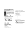
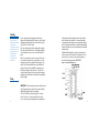
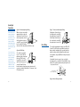
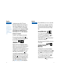
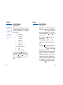
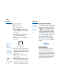
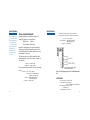
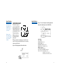
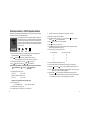
SERIES
SERIES
1X8T/189/1295/25
TEMPERATURE/PROCESS
TEMPERATURE/PROCESS
CONTROLLER
CONTROLLER
Instruction Manual
Instruction Manual
Quick Setup Instructions - 18/19/25 Temperature Controller
Experienced users, already familiar with mounting and wiring the Series 18/19/25 may use these condensed
instructions to autotune the controller and get started quickly.
These quick setup instructions are not meant as a substitute for reading the full
instruction manual. Please be sure to read through the manual for specific details
of operation and, most importantly, for safety precautions. If you have questions,
or experience problems with setting up your controller, consult the full instruction
manual first and, if you still need assistance, contact your Athena representative or
call 1-800-782-6776.
Access
Raise
Lower
Mode
1.
Apply power. After self-check display stops, immediately place the controller into Standby mode by
pressing and holding the
key for four seconds until [ StbY ] flashes.
2.
Press
key until [Ac.Cd. ] flashes. (This can take anywhere from one to eleven
seconds, depending on the menu level at which the controller is currently set.)
3.
If the controller is not at menu level “05”, press
4.
Press
until [ SnSr ] flashes. Then use
or
or
until “05” appears.
to select Sensor Type.
NOTE: Unless otherwise instructed, the following steps require that you first press the Parameter/Access
key, and then the Raise
or Lower
key to select the appropriate
parameter value.
5.
Select Heating Mode on Output 1 [ OUt 1 ].
[ Ht.P ] = PID
[ Ht.O ] = On/Off
Repeat for Cooling Mode on Output 2 [OUt 2 ].
[ CL.P ] = PID
[ CL.O ] = On/Off
Important: If only one output is PID, set the other output to On/Off.
6.
Select Cooling Type [ CoL.t ].
[ nor ] = standard/no cooling
7.
Select Alarm [ AI.H.L.], either [ HI ] or [ Lo ].
8.
Select Alarm Type [ A1.P.d. ], either Process [ Pr ] or Deviation [ dE ].
[ H2o ] = water-cooled extruders
9.
Select Alarm Operation [ Al.O.P.], either Normal [ nor ], Latching [ LAt ] or Off [ OFF ].
10. Repeat Steps 7 through 9 for Alarm 2, if applicable.
11. Select Temperature Units [ Unlt ], either [ F ] or [ C ], then press Mode
point. Use
or
keys to select Setpoint Value.
12. Press
key once to return controller to [ Ac.Cd ] display.
13. Press
key twice to select menu level “03”.
key once to display set-
14. Select Alarm Trip Points [ ALr1 ] and/or [ ALr2 ], if applicable. Note: This menu parameter will not
appear if Alarm Operation (Step #9) is set to [ OFF ].
15. Select Cycle Times [ CY.t1 ] and/or [ CY.t2 ] as follows:
For Control Output Type —
Select Cycle Time (in seconds)
B
E
F
S
T
15
00
00
00
15
16. Scroll to Setpoint Target Time [ SP.tt ] and set to [ OFF ].
17. Select Lower Setpoint Limit [ L.SP.L ] and Upper Setpoint Limit [ U.SP.L ] to the desired value.
18. Press Mode
19. Use the
key once, then
key once to restore [ Ac.Cd ] display. Change to menu level “02”.
key to scroll through to the Damping menu parameter [ dPnG ]. Select normal [ nL ]. Note:
If your process is subject to thermal lag, (see page 28)
20. Press and hold the
key until [ tUnE ] appears. When the display stops flashing [ tUnE ], the
controller is tuned. For safety and security purposes, you may want to change to key-lockout menu level
“00” or Limited Access Run menu level “01” before beginning your process operations.
Safety
Warning
Congratulations on your purchase of an Athena Series 18, 19,
or 25 Single-Loop Controller. It is designed for ease of use
and reliability wherever accurate closed-loop control
is required. Your controller has been configured according to
your ordering specifications as either a universal process
controller or a dedicated temperature controller. In addition,
special functions such as a heater break alarm, digital
communications, etc., have been installed at the factory
and do not require you to make any internal jumper or DIP
switch settings.
In addition to presenting a potential fire hazard, high voltage
and high temperature can damage equipment and cause
severe injury or death. When installing or using this instrument, follow all instructions carefully and use approved
safety controls. Electrical connections and wiring should be
performed only by suitably trained personnel.
Do not locate this instrument where it is subject to excessive
shock, vibration, dirt, moisture, oil or other liquids.
Safe ambient operating temperature range is 32° to 131° F
(0° to 55° C).
After following the instructions for installation, simply step
through and set your desired parameters using the controller’s easy menu system. The instrument may then be automatically or manually tuned to your process for optimum setpoint control. A Quick-Start Reference Card is attached to the
back of the instruction manual for experienced users of PID
controllers. If you still have questions or require any assistance in setting up or operating your controller, please contact
your Athena representative or call 1-800-782-6776.
Precautions
After unpacking, inspect the instrument for any physical
damage that may have occurred in shipping. Save all packing
materials and report any damage to the carrier immediately.
©Copyright 1999, Athena Controls, Inc.
2
3
Table of
Contents
Table of Contents
Installation
6
Mounting
Wiring
8
8
Operation
Notes on Outputs
Front Panel Controls
Parameter Menu Organization
Sensor Configuration
Available Alarms
Parameter Descriptions
Tuning Procedures
Special Functions
Auto/Manual (Standard)
Remote Setpoint Select
Process Variable Retransmission
Heater Break Alarm
Transducer Excitation
4
12
12
14
15
20
22
23
29
Limit Controller Option
Digital Communications
Recalibration Procedure
Error Codes
Warranty/Repair Information
Technical Specifications
Ordering Codes
44
50
58
59
60
62
65
35
35
35
38
40
42
5
Installation
Measurements between
centerlines of panel
cutouts are minimum
recommended.
Installation
Figure 1. Recommended Panel Layout for Multiple Controllers
CL
4.700"
(119.4 mm)
Recommended Panel Cutout
3.622" SQ (92 mm SQ)
CL
Series
25
Figure 2. Case Dimensions
Prior to mounting the controller in your panel, make sure that
the cutout opening is of the right size, and deburred to enable
a smooth fit. A minimum of 4" (100 mm) of depth behind the
panel is required.
CL
4.300" (109.2mm)
CL
C
L
2.850"
(72.4 mm)
Recommended Panel Cutout
3.622" x 1.772"
(92 mm x 45 mm)
CL
CL
CL
2.850"
(72.4 mm)
Figure 3. Series 18/19/25 Controller Mechanical Components (Series 25 shown)
4.300" (109.2mm)
C
L
CL
BEZEL
PANEL
4.300" (109.2mm)
GRIP
Series 18
6
C
L
CL
Series 19
Note: Measurements between centerlines of panel cutouts are minimum recommended.
CASE GASKET
MOUNTING CATCH
7
Mounting
If the unit has been
shipped with mounting
catches already
installed in the top and
bottom slots in the case
housing, they must be
removed to allow
insertion of the
controller into the
panel cutout.
Wiring
Remove static-protective wrapping material from the
instrument. Avoid inducing static charges to controller while
handling and mounting. Insert the controller into the panel
cutout from the front of the panel.
Place the mounting catches into the appropriate mounting
slots at the top and bottom of the case housing and tighten
the mounting screws to secure the controller firmly to the
panel.
Note: For some panels, it may be necessary to first remove
the controller chassis from the case housing to access the
mounting catches from the inside. Press the grips on each
side of the bezel firmly until the tabs release and slide the
chassis out of the housing. Install the housing and secure
it with the mounting screws to the panel. To re-insert the
controller chassis back into its case, press both bezel grips
simultaneously and slide the controller into the housing until
the tabs engage.
kept separate and input leads should never be placed in the
same conduit as power leads. We recommend separating
connecting wires into bundles: power, signal, alarms and outputs. These bundles should then be routed through individual
conduits. Shielded sensor cables should always be terminated
at panel ground.
If additional RFI attenuation is required, noise suppression
devices such as an R.C. snubber at the external noise source
may be used. If you wish, you may order this suppressor
directly from Athena, part number 235Z005U01.
Figure 4. Contact Identification
IMPORTANT: All electrical wiring connections should be made
only by trained personnel, and in strict accordance with the
National Electrical Code and local regulations.
The Series 18/19/25 controllers have built-in circuitry to
reduce the effects of electrical noise (RFI) from various
sources. However, power and signal wires should always be
8
9
SensorInput
Connections
Thermocouple circuit
resistance should not
exceed 100 ohms for
rated accuracy; errors
will occur at higher
resistance values. If
shielded thermocouple
wire is used, terminate
the shield only at panel
ground.
Use wire with a resistance no greater than
10 ohms. An error of
0.2° F will result for
each additional 10
ohms of resistance
encountered. If shielded RTD wire is used,
terminate the shield
only at panel ground.
Figure 5. Thermocouple Input Wiring
Make sure that you are using the
appropriate thermocouple and
extension wire. Connect the negative lead (generally colored red
in ISA-type thermocouples) to
contact #19; connect the positive
lead to contact #20. Extension
wires must be the same polarity as the thermocouple.
Figure 6. RTD Wiring
The controller accepts input
from 2- or 3-wire, 100 ohm
platinum resistance temperature
detectors (RTDs). Connect
2-wire RTDs to contacts #19
and #20, with a jumper across
contacts #18 and #19. Keep
leads short and use heavy gauge copper extension wire, if
necessary, to minimize lead resistance. For long runs, 3-wire
RTDs should be used.
Figure 7. Process and Linear Input Wiring
Voltage Inputs: Connect the positive voltage input to contact #20;
the negative input to contact #19.
Current Inputs: Connect the positive current input to contact #20;
the negative input to contact #19.
Power Wiring
The controller's standard power supply accepts 100 to 250
Vac and 130 to 330 Vdc line power without any switch settings or polarity considerations. All connections should be
made in accordance with the National Electrical Code and
local regulations, using only NEC Class 1 wiring for all power
terminals.
It is advisable, but not necessary, to fuse one leg of the
incoming power line, contact #9 or #10, with a 2AG, 0.5 amp
rated fuse. Be sure that only instrument power input is fused
— not power to the load.
100 - 250 Vac 50/60 HZ
130 - 330 Vdc (Auto Polarity)
Figure 8. Power Wiring Connection
10
11
Operation
Throughout this
manual, instructions
that pertain solely to
the process controller, as opposed
to the temperature
controller, are shown
in blue.
Athena Series 18/19/25 Universal Controller
Output Type
The Series 18/19/25 controller is an autotuning PID controller,
which can function as either a temperature or linear process
controller. (See pages 62-65 for specifications and ordering
code).
B
5A/3A (120/240 Vac) relay, normally
open, used for switching resistive loads. If
relays or solenoids are to be driven, select
the “T” output.
Just a few steps are required before the instrument can be
placed into service. After completing the mounting and wiring
procedures as previously instructed, set your individual
process parameter values by stepping through the setup
menus, using the simple front-panel keys as instructed. Then,
initiate the autotuning sequence as shown (or tune manually).
E
0-20 mA
F
4-20 mA, full output to load with 500 ohm
impedance max. (suppressed).
S
20 Vdc pulsed output for solid-state relays.
T
1 A @ 120/240 Vac , solid-state relay, zero
voltage-switched and optically isolated from
drive signal. Only resistive loads to 1A
may be controlled directly. Larger loads
may be controlled using an external
contactor.
Notes on Outputs
When you ordered your controller, a specific output type was
specified, designated as either “B”, “E”, “F”, “S”, or “T” . You
also had the option of configuring your controller with either
one or two output actions. Generally, output 1 is a heat
(reverse-acting) function and output 2 is a cool (direct-acting)
function. For best results, follow the recommendations for
setting cycle times for the output type supplied with your
controller (see page 26). A brief description of output
types follows:
12
Description
13
Operation
Operation
Figure 9. Front Panel Controls and Indicators
Output 1
LED indication
of Heat cycle
(Output 1 action)
Output 2
LED indication
of Cool cycle
(Output 2 action)
Alarm 1
LED indication
of Alarm1 condition
Alarm 2
LED indication
of Alarm 2 condition
Function 1
LED indication of
Special Function 1
Function 2
LED indication of
Special Function 2
After mounting and wiring your
controller, you are ready to set
the parameter values required
of your application. Take a
moment to familiarize yourself
with the unit’s front panel controls and indicators.
14
Process Value
Displays measured
process temperature
in °F or °C or process
value in engineering
units
Setpoint Value
Displays programmed
setpoint temperature
in °F or °C or setpoint
value in engineering
units
Mode Key Used to access Standby,
Tune, Run or Manual modes.
Lower Key Used to scroll down through
available parameter settings, decrease values
or change menu levels (Hold for fast-step
progression)
Raise Key Used to scroll up through available
parameter settings, increase values or change menu
levels (Hold for fast-step progression)
Parameter/Access Key Used to index through parameters
or to access Menu Levels
Power On
When power is first applied to the controller, both displays
and all LED indicators are momentarily illuminated. The
Process Value (PV) window then displays [ -At- ] or [ -Ap- ]
and the Setpoint Value (SV) window displays an initialization
code, e.g., [ tf05 ]. The last two digits of this code indicate the
software revision supplied with your controller. Please provide this revision number when contacting us regarding your
controller. Depending upon whether Setpoint Target Time
[ SP.tt ] is enabled, you may also see this symbol:
or
. This means that the controller is ramping
up or down to setpoint according to its previously programmed parameters. The default setpoint on initial power up
is equal to the process temperature (process value). Before
proceeding
further, wait until the display has stabilized and then use the
Raise
or Lower
keys to enter or adjust your
desired Setpoint Value.
Parameter Menu Organization
The controller has five distinct menu levels. This enables
quick access to relevant parameters without the need for
15
Operation
You cannot enter
Standby Mode from
menu level “00”. Follow the instructions for
changing menu
levels to select another
level.
Operation
scrolling through long menus. Menu “05” is used for
initial controller configuration and menus “02” and “03” are
used for setting or changing parameters. Menus “00” and
“01” are used when the controller is in regular unattended
operation and are not used for setting parameters. For safety
and security purposes, we recommend placing the controller in menu level “00” or “01” when in regular operation; however, it is not required.
If you wish to “escape” from parameter selection within
these menus at any time, simply press the Mode
key
once. A description of the menu hierarchy and a detailed listing of menus and parameters begins on page 18.
Standby Mode
When the controller is placed in Standby Mode, outputs are
disabled; however, access is permitted to all menu levels and,
unless the controller is at Run menu levels “00” or “01”,
operating parameters may still be changed. This mode is used
for tuning the controller or entering Manual Mode. To enter
Standby Mode, press and hold the Mode key
for four
seconds until the lower window display flashes [ StbY ]. To
exit Standby Mode from Menu Levels “01” to “05”, press and
hold the Mode
key for four seconds until the lower window display flashes [ tUnE ]. (If the Damping setting in menu
“02” is [ OFF ], then Manual Mode will be activated and
[ HEAt ] [ OUt1 ] or [ Cool ] [ OUt2 ] will be displayed with
16
Press and hold the Mode key for four more seconds until the
lower window returns to a steady display of Setpoint Value.
(This procedure will not affect tuning). Removing power to
the controller will also take the instrument out of Standby
Mode.
Accessing Menu Levels
To access menu levels from Standby Mode from menu
levels “02” to “05”, press the Parameter/Access
key
once. From menu levels “00” and “01”, press
and hold the Parameter/Access
key for approximately 4
seconds until the lower window
display alternates between [ Ac.Cd ] and the menu level number last activated.
Changing or Displaying
Menu Levels
To change menu levels, access the menu level display as
instructed in the previous paragraph, then use the Raise
or Lower
key to set the desired menu level number. To
display the current menu level setting in menu levels “02” to
“05”, from Standby press the Parameter/Access
key
once. For menu levels “00” and “01”, press and
hold the Parameter/Access
key for approximately 4 seconds.
17
Operation
Operation
Menu Level Descriptions
Because the controller’s
initial configuration
affects other menu
levels, it is important
to set all required parameters in this menu first
before accessing other
menu levels.
Menu “05” (Configuration Setup)
This is the menu level used for specifying initial configuration
parameters before the controller is placed in Run mode.
After changing the access code to “05” as instructed in the
previous paragraph, press the Parameter/Access
key to
step through the various control parameters.
Available parameters will flash in the lower window display,
alternating with the current value for that parameter, each
time the
key is pressed. To increase or decrease the
value, simply press the appropriate Raise
or Lower
key, then press the
key to step to the
next parameter. To exit the menu at
any time, press the Mode
key. Note: When programming in menu level “05”, all outputs are disabled; however,
any active alarms will remain active until the alarm condition
is removed. New alarm conditions will not be recognized.
Menu “04” (Communications and Calibration Setup)
This menu is used to set up the controller for digital
communications and for recalibrating the controller when
changing from thermocouple to RTD input, or vice versa. If
your controller was ordered with the digital communications
option, set these parameters next. To access this menu level,
follow the instructions previously given.
18
Menu “03” (Alarm, Timing and Limit Setup)
In this menu, alarms, cycle times, setpoint target time and
limits are established. After changing the access code to “03”,
press the Parameter/Access
key to step through the various parameters. To set or
change parameter values, follow the instructions given previously.
Menu “02” (Control Mode)
Gain, Rate and Reset parameters are automatically set during
autotuning. However, they can be manually adjusted by the
operator. To return the controller to the Run mode, change
the menu level access code back to “00” or “01” as previously shown.
Menu “01” (Run — Limited Access Mode)
The only parameter that can be changed at this menu level is
the Setpoint Value, using the appropriate Raise
or Lower
key. To set or change other parameters, the operator
must access another menu level by pressing and holding the
Parameter/Access
key for 4 seconds.
Menu “00” (Run — Key Lock Mode)
In this menu, both display windows are illuminated; however,
access is denied to all parameters. To set or change parameters, the operator must access another menu level as
instructed previously.
19
Operation
The controller may be
configured for various
temperature ranges or
process inputs, but the
unit MUSTbe returned
to the factory to change
function from a temperature controller to a
process controller, or
vice versa.
Operation
Sensor Configuration
Input Configuration
Temperature Controller
With the controller set to configuration menu level “05”, press
the Parameter/Access
key once. The lower display window will alternately flash [ SnSr ] and a code representing the
input type, as follows:
Process Controller
With the controller set to configuration menu level “05”, press
the Parameter/Access
key once. The lower display window will alternately flash [Sn.00 ]
and a code representing suppressed [ SU ] or unsuppressed [
U.SU ]. Use the appropriate Raise
or Lower
key to
select your preference.
c.A
K thermocouple
J
J thermocouple
t
T thermocouple
n
N thermocouple
r
R thermocouple
S
S thermocouple
PLII
Platinel II thermocouple
P
RTD
d
RTD (decimal range)
Press the Parameter/Access
key until [ UnIt ] is displayed and select either Fahrenheit or Celsius using the
appropriate Raise
or Lower
key to toggle between
them. Press the Mode
key to return to the setpoint
display.
20
Press the Parameter/Access
key until [ FILt ] is displayed and select your
desired digital filtering constant (0.1 sec, 1.0 sec, 10 sec),
using the Raise or Lower keys to scroll through the selections.
Press the Mode
key once and then the Parameter/Access
key to return to the menu access
level and use the Lower key
to
change to menu level “03”. Press the
Parameter/Access key again until Low Scale Setting [ L.SCL ]
flashes. Select the desired low scale setting, from -1999 to
9999, using the appropriate Raise or Lower key. Press the
Parameter/Access key again until the High Scale Setting
[ H.SCL ] flashes. Select the desired desired full scale setting,
from -1999 to 9999, using the appropriate Raise or Lower
key. Press the Mode
key to return to the setpoint display.
21
Parameter
Descriptions
Operation
Available Alarm Types [ A1.P.d. ] [ A2.P.d. ]
Figure 11. Temperature Controller Menu Hierarchy
Selectable at menu level “05”, as either Process [ Pr ] or Deviation [ dE ] and either high or low [ A1.HL ] or [ A2.HL ].
Process Alarm: Activates at preset value independent of
setpoint. “High” process alarm activates at and above alarm
setting. “Low” process alarm activates at and below alarm
setting.
Deviation Alarm: Activates at a preset deviation value from
setpoint. “High” or “Low” deviation alarm activates above or
below setpoint according to the preset deviation value.
When a latching alarm
has been activated and
the alarm condition
has been removed, the
Mode
key must
be pressed to unlatch
the alarm.
Latching Alarms
The alarms may also be configured as latching alarms by
selecting “LAt” in the [ A1.O.P.] or [ A2.O.P.] parameter selection at menu level “05”.
With the Heater Break
Alarm option, [L.SP.L]
changes to Heater Current Reading
[ Ht.rd ] (indication
only) and [U.SP.L]
changes to Heater
Break Alarm Setpoint
[ Ht.SP] (either
00-30 Aor 00-60 A).
= temperature
controller only
= process
controller only
Note: Limit Controller Menu Hierarchy
appears on page 44.
= temperature and
process controller
22
23
Parameter
Descriptions
Parameter
Descriptions
Series 18/19/25 Temperature/Process Controller
Menu “05”
Display
SnSr
The Digital Filtering
setting [ FILt ] on the
process controller
allows the operator to
compensate for noise
which may cause the
last digits of the PV
display to become
unstable. Sampling
rate is not affected.
The settings are time
constants, in seconds,
with 0.1 equivalent to
“no filtering.”
24
Parameter
Sensor type
OUt1
Output 1 action
OUt2
Output 2 action
Sn.00
Input Zero Level
dEC.P
FILt
OUt1
Decimal Point
Digital Filtering
Output 1 action
OUt2
Output 2 action
Selection
Thermocouple:
K
J
N
R
T
S
RTD
RTD (decimal range)
Platinel II (special)
Heat PID
Heat On/Off
Cool PID
Cool On/Off
0-20 mA
4-20 mA
PID
On/Off
PID
On/Off
Code
c.A
J
n
r
t
S
P
d
Pl
Ht.P
Ht.O
CL.P
CL.O
U.SU (Unsuppressed)
SU (Suppressed)
999, 99.9, 9.99
0.1, 1, 10
Pid
On.F
Pid
ON.F
CoL.t*
Cooling type
A1.H.L. Alarm 1 select
A1.P.d.
Alarm 1 type
A1.O.P. Alarm 1 output
A2.H.L. Alarm 2 select
A2.P.d.
Alarm 2 type
A2.O.P. Alarm 2 output
Unlt
Measurement units
Water
Normal
Low/High
Process/Deviation
Off/Normal/Latching
Low/High
Process/Deviation
Off/Normal/Latching
°F or °C
H2o (non-linear output)
nor (linear output)
Lo/HI
Pr/dE
OFF/nor/LAt
Lo/HI
Pr/dE
OFF/nor/LAt
F/C
* For water-cooled extruders, select H2o.
Menu “04”
Display
Id.no
bAUd
CAL.L
CAL.H
Parameter
Device ID number
(remote communications)
Baud, parity and
data bit selection
Calibration low
Calibration high
Allowable Values
00 to 99
See chart below
Preset at factory
Preset at factory
Available Communications Settings
Display
3.o.7
6.o.7
12.o.7
24.o.7
3.n.8
6.n.8
12.n.8
24.n.8
Baud Rate
300
600
1200
2400
300
600
1200
2400
Description
Parity
Data Bits
odd
7
odd
7
odd
7
odd
7
none
8
none
8
none
8
none
8
Stop Bits
2
2
2
2
1
1
1
1
25
Parameter
Descriptions
Setting output cycle
time to “00” initiates
a 200 ms timebase. A
cycle time setting is
required for smooth
proportional action.
Too long a setting may
cause proportional
ripple; too short may
decrease relay contactor life.
When changing
thermocouple types,
be sure to check/adjust
upper and lower setpoint limit values.
Parameter
Descriptions
Menu “03”
Display
ALr1
ALr2
Parameter
Allowable Values
Alarm 1 setting
Dependent on sensor range
Alarm 2 setting
Dependent on sensor range
(if ordered)
CY.t1
Cycle time output 1
00 to 120 seconds
CY.t2
Cycle time output 2
00 to 120 seconds
SP.tt
Setpoint target time
Off/1 to 100 minutes
(ramp-to-setpoint)
L.SP.L
Lower setpoint limit
Dependent on sensor range
U.SP.L
Upper setpoint limit
Dependent on sensor range
L.SCL
Low scale setting
-1999 to 9999
H.SCL
High scale setting
-1999 to 9999
Output Type
Recommended Setting (seconds)
B (5A/3A)
15 to 120
E (0-20 mA)
00
F (4-20 mA)
“00”
S (pulsed 20 Vdc) 00 to 120
T (S.S. relay)
15 to 120*
*Note: Shorter cycle times may be used
when driving heater loads directly.
Notes on Setpoint Target Time: The [ SP.tt ] parameter allows the operator to enter a time delay for the
process to reach setpoint temperature (ramp to setpoint), from disabled [ OFF ] or 1 to 100 minutes. When
enabled, the ramp sequence starts on power-up. The ramp-to-setpoint feature will also be initiated whenever
a new setpoint target time is entered AND the Setpoint Value is 5° F or more from the current process temperature. In operation, the controller’s lower window display will flash
or
to indicate that it is
“ramping” up or down to setpoint. The Setpoint Value cannot be
changed during this procedure. After it is finished, the operator can adjust the setpoint temperature to the
desired value.
While in ramp startup, the ramp-to-setpoint mode can be aborted and the controller returned to regular
operation by pressing the Parameter/Access
key until parameters are displayed and then pressing the
26
Setting Rate (Derivative)
or Reset (Integral) to
[ 00 ] disables that
aspect of PID control.
The ratio of rate-to-reset
is limited to a minimum
of 1:4, i.e., Reset value
cannot be set any lower
than four times Rate.
The parameters of Heat
Hysteresis, Cool Hysteresis and Cool Spread
are only available when
Output 1 and/or Output
2 are set to on/off mode
[Ht.O] or [CL.O]. They
replace Gain Output 1
and
Gain Ratio Output 2,
respectively.
Menu “02”
Display
Gn.o1
Gr.o2
H.HYS
C.HYS
HYS1
HYS2
SPr.2
C.SPr
rAtE
rSEt
dPnG
Parameter
Gain Output 1
(PID heat gain)
Gain Ratio Output 2
(PID cool gain ratio)
Heat Hysteresis
Cool Hysteresis
Output 1 Hysteresis
Output 2 Hysteresis
Spread Adjustment, Output 2
Cool Spread
PID rate
PID reset
Damping (see notes)
Allowable Values
00 to 400 (This value may
exceed 400 as
a result of auto-
0.0 to 2.0 tuning.)
01 to 100°
01 to 100°
1 to 100 units
1 to 100 units
0 to 100 units
0 to 100°
00 to 900 seconds
00 to 3600 seconds
Lo, nL, Hi, Off
Notes on Damping: The damping parameter is an autotune feature that
enables more precise control of setpoint overshoot during recovery from
process upsets in which thermal or transfer lag is a factor. See Figure 12.
Use the correct setting prior to autotuning to compensate for power and
load/sensor coupling characteristics.
Lo = Fast recovery with slight overshoot. For single-lag processes.
Ex. Adequate power and excellent load/sensor coupling.
nL = Normal recovery with no overshoot. For two-lag processes.
Ex. Properly sized heaters or components and good load/sensor
coupling.
Hi = Slow recovery with no overshoot. For three-lag processes.
Ex. Overpowered with multiple lags. Poor load/sensor
coupling.
OFF = Autotune disabled; manual output control enabled.
27
Parameter
Descriptions
Tuning
Procedures
Figure 12. Typical Lag Processes
Dead
Time
For best results in tuning the temperature
controller, the setpoint
value should be at least
100°F above or below
ambient temperature.
While some processes
other than heat or cool
applications may
respond successfully to
autotuning procedures,
the controller must be
manually tuned for
most non-temperature
processes.
The Series 18/19/25 is an “on demand” autotuning controller
that automatically sets PID parameter values (Proportional
Band, Reset and Rate) before the process reaches setpoint. A
damping setting (menu level “02”) MUST be selected for autotuning to take place. (see Notes on Damping, page 27). The
controller may also be tuned manually (see page 32).
Autotuning the Temperature Controller
1) With the power off and the process at ambient, apply
power and immediately put the controller in Standby mode
by holding the
key for four seconds until [ StbY ]
flashes in the lower display window. If controller is in
menu level “00” or “01”, hold the Parameter/ Access
key for 11 seconds until [ Ac.Cd ] appears. Then
change to menu level “05”.
2) Press the
key once and use the
menu level “05”.
key to select
3) Enter the desired Setpoint Value using the appropriate
Raise
or Lower
key. [ StbY ] will continue to
flash.
4) Press the Parameter/Access
key twice until [ SnSr ]
is displayed to make sure
that the proper sensor has been selected. Then set the
controller’s heating mode by pressing the
Parameter/Access
key again until [ OUt1 ] is dis-
28
29
Tuning
Procedures
Tuning
Procedures
played. (If you scroll past it, just continue scrolling until the
parameter menu repeats.) Using the appropriate Raise
or Lower
key, select the one of the following
settings according to the requirements of your process.
Note: For autotuning, at least one output MUST be set
to PID mode.
Mode
PID
On/Off
Output 1 (Heat) Setting
[ Ht.P ]
[ Ht.O ]
Output 2 (Cool) Setting
[ CL.P ]
[ CL.O ]
Press the Parameter/Access
key again to step to output
2 [ OUt2 ]. Repeat the selection process for cooling mode.
If only one output is PID, set the other output to On/Off.
5) Press the Parameter/Access
key again to display the
Cooling Type parameter [
CoL.t ], and select either Normal/Linear output [ nor ] or
Water-Cooled/Non-Linear output [ H2o ].
6) Exit menu level “05” by pressing the Mode
key once.
The lower window will flash [StbY]. Now press the Parameter/Access
key once. The lower window will
display [Ac.Cd ] and [ 05 ]. Press the Lower
key twice
to select menu level “03”.
30
7) Press the Parameter/Access
key and select Cycle Time
for Output 1 [ CY.t1 ] and
Cycle Time for Output 2 [ CY.t2 ]. For Control Output type B
Before autotuning can
take place, you must
select a damping setting. If the damping
parameter does not
appear on the menu,
you have not selected a
PID option for outputs
1 or 2. Refer back to
step (4) and select the
proper setting(s).
During autotuning, the
process temperature
will gradually cycle
from ambient to setpoint. When autotuning
is complete, the [ tUnE ]
display will stop flashing and the Gain, Rate
and Reset numbers
"learned" will be kept in
memory for subsequent
startups.
or T, enter “15”. For Control Output type E, F or S, enter
“00”.
8) Press the Parameter/Access key until Setpoint Target Time
[ SP.tt ] is displayed. Select [ OFF ].
9) Press the Mode
key once. The lower window will again
flash [StbY]. Press the Parameter/Access
key once and
the lower window will display [Ac.Cd ]
and [ 03 ]. Press the Lower
key once to select menu
level “02”.
10) Press the Parameter/Access
key and scroll through
the displayed parameters. If
Gain Ratio [ Gr.o2 ] is displayed, set it to [ 1.0 ]. Otherwise,
continue scrolling until [dPnG ] appears. Set Damping initially to Normal [ nL ]. (This setting may have to be changed
later. See Notes on Damping, page 28).
11) Press and hold the Mode
key until [ tUnE ] flashes
in the lower display window. The controller is now autotuning. When it stops flashing, the autotuning procedure is
completed and the controller is ready for your process.
As a security measure, you may wish to place the controller
in Key Lock “00” or Limited Access “01” Run mode by
changing menu levels as instructed previously.
Autotuning will not function when process is at setpoint.
Figure 13. Typical “Autotune” Temperature Profile.
31
Tuning
Procedures
If overcooling exists on
heat/cool processes
after autotuning,
decrease Gain Ratio
[ Gr.o2 ] in steps of 0.1
until oscillation is
minimal. If cooling is
sluggish, increase the
value in steps of 0.1
until optimum results
are achieved.
Tuning
Procedures
Manual Tuning Procedure - Temperature
Controller (Zeigler-Nichols PID Method)
This tuning method may be used if the spread between ambient temperature and process operating temperature is small.
For best results, the use of a recording device is suggested
when tuning with this method.
1) Disable any cooling device used.
2) Apply power and place the controller in Standby by
pressing and holding the Mode
key for four seconds.
3) Access menu level “02” following instructions given
previously.
4) Using Raise
desired value.
or Lower
key, adjust setpoint to
Gain ratio [ Gr.o2 ] is
the cooling gain
expressed as a factor
of the heating gain.
6) Index to Gain Ratio [ Gr.o2 ] and select [ 1.0 ].
Ex. [ Gn.01 ] = 100
[ Gr.o2 ] = .5
Cooling Gain = 50
8) Index to Reset [ rSEt ] and select [ 00 ]. Note: In order to
set Reset to [ 00 ] , Rate must first be set to [ 00 ].
5) Using the Parameter/Access
[ Gn.o1 ]. Select [ 01 ].
Calculate and enter these
numbers:
Rate [rAtE] = T/8
Reset [rSEt] = rate x 4
Gain [Gn.01] = Step (15) x 0.6
key, index to Heat Gain
7) Index to Rate [ rAtE ] and select [ 00 ].
9) Change to menu level “03”.
32
10) Index to Cycle Time 1 [ CY.t1 ] and select the timebase,
in seconds, appropriate to the device being controlled.
(See note on page 27.)
33
Tuning
Procedures
Special Functions
11) Repeat for Cycle Time 2 [ CY.t2 ].
12) Change to menu level “05”.
13) Set Cooling Type [ CoL.t ] to [ nor ].
14) Press the Mode
key once. Setpoint Value will be
displayed. The recording device should now be tracking
process temperature.
15) Double the Gain [ Gn.o1 ] until a small, sustained oscillation is visible on the recording device’s trace.
16) Measure the period of one cycle of oscillation (“T” on the
diagram below).
T
Calculate and enter these
numbers:
Rate [ rAtE ] = T/8
Reset [ rSEt ] = T/2.0
Gain [ Gn.01 ] = Gain from
Step (8)
On noisy processes,
where Rate cannot be used:
Gain [ Gn.01 ] = from Step
(8) x 0.45
Reset [ rSEt ] = T/1.2
T
34
Auto/Manual Operation (Standard)
In manual control
mode, error conditions
such as A/D errors
and open or reversed
sensors will be
ignored.
To put the controller in manual mode, set the damping [dPnG]
parameter in menu level “02” to [ OFF ]. Press and hold the
Mode
key for four seconds until the lower display window flashes [ StbY ]. Hold down the Mode key for another
four seconds to initiate manual operation. The lower display
window will flash PID output as a percentage of output power,
from 100 to -100, alternating with the output controlled (temperature controllers will flash [ HEAt ] or [ CooL], process
controllers will flash [ OUt1 ] or [OUt2 ].) To take the controller out of manual mode, press and hold Mode
key to
four seconds.
Remote Setpoint Option
17) Divide the period of oscillation (T) by eight (8). The resulting number is the correct Rate time [ rAtE ] in seconds.
Multiply this number by four. This is the correct Reset time
[ rSEt ] in seconds.
18) Multiply the gain (from step #15) by 0.6 and enter this
number as Gain [ Gn.o1 ].
19) Enable the cooling device. If overcooling exists, decrease
the Gain Ratio [ Gr.o2 ] in steps of 0.1 until temperature
oscillation stops. If cooling is sluggish, increase the Gain
Ratio in steps of 0.1 until optimum results are achieved.
If your controller was ordered with this option, you may
select either of two setpoints for your process. The second
setpoint can be enabled only by an external switch or signal,
according to your ordering specifications. The "F2" LED on the
front panel will illuminate when a second setpoint is selected.
If you do not know how your controller was configured, refer
to the ordering code and description on page 65.
35
Special Functions
Special Functions
When installed, this option provides the user with a method
of inputting several types of analog signals to the controller,
typically 1-5 volts or 4-20 milliamps, although it is also capable of 0-5 volts or 0-20 milliamps in the unsuppressed mode.
The primary purpose of this feature is to provide an auxiliary
analog Second Setpoint function for control of Setpoint Value
by remote computer, analog potentiometer or other source.
The analog input value replaces the primary digital (front
panel keyed-in value) when the switch input associated with
the module is closed. The option also provides a 5 volt
excitation for the remote potentiometer (see wiring diagram).
OPTION ORDERING CODES
Figure 14. Wiring Diagram for Remote Setpoint
Select Option
Remote
voltage/current
Analog setpoint input
Analog remote
setpoint potentiometer
with enable switch
+
0-5v/1-5v
0-5 V/1-5 V
0-20 mA/4-20 mA
0-20ma/4-20ma
ENABLE
SWITCH
10K
CW
1
SA Switch Closed & 0-5 V dc or (500 - 10 Kohm) Potentiometer signal input
SB1
"
"
SC2
"
"
1-5 V dc
0-20 mA dc
SD2
"
"
4-20 mA dc
The above options require an external switch on pins 14 & 15 and a remote
signal on pins 12 & 13, to change to the second setpoint value.
SE Second Setpoint Switch (front panel)
1
2
36
INPUT IMPEDANCE= 20K ohms
INPUT IMPEDANCE = 250 ohms
37
Special Functions
Special Functions
Process Variable Retransmit
These output values
are linear with and
dependent upon the
sensor being used,
i.e., the lowest value
of the sensor’s output range corresponds to zero or
low for the output
function.
Retransmit Signal is the retransmission of the process
variable (PV) signal out to an external device:
*Chart Recorder
*Indicator
*Process Controller *Data Logger
Note: In degrees Celsius mode there will be a shift, as follows:
(The lowest value of the range is the zero output for the output function)
“J” couple = -18 to 760 degrees C
Output -18 degrees C = 0 Vdc/0 mAdc-unsuppressed
= 1 Vdc/4 mAdc-suppressed
760 degrees C = 5 Vdc/20 mAdc
Generally, the main purpose of the retransmit signal is for
keeping a log of data information with respect to time. It is
not a scaleable parameter, but rather a variable process signal, dependent on sensor type.
This option provides the user with the capability to attach
auxiliary equipment, such as chart recorders, computers, etc.
The outputs are:
suppressed— 1-5 Vdc/4-20 mAdc
unsuppressed — 0-5 Vdc/0-20 mAdc
They correspond to the zero and full scale values of the range
selected.
Example: “J” couple = 0 to 1400 degrees F
Output = 0-5 Vdc/0-20 mAdc unsuppressed
= 1-5Vdc/4-20 mAdc suppressed
0 degrees F = 0 Vdc/0 mAdc-unsuppressed
= 1 Vdc/4 mAdc-suppressed
1400 degrees F = 5 Vdc/20 mAdc
38
Note: Voltage out requires a jumper
between terminals 16 & 17
Figure 15. Wiring Diagram for Process Variable Retransmission
SPECIFICATIONS
I out (current output) = 0-20 mA / 4-20 mA
Voltage Headroom = 8 Vdc- standard
= 18 Vdc - for multiple chart recorders optional
V out (voltage output) = 0-5 Vdc / 1-5 Vdc
I out MAX = 20 mA
Output Impedance = 255 ohms max.
39
Special Functions
Special Functions
Figure 17. Current Transformer (Can Be Supplied with
Heater Break Alarm Option, Part # 580E023UOI)
HEATER BREAK ALARM
The Heater Break
Alarm option is not
available on controllers with an “F”
type output.
With the Heater
Break Alarm option,
cycle time is limited
to greater than 2
seconds.
The Controller compares a
sensor input signal with the
Setpoint and makes a power
calculation, which produces
an output signal to the load.
CONTROLLER
The Heater Break Alarm
(HBA) detects failures in
the load and provides an
alarm output.
HBA uses an external current transformer to monitor the load
current. If the load current should fall below a set current value,
an alarm output will activate.
Figure 16. Wiring Diagram for Heater Break Alarm
Standard Option
Ordering Codes
HA
HB
40
Current Range
SPECIFICATIONS
.29" DIA. OPENING
INDICATING RANGE: 2 thru 100 A
MAX.CONT.CURRENT: 100 A
MAX.TRANSIENT CURRENT: 150 A for 5 sec.
WORKING CLASS: 600 • FREQUENCY: 50-60 Hz
WEIGHT: .5 Oz (14 grams)
LEAD WIRE: #22 AWG UL Style 1213
CASE COLOR: Black • CASE MATERIAL: Thermoplastic
Remote Current Transf.: Indicating Range : 2-100 A
Working Class : 600 volts, 50-60 Hz
Max.Transient Current: 150 A for 5 seconds
0 -30A
0 -60A
41
Special Functions
Special Functions
Transducer Excitation
The transducer excitation voltage option is used to produce
a constant dc voltage of 10, 12 or 15 Vdc out to an external
device, eliminating the need for an additional external power
supply. Refer to the ordering code if you do not know which
voltage output was specified.
Option Ordering Code
1
2
3
Figure 18a. Wiring Diagram for 2-Wire Sensor Input with
Transducer Excitation Option
Voltage Output
10 V
12 V
15 V
Maximum Current = 22 mA
MAXIMUM CURRENT = 22 mA
OUTPUTVOLTAGES = 10,12 and 15 Vdc
AMBIENTTEMP
= 32-131° F, 0-55° C
Figure 18. Wiring for Transducer Excitation Output
42
43
Limit Controller
Option ED
Limit Controller
Option ED
Series 18/19/25 Limit Controller Menu Hierarchy
Parameter Descriptions
Menu “04”
Display
IntP
44
Parameter
Sensor type
LItp
Limit type
AltP
ALSL
Alot
oPSL
dECP
FILt
UnIt
Alarm type
Alarm select
Alarm output
Selection
Thermocouple
Platinel II
S
T
R
N
J
K
RTD
RTD (decimal range)
Platinel II (special)
High Limit
Low Limit
Process/Deviation
High/Low Alarm
Normal/Latching
(Not Functional)
(Not Functional)
Decimal point
Digital filtering
Measurement units F-deg or C-deg
Code
PLII
S
t
r
n
J
c.A
P
d
Pl
HI
Lo
Pr/dE
HI/Lo
nor/LAt
00
02/01/00
10.0/1.0/0.1
F/C
45
Limit Controller
Option ED
Limit Controller
Option ED
Parameter Descriptions (continued)
Parameter Descriptions (continued)
Menu “03”
Display
Idno
Menu “02”
Display
ALSP
SPLo
bAUD
CALL
CALH
Parameter
Device ID number
(remote communications)
Baud, parity and
data bit selection
Calibration low
Calibration high
Allowable Values
00 to 99
See next page under the
heading of “Available
Communications Settings”
Preset at factory
Preset at factory
SPHI
Parameter
Alarm setpoint
Setpoint low
(lower setpoint limit)
Setpoint high
(upper setpoint limit)
Allowable Values
0 to 8191
Dependent on sensor range
Dependent on sensor range
Available Communications Settings
Display
24.n.8.
12.n.8.
6.n.8.
3.n.8.
24.o.7.
12.o.7.
6.o.7.
3.o.7.
46
Baud Rate
2400
1200
600
300
2400
1200
600
300
Description
Parity
Data Bits
none
8
none
8
none
8
none
8
odd
7
odd
7
odd
7
odd
7
Stop Bits
1
1
1
1
2
2
2
2
47
Limit Controller
Option ED
Limit Controller
Option ED
Operation
High Limit Operation — During normal operation the
mechanical relay in output “1” is closed. If the process
temperature exceeds the high limit setting, then the
mechanical relay in output “1” will open (“01” LED is
now lit) cutting off power to the load. When the process
temperature drops back down to below the limit setting,
output “1” will remain open until you press the mode key
to reset the controller.
Low Limit Operation — During normal operation the
mechanical relay in output “1” is closed. If the process
temperature drops below the low limit setting, then the
mechanical relay in output “1” will open (“01” LED is
now lit) cutting off power to the load. When the process
temperature rises back above the limit setting, output “1”
will remain open until you press the mode key to reset
the controller.
Mode Key (Reset Button) — Operates as a reset button.
The Parameter Access Key — Used to index through
parameters or to access menu levels.
Raise Key — Used to scroll up through available parameter
settings, increase values or change menu levels (Hold for
fast-step progression).
48
Lower Key — Used to scroll down through available
parameter settings, decrease values or change menu levels
(Hold for fast-step progression).
Operation (continued)
Warning: Do not
change the values in
the CALLor CALH
menu parameters.
If this is done, the
controller may need
to be recalibrated.
Tech Tip: After setting
up your controller,
index through the
entire menu system
and write down the
value or setting of each
menu parameter. Keep
this hard copy on hand
in the event that an
operator accidently
changes the values or
settings. Then you can
refer back to this list of
settings and values to
correctly set up the
controller.
Quick Start Procedure
1) Apply power to the controller.
2) Press parameter access key to access the menu system.
3) Using the up/down arrow keys, select menu level “04”.
4) Press the parameter access key once until you reach the
sensor type (IntP).
5) Select the sensor type that you will be using by pressing
the up/down arrow keys (refer to parameter descriptions
for menu “04” described earlier).
6) Press the parameter access key again to reach the limit
type (LItP).
7) Using the up/down arrows keys, select High or Low limit.
8) Press the mode key to return to limit setting.
9) Set your limit to the desired value by pressing the
up/down arrow keys.
10) To deny controller access through the front panel, press
the parameter access key once, then using the up/down
arrow keys, select menu level “00”. Press the mode key
once. The controller is now in lockout mode. To regain
controller access you must hold the parameter access key
in for 11 seconds.
49
Digital
Communications
Digital
Communications
RS232
Two communication
options are available
which allow interfacing
to remote devices
utilizing the most
common industry
standards, RS232 and
RS485.
WARNING
Signal ground only.
Grounding to frame
may damage the
controller and void
warranty.
50
This method allows bidirectional data transfer via a threeconductor cable consisting of signal ground, receive input
and transmit output. It is recommended for communication
distances less than fifty feet between the computer terminal
and the instrument. Note: Multiple instruments cannot be
connected to the same port.
Note: Call factory for a
recommended RS485
converter.
short as possible; however, the line may be daisy-chained at
each controller. The polarity of the line is important and each
device will specify an “A” (+) and “B” (-) connection.
The RS232 port is optically isolated to eliminate ground loop
problems. Typically, “Data Out” of the computer/terminal connects to the “RCV” terminal. “Data In” connects to the “XMT”
terminal. If shielded cable is used, it should be connected to
the frame ground at one end only. Signal ground is to be connected at appropriate ground terminals (refer to wiring diagram, page 51).
RS485
The RS485 multipoint capability allows up to 32 controllers to
be connected together in a half-duplex network or up to 100
controllers with an appropriate communications repeater. This
method allows bidirectional data transfer over a shielded
twisted pair cable. The twisted pair cable is a transmission
line; therefore, terminating resistors are required at the most
distant ends of the line to minimize reflections (typically 60
ohms from each line to signal ground). The RS485 circuit is
fully optically isolated, eliminating ground loop problems.
Parallel drops from the transmission lines should be kept as
Figure 19. Wiring
diagram for digital
communications.
51
Digital
Communications
Digital
Communications
Table 1. Communications Parameter List
(Temperature Controller)
Parameter No.
00
01
02
03
04
05
06
07
08
09
10
11
12
13
14
15
16
17
18
19
Description
Process Value
Setpoint
Access Code
Gain Output 1
Gain Ratio 2
Rate
Reset
Heat Hysteresis
Cool Hysteresis
Cool Spread
Damping
Alarm 1
Alarm 2
Cycle Time 1
Cycle Time 2
Setpoint Target Time
Low Setpoint Limit
High Setpoint Limit
Controller ID
Baud Rate
Display
nnnn
nnnn
Ac.Cd
Gn.o1
Gr.o2
rAtE
rSEt
H.HYS
C.HYS
C.SPr
dPnG
ALr1
ALr2
CY.t1
CY.t2
Sp.tt
L.SP.L
U.SP.L
Id.no
bAUd
Minimum
Maximum
Sensor Dependent
Low Limit
High Limit
00
05
00
400
0.0
2.0
00
900
00
3600
01
100
01
100
00
100
OFF
High
Range Dependent
Range Dependent
00
120
00
120
00 (OFF)
100
Sensor Dependent
Sensor Dependent
00
99
300
2400
Table 2. Communications Parameter List
(Process Controller)
52
Parameter No.
00
01
02
Description
Process Value
Setpoint
Access Code
Display
nnnn
nnnn
Ac.Cd
Minimum
Low Scale
Low Scale
00
Maximum
High Scale
High Scale
05
03
04
05
06
07
08
09
10
11
12
13
14
15
16
17
18
19
Gain Output 1
Gain Ratio 2
Rate
Reset
Hysteresis 1
Hysteresis 2
Spread 2
Damping
Alarm 1
Alarm 2
Cycle Time 1
Cycle Time 2
Setpoint Target Time
Low Scale
High Scale
Controller ID
Baud Rate
Gn.o1
Gr.o2
rAtE
rSEt
HYS.1
HYS.2
SPr.2
dPnG
ALr1
ALr2
CY.t1
CY.t2
Sp.tt
L.SCL
H.SCL
Id.no
bAUd
00
0.0
00
00
01
01
00
00
Low Scale
Low Scale
00
00
00 (OFF)
-1999
-1999
00
300
400
2.0
900
3600
100
100
100
Low/Normal/High
High Scale
High Scale
120
120
100
9999
9999
99
2400
Table 3. Serial Communications Data Format
Baud
Code
3.o.7
6.o.7
12.o.7
24.o.7
3.n.8
6.n.8
12.n.8
24.n.8
Baud
Rate
300
600
1200
2400
300
600
1200
2400
Parity
Odd
Odd
Odd
Odd
None
None
None
None
Data
Bits
7
7
7
7
8
8
8
8
Stop
Bits
2
2
2
2
1
1
1
1
53
Digital
Communications
Digital
Communications
Figure 20. General Communications Message Format
Interface Examples
This section describes the protocol for communication
between the controller and either a video display terminal or
computer ( referred to below as “the host”). Message strings
may be of two types — commands to controller or responses
from controller.
Caution:
Modifying parameter
#19 (Baud Rate) by
host may cause loss of
data link.
#[controller id] [command] [parameter number]<new value><units> [CR]
OPTIONAL
OPTIONAL
Start of
message
ONE
Character
Upper case
or Lower case
R Read
M Modify
E Enter
General Comments
One host and multiple controllers may be interconnected on a
single bus. The host may send commands to any controller
and may receive responses from any controller. Each controller on the bus is assigned an identification code between
00 and 99. No two controllers on a given bus may have the
same identification code. Controllers are not capable of communicating with other controllers.
Up to TWO
Numeric
Characters
00 to 99
Up to TWO
Numeric
Characters
00 to 99
SPECIAL
COMMANDS
N
ON
(Select)
F
OFF
(Deselect)
?
STATUS
0
1
2
3
9
Up to SIX
Characters
ONE Leading
Sign
‘-’,‘+’or
Space and
FOUR
Numeric
Characters
with decimal
for decimal
parameters
Standby
Autotune
Manual
Ramp
Version
(Status Only)
End of
message
ONE
Character
F Deg F
C Deg C
U PROCESS
SENSOR
None for default
Temperature units
of NON-THERMAL
parameters
Every valid message begins with a pound-sign (#) character.
Every valid message ends with a carriage-return (<CR>)
character.
A valid message is composed of: Start Character, Controller
ID Code, Command, Parameter, Data, Carriage-Return.
Every response begins with a line-feed (<LF>) character and
ends with a carriage-return, line-feed pair (<CRLF>).
54
Example: For Standby “On”, type #01N0[CR].
For proper digital communication with the controller(s), make the
following checks:
• Baud rate of the controller(s) must match that of the computer
or PLC device.
• Controller communication cable is connected to the correct
serial port on your computer or PLC.
• Data TX and RX lines are going to the proper connector pins. If
you are using RS422 line, short the RX+ and TX+ together
(“A” signal) and the RX- and TX- together (“B” signal).
See wiring diagram, page 9.
55
Digital
Communications
Communications
Notes
Figure 21. Sample Communications Commands
STANDBY ‘ON’ COMMAND TO CONTROLLER
STANDBY RESPONSE FROM CONTROLLER
STANDBY
Controller Id
End of
Message
< >
‘#01N0 CR
< >
< >< >
‘ LF #01N0 CR LF ’
Command
Executed
ON (Select)
Command
Start of Message
STANDBY ‘OFF’ COMMAND TO CONTROLLER
STANDBY RESPONSE FROM CONTROLLER
STANDBY
Controller Id
End of
Message
< >
< >
‘#01F0 CR
< >< >
‘ LF #01F0 CR LF ’
Command
Executed
OFF (Deselect)
Command
Start of Message
STANDBY ‘?’ COMMAND TO CONTROLLER
STANDBY RESPONSE FROM CONTROLLER
STANDBY
Controller Id
< >
End of
Message
< >
‘#01?0 CR
Start of Message
< >< >
‘ LF #01F0 CR LF ’
N
Status REQUEST
Command
Standby STATUS
is ‘off’
Standby STATUS
is ‘on’
Figure 22. Requesting a Parameter from a Controller
On "Read Response"
from controller using a
decimal format, syntax
will be as follows:
Msg Sent: '#01R00<CR>'
Msg Received:
'<LF>#01R00 = -183.7F'
SAMPLE: READ, MODIFY, ENTER COMMANDS
READ MESSAGE TO CONTROLLER
Parameter Number
Controller Id
< >
End of
Message
‘#01R00 CR ’
< >< >
Value read from
controller
Read
Command
Start of Message
MODIFY COMMAND TO CONTROLLER
Parameter Number
MODIFY RESPONSE FROM CONTROLLER
Controller Id
Units
Units
< >
56
Units
< >
‘ LF #01R00 = 0120F CR LF ’
< >
‘#01M01 0200F CR ’
On "Modify" or "Enter"
commands, do not use an
equals sign (=); use a
"space" instead.
Ex. '#01M01 0200F<CR>'
READ RESPONSE FROM CONTROLLER
Start of Message
Modify Command
< >< >
‘ LF #01M01 0200F CR LF ’
End of
message
New Value
‘space’ for
Positive
ENTER COMMAND TO CONTROLLER
Parameter Number
Modified Value
ENTER RESPONSE FROM CONTROLLER
Controller Id
Units
Units
< >
‘#01E01 0200F CR ’
Start of Message
Enter Command
New Value
‘space’ for
Positive
< >
< >< >
Caution:
Wherever possible,
avoid using the
“Enter” command
and use “Modify”
instead. The “Enter”
command makes permanent changes to the
NOVRAM in the
microprocessor, and
after accepting a
maximum capacity of
100,000 “Enter” statements, it will have to be
returned to the factory
and replaced.
1. The controller will respond with <LF>ERROR<CR><LF>
for messages containing invalid/incorrect commands,
parameter number or data (with decimal, if needed).
2. Process Value is a read-only parameter; therefore, a modify or enter command for Process Value will result in a
<LF>ERROR<CR><LF> response.
3. For modify or enter command: if the new value is out of
the parameter’s range, the controller will default to the
highest or lowest allowable parameter value.
4. Parameters with decimal data must contain a decimal
character in the data portion of the message.
5. Ramp “on” command (Setpoint Target Time) will not be
executed if ramp time is set to zero or absolute deviation
between Setpoint and Process Value is less than 5
temperature or process units.
6. Autotune, manual and ramp commands are mutually
exclusive, i.e., selecting manual while autotune is enabled
will abort the autotune mode.
7. If the controller is in Standby mode, selecting autotune,
manual or ramp will de-select Standby.
8. Setpoint should not be modified while the controller is in
autotune or ramp mode.
9. The Setpoint Value enter command should not be executed while the controller is in manual mode.
‘ LF #01E01 0200F CR LF ’
End of
message
Entered Value
57
Recalibration
Only qualified individuals utilizing the
appropriate calibration equipment
should attempt
recalibration of
the controller. For
assistance, contact
your Athena representative or call
1-800-782-6776.
Error Codes
Your controller has been calibrated at the factory, and need
not be adjusted during the life of the controller unless sensor
type is changed from thermocouple to RTD, or vice versa. In
the event that recalibration is warranted, follow these
procedures.
1) Access menu level “05” as previously instructed and
select the sensor type.
2) Connect a calibrator with a range appropriate for the unit
to be calibrated. Allow the controller to warm up for a minimum of 20 minutes. Set the range, and a low or zero value.
3) Access menu level “04” and then the Parameter/Access
key until [ CAL.L ] is displayed. Then, press the
Raise
or Lower
key until the number in
the controller’s upper (PV) display window matches the
indicated value of the calibration instrument.
Display
Problem
Action
[ Err.H ]
Open sensor
Check sensor and wiring
Check type of sensor
Recalibrate
[ Err.L ]
Reversed sensor
Check sensor and wiring
Check type of sensor
Recalibrate
[ Err.O ]
A/D error
Return to factory
[ Err.J ]
A/D error
Return to factory
----
Display out-of-range
Sensor over- or under-range
LoAd
no
No control output
Call factory
4) Enter a value on the calibration instrument corresponding
with the high-end value of the sensor range (span).
5) Again, in menu level “04”, press the Parameter/Access
key until [ CAL.H ] is displayed. Then, press the
Raise
or Lower
key until the number in
the controller’s upper (PV) display window matches the
indicated value of the calibration instrument.
6) Repeat steps 3 through 5 until all readings agree.
58
7) Return the controller to regular operation by changing
back to menu level “00” or “01” (if desired) and pressing
the Mode
key.
59
Warranty/Repair
Information
Warranty/Repair
Two-Year Limited Warranty
Other than those expressly stated herein, THERE ARE
NO OTHER WARRANTIES OF ANY KIND, EXPRESS OR IMPLIED,
AND SPECIFICALLY EXCLUDED BUT NOT BY WAY OF LIMITATION,
ARE THE IMPLIED WARRANTIES OF FITNESS FOR A PARTICULAR
PURPOSE AND MERCHANTABILITY.
IT IS UNDERSTOOD AND AGREED THE SELLER’S LIABILITY
WHETHER IN CONTRACT, IN TORT, UNDER ANY WARRANTY, IN
NEGLIGENCE OR OTHERWISE SHALL NOT EXCEED THE RETURN OF
THE AMOUNT OF THE PURCHASE PRICE PAID BY THE PURCHASER
AND UNDER NO CIRCUMSTANCES SHALL SELLER BE LIABLE FOR
SPECIAL, INDIRECT, INCIDENTAL OR CONSEQUENTIAL DAMAGES.
THE PRICE STATED FOR THE EQUIPMENT IS A CONSIDERATION IN
LIMITING SELLER’S LIABILITY. NO ACTION, REGARDLESS OF
FORM, ARISING OUT OF THE TRANSACTIONS OF THIS AGREEMENT
MAY BE BROUGHT BY PURCHASER MORE THAN ONE YEAR AFTER
THE CAUSE OF ACTION HAS ACCRUED.
SELLER’S MAXIMUM LIABILITY SHALL NOT EXCEED AND BUYER’S
REMEDY IS LIMITED TO EITHER (i) REPAIR OR REPLACEMENT OF
THE DEFECTIVE PART OR PRODUCT, OR AT SELLER’S OPTION (ii)
RETURN OF THE PRODUCT AND REFUND OF THE PURCHASE
PRICE, AND SUCH REMEDY SHALL BE BUYER’S ENTIRE AND
EXCLUSIVE REMEDY.
60
Unit Repairs
It is recommended that units requiring service be returned to
an authorized service center. Before a controller is returned
for service, please consult the service center nearest you.
In many cases, the problem can be cleared up over the telephone. When the unit needs to be returned, the service center
will ask for a detailed explanation of problems encountered
and a Purchase Order to cover any charge. This information
should also be put in the box with the unit. This should
expedite return of the unit to you.
This document is based on information available at the time
of its publication. While efforts have been made to render
accuracy to its content, the information contained herein does
not cover all details or variations in hardware, nor does it
provide for every possible contingency in connection with
installation and maintenance. Features may be described
herein which are not present in all hardware. Athena Controls
assumes no obligation of notice to holders of this document
with respect to changes subsequently made.
Proprietary information of Athena Controls, Inc. is furnished
for customer use only. No other use is authorized without the
written permission of Athena Controls, Inc.
61
Technical Specifications
Technical Specifications
Performance
Accuracy
Setpoint Accuracy
Temperature Stability
TC Cold End Tracking
Noise Rejection
Process Sampling Rate
Inputs
Thermocouple
RTD
Linear
±0.2% of full scale, ± one digit
1 degree/0.1 degree
5 µV/°C max; 3 µV/°C typical
0.05° C/°C ambient
Common mode >100 dB
Series Mode >70 dB
10 Hz (100 ms)
K, J, N, R, T, S,
Maximum lead resistance 100 ohms
for rated accuracy
Platinum 2- and 3-wire, 100 ohms at
0° C, DIN curve standard (0.00385)
0-50 mV/10-50 mV, 0-5 V/1-5 V/
0-10 V/2-10 V, 0-20 mA/4-20 mA
Input Impedances
0-50 mV/10-50 mV: >1 M ohm ± 1%
0-5/1-5 V: 12.5 K ohm ± 1%
0-20 mA/4-20 mA: 250 ohm ± 1%
0-10 V/2-10 V: 200 K ohm
62
Outputs
#1
#2
B
E
F
S
T
Alarms
B
T
trol Characteristics
Setpoint Limits
Alarms
Rate
Reset
Cycle Time
Gain
Gain Ratio
Control Hysteresis
Cool Spread, Output 2
Spread 2, Output 2
Reverse acting (heating)
Direct acting (cooling)
Relay, 5 A @ 120 Vac resistive
3 A @ 240 Vac
0-20 mAdc, 500 ohm max.
4-20 mAdc, 500 ohm max.
20 Vdc pulsed
Solid-state relay, 120/240 Vac,
zero voltage-switched,
1 A continuous, 10 A surge @ 25° C
Electromechanical relay, 5 A @ 120 Vac,
3 A @ 240 Vac
Solid-state relay, 120/240 Vac,
zero voltage-switched,
1 A continuous, 10 A surge @ 25° C ConLimited to configured range
Adjustable for high/low; selectable
process or deviation
0 to 900 seconds
0 to 3600 seconds
0.2 (zero setting) to 120 seconds
0 to 400
0 to 2.0 (in 0.1 increments)
1 to 100 units (on/off configuration)
0 to 100° F/C above setpoint (Temp.)
0 to 100 units above setpoint (Process)
63
Technical Specifications
Ordering Codes
Damping
Setpoint Target Time
(Ramp-to-Setpoint)
Autotune
Manual
General
Line Voltage
Display
18 and 19
25
Power Consumption
Panel Cutout
18
19
25
Depth Behind Panel
Front Panel Rating
Operating Temperature
Humidity Conditions
Parameter Retention
Connections
64
Alarm1
Configuration Code
0 = None
B = Relay
T = S.S. Relay
Contacts
Selectable (low, normal, high, off)
0 (off) to 100 minutes
Alarm2
Configuration Code
0 = None
B = Relay
T = S.S. Relay
Model
Operator-initiated
Operator-initiated
Output 1
18= 1/8 DIN vert
19= 1/8 DIN horiz
25= 1/4 DIN
115 to 230 V ±10%, 50-60 Hz
130 to 300 Vdc ±10% (Auto-Polarity)
Dual, 4-digit 0.36" (9.2 mm) LED display
Process Value: Orange
Menu/Parameter Value: Green
Dual, 4-digit LED display
Process Value: 0.55" (14.0 mm), Orange
Menu/Parameter Value: 0.36" (9.2 mm),
Green
Less than 6 VA (@ 120/240 Vac)
Input
Range
"K" TC
0 to 2460° F
KF
"K" TC
-18 to 1349° C
KC
"J" TC
0 to 1400° F
JF
"J" TC
-18 to 760° C
JC
"N" TC
0 to 2370° F
NF
"N" TC
-18 to 1299° C
NC
"R" TC
0 to 3200° F
RF
"R" TC
-18 to 1760° C
RC
"T" TC
-200 to 600° F
TF
"T" TC
-129 to 316° C
TC
"S" TC
0 to 3200° F
SF
"S" TC
-18 to 1760° C
SC
100 ohm RTD
-328 to 1562° F
PF
-200 to 850° C
PC
100 ohm RTD
1.772" W x 3.622" H (45 mm x 92 mm)
3.622" W x 1.772" H (92 mm x 45 mm)
3.622" W x 3.622: H (92 mm x 92 mm)
3.937" (100 mm)
NEMA 4X
32 to 131° F (0 to 55° C)
90% R.H. max., non-condensing
Solid-state, non-volatile memory
Input and output via barrier strip
with locking terminals
Twin bifurcated
Code
100 ohm RTD
-199.0 to 450.0 ° F
DF
100 ohm RTD
-128.8 to 232.2° C
DC
1 to 5 V
Scaleable
L1
10 to 50 mV
Scaleable
L2
4 to 20 mA
Scaleable
L3
0 to 5 V
Scaleable
L4
0 to 50 mV
Scaleable
L5
0 to 20 mA
Scaleable
L6
0 to 10 V
Scaleable
L7
2 to 10 V
Scaleable
L8
Code
0 = None
B = Relay
F = 4-20 mA
S = Pulsed 20 Vdc
T = S.S. Relay
E = 0-20 mA
Communications
Configuration Code
0 = None
A = RS232
B = RS485
Option 1
Configuration Code
0 = None
A = Heater Break Alarm
B = Second Setpoint Switch
Select (SE option only)
C = PV Retransmit
D = Second Setpoint, Analog Input
Output 2
Code
0 = None
B = Relay
F = 4-20 mA
S = Pulsed 20 Vdc
T = S.S. Relay
E = 0-20 mA
Option 2
Configuration Code
0 = None
1 = Transducer excitation
10V
2 = Transducer excitation
12V
3 = Transducer excitation
15V
65
Quick Setup Instructions - 18/19/25 Temperature Controller
Experienced users, already familiar with mounting and wiring the Series 18/19/25 may use these condensed
instructions to autotune the controller and get started quickly.
These quick setup instructions are not meant as a substitute for reading the full
instruction manual. Please be sure to read through the manual for specific details
of operation and, most importantly, for safety precautions. If you have questions,
or experience problems with setting up your controller, consult the full instruction
manual first and, if you still need assistance, contact your Athena representative or
call 1-800-782-6776.
Access
Raise
Lower
Mode
1.
Apply power. After self-check display stops, immediately place the controller into Standby mode by
pressing and holding the
key for four seconds until [ StbY ] flashes.
2.
Press
3.
If the controller is not at menu level “05”, press
4.
Press
Select Alarm Operation [ Al.O.P.], either Normal [ nor ], Latching [ LAt ] or Off [ OFF ].
10. Repeat Steps 7 through 9 for Alarm 2, if applicable.
11. Select Temperature Units [ Unlt ], either [ F ] or [ C ], then press Mode
point. Use
or
keys to select Setpoint Value.
12. Press
key once to return controller to [ Ac.Cd ] display.
13. Press
key twice to select menu level “03”.
until [ SnSr ] flashes. Then use
or
or
until “05” appears.
to select Sensor Type.
Select Heating Mode on Output 1 [ OUt 1 ].
[ Ht.P ] = PID
[ Ht.O ] = On/Off
Repeat for Cooling Mode on Output 2 [OUt 2 ].
[ CL.P ] = PID
[ CL.O ] = On/Off
key once to display set-
14. Select Alarm Trip Points [ ALr1 ] and/or [ ALr2 ], if applicable. Note: This menu parameter will not
appear if Alarm Operation (Step #9) is set to [ OFF ].
15. Select Cycle Times [ CY.t1 ] and/or [ CY.t2 ] as follows:
For Control Output Type —
Select Cycle Time (in seconds)
B
E
F
S
T
key until [Ac.Cd. ] flashes. (This can take anywhere from one to eleven
seconds, depending on the menu level at which the controller is currently set.)
NOTE: Unless otherwise instructed, the following steps require that you first press the Parameter/Access
key, and then the Raise
or Lower
key to select the appropriate
parameter value.
5.
9.
15
00
00
00
15
16. Scroll to Setpoint Target Time [ SP.tt ] and set to [ OFF ].
17. Select Lower Setpoint Limit [ L.SP.L ] and Upper Setpoint Limit [ U.SP.L ] to the desired value.
18. Press Mode
19. Use the
key once, then
key once to restore [ Ac.Cd ] display. Change to menu level “02”.
key to scroll through to the Damping menu parameter [ dPnG ]. Select normal [ nL ]. Note:
If your process is subject to thermal lag, see page 28.
20. Press and hold the
key until [ tUnE ] appears. When the display stops flashing [ tUnE ], the
controller is tuned. For safety and security purposes, you may want to change to key-lockout menu level
“00” or Limited Access Run menu level “01” before beginning your process operations.
Important: If only one output is PID, set the other output to On/Off.
6.
Select Cooling Type [ CoL.t ].
[ nor ] = standard/no cooling
7.
Select Alarm [ AI.H.L.], either [ HI ] or [ Lo ].
8.
Select Alarm Type [ A1.P.d. ], either Process [ Pr ] or Deviation [ dE ].
66
[ H2o ] = water-cooled extruders
67
For Technical Assistance in the U.S.,
Call Toll Free: 1-800-782-6776
CORPORATE HEADQUARTERS
EUROPE
Athena Controls, Inc.
5145 Campus Drive
Plymouth Meeting, PA 19462 U.S.A.
Tel: (610) 828-2490
Fax: (610) 828-7084
Toll-Free in U.S.: 1-800-782-6776
E-Mail: [email protected]
Internet: www.athenacontrols.com
Athena Controls, Ltd.
P.O. Box 176
Stockport SK3 OLF
England
Tel: +44 (0) 161 428 9966
Fax: +44 (0) 161 428 9977
E-mail: [email protected]
18/19/25-699-6M-J