1
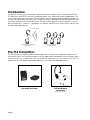
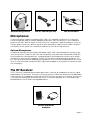
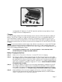
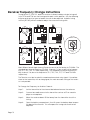
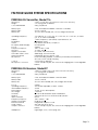
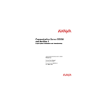
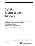
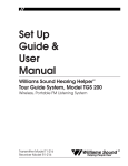
Williams Sound Corp.
Tour Guide
System
User Manual
For Models:
Systems:
Transmitters:
Receivers:
TGS SYS A
T16
R7, R7-4
Williams Sound TOUR GUIDE System
Contents:
Introduction
2
The Transmitter
2
Microphones
3
The Receiver
3
Headphones and Earphones
4
Operating Instructions
5
Hints for Using the System
6
Multiple System Operation
6
Battery Information
6
Re-Tuning the System
8
In Case of Difficulty
11
Warranty
12
Specifications
13
Williams Sound Corp.
Page 1
Introduction:
The FM Tour Guide System is a portable, high-performance, wireless system composed of the PPA
T16 Transmitter and PPA R7 Receivers and designed for use in hearing assistance applications. The
system allows one-way transmission of a tour guide’s voice to hearing impaired group members by
using an FM radio signal. Using the system helps to overcome background noise and distance from
the person speaking. The Tour Guide System can be used for large or small tour groups, in noisy or
quiet environments. Under FCC regulations, the Williams Sound FM Tour Guide System may only be
used for hearing assistance.
FM radio signal
Tour Guide uses Transmitter
and Microphone
Listeners use a Receiver
and Headphones
The T16 Transmitter:
The T16 Transmitter is a battery-powered belt pack that is used with a microphone to pick up the
tour guide's voice. The Transmitter produces an FM radio signal to broadcast the tour guide's voice
to the receiver units. A simple slide switch on top of the transmitter turns the unit on or off. The T16
operates on a 9 Volt alkaline disposable battery or a 9V NiMH rechargeable battery.
Tour Guide Transmitter
MIC 044 Headset
Microphone
(dual plug model shown)
Page 2
MIC 036 Hearing Protector
MIC 081, MIC 054 Lapel Clip
MIC 026 Hand-Held
Microphones:
A noise-cancelling, headset microphone (MIC 044) is the standard microphone. The noise-cancelling microphone helps to reduce background sounds in noisy environments. The microphone
plugs into the "MIC" jack on top of the Transmitter. The microphone is positioned directly in front of
the tour guide's mouth for maximum signal to noise ratio and so head movement does not affect
the loudness of the signal. The microphone cord acts as the transmitting antenna.
Optional Microphones:
An optional Hearing Protector Headset Microphone (MIC 036) is also available for extremely high
noise environments. It features ear muffs that completely cover both ears and provides 24 dB NRR
of attenuation for hearing protection. An optional Lapel Clip Microphone can be used in quieter
environments like museums or galleries. The MIC 081 has an omnidirectional pick-up pattern. The
MIC 054 has a directional (or cardioid) pick-up pattern, which will reduce background noise somewhat. A small hand-held microphone (MIC 026) is also available for tour guides who prefer to hold
the microphone.
The R7 Receiver:
The R7 Receiver is a battery-powered belt pack that is used with a headphone to hear the signal
produced by the Transmitter. The Receiver is pre-tuned to the Transmitter and has a user-adjustable
volume control. The headphone plugs into the "EAR/CHG" jack on top of the Receiver. The receiver
is turned on by rotating the volume control wheel. The receiver operates on a 9 Volt alkaline disposable battery or a 9V NiMH rechargeable battery.
Receiver and HED 021
Headphone
Page 3
HED 008 Hearing Protector
EAR 022 Surround Style
EAR 014, EAR 013 Mini Earphone
Headphones and Earphones:
The HED 001 Lightweight Headphone is the standard headset for the Tour Guide System. It offers
excellent sound quality and wearing comfort. The foam earpads may be removed for cleaning or
replacement. Replacement pads are part number HED 003-10.
The headphone plugs into the "EAR/CHG" jack on top of the Receiver. The headphones are wired
with a mono plug. If a stereo headphone is substituted, it will only work on one side of the headphone.
Optional Headphones and Earphones:
The HED 008 is a heavy-duty, hearing-protector headset. The HED 008 earmuffs completely cover
the ears and provide 24 dB NRR noise attenuation for hearing protection in high noise environments.
The EAR 022 Surround Earphone offers excellent sound quality in a unique style that hangs on the
ear. It is easy to keep clean since the earphone does not enter the ear. It is not recommended for
high noise environments.
The EAR 013 and EAR 014 are single and dual Mini Earphones. The earbud-style features a foam
covering that fits in the outer ear. The foam pads can be removed for cleaning or replacement.
Replacement pads are part number EAR 015-10.
Earpad Care:
Foam earpads may be removed and washed in a mild detergent, rinsed thoroughly, and air dried.
Replacement pads are also available from Williams Sound.
Page 4
Operating Instructions:
(Step 1)
Install the battery in the Transmitter. A 9V alkaline battery is included with the transmitter.
If you are using a 9 Volt rechargeable battery, see page 6. Open the battery door on
the Transmitter by lifting the battery door up. A coin may be used to help open the battery door. Carefully insert the battery, observing proper polarity. The large battery terminal (-) is nearest the top of the compartment.
DO NOT FORCE THE BATTERY IN BACKWARDS. DAMAGE TO THE TRANSMITTER WILL
RESULT!
Close the battery door by snapping it shut. If you are using a disposable battery, use
only 9V alkaline batteries (Eveready 522 or equiv.). A disposable battery should last 15
hours. A BAT 003 re-chargeable battery will last about 3 hours per charge.
Large terminal (-)
Battery Installation
(Step 2)
Plug the microphone into the "MIC/CHG" jack on top of the Transmitter. The Headset
Microphone boom should be positioned as close to the wearer's mouth as possible without actually touching. Lapel Clip microphones should be attached to a collar or lapel,
as close to the wearer's mouth as possible.
(Step 3)
The Transmitter can be placed in a pants pocket or clipped onto a belt or waistband in
the Belt Clip Case included with the Transmitter.
NOTE:
The microphone cord is the transmitting antenna. Do not bunch it up or wrap it around
the transmitter. Allow it to hang as straight as possible.
(Step 4)
Turn the Transmitter on by moving the slide switch on top of the Transmitter to "ON."
To conserve battery life, there is no indicator light. Make sure you turn the Transmitter off
when it is not in use to conserve the battery.
Receiver Operation:
(Step 1)
Install the battery in the Receiver. A 9V carbon battery is included with each receiver. If
you are using a rechargeable battery, see page 6. Open the battery door on the
Receiver by lifting the battery door up. A coin may be used to help open the battery
door. Carefully insert the battery, observing proper polarity. The large battery terminal (-)
is nearest the top of the compartment.
DO NOT FORCE THE BATTERY IN BACKWARDS. DAMAGE TO THE RECEIVER WILL RESULT!
Close the battery door by snapping it shut. If you are using a disposable battery, you
can use 9V carbon or alkaline batteries. A disposable carbon battery (Eveready 216 or
equiv.) should last 15 hours. A disposable alkaline battery (Eveready 522 or equiv.)
should last about 32 hours. A BAT 003 rechargeable battery will last about 6 hours per
charge.
(Step 2)
Plug the headphones or earphone into the "EAR/CHG" jack on top of the Receiver.
(Step 3)
Turn the Receiver on by rotating the volume control wheel. Adjust the volume to a comfortable level.
Page 5
Hints for Using the System:
Normal operating distance between the Transmitter and Receiver is about 100 feet (30m). The
operating range will vary in different buildings and surroundings. In some locations, the signal may
momentarily disappear. This is called a "drop-out" and is due to reflection and cancellation of the
radio signal. Moving a few feet will restore the signal.
Keep the Transmitter and Receiver units at least two feet apart. If the Transmitter gets too close to a
receiver, it can overload the Receiver, causing noisy reception or blocking of the signal.
Do not coil or bunch up the microphone or headphone cords. The cords act as antennas. Let
them hang at full length for the best results.
Do not use more than one Transmitter on the same channel (frequency) at the same time unless
they are physically separated by 50 to 100 feet (15 - 30 m). Operating more than one Transmitter
on the same channel at the same time in the same place will result in interference.
Using Multiple Systems for Multiple Groups:
For multiple tour groups within the same facility, multiple Tour Guide Systems may be operated on
the same channel at the same time by maintaining physical separation of 50 - 100 feet between
groups. The physical separation of groups takes advantage of the FM capture effect which causes
receivers to lock onto the closest transmitter.
Up to four systems can be operated simultaneously in the same facility if they all operate on different channels. Channels A,C,E, and G may be used simultaneously.
Additional Battery Information:
Recommended Batteries:
For Transmitters:
Eveready 522 Alkaline 9V or equivalent
BAT 003 rechargeable NiMH only
BAT 004, BAT 005, or CHG 1269A Chargers only for BAT 003
For Receivers:
Eveready 216 Carbon 9V, Eveready 522 Alkaline 9V or equiv.
BAT 003 rechargeable NiMH only
BAT 004, BAT 005, or CHG 1269 Chargers only for BAT 003
Battery Life:
For Transmitters:
For Receivers:
15 hours for Eveready 522 Alkaline 9V or equivalent
3 hours per charge for BAT 003 rechargeable
15 hours for Eveready 216 Carbon 9V or equivalent
32 hours for Eveready 522 Alkaline 9V or equivalent
6 hours per charge for BAT 003 rechargeable
If the sound becomes weak or distorted, replace the battery. The indicator light may still be on,
even with a battery that is weak. Do not leave dead batteries in the receivers.
Rechargeable Batteries:
(1)
Rechargeable batteries are shipped in a discharged condition. They must be charged
for 12 - 14 hours before using them. Make sure Transmitters and Receivers are turned
OFF while charging.
(2)
Williams Sound products are designed for use with a rechargeable battery (BAT 003)
and matching charger (BAT 004, BAT 005, or CHG 1269). This is the only type of rechargeable battery and charger we recommend. The BAT 003 has an 8.4 V nominal voltage
and 100mAh capacity, compared to only 7.2V and 60 mAh for other types of
Page 6
Batteries and Chargers
rechargeable "9V" batteries. The BAT 003 provides significantly longer battery life per
charge than lower voltage batteries.
Chargers:
The BAT 005 Single Charger has a cord that plugs into the receiver "EAR/CHG" jack to charge the
battery. The BAT 004 Charger has snaps for direct attachment of a 9V rechargeable battery. The
CHG 1269 Multiple Charger can charge 12 receivers simultaneously through the receiver "EAR"
jacks. See the instructions included with the CHG 1269 for more information. The battery does not
have to be removed from the receiver or transmitter for charging with the BAT 005 and CHG 1269
Chargers.
Do not mix and match batteries and chargers from different manufacturers. Using the BAT 003 battery with chargers designed for lower-voltage batteries can result in under-charging and unsatisfactory battery life. Using the BAT 004, BAT 005, or CHG 1269 Charger with low-voltage batteries can
result in over-charging and battery failure.
NOTE:
Do not dispose of batteries in fire. Do not open batteries - toxic chemicals inside.
DO NOT attempt to recharge disposable batteries!
Battery Charging Instructions:
(Step 1)
Make sure the Transmitter or Receiver is turned OFF while it is charging.
(Step 2)
To charge the battery without removing it from the Transmitter or Receiver, use the BAT
005 Charger or the CHG 1269 Multiple Charger. Plug the Charger cord into the earphone
jack (labeled EAR/CHG) on a Receiver. Plug the cord into the microphone jack (MIC) on
Transmitters. Then plug the Charger into an AC wall outlet. The Charger indicator light will
glow while the battery is charging. Charge for 12-14 hours. DO NOT CHARGE THE BATTERIES LONGER THAN 14 HOURS.
(Step 3)
To charge the battery outside the unit or to keep a spare battery charged, use the BAT
004 Charger. Remove the battery from its compartment and attach it to the snaps on
the Charger. Then plug the Charger into an AC wall outlet and charge for 12-14 hours.
The battery should be from the DO NOT CHARGE THE BATTERIES LONGER THAN 14 HOURS.
(Step 4)
Expected Battery Life: 6 hours per charge for a Receiver. 3 hours per charge for a
Transmitter. With normal service, the BAT 003 rechargeable battery should last approximately 1 year before it will need to be replaced.
Page 7
Instructions for the R7-4 Multi-Channel Receivers:
The multi-channel Receivers have a rotary selector knob on top which allows the user to select any
of four operating channels. The R7-4 tunes channels ACEG. These receivers are designed for use in
multiple channel systems with a number of tour groups or language groups.
Re-Tuning the TOUR GUIDE System:
Radio Interference:
The TOUR GUIDE System is usually not disturbed by other radio services, however there is no such
thing as a clear or exclusive channel for ANY radio service. One of the unique features of the
Williams Sound TOUR GUIDE System is that the operating frequency can easily be changed in the
field to avoid interference. There are ten possible frequencies for tour guide use (72-76 MHz). The
TOUR GUIDE System can be quickly changed to any of these frequencies by your Williams Sound
Authorized Dealer. The Transmitter is changed first. Then the signal produced by the Transmitter is
used to tune the receivers.
T16 Transmitter Frequency Change Procedure:
(Step 1)
Remove the Transmitter from the Belt Clip Case.
(Step 2)
Open the battery door and remove the battery.
(Step 3)
Grasp the right corner of the battery door and lift the flap up and to your left. The back
of the Transmitter case will open like a book, exposing the circuit board.
(Step 4)
Use the photo below to locate the channel selector switches.
(Step 5)
Use the tip of a paper clip or a small screwdriver (not a pencil point) to move the
switches to correspond with the switch positions on the programming chart. Select a
new frequency at least two channels away from the one you are experiencing interference on. DO NOT TOUCH ANY OF THE OTHER ADJUSTMENTS!
(Step 6)
Close the back of the Transmitter and install the battery. Plug the microphone in and
turn the Transmitter on to provide a tuning signal for the receivers. See the next section
for receiver tuning instructions.
Page 8
Setting the Transmitter Frequency:
Selector Switches
Transmitter Case Open
Switches set for 72.9
UP (OFF)
1 2 3 4 5 6 7 8
DOWN (ON)
Switches set for 72.9 MHz
Channel
A
B
C
D
E
F
G
H
I
J
Switch Settings
(MHz)
1
2
3
4
5
6
7
8
72.1
72.3
72.5
72.7
72.9
75.5
75.7
75.9
74.7
75.3
DN
DN
DN
DN
DN
UP
UP
UP
UP
UP
UP
UP
UP
UP
UP
UP
UP
UP
DN
UP
DN
DN
DN
DN
DN
DN
DN
DN
DN
DN
UP
UP
UP
UP
UP
UP
UP
UP
UP
UP
DN
UP
DN
UP
DN
UP
DN
UP
UP
DN
DN
DN
DN
DN
DN
DN
DN
DN
DN
DN
DN
DN
UP
UP
DN
DN
UP
UP
DN
DN
DN
DN
DN
DN
UP
DN
DN
DN
UP
DN
Page 9
Receiver Frequency Change Instructions
Tuning for the R7, R30, R31, and R32 receivers is determined by a single tuning coil.
In the R7-4 and R7-6, one coil is assigned to each switch position. See the following
6 figures and receiver types to locate the coils to be adjusted. A plastic tuning
wrench (PLT 005) will be needed to adjust these receiver tuning coils.
1
1
2
2
IC01
TUNING COIL
R30
R- 31
R-32
Ferrite Tuning
"Slug"
5
1
R7Y
R7- 4
2
3
4
R7- 6
1
2
3
6
4
Most Williams Sound single channel Receivers are set at the factory to 72.9 MHz. The
standard four-channel receivers (R7-4NA), Channels 1-4, are usually set to frequencies 72.1, 72.5, 72.9, 75.7 MHz respectively. The standard six-channel receivers (R76N), channels 1-6, are set to frequencies 72.1, 72.5, 72.9, 75.7, 74.7 and 75.3 MHz
respectively.
The Receiver must be tuned with a weak and somewhat noisy signal. If tuned too
close to the transmitter, with a strong signal, the most accurate tuning of the receiver is not possible.
To Change the Frequency to Another Channel:
Page 10
Step 1:
Set the transmitter to the channel desired and remove the antenna.
Step 2:
Connect an audio source to the transmitter such as a CD or cassette
player or microphone.
Step 3:
Move the receiver about 25 feet away from the transmitter to set the
tuning.
Step 4:
Open the battery compartment, then lift up on the battery door to open
the back of the receiver. This will expose the tuning coil or coils to be
adjusted.
Step 5:
Locate the Tuning Coil. (See figure on previous page). Each tuning coil is
a small, square, shiny metal can with a screwdriver slot in a tuning slug in
the top center. The Tuning Slug is usually black or gray.
Step 6:
With the earphone or headphone supplied with the receiver plugged
into the Ear Jack, turn the volume control to a comfortable level, and lis
ten for the transmitted signal.
Step 7:
Gently put the tip of the tuning wrench into the slot in the tuning slug. Be
careful not to push hard on the slug so as not to damage the threads in
the coil, and do not screw it down more than 3 turns into the coil.
Step 8:
Turn the tuning slug in a counter-clockwise direction about two turns.
Then, slowly turn the tuning slug in the clockwise direction until the signal
is heard. There may be two signal points heard. The one which is
received first is a false response. Be sure to continue tuning slightly further
to the correct point, which will be much louder. Tune back and forth to
find the center of the point of best response to the program being heard.
Step 9:
Mark down the date, and if a new frequency has been chosen, mark it
down inside the receiver case for future reference.
In Case of Difficulty:
If your TOUR GUIDE System is not working, check the following:
(1)
Make sure the batteries are fresh or completely charged and installed with the correct
polarity.
(2)
Make sure the microphone is plugged into the Transmitter and the headphone is
plugged into the Receiver. They will not work if they are reversed.
(3)
Move the Transmitter and Receiver closer together. You may be out of range. When
using the system indoors, it is normal for the signal to momentarily disappear in certain
locations. This is called a "drop-out". Moving a few feet will restore the signal.
(4)
Make sure that the Transmitter and Receivers are tuned to the same channel. The units
have stickers inside the back cover identifying the channel.
(5)
Do not try to use more than one Transmitter on the same channel in close proximity to
each other. MORE THAN ONE TRANSMITTER ON THE SAME CHANNEL WILL RESULT IN INTERFERENCE IF THEY ARE CLOSE TOGETHER. Keep the systems 50 - 100 feet apart or use separate channels for each system used.
(6)
If the rechargeable batteries will only work for a short period of time (less than 1 hour)
even after it is fully charged, it must be regenerated. Leave it in the unit, with the unit
turned on, for 5 - 6 hours Then turn the unit off and charge for 14 - 16 hours. This should
restore normal battery life. The rechargeable battery will gradually lose its capacity over
time and should be replaced every year.
(7)
If you are still hearing interference on the Receivers, turn the Transmitter off and listen
with a receiver. If you hear the interference with the Transmitter off, you need to
change to a clear channel. See the re-tuning instructions.
Page 11
Warranty
The Williams Sound Tour Guide System is engineered and designed to provide you with many years
of reliable service. Williams Sound warrants it against defects in materials and workmanship for FIVE
(5) years EXCEPT FOR earphones, headphones, rechargeable batteries, chargers, cables, antennas, carry cases, and all other accessory products. Accessory products carry a 90 day warranty.
If the product fails within the specified warranty period, Williams Sound will determine whether to
repair or replace the defective equipment. This warranty does not apply to physical damage,
abuse, mis-use, or products that have been modified.
If you experience difficulty with your system, call for Customer Assistance:
1-800-328-6190.
If it is necessary to return the system for service, a Williams Sound representative will give you a
Return Authorization Number (RA) and shipping instructions.
Pack the system carefully and send it to:
Williams Sound Corp.
10321 West 70th Street
Eden Prairie, MN 55344-3459 USA
Phone: 800-843-3544
952-943-2252
Fax:
952-943-2174
TTY:
952-943-9675
e-mail: [email protected]
Your warranty becomes effective the date you purchase your system. Your returned warranty card
is our way of knowing when your warranty begins. It also gives us important information about your
system including the serial number. This information will help us serve you better in the future. Please
take a moment to complete and mail the attached card. Thank you.
Page 12
FM TOUR GUIDE SYSTEM SPECIFICATIONS
PERSONAL PA Transmitter, Model T16
Dimensions:
Weight:
Color and Material:
3-5/8" L x 2-3/8" W x 7/8" H (92.1mm x 60.3 mm x 22.2 mm)
3.2 oz (90 g) with 9V battery
Gray, polyallomer
Battery Type:
Battery Drain:
Battery Life:
9 Volt, Eveready 522 Alkaline or BAT 003 7-cell NiMH,
30 mA, nominal
15 hours with Eveready 522, 3 hours/charge with BAT 003
Operating Frequency:
*10 channels, 72.1, 72.3, 72.5, 72.7, 72.9, 75.5, 75.7, 75.9, 74.7, 75.3 MHz
(Ch. G, 75.7 MHz is standard)
+ .005%, frequency synthesized, crystal reference, PLL
Wideband, 75 KHz
Fast-attack, fast decay compressor
50 mW typical
CNMT16
100 to 10 KHz, + 3 dB
1% max., THD
50 - 55 dB, with R7 Receiver
40dB range, 30 mV threshold
Integral with 40" microphone cord
Noise-cancelling headset, condenser, powered by the transmitter,
40" cord, 3.5 mm mini phone plug.
On/Off switch, slide-type
3.5 mm mini phone jack, also serves as a charging jack for rechargeable
battery
Stability:
Modulation:
Limiter:
RF Output (Field Strength):
FCC ID:
Frequency Response:
Distortion:
Signal-to-Noise Ratio:
Automatic Gain Control:
Transmit Antenna:
Microphone:
Controls:
Microphone Connector:
PERSONAL PA Receiver, Model R7
Dimensions:
Weight:
Color and Material:
3-5/8"L x 2-3/8"W x 7/8" H (92.1mm x 60.3mm x 22.2mm)
3.2 oz (90 g) with 9V battery
Gray, polyallomer
Battery Type:
Battery Drain:
Battery Life:
9 Volt, Eveready 522 Alkaline or BAT 003 NiMH
14 mA, nominal
32 hours with Eveready 522, 6 hrs/charge with BAT 003
FCC ID:
Operating Frequency:
Intermediate Frequency:
FM Deviation:
AFC Range:
Sensitivity:
Squelch:
Input Overload:
Frequency Response:
Signal-to-Noise Ratio:
Receive Antenna:
Audio Output:
Output Connector:
CNMR7
*Pre-Tuned, Adjustable, 72 MHz - 76 MHz
70 KHz
15 KHz, 75 µsec de-emphasis
+ 300 KHz
2 uV at 12 dB Sinad with squelch defeated
Squelches at 10 uV for minimum 50 dB S/N ratio
20 mV
100 to 10KHz, + 3 dB
50 dB at 10 uV
Integral with earphone cord
250 mW, max. at 16 Ohms
3.5 mm mini phone jack, also serves as a charging jack for rechargeable
battery
Lightweight, mono, 3.5mm plug, 16Ω
Headphone:
Page 13
Williams Sound Corp.
10321 West 70th St., Eden Prairie, MN 55344-3459
U.S.A. 800-328-6190 / 952-943-2252 / FAX: 952-943-2174
www.williamssound.com
© 2003 Williams Sound Corp.
MAN 015F