1
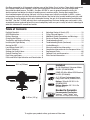
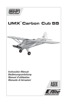
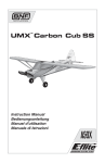
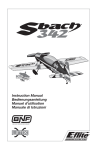
™ ® UMX GEE BEE R2 Instruction Manual Bedienungsanleitung Manuel d’utilisation Manuale di Istruzioni EN NOTICE All instructions, warranties and other collateral documents are subject to change at the sole discretion of Horizon Hobby, Inc. For up-to-date product literature, visit www.horizonhobby.com and click on the support tab for this product. Meaning of Special Language: The following terms are used throughout the product literature to indicate various levels of potential harm when operating this product: NOTICE: Procedures, which if not properly followed, create a possibility of physical property damage AND little or no possibility of injury. CAUTION: Procedures, which if not properly followed, create the probability of physical property damage AND a possibility of serious injury. WARNING: Procedures, which if not properly followed, create the probability of property damage, collateral damage, and serious injury OR create a high probability of superficial injury. WARNING: Read the ENTIRE instruction manual to become familiar with the features of the product before operating. Failure to operate the product correctly can result in damage to the product, personal property and cause serious injury. This is a sophisticated hobby product. It must be operated with caution and common sense and requires some basic mechanical ability. Failure to operate this product in a safe and responsible manner could result in injury or damage to the product or other property. This product is not intended for use by children without direct adult supervision. Do not attempt disassembly, use with incompatible components or augment product in any way without the approval of Horizon Hobby, Inc. This manual contains instructions for safety, operation and maintenance. It is essential to read and follow all the instructions and warnings in the manual, prior to assembly, setup or use, in order to operate correctly and avoid damage or serious injury. Age Recommendation: Not for children under 14 years. This is not a toy. 2 EN Gee Bees competed in all the popular airplane races of the Golden Era of aviation. These highly engineered, tear-shaped, super planes required a skillful hand and perfect circumstances, but with the right pilot, they ruled the speed course. The UMX™ Gee Bee® R2 BNF is yours to groove through the skies just about anywhere and deliver the kind of handling more in common with a Sunday sport-model than a short-coupled engine with wings. Not only is the tear-shape racer faithfully mastered, its AS3X™ system enhancement assures that this distinctive replica delivers the kind of ultra smooth handling and rock solid control the Granville brothers surely only dreamed of having. You get all of the performance possible from the UMX™ Gee Bee® R2 BNF with only basic radio programming. And even though your new model is fully assembled, please read and follow this manual completely to be sure you’re ready to take full advantage of what this awesome RC aircraft has to offer. Table of Contents Preflight Checklist .................................................4 AS3X Stabilization.................................................4 Battery Warnings ..................................................4 Charging the Battery .............................................5 Transmitter and Receiver Binding .........................6 Installing the Flight Battery ..................................6 Arming the ESC ....................................................7 Low Voltage Cutoff (LVC) .......................................7 Control Centering ..................................................8 Settings for Control Horns .....................................8 Control Direction Test ............................................8 Dual Rates and Expos ...........................................9 DX4e and DX5e Expo Activation and Deactivation .9 20.1 in (510mm) Adjusting Center of Gravity (CG) ..........................10 Flying Tips and Repairs .......................................11 Additional Safety Precautions and Warnings ........12 Service of Power Components ............................13 Troubleshooting Guide ........................................14 Troubleshooting Guide (Continued) ......................15 Limited Warranty ................................................16 Warranty and Service Information .......................17 Compliance Information for the European Union ..17 Replacement Parts..............................................66 Optional Parts and Accessories ...........................67 Parts Contact Information ...................................68 Installed 13.9 in (352mm) BL180 (Brushless) Outrunner Motor, 3000Kv (EFLUM180BLB) DSM2 6Ch Ultra Micro AS3X Receiver BL-ESC (EFLU4864) (4) 2.3-Gram Performance Linear Long Throw Servo (SPMSA2030L) Battery: 200mAh 2S 25C Li-Po (EFLB2002S25) Battery Charger: 2S 7.4V Li-Po (EFLUC1007) Needed to Complete Recommended Transmitter: 3.60 oz (102 g) Spektrum™ DSM2™/DSMX® with dual-rates and expo (DX4e and up) To register your product online, go to www.e-fliterc.com 3 EN Preflight Checklist 1. Charge flight battery. 6. Set dual rates and exponential. 2. Install flight battery in aircraft (once it has been fully charged). 7. Adjust center of gravity 3. Bind aircraft to transmitter. 8. Perform a radio system Range Check. 4. Make sure linkages move freely. 9. Find a safe and open area. 5. Perform Control Direction Test with transmitter. 10. Plan flight for flying field conditions. AS3X Stabilization DELIVERS BREAKTHROUGH PERFORMANCE The AS3X system for airplanes is an electronic enhancement system that makes it possible for you to experience super-smooth flight performance, yet still have full control authority for sport or scale flight. Turbulence, torque and tip stalls are just some of the many complications to assess when trying to achieve smooth flight. The Horizon Hobby worldclass team of RC pilots developed the AS3X system for airplanes based on the successful use of AS3X with ultra micro flybarless helicopters. Specially tuned for airplanes, the AS3X system invisibly helps with complicated corrections, allowing you to experience ultra-smooth flight performance that feels so natural that you’ll quickly build confidence in the capability of the airplane. AS3X system setup is simple. Just bind your DSM2™/DSMX® transmitter to the model using a basic airplane program and AS3X will assure that the locked-in feel and control authority you want is instantly at your command to help show off your RC pilot skills. AS3X will innovate the way you’ll want to fly now and in the future. To see what we mean, go to www.E-fliteRC.com/AS3X. Battery Warnings The included battery charger (EFLUC1007) has been designed to safely charge the Li-Po battery. CAUTION: All instructions and warnings must be followed exactly. Mishandling of Li-Po batteries can result in a fire, personal injury, and/or property damage. • By handling, charging or using the included Li-Po battery you assume all risks associated with lithium batteries. • If at any time the battery begins to balloon or swell, discontinue use immediately. If charging or discharging, discontinue and disconnect. Continuing to use, charge or discharge a battery that is ballooning or swelling can result in fire. • Always store the battery at room temperature in a dry area for best results. • Always transport or temporarily store the battery 4 in a temperature range of 40–120º F. Do not store battery or model in a car or direct sunlight. If stored in a hot car, the battery can be damaged or even catch fire. • Always charge batteries away from flammable materials. • NEVER USE AN Ni-Cd OR Ni-MH CHARGER. Failure to charge the battery with a compatible charger may cause fire resulting in personal injury and/or property damage • Never discharge Li-Po cells to below 3V under load. • Never cover warning labels with hook and loop strips. • Never leave charging batteries unattended. • Never charge batteries outside safe temperature range. • Never charge damaged batteries. EN Charging the Battery Your aircraft comes with a 2-Cell 7.4V 200mAh 25C Li-Po battery and a Celectra™ 2S 7.4V DC Li-Po Charger that requires a 12V (11V-14V) DC power source. Refer to the battery warnings. It is recommended to charge the battery pack while you are inspecting the aircraft. The flight battery will be required to confirm proper aircraft operation in future steps. Please visit www.horizonhobby.com for optional battery adapters. 2S 7.4V 200mAh 25C Lithium Polymer Battery The Battery Charging Process 1. Charge only batteries that are cool to the touch and are not damaged. Look at the battery to make sure it is not damaged e.g., swollen, bent, broken or punctured. 2. The connector of the battery is specifically designed to allow it to fit into the charge port one way to prevent reverse polarity connection. However, check for proper alignment and polarity before proceeding to the next step. 3. Gently press the battery connector into the charge port located on the front of the charger. 4. When you make the connection successfully, the green LED blinking on the charger slows, indicating proper connection. 5. Press the button on the charger. The red LED will illuminate, indicating charging has begun. 6. Charging a fully discharged (not over-discharged) 200mAh battery takes approximately 50–60 min- utes at the charger’s 300mA charge rate. The included battery can be charged at a rate of up to 3C (600mA). 7. When the battery is fully charged, the green LED will turn solid. 8. Always unplug the battery from the charger immediately upon completion of charging. CAUTION: Overcharging a battery can cause a fire. CAUTION: Only use a charger specifically designed to charge a Li-Po battery. Failure to do so could result in fire causing injury or property damage. CAUTION: Never exceed the recommended charge rate. LED Functions under normal operation 1. Green LED blinking with power connected but without battery ................................... Standby 2. Green LED blinking .................................................................................................... Battery is connected 3. Blinking Red LED at varying speeds ........................................................................... Charging 4. Red and Green LED blinking simultaneously ............................................................... Balancing 5. Solid Green LED ....................................................................................................... Full Charge 6. Red and Green LED flashing rapidly ........................................................................... Error 5 EN Transmitter and Receiver Binding Binding is the process of programming the receiver of the control unit to recognize the GUID (Globally Unique Identifier) code of a single specific transmitter. You need to ‘bind’ your chosen SpektrumTM DSM2™/ DSMX® technology equipped aircraft transmitter to the receiver for proper operation. Any JR® or Spektrum DSM2/DSMX transmitter can bind to the AS3X™ DSM® receiver. For best flight performance of the UMX™ Gee Bee R2™, it is recommended that you use a transmitter with exponential and dual rates. Please visit www.bindnfly.com for a complete list of compatible transmitters. NOTICE: When using a Futaba® transmitter with a Spektrum DSM module, reversing the throttle channel is required. Binding Procedure 1. Refer to your transmitter’s unique instructions for binding to a receiver. 2. Make sure the flight battery is disconnected from the aircraft. 3. Power off the transmitter. 4. Connect the flight battery in the aircraft. The receiver LED will begin to flash rapidly, (typically after 5 seconds). 5. Make sure the transmitter controls are at neutral and the throttle and throttle trim are in the low position. 6. Put your transmitter into bind mode. Refer to your transmitter’s manual for binding button or switch instructions. 7. After 5 to 10 seconds, the receiver status LED will become solid, indicating that the receiver is bound to the transmitter. If the LED does not turn solid, refer to the Troubleshooting Guide at the back of the manual. For subsequent flights, power on the transmitter for 5 seconds before connecting the flight battery. Installing the Flight Battery 1. Remove the battery hatch. 2. Attach the flight battery to the hook and loop strip (A) on the battery tray. See the Adjusting the Center of Gravity instructions for the battery’s position. 3. Place the aircraft on the ground out of the wind and connect a fully charged flight battery. Ensure the aircraft is immobile for 5 seconds so the AS3X system initializes correctly. See the Arming the ESC instructions for correct connection of the battery to the ESC. 4. Install the battery hatch. NOTICE: If using a different battery than the recommended 2-Cell 7.4V 200mAh 25C Li-Po, you will need to apply a circle of hook and loop fastener to the battery in order to hold the battery in place. CAUTION: Always disconnect the Li-Po battery from the aircraft receiver when not flying to avoid over-discharging the battery. Batteries discharged to a voltage lower than the lowest approved voltage may become damaged, resulting in loss of performance and potential fire when batteries are charged. 6 A EN Arming the ESC Arming the ESC also occurs after binding as previously described, but subsequent connection of a flight battery requires the steps below. Lower throttle and throttle trim to lowest settings. Power on the Transmitter then wait 5 seconds Install flight battery and connect it to the ESC. Keep plane immobile and away from wind for 5 seconds. Series of tones Continuous LED If you accidentally connect the battery while the throttle is fully raised, the ESC will enter programming mode. Disconnect the battery immediately. The AS3X system will not activate until the throttle stick or trim is increased for the first time. Once the AS3X is active, the control surfaces may move rapidly on the aircraft. This is normal. AS3X will remain active until the battery is disconnected. CAUTION: Always keep hands away from the propeller. When armed, the motor will turn the propeller in response to any throttle movement. Low Voltage Cutoff (LVC) When a Li-Po battery is discharged below 3V per cell, it will not hold a charge. The aircraft’s ESC protects the flight battery from over-discharge using Low Voltage Cutoff (LVC). Before the battery charge decreases too much, LVC removes power supplied to the motor. Power to the motor quickly decreases and increases, showing that some battery power is reserved for flight control and safe landing. When the motor power pulses, land the aircraft immediately and recharge the flight battery. Disconnect and remove the Li-Po battery from the aircraft after use to prevent trickle discharge. Before storage, charge the Li-Po battery to full capacity. During storage, make sure battery charge does not fall below 3V per cell. Tip: Due to the quiet nature of the aircraft, you may not hear the pulsing of the motor. For your first flights, set your transmitter timer or a stopwatch to 3 minutes. Adjust your timer for longer or shorter flights once you have flown the model. Flights of 4.5 minutes or more are achievable if using proper throttle management. NOTICE: Repeated flying to LVC will damage the battery. 7 EN Control Centering Before the first flights, or in the event of an accident, make sure the flight control surfaces are centered. Adjust the linkages mechanically if the control surfaces are not centered. Use of the transmitter sub-trims may not correctly center the aircraft control surfaces due to the mechanical limits of linear servos. 1. Make sure the control surfaces are neutral when the transmitter controls and trims are centered. The transmitter sub-trim must be always be set to zero. 2. When needed, use a pair of pliers to carefully bend the metal linkage (see illustration). 3. Make the U-shape narrower to make the connector shorter. Make the U-shape wider to make the linkage longer. Centering Controls After First Flights For best performance with AS3X, it is important that excessive trim is not used. If the model requires excessive transmitter trim (4 or more clicks of trim per channel), return the transmitter trim to zero and adjust the linkages mechanically so that the control surfaces are in the flight trimmed position. 1mm offset of Rudder After centering the rudder, we recommend adjusting the rudder linkage so the rudder center is 1mm right (measured at the trailing edge of the rudder) from center while rudder trim on your transmitter is at neutral. 1mm Settings for Control Horns The following illustration shows the factory settings for linkages on the control horns. After flying, carefully adjust the linkage positions for the desired control response. Aileron Elevator Rudder Control Direction Test You should bind your aircraft and transmitter before doing these tests. Move the controls on the transmitter to make sure aircraft control surfaces move correctly and in the proper direction. Make sure tail linkages move freely and that paint or decals are not adhered to them. 8 EN If using the DX4e or DX5e transmitters, we recommend activating Expo for smoother control. For activation and deactivation of the Expo in the DX4e and DX5e, see the next section. NOTICE: Do not set your transmitter travel adjust over 100%. If the TRAVEL ADJUST is set over 100%, it will not result in more control movement, it will overdrive the servo and cause damage. It is normal for linear servos to make significant noise. The noise is not an indication of a faulty servo. High Rate Low Rate Aileron 100% 70% Elevator 100% 70% Rudder 100% 70% High Rate Expos To obtain the best flight performance, we recommend using a DSM2/DSMX radio capable of Dual Rates and Expo. The suggested settings shown here are the recommended starting settings. Adjust according to the individual preferences after the initial flight. Dual Rates Dual Rates and Expos Aileron 0% Low Rate 0% Elevator 10% 0% Rudder 0% 0% Tip: For the first flight, fly the model in low rate. Tip: For landing, we recommend using high rate elevator. DX4e and DX5e Expo Activation and Deactivation If you plan to fly your Gee Bee R2 with a DX4e or DX5e, disconnect the battery from the aircraft before activating the Expo feature in your transmitter. Once Expo is activated, it will remain activated for use subsequent power cycles of the transmitter. Once Expo is deactivated, it will remain deactivated until it is activated again. DX4e (Modes 1 and 2) Activate and Deactivate Expo 1. Put the ACT switch in the down position (ON) and the Rate switch in the down position (LO). 2. Push and hold the trainer (bind) button and move and hold the two sticks (as shown here) for activation (A) or deactivation (B), while powering on the transmitter. A B 3. Release the trainer switch and the control sticks only after a series of tones sound (ascending tones for activation, descending tones for deactivation). DX5e (Modes 1 and 2) Activate Expo 1. Hold the aileron trim switch to the right when powering on the transmitter. 2. Release the aileron trim switch after a series of ascending tones to confirm that Expo is activated. Deactivate Expo 1. Hold the aileron trim switch to the left when powering on the transmitter. 2. Release the aileron trim switch after a series of descending tones to confirm that Expo is deactivated. 9 EN Adjusting Center of Gravity (CG) The CG location is 26mm back from leading edge of the wing at the root. This CG location has been determined with the included 2S 200mAh 7.4V Li-Po battery installed in the front of the battery cavity. The battery tray is oversized to allow for Center of Gravity adjustment. Start by placing the battery at the front edge of the battery tray with the connector plug facing the rear of the aircraft. Adjust as needed by sliding the battery back or forward. 26mm 10 EN Flying Tips and Repairs Flying We recommend flying your E-flite® UMX Gee Bee R2 outside in moderate winds or in a large gymnasium. Always avoid flying near houses, trees, wires and buildings. You should also be careful to avoid flying in areas where there are many people, such as busy parks, schoolyards or soccer fields. Consult local laws and ordinances before choosing a location to fly your aircraft. Takeoff Place the Gee Bee R2 in position for takeoff (facing into the wind if flying outdoors). Gradually increase the throttle to full power, holding a small amount of up elevator and steering with the rudder. Climb gently to check trim. Once the trim is adjusted, begin exploring the flight envelope of the Gee Bee R2 Landing Land into the wind. This is very important for this model. Fly the aircraft to approximately 6 inches (15cm) or less above the runway, using a small amount of throttle for the entire descent. Keep the throttle on until the aircraft is ready to flare. During flare, keep the wings level and the airplane pointed into the wind. Gently lower the throttle while pulling back on the elevator to bring the aircraft down on all three wheels. Failure to lower the throttle CAUTION stick and trim to the lowest possible positions during a crash could result in damage to the ESC in the receiver unit, which may require replacement. Over Current Protection (OCP) Always The Gee Bee R2 is decrease throttle at equipped with Over Current propeller strike. Protection. OCP protects the ESC from overheating and stops the motor when the transmitter throttle is set too high and the propeller cannot turn. OCP will only activate when the throttle is positioned just above 1/2 throttle. After the ESC stops the motor, fully lower the throttle to re-arm the ESC. Repairs Crash damage is not covered under warranty. Repair this model using foam-compatible CA glue or clear tape. Only use foam-compatible CA glue as other types of glue can damage the foam. When parts are not repairable, see the Replacement Parts List for ordering by item number. For a listing of all replacement and optional parts, refer to the list at the back of this manual. NOTICE: Use of foam-compatible CA accelerant on your model can damage paint. DO NOT handle the model until accelerant fully dries. 11 EN Additional Safety Precautions and Warnings As the user of this product, you are solely responsible for operating it in a manner that does not endanger yourself and others or result in damage to the product or the property of others. This model is controlled by a radio signal subject to interference from many sources outside your control. This interference can cause momentary loss of control, so it is advisable to always keep a safe distance in all directions around your model as this space will help avoid collisions or injury. • Always keep a safe distance in all directions around your model to avoid collisions or injury. • Always operate your model in open spaces away from full-size vehicles, traffic and people. • Always carefully follow the directions and warnings for this and any optional support equipment (chargers, rechargeable battery packs, etc.). • Always keep all chemicals, small parts and anything electrical out of the reach of children. • Always avoid water exposure to all equipment not specifically designed and protected for this purpose. Moisture causes damage to electronics. • Never place any portion of the model in your mouth as it could cause serious injury or even death. • Never operate your model with low transmitter batteries. Post Flight Checklist 1. Disconnect flight battery from ESC (Required for Safety and battery life). 5. Store flight battery apart from aircraft and monitor the battery charge. 2. Power off transmitter. 6. Make note of flight conditions and flight plan results, planning for future flights. 3. Remove flight battery from aircraft. 4. Recharge flight battery. 12 EN Service of Power Components Disassembly CAUTION: DO NOT handle propeller parts while the flight battery is connected. Personal injury could result. Propeller 1. The front of the cowling covers the battery compartment. Lift the cowling to access the battery compartment. C A 2. Carefully remove the screw (A) and the propeller (B) from the motor shaft (C). B Motor and Firewall 1. Remove 2 screws (D), the firewall (E) and the motor (F) from the fuselage motor mount (G). The motor magnet may attract screws to the motor. E F G D 2. Remove the screw (H) from the firewall (E) and motor (F). 3. Disconnect the motor wire connectors from the ESC/receiver connectors. Assembly Motor and Firewall 1. Connect the motor wire connectors to the ESC/receiver connectors so the wire colors align. 2. Install the motor in the firewall using a screw in the top of the firewall. 3. Attach the firewall to the fuselage motor mount using 2 screws. Propeller 1. Install the propeller on the motor shaft using a screw.Numbers on the propeller must face out from fuselage for correct propeller operation. 2. Put the foam battery hatch on the fuselage and slide it back to fully engage the fuselage. H E F Removing tape or decals may remove paint from the fuselage. 13 EN Troubleshooting Guide AS3X Problem Possible Cause Solution Control surfaces may not have been Control surfaces not mechanically centered from factory at neutral position when transmitter Aircraft was moved after the flight battery controls are at neutral was connected and before sensors initialized Center control surfaces mechanically by adjusting the U-bends on control linkages Model flies inconsistently from flight to flight Trims are moved too far from neutral position Neutralize trims and mechanically adjust linkages to center control surfaces Controls oscillate in flight (model rapidly jumps or moves) Propeller is unbalanced causing excessive vibration Remove propeller and rebalance or replace it if damaged Prop screw is too loose, causing vibration Tighten the prop screw Problem Aircraft will not respond to throttle but responds to other controls Extra propeller noise or extra vibration Reduced flight time or aircraft underpowered LED on receiver flashes and aircraft will not bind to transmitter (during binding) 14 Disconnect and reconnect the flight battery while keeping the aircraft still for 5 seconds Possible Cause Solution Throttle stick and/or throttle trim too high Reset controls with throttle stick and throttle trim at lowest setting Throttle channel is reversed Reverse throttle channel on transmitter Motor disconnected from receiver Open fuselage and make sure motor is connected to the receiver Damaged propeller, spinner or motor. Replace damaged parts Prop screw is too loose Tighten the prop screw Prop out of balance Balance the prop Flight battery charge is low Completely recharge flight battery Propeller installed backwards Install propeller with numbers facing forward Flight battery damaged Replace flight battery and follow flight battery instructions Flight conditions may be too cold Make sure battery is warm before use Battery capacity too low for flight conditions Replace battery or use a larger capacity battery Transmitter too near aircraft during binding process Power off transmitter, move transmitter a larger distance from aircraft, disconnect and reconnect flight battery to aircraft and follow binding instructions Bind switch or button not held long enough during bind process Power off transmitter and repeat bind process. Hold transmitter bind button or switch until receiver is bound EN Troubleshooting Guide (Continued) Problem LED on receiver flashes rapidly and aircraft will not respond to transmitter (after binding) Control surface does not move Possible Cause Solution Less than a 5-second wait between first powering on transmitter and connecting flight battery to aircraft Leaving transmitter on, disconnect and reconnect flight battery to aircraft Aircraft bound to different model memory (ModelMatch™ radios only) Select correct model memory on transmitter and disconnect and reconnect flight battery to aircraft Flight battery/transmitter battery charge is too low Replace/recharge batteries Control surface, control horn, linkage or servo damage Replace or repair damaged parts and adjust controls Wire damaged or connections loose Do a check of wires and connections, connect or replace as needed Flight battery charge is low Fully recharge flight battery Control linkage does not move freely Make sure control linkage moves freely Controls reversed Transmitter settings reversed Adjust controls on transmitter appropriately Motor loses power Damage to motor or power components Do a check of motor and power components for damage (replace as needed) Motor power quickly decreases and increases then motor loses power Battery power is down to the point of receiver/ESC Low Voltage Cutoff (LVC) Recharge flight battery or replace battery that is no longer performing Motor/ESC is not armed after landing Over Current Protection (OCP) stops the motor when the transmitter throttle is set high and the propeller cannot turn Fully lower throttle and throttle trim to arm ESC Servo locks or freezes Travel adjust value is set above 100% at full travel overdriving the servo Set Travel adjust to 100% or less and/or set sub-trims to Zero and adjust linkages mechanically 15 EN Limited Warranty What this Warranty Covers Horizon Hobby, Inc. (“Horizon”) warrants to the original purchaser that the product purchased (the “Product”) will be free from defects in materials and workmanship at the date of purchase. What is Not Covered This warranty is not transferable and does not cover (i) cosmetic damage, (ii) damage due to acts of God, accident, misuse, abuse, negligence, commercial use, or due to improper use, installation, operation or maintenance, (iii) modification of or to any part of the Product, (iv) attempted service by anyone other than a Horizon Hobby authorized service center, or (v) Products not purchased from an authorized Horizon dealer. OTHER THAN THE EXPRESS WARRANTY ABOVE, HORIZON MAKES NO OTHER WARRANTY OR REPRESENTATION, AND HEREBY DISCLAIMS ANY AND ALL IMPLIED WARRANTIES, INCLUDING, WITHOUT LIMITATION, THE IMPLIED WARRANTIES OF NON-INFRINGEMENT, MERCHANTABILITY AND FITNESS FOR A PARTICULAR PURPOSE. THE PURCHASER ACKNOWLEDGES THAT THEY ALONE HAVE DETERMINED THAT THE PRODUCT WILL SUITABLY MEET THE REQUIREMENTS OF THE PURCHASER’S INTENDED USE. Purchaser’s Remedy Horizon’s sole obligation and purchaser’s sole and exclusive remedy shall be that Horizon will, at its option, either (i) service, or (ii) replace, any Product determined by Horizon to be defective. Horizon reserves the right to inspect any and all Product(s) involved in a warranty claim. Service or replacement decisions are at the sole discretion of Horizon. Proof of purchase is required for all warranty claims. SERVICE OR REPLACEMENT AS PROVIDED UNDER THIS WARRANTY IS THE PURCHASER’S SOLE AND EXCLUSIVE REMEDY. Limitation of Liability HORIZON SHALL NOT BE LIABLE FOR SPECIAL, INDIRECT, INCIDENTAL OR CONSEQUENTIAL DAMAGES, LOSS OF PROFITS OR PRODUCTION OR COMMERCIAL LOSS IN ANY WAY, REGARDLESS OF WHETHER SUCH CLAIM IS BASED IN CONTRACT, WARRANTY, TORT, NEGLIGENCE, STRICT LIABILITY OR ANY OTHER THEORY OF LIABILITY, EVEN IF HORIZON HAS BEEN ADVISED OF THE POSSIBILITY OF SUCH DAMAGES. Further, in no event shall the liability of Horizon exceed the individual price of the Product on which liability is asserted. As Horizon has no control over use, setup, final assembly, modification or misuse, no liability shall be assumed nor accepted for any resulting damage or injury. By the act of use, setup or assembly, the user accepts all resulting liability. If you as the purchaser or user are not prepared to accept the liability associated with the use of the Product, purchaser is advised to return the Product immediately in new and unused condition to the place of purchase. Law These terms are governed by Illinois law (without regard to conflict of law principals). This warranty gives you specific legal rights, and you may also have other rights which vary from state to state. Horizon reserves the right to change or modify this warranty at any time without notice. 16 Warranty Services Questions, Assistance, and Services Your local hobby store and/or place of purchase cannot provide warranty support or service. Once assembly, setup or use of the Product has been started, you must contact your local distributor or Horizon directly. This will enable Horizon to better answer your questions and service you in the event that you may need any assistance. For questions or assistance, please direct your email to productsupport@ horizonhobby.com, or call 877.504.0233 toll free to speak to a Product Support representative. You may also find information on our website at www.horizonhobby.com. Inspection or Services If this Product needs to be inspected or serviced, please use the Horizon Online Service Request submission process found on our website or call Horizon to obtain a Return Merchandise Authorization (RMA) number. Pack the Product securely using a shipping carton. Please note that original boxes may be included, but are not designed to withstand the rigors of shipping without additional protection. Ship via a carrier that provides tracking and insurance for lost or damaged parcels, as Horizon is not responsible for merchandise until it arrives and is accepted at our facility. An Online Service Request is available at www.horizonhobby.com under the Support tab. If you do not have internet access, please contact Horizon Product Support to obtain a RMA number along with instructions for submitting your product for service. When calling Horizon, you will be asked to provide your complete name, street address, email address and phone number where you can be reached during business hours. When sending product into Horizon, please include your RMA number, a list of the included items, and a brief summary of the problem. A copy of your original sales receipt must be included for warranty consideration. Be sure your name, address, and RMA number are clearly written on the outside of the shipping carton. Notice: Do not ship LiPo batteries to Horizon. If you have any issue with a LiPo battery, please contact the appropriate Horizon Product Support office. Warranty Requirements For Warranty consideration, you must include your original sales receipt verifying the proof-ofpurchase date. Provided warranty conditions have been met, your Product will be serviced or replaced free of charge. Service or replacement decisions are at the sole discretion of Horizon. Non-Warranty Service Should your service not be covered by warranty service will be completed and payment will be required without notification or estimate of the expense unless the expense exceeds 50% of the retail purchase cost. By submitting the item for service you are agreeing to payment of the service without notification. Service estimates are available upon request. You must include this request with your item submitted for service. Non-warranty service estimates will be billed a minimum of ½ hour of labor. In addition you will be billed for return freight. Horizon accepts money orders and cashiers checks, as well as Visa, MasterCard, American Express, and Discover cards. By submitting any item to Horizon for service, you are agreeing to Horizon’s Terms and Conditions found on our website www.horizonhobby.com/ Service/Request/. EN Warranty and Service Information Country of Purchase Horizon Hobby Address Phone Number/Email Address Horizon Service Center (Electronics and engines) 4105 Fieldstone Rd Champaign, Illinois 61822 USA 877-504-0233 Online Repair Request visit: www.horizonhobby.com/service Horizon Product Support (All other products) 4105 Fieldstone Rd Champaign, Illinois 61822 USA 877-504-0233 [email protected] United Kingdom Horizon Hobby Limited Units 1-4 Ployters Rd Staple Tye Harlow, Essex CM18 7NS United Kingdom +44 (0) 1279 641 097 [email protected] Germany Horizon Technischer Service Christian-Junge-Straße 1 25337 Elmshorn Germany +49 (0) 4121 2655 100 [email protected] France Horizon Hobby SAS 14 Rue Gustave Eiffel Zone d’Activité du Réveil Matin 91230 Montgeron +33 (0) 1 60 47 44 70 [email protected] China Horizon Hobby – China Room 506, No. 97 Changshou Rd. +86 (021) 5180 9868 Shanghai, China, 200060 [email protected] United States of America Compliance Information for the European Union Declaration of Conformity (in accordance with ISO/IEC 17050-1) No. HH20111122 Product(s): Item Number(s): Equipment class: UMX Gee Bee R2 EFLU4580 1 The object of declaration described above is in conformity with the requirements of the specifications listed below, following the provisions of the European R&TTE directive 1999/5/EC and EMC Directive 2004/108/EC: EN 301 489-1 V1.7.1: 2006 EN 301 489-17 V1.3.2: 2008 EN55022: 2010 EN55024: 2010 Signed for and on behalf of: Horizon Hobby, Inc. Champaign, IL USA Nov 22, 2011 Steven A. Hall Vice President International Operations and Risk Management Horizon Hobby, Inc. Instructions for disposal of WEEE by users in the European Union This product must not be disposed of with other waste. Instead, it is the user’s responsibility to dispose of their waste equipment by handing it over to a designated collections point for the recycling of waste electrical and electronic equipment. The separate collection and recycling of your waste equipment at the time of disposal will help to conserve natural resources and ensure that it is recycled in a manner that protects human health and the environment. For more information about where you can drop off your waste equipment for recycling, please contact your local city office, your household waste disposal service or where you purchased the product. 17 – Replacement Parts – – Ersatzteile – – Piéces de rechange – – Recapiti per i ricambi – Part # • Nummer Numéro • Codice Description Beschreibung Description Descrizione EFLUP052535 5.25x3.5 Electric Propeller: UMX Gee Bee R2 5.25x3.5 Propeller: UMX Gee Bee R2 Hélice 5.25x3.5: UMX Gee Bee R2 5.25x3.5 Elica elettrica: UMX Gee Bee R2 EFLU4546 Pushrod Linkage Set: UMX Gee Bee R2 Gestänge: UMX Gee Bee R2 Tringleries: UMX Gee Bee R2 Set asta di spinta: UMX Gee Bee R2 EFLU4547 Skid Protection Covers: UMX Gee Bee R2 Kufenschutzabdeckung: UMX Gee Bee R2 Couvercles de protection: UMX Gee Bee R2 Coperture protezione antisbandamento: UMX Gee Bee R2 Landing Gear & Tail Wheel Set: UMX Gee Bee R2 Hauptfahrwerk u. Spornrad: UMX Gee Bee R2 Train d’atterrissage et roulette de queue: UMX Gee Bee R2 Set ingranaggi di atterraggio & Ruota posteriore: UMX Gee Bee R2 EFLU4558 Fuselage Set: UMX Gee Bee R2 Rumpf Set: UMX Gee Fuselage: UMX Gee Bee R2 Bee R2 Set fusoliera: UMX Gee Bee R2 EFLU4559 Wing: UMX Gee Bee R2 Tragfläche: UMX Gee Bee R2 Aile: UMX Gee Bee R2 Ala: UMX Gee Bee R2 EFLU4560 Horizontal Tail Set Höhenruder m. Zbh w/Accessories: UMX Set: UMX Gee Bee R2 Gee Bee R2 Stabilisateur horizontal: UMX Gee Bee R2 Set coda orizzontale con accessori: UMX Gee Bee R2 EFLU4561 Wing Struts w/ Flächenstreben Mounting Hardware: mit Zbh: UMX Gee UMX Gee Bee R2 Bee R2 Haubans d’aile: UMX Gee Bee R2 Montante dell'ala con staffa di montaggio: UMX Gee Bee R2 Battery Hatch: UMX Gee Bee R2 Akkuklappe (Motorhaube): UMX GeeBee R2 Capot de batterie: UMX Gee Bee R2 Portello della batteria UMX Gee Bee R2 EFLU4563 Clear Canopy: UMX Gee Bee R2 Kabinenhaube klar: UMX Gee Bee R2 Verrière: UMX Gee Bee R2 Tettuccio semplice: UMX Gee Bee R2 EFLU4565 Decal Sheet: UMX Gee Bee R2 Dekorbogen: UMX Gee Bee R2 Planche de décoration: Foglio con decalcomanie UMX Gee Bee R2 UMX Gee Bee R2 EFLU4570 Pilot: UMX Gee Bee R2 Pilot: UMX Gee Bee R2 Pilote: UMX Gee Bee R2 Pilota: UMX Gee Bee R2 EFLB2002S25 200mAh 2S 7.4V 25C LiPo, 26AWG 200mAh 2S 7.4V 25C LiPo, 26AWG Batterie Li-Po 7.4V 2S 200mA 25C 200mAh 2S 7.4V 25C LiPo, 26AWG EFLUM180BLB BL180 Brushless Outrunner Motor, 3000 Kv BL180 Brushless Außenläufer Motor, 3000 Kv Moteur Brushless 180 à cage tournante 3000Kv BL180 motore Outrunner brushless, 3000Kv Firewall: UMX Beast Brandschott UMX Beast Support moteur: UMX Beast Ordinata: UMX Beast EFLU4067 Prop Adaptor: UMX Beast Prop Adaptor: UMX Beast Adaptateur d’hélice: UMX Beast Adattatore elica: UMX Beast EFLUC1007 Celectra 2S 7.4V DC Celectra 2S 7.4V DC Li-Po Charger Li-Po Ladegerät Chargeur Celectra DC 7.4V 2S Celectra 2S 7.4V DC Caricabatterie Li-Po EFLU4555 EFLU4562 EFLU4066 66 Part # • Nummer Numéro • Codice EFLUC1008 EFLU4864 SPMSA2030L SPM6832 EFLU4070 Description Beschreibung Description Descrizione Power Cord for EFLUC1007 Anschlußstecker mit Câble d’alimentation Krokodilklemmen für EFLUC1007 EFLUC1007 DSM2 6 Ch Ultra Micro AS3X Receiver BL-ESC DSM2 6 Kanal Ultra Micro AS3X Empfänger BL-ESC Ultra micro récepteur DSM2 6 Ch Ultra 6voies DSM2 AS3X a Micro AS3X Ricevitore avec contrôleur brush- BL-ESC less intégré. 2.3-Gram Performance Linear Long Throw Servo 2,3 Gramm Hochleistungs - Linear Servo mit langem Ruderweg Servo 2.3g linéaire longue course performant Ottimo servo lineare a corsa lunga da 2,3 Grammi Replacement Servo Mechanics: Ultra Micro Long Throw Austausch Servo Mechanik:Ultra Micro Long Throw Mécanique de remplacement pour servo: Ultra micro longue course Meccanica ricambio per servo: Ultra Micro Long Throw Replacement Servo Retaining Collars: MCX/2/MSR Ersatz Stellringe MCX/MSR Colliers de servo: MCX/2/MSR Collari di fissaggio per servo: MCX/2/MSR Cavo alimentazione per EFLUC1007 – Optional Parts and Accessories – – Optionale Bauteile und Zubehörteile – – Piéces optionnelles et accessoires – – Parti opzionali e accessori – Part # • Nummer Description Numéro • Codice Beschreibung Description Descrizione EFLA700UM Charger Plug Adapter: EFL Ladekabel Adapter EFL Prise d’adaptation chargeur: EFL Adattatore per la carica: EFL EFLA7001UM Charger Plug Adapter: TP Ladekabel Adapter TP Prise d’adaptation chargeur: TP Adattatore per la carica: TP ELFC4000 AC to 12V DC,1.5 Amp Power Supply (US) AC to 12V DC,1.5 Amp Power Supply (US) Alimentation secteur 12V DC 1.5A (US) AC to 12V DC,1.5 Alimentatore (US) EFLC4000UK AC to 12V DC,1.5 Amp Power Supply (UK) AC to 12V DC,1.5 Amp Power Supply (UK) Alimentation secteur 12V DC 1.5A (UK) AC to 12V DC,1.5 Alimentatore (UK) EFLC4000AU AC to 12V DC,1.5 Amp Power Supply (AU) AC to 12V DC,1.5 Amp Power Supply (AU) Alimentation secteur 12V DC 1.5A (AU) AC to 12V DC,1.5 Alimentatore (AU) AC to 12V DC,1.5 Amp Power Supply (EU) AC to 12V DC,1.5 Amp Netzgerät (EU) Alimentation secteur 12V DC 1.5A (EU) AC to 12V DC,1.5 Alimentatore (EU) DX5e DSMX 5-channel Transmitter Spektrum DX5Ee DSMX 5 Kanalsender ohne Empfänger Emetteur DX5e DSMX DX5e DSMX 5 voies Trasmettitore 5 canali EFLC4000EU DX6i DSMX 6-Channel DX6i DSMX 6-Kanal Transmitter Sender Emetteur DX6i DSMX 6 voies DX6i DSMX Trasmettitore 6 canali DX7s DSMX 7-Channel Transmitter Emetteur DX7s DSMX 7 voies DX7s DSMX Trasmettitore 7 canali Emetteur DX8 DSMX 8 voies DX8 DSMX Solo trasmettitore Spektrum DX7s 7 Kanal Sender DX8 DSMX Transmitter Spektrum DX8 nur Sender 67 – Parts Contact Information – – Intaktinformationen für Ersatzteile – – Coordonnés pour obtenir de piéces détachées – – Recapiti per i ricambi – Country of Purchase Horizon Hobby Address Phone Number/Email Address United States Sales 4105 Fieldstone Rd Champaign, Illinois, 61822 USA 800-338-4639 [email protected] United Kingdom Horizon Hobby Limited Units 1-4 Ployters Rd Staple Tye Harlow, Essex CM18 7NS, United Kingdom +44 (0) 1279 641 097 [email protected] Germany Horizon Hobby GmbH Christian-Junge-Straße 1 25337 Elmshorn, Germany +49 (0) 4121 46199 60 [email protected] France Horizon Hobby SAS 14 Rue Gustave Eiffel Zone d’Activité du Réveil Matin 91230 Montgeron +33 (0) 1 60 47 44 70 [email protected] China Horizon Hobby – China Room 506, No. 97 Changshou Rd. Shanghai, China, 200060 +86 (021) 5180 9868 [email protected] 68 © 2011 Horizon Hobby, Inc. UMX, AS3X, E-flite, JR, Celectra, DSM2, ModelMatch and Bind-N-Fly are trademarks or registered trademarks of Horizon Hobby, Inc. DSMX is a trademark of Horizon Hobby, Inc., registered in the U.S. GEE BEE is a registered trademark of KW Intellectual Properties, Inc. and is used under license. The Spektrum trademark is used with permission of Bachmann Industries, Inc. Futaba is a registered trademark of Futaba Denshi Kogyo Kabushiki Kaisha Corporation of Japan. US D578,146. PRC ZL 200720069025.2. US 7,898,130. Other patents pending. www.e-fliterc.com Created 11/11 33267