1
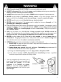
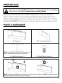
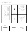
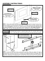
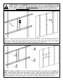
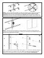
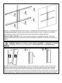
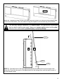
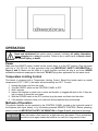
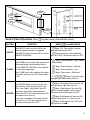
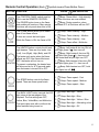
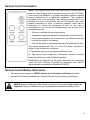
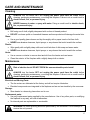
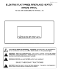
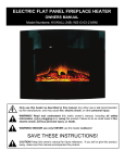
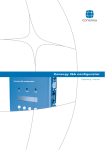
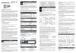
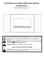
ELECTRIC FLAT PANEL FIREPLACE HEATER OWNERS MANUAL Models: EF27B / SHWALL-35 Only use this heater as described in this manual. Any other use is not recommended by the manufacturer, and may cause fire, electric shock, or other personal injury. WARNING! Read and understand this entire owner’s manual, including all safety information, before plugging in or using this product. Failure to do so could result in fire, electric shock, serious personal injury, or death. WARNING! INDOOR use only! NEVER use this heater outdoors! SAVE THESE INSTRUCTIONS! CAUTION! Keep this owner’s manual for future reference. If you sell or give this product away, make sure this manual accompanies this product. IMPORTANT SAFETY INFORMATION! WARNING ALWAYS keep electric cords, home furnishings, drapes, clothing, papers, or other combustibles at least 3 feet (0.9m) away from the front of this heater, and away from the bottom, sides, and rear of this heater. DO NOT place the heater near a bed because objects such as pillows or blankets can fall off the bed and be ignited by the heater. DO NOT COVER this heater or block the air vents at all. Doing so could cause a fire. AVOID fire or electric shock! NEVER insert or allow any foreign objects to enter the ventilation or exhaust openings of this heater. Prevent Fire! Keep all flammable liquids, like gasoline or paint, away from this heater. This heater produces arcing sparks that could ignite flammable liquids. DO NOT cover this heater in any manner. Doing so could block the air flow and cause the unit to overheat, or could ignite the material covering the heater. NEVER run the power cord under carpet, rugs, runners, or any other covering. Doing so could cause the cord or materials covering the cord to overheat. AVOID FIRE! Regularly inspect all air vents to make sure they are free from dust, lint, or other blockage. Unplug the unit and clean with a vacuum ONLY. DO NOT rinse or get wet. WARNING For residential use only! NOT for commercial use! NEVER use this fireplace for other than its intended purpose. ALWAYS ATTACH WALL MOUNT BRACKET TO WALL AND HANG UNIT BEFORE USE. NEVER USE WHILE THE UNIT IS SITTING ON THE GROUND OR OTHER SURFACE. The wall mount bracket is designed for use ONLY with this product. NEVER use a wall mount bracket from another manufacturer. Use extreme caution if using this heater near children, or where children may be present. NEVER leave this heater unattended. ALWAYS unplug this heater when not in use. This heater is hot when in use. AVOID INJURY! DO NOT TOUCH hot surfaces, or attempt to move this heater while it is hot. ALWAYS turn this heater off before unplugging it from the outlet. AVOID INJURY! Keep the cord from crossing traffic areas to avoid tripping. NEVER modify this fireplace. Doing so could result in personal injury or property damage. Modification of this fireplace completely voids all warranties. Discontinue use if this fireplace malfunctions or is dropped or damaged in any manner. 2 WARNING Risk of electric shock! DO NOT OPEN! No user-serviceable parts inside! ALWAYS disconnect this unit from the power supply before performing any assembly or cleaning, or before relocating the electric fireplace. ALWAYS store this heater in a dry location. NEVER use the fireplace if it has become wet. NEVER use this heater in bathrooms, laundry rooms, or any other location where the heater could fall into a bathtub or pool, become damp or come in contact with water. NEVER hang this unit on a wall directly below an electrical outlet. NEVER operate this heater if the power cord or plug has become damaged, or if the grounding pin is damaged or missing. Place the heater near a wall outlet so an extension cord is not needed. If an extension cord is needed, the gauge of the cord must be at least 14AWG, and the rating must be at least 1875 Watts. NEVER use a smaller gauge cord with a lower rating. Doing so may result in fire or electric shock. ONLY use this heater on a 110~120 Volt 15 Amp grounded circuit. NEVER overload the circuit. If this heater trips the circuit breaker, unplug all other appliances on the same circuit before the next use. Avoid plugging other appliances into the same circuit as this heater. NEVER plug this heater into an outlet that is old, cracked, or has any loose wires or connections. Plugging this heater into a faulty outlet could result in electric arcing within the outlet that could cause the outlet to overheat or catch fire. ALWAYS check your heater cord and plug connections with each use! i) MAKE SURE the plug fits tight in the outlet! Faulty wall outlet connections or loose plugs can cause the outlet to overheat. ii) Heaters draw more current than small appliances. Overheating may occur even if it has not occurred with the use of other appliances. iii) During use check frequently to see if the plug outlet or faceplate is HOT! iv) If the outlet or faceplate is HOT, discontinue use immediately and have a qualified electrician inspect and/or replace the faulty outlets. • The cord supplied with the heater has a plug with two blades (live and neutral) and one round pin (ground). If a 3-slot receptacle is not available, an adapter MUST be used. The adapter MUST be properly grounded to the outlet box (see figure at right). 3 PREPARATION This carton includes a GLASS panel! Always use extreme caution when handling glass. Failure to do so could result in personal injury or property damage. Remove all parts and hardware from the carton and place them on a clean, soft, dry surface. Check to make sure nothing is missing. Dispose of packaging materials properly. Please recycle. Tools (not included): Phillips screwdriver; stud finder; level; tape measure; electric drill; 1/16” drill bit. Concrete walls: DO NOT use these anchors. Consult a professional for proper anchoring methods. PARTS & HARDWARE A – Firebox ( 1 ) B – Front Glass Panel ( 1 ) NOTE: The wall mount bracket (C) is attached to the back of the firebox (A) by two thumb screws (6). C – Wall Mount Bracket ( 1 ) 6 – M5x8 Machine Screws ( 2 ) 6 6 C A NOTE: Unscrew both M5x8 machine screws (6) from the top of the firebox (A). KEEP the machine screws. Remove the wall mount bracket (C) from the firebox. 4 PARTS & HARDWARE Air Vent Panel, Hardware, Remote Control RC – Remote Control ( 1 ) Decorative Stones 2 – M4x8 Machine Screws ( 2 ) WS – White Stones ( set ) RC Battery ( 1 ) CS – Clear Faux Stones ( set ) Wall Hanging Hardware 3 – M5x40 Wood Screws ( 4 ) 4 – M4x30 Drywall Screws ( 4 ) 5 – M15x40 Drywall Anchors ( 4 ) 5 ASSEMBLY INSTRUCTIONS Minimum clearance: 2 inches (5 cm) from edge of glass Wall or other objects at side Wall or other objects at side Minimum clearance: 2 inches (5 cm) from edge of glass Minimum clearance: 11¾ inches (30 cm) from bottom edge Floor or other surface STEP 1. Find a safe location. Minimum clearance on each side must be at least 2 inches (5 cm); minimum clearance from the floor must be at least 11¾ inches (30 cm); minimum clearance from the front must be at least 3 feet (90 cm). Choose a location near an outlet so an extension cord is not required. DO NOT position the unit directly below a power outlet. See Safety Information on pages 2 and 3 for more warnings about placement, installation, and use of this product. NOTICE The wall mount fasteners included with this fireplace are for use ONLY with a wood-framed wall covered in drywall (sheet rock). For concrete walls, cinder blocks, or other wall types, consult a professional for the best attachment methods. Note: The wall mount bracket tabs are on the upper arms and the hooks are on the lower arms. Drywall 16” Tab C 16” Hook 16” 16” 16” Studs STEP 2. Locate the wall studs using an electronic stud-finder. Studs are spaced 16” apart as measured from the center of each stud. The holes in the mounting bracket (C) will align with the wall studs. The end of each arm has a set of three holes. Select one set of holes (left, center, or right) when attaching the mounting bracket to the wall. There are also two holes on the center post. 6 AVOID INJURY and DAMAGE! Four screws should be screwed directly into wall studs. If that is not possible, at least two screws must be screwed directly into wall studs, AND four additional screws must also be screwed into the drywall anchors. C STEP 3. Position the wall mount bracket (C) over the wall studs. Level the mounting bracket and mark the four holes with a pencil. Set the wall mount bracket aside. Drill a pilot hole at each marked point using a 1/16” wood drill bit. Make sure each hole goes into a wall stud. 3 3 3 3 STEP 4. Thread one M5x40 wood screw (3) through the bracket, into the pilot hole, and into the stud. Partially tighten. Make sure the bracket is level. Thread the remaining three M5x40 wood screws into the other three holes. Check the alignment and tighten each screw securely with the Phillips screwdriver. Check each screw to make sure it is tight, and that the bracket is secure. 7 4 3 3 4 4 3 3 4 STEP 5. If only one wall stud is available, the wall mount bracket must be secured to the wall with two M5x40 wood screws (3) though the two center post holes AND four M4x30 drywall screws (4) through one other set of bracket holes. DO NOT attach the wall mount bracket to the wall studs with one of the outer sets of holes as the bracket will not be stable. Use the center holes. C STEP 6. Center the wall mount bracket (C) over the wall stud. Level the mounting bracket and mark the two center post holes with a pencil. Mark the four outer holes for the drywall anchors. Set the wall mount bracket aside until STEP 8. 5 5 5 5 STEP 7. Drill pilot holes into the two center marks using a 1/16” wood drill bit. Make sure each pilot hole is drilled directly into a wall stud. Next, use a Phillips screwdriver to screw the four drywall anchors (5) into the drywall until they are flush with the surface. DO NOT OVERTIGHTEN. 8 4 3 4 4 3 4 STEP 8. Thread the two M5x40 wood screws (3) through the center post holes, into the pilot holes, and into the wall stud. Partially tighten. Make sure the bracket is level. Thread the four M4x30 drywall anchor screws (4) through the wall mount bracket and into drywall anchors. DO NOT OVER- TIGHTEN as this may loosen the anchors or damage the drywall. Check the alignment and tighten each screw securely with the Phillips screwdriver. Check that the bracket is secure. ALWAYS unplug this fireplace heater before assembly or cleaning, or before relocating. Failure to do so could result in electric shock, fire, or personal injury. 6 C 6 A STEP 9. With the firebox (A) at an angle, fit the slots in the back of firebox (A) over the hooks on the wall mount bracket, and carefully press the top of the firebox against the wall mount bracket. The slots at the top edge of the firebox should slide over the wall mount bracket tabs. Hold the firebox in place and thread the machine screws (6) through the holes in the firebox and into the wall mount bracket tabs. Tighten both machine screws and make sure the firebox is secure to the wall. 9 WS/CS STEP 10. Arrange the white stones (WS) and clear faux stones (CS) along the inset window ledge at the front of the firebox. Use care when moving the fireplace as the stones may shift positions. The next step requires installation of a GLASS panel! The manufacturer recommends that two adults install the glass panel. Always use extreme caution when handling glass. Failure to do so could result in personal injury or property damage. Hook A B Post Slot STEP 11. Set both hooks of the front glass panel (B) into the slots at the top front edge of the firebox (A). Press the two posts of the glass panel into the locking slots near the lower corners of the front firebox panel. 10 OPERATION Read and understand this entire owner’s manual, including all safety information, before plugging in or using this product. Failure to do so could result in electric shock, fire, serious injury, or death. Power Make sure the ON/OFF switch, located on the control panel, is in the OFF position. Plug the power cord into a 110~120 Volt 15 Amp grounded outlet (see IMPORTANT SAFETY INFORMATION on Pages 2 and 3). Make sure the outlet is in good condition and that the plug is not loose. NEVER exceed the maximum amperage for the circuit. DO NOT plug other appliances into the same circuit. Temperature Limiting Control This heater is equipped with a Temperature Limiting Control. Should the heater reach an unsafe temperature (212°F / 100°C), the heater will automatically turn OFF. To reset: 1. 2. 3. 4. Unplug the power cord from the outlet. Turn the ON/OFF switch on the CONTROL PANEL to OFF. Wait 5 minutes. Inspect the fireplace to make sure no vents are blocked, or clogged with dust or lint. If they are, use a vacuum to clean the vent areas. 5. With the POWER switch in the OFF position, plug the power cord back into the outlet. 6. If the problem continues, have your outlet and wiring inspected by a professional. Methods of Operation This electric fireplace can be operated by the CONTROL PANEL, located on the right side panel of the fireplace (see figure below), or by the battery-powered REMOTE CONTROL. Before operating, please review the IMPORTANT SAFETY INFORMATION on Pages 2 and 3, and heed all warnings. NOTICE When the heater is first turned on, a slight odor may be present. This is normal and should not occur again unless the heater is not used for a long period of time. 11 Control Panel Pilot Lights Flame Effect LED Backlights Control Panel Operation (Each BUTTON ON/OFF FLAME symbol means Press Button Once) FUNCTION The ON/OFF switch must be ON for the flame and heater functions to operate. PRESS and INDICATION 1. Beep. ON. Flame effect, heaters, lights, and fans remain OFF. The ON/OFF switch must be ON to use the 2. During operation, when switched REMOTE CONTROL. from ON to OFF, all functions will turn OFF. 1. Beep. Flame intensity - High. Heater The FLAME button controls the flame effect is now enabled. (lights and blower) and backlight effects. 2. Beep. Flame intensity - Medium. On the REMOTE CONTROL, these effects are controlled separately. 3. Beep. Flame intensity - Low. The FLAME button also enables the heater. 4. Beep. Flame effect - Multicolor. The heater will only work if the flame effect 5. 6. 7. Beeps. Cycles through is ON. backlight effects with flame effect on. The HEATER button controls the left and right heaters. There are four levels: Low (Left), Low (Right), High (Both), and Off. 1. Beep. Left heater & fan turn ON; left pilot light glows ☼●, then turns off. 2. Beep. Right heater & fan turn ON; right pilot light glows ●☼, then turns off. The heater only works when the flame HEATER effects are ON. If the flame effects are OFF, Left heater and left pilot light turn OFF. the heater will not turn on. 3. Beep. Both heaters & fans turn ON; To prevent overheating, the heater fan will both pilot lights glow ☼☼, then turn off. blow cool air for 8-10 seconds each time 4. Beep. Both heaters turn OFF, both the heater is turned ON or OFF. pilot lights turn off ●●. 12 Remote Control Operation (Each BUTTON symbol means Press Button Once) FUNCTION PRESS and INDICATION The CONTROL PANEL switch must be ON to use the REMOTE CONTROL. 1. Beep. Flame effect – High intensity. All other functions are now enabled. The POWER button turns on the flame and enables all functions. Other remote functions will only work when this is ON. 2. Beep. During operation, when switched OFF, all functions will turn OFF. The FLAME button allows you to select one of four flame effects. 1. Beep. Flame intensity - High. 2. Beep. Flame intensity - Medium. 3. Beep. Flame intensity - Low. 4. Beep. Flame effect - Multicolor. It does not control the back lights. While the Power is ON, the flame is ON. The HEATER button controls the left and right heaters. There are four levels: Low (Left), Low (Right), High (Both), and Off. The heater only works when the flame effects are ON. If the flame effects are OFF, the heater will not turn on. To prevent overheating, the heater fans will blow cool air for 8-10 seconds each time the heater is turned ON or OFF. 1. Beep. Left heater & fan turn ON; left pilot light glows ☼, then turns off. 2. Beep. Right heater & fan turn ON; right pilot light glows ☼, then turns off. Left heater and left pilot light turn OFF. 3. Beep. Both heaters & fans turn ON; both pilot lights glow ☼☼, then turn off. 4. Beep. Both heaters turn OFF, both pilot lights turn off. 1. Beep. Flame speed - Fast 2. Beep. Flame speed - Medium 3. Beep. Flame speed – Slow The BACK LIGHT button controls the LED light strips at the rear edges of the fireplace. The five settings are OFF, Yellow, Blue, Yellow/Blue, and Multicolor. 1. Beep. Back light - Yellow 2. Beep. Back light - Blue 3. Beep. Back light - Yellow + Blue The back lights work with or without the other features being turned on. 4. Beep. Back light - Alternating colors 5. Beep. Back light - Off The SPEED button controls the flame speed. There are three speed levels. 13 Remote Control Information NOTE: This equipment has been tested and found to comply with the limits for Class B digital device, pursuant to part 15 of the FCC Rules. These limits are designed to provide reasonable protection against harmful interference in a residential installation. This equipment generates, uses, and can radiate radio frequency energy and, if not installed and used in accordance with the instructions, may cause harmful interference to radio or television reception, which can be determined by turning the equipment off and on, the user is encouraged to try to correct the interference by one or more of the following measures: • Reorient or relocate the receiving antenna. • Increase the separation between the equipment and the receiver. • Connect the equipment into an outlet on a circuit different from that to which the receiver is connected. • Consult the dealer or an experienced radio/TV technician for help. This device complies with Part 15 of the FCC Rules. Operation is subject to the following two conditions: (1) This device may not cause harmful interference, and (2) This device must accept any interference received, including interference that may cause undesired operation. Modifications not approved by the party responsible for compliance could void user’s authority to operate the equipment. This Class B digital apparatus complies with Canadian ICES-003. Remote Control Battery Information • This remote control uses one CR2032 Lithium-ion 3 volt button cell battery (included). • Instructions for battery installation are inside the Remote Control battery compartment. NEVER dispose of batteries in fire. Failure to observe this precaution may result in an explosion. Dispose of batteries at your local hazardous material processing center. 14 CARE AND MAINTENANCE Cleaning ALWAYS turn the heater OFF and unplug the power cord from the outlet before cleaning, performing maintenance, or moving this fireplace. Failure to do so could result in electric shock, fire, or personal injury. NEVER immerse in water or spray with water. Doing so could result in electric shock, fire, or personal injury. Metal: • Buff using a soft cloth, slightly dampened with a citrus oil-based product. • DO NOT use brass polish or household cleaners as these products will damage the metal trim. Glass: • Use a good quality glass cleaner and dry thoroughly with a paper towel or lint-free cloth. • NEVER use abrasive cleansers, liquid sprays, or any cleaner that could scratch the surface. Plastic: • Wipe gently with a slightly damp cloth and a mild solution of dish soap and warm water. • NEVER use abrasive cleansers, liquid sprays, or any cleaner that could scratch the surface. Vents: • Use a vacuum or duster to remove dust and dirt from the heater and vent areas. • Clean the exterior of the fireplace with a slightly damp cloth or duster. Maintenance Risk of electric shock! DO NOT OPEN! No user-serviceable parts inside! ALWAYS turn the heater OFF and unplug the power cord from the outlet before cleaning, performing maintenance, or moving this fireplace. Failure to do so could result in electric shock, fire, or personal injury. Electrical and Moving Parts: • The fan motors are lubricated at the factory and will not require lubrication. • Electrical components are integrated in the fireplace and are not serviceable by the consumer. Storage: • Store heater in a clean dry place when not in use. Replacement parts: • Use only replacement parts supplied by the manufacturer. Use of any other parts, or modifying the fireplace in any way, will void all warranties. • No internal parts are replaceable or serviceable. WARNING! No other servicing should be performed by the consumer. Do not attempt to service the unit yourself. 15 Limited Warranty This warrants to the original purchaser that this product is free from defects in material and workmanship as of the date of purchase and that it will, under normal use and proper care, remain so for one year from the date of purchase. Missing or initially defective parts will be replaced free of charge during the period of this limited warranty. The original dated sales receipt is required for all warranty claims. This warranty does not cover damage which has occurred during transport from the point of purchase to the consumer’s home. This warranty does not cover glass, light bulbs, remote controls, or batteries. This product is for residential use only. Any and all commercial use of this product voids all warranties, and frees the manufacturer from all liability. The following will void this warranty: Damage caused from tampering with, modifying, or altering the fireplace insert in any manner; Damage due to incorrect assembly, improper care, misuse, or abuse; Damage from being used with the wrong power source; Water damage; Damage caused from this insert being used outdoors; Damage caused from this insert being used for excessive periods of time; Damage caused by the insert being used in a commercial application; Damage from use as a primary heat source; Other misuse or abuse not specifically listed herein. This product is not intended to be used as a primary heat source. VENDOR DEVELOPMENT GROUP, INC.(HEREAFTER, VDG), ITS DIRECTORS, OFFICERS, OR AGENTS, WILL NOT BE LIABLE TO THE PURCHASER OR ANY THIRD PARTY, WHETHER IN CONTRACT, IN TORT, OR ON ANY OTHER BASIS, FOR ANY INDIRECT, SPECIAL, PUNITIVE, EXEMPLARY, CONSEQUENTIAL, OR INCIDENTAL LOSS, COST, OR DAMAGE ARISING OUT OF OR IN CONNECTION WITH THE SALE, MAINTENANCE, USE, OR INABILITY TO USE THIS PRODUCT, EVEN IF VDG, OR ITS DIRECTORS, OFFICERS, OR AGENTS HAVE BEEN ADVISED OF THE POSSIBILITY OF SUCH LOSSES, COSTS OR DAMAGES, OR IF SUCH LOSSES, COSTS, OR DAMAGES ARE FORESEEABLE. IN NO EVENT WILL VDG, OR ITS OFFICERS, DIRECTORS, OR AGENTS BE LIABLE FOR ANY DIRECT LOSSES, COSTS, OR DAMAGES THAT EXCEED THE PURCHASE PRICE OF THE PRODUCT. Some jurisdictions do not allow the exclusion or limitation of incidental or consequential damages, so the above limitation or exclusion may not apply to the purchaser. This limited warranty gives you specific legal rights, and you may also have other rights which vary from jurisdiction to jurisdiction. Thank you for purchasing this Electric Fireplace! If you need assistance with assembly, have questions about the use of this product, or have missing or defective parts, please e-mail us at [email protected] Or, call us toll-free (M-F 8:30 AM to 4:30 PM Central Standard Time) at 1-866-561-0731 Vendor Development Group, Inc. Minneapolis, MN 55401 Made in China Printed in China, July, 2011 16