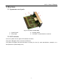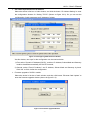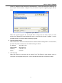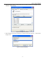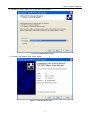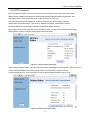
1
USER’S MANUAL
ETHERNET INTERFACE MODULE(EIM)
JK-E01
Shandong New Beiyang Information Technology Co., Ltd.
JK-E01 User’s Manual
Declaration
Information in this document is subject to change without notice. Shandong New Beiyang Information
Technology Co., Ltd.(hereinafter as SNBC) reserve the right to improve products as new technology,
components, software, and firmware become available. If users need the further data about these
products, please feel free to contact with SNBC or our agents.
No part of this document may be reproduced or transmitted in any form or by any means, electronic or
mechanical, for any purpose without written permission of SNBC.
Copyright
Copyright © 2007 by SNBC
Printed in China
Version: 2.00
All rights reserved
Trademarks
SNBC registered trademarks:
Marks means
Warning: Items shall be strictly followed to avoid injury or damage to body and devices.
Caution: Items with important information and prompts for operating the printer.
The quality control system of SNBC has been approved by the following certification.
(DNV)ISO9001:2000
The environmental control system of SNBC has been approved of the following certification.
(DNV)ISO14001:2004
Safety Instructions
Before installing and using the printer, please read the following items carefully.
1) Please comply to the cautions in Printer User’s Manual, as this interface module belongs to a part of
printer.
2) Don’t connect phone line with the communication interface of JK-E01 Ethernet Interface Module
(JK-E01 EIM).
3) Keep this manual carefully in hand for usage and reference.
-1-
JK-E01 User’s Manual
Contents
1 Overview ..............................................................................................................................................1
1.1 Product Description.........................................................................................................................1
1.2 Main Features .................................................................................................................................1
2 Technical parameters ..........................................................................................................................2
3 Structure ..............................................................................................................................................3
3.1 Appearance and parts.....................................................................................................................3
3.2 LED Indicator ..................................................................................................................................3
4 Installation of JK-E01 module ............................................................................................................4
4.1 Unpacking .......................................................................................................................................4
4.2 Connect JK-E01 Module .................................................................................................................4
5 Usage of JK-E01 Module.....................................................................................................................5
5.1 Print Self-test Page .........................................................................................................................5
5.2 Device Search and Parameter Configuration..................................................................................5
5.3 Implementation of Printing Functions..............................................................................................9
5.4 Program Upgrade .........................................................................................................................13
5.5 Status Back ...................................................................................................................................13
5.6 HTTP functions .............................................................................................................................15
6 Interface Signal..................................................................................................................................17
6.1 Parameter of Network Interface Socket ........................................................................................17
6.2 Electric Characteristic ...................................................................................................................17
-2-
JK-E01 User’s Manual
1 Overview
1.1 Product Description
JK-E01 EIM operates with SNBC printer to implement Ethernet communication functions, such as
10BASE-T Ethernet communication, 9100 Port printing, printer status back, configuration of interface
module and maintenance.
1.2 Main Features
¾ Features
z 10 BASE-T Communication
z Frame type compatible with Ethernet II
z LEDs display web connecting status and data transmitting status.
z Support Port 9100 printing
z Support status back
z Support parameter configuration
z Support firmware upgrade online
z Support printer status inquiry and interface module maintenance
¾ Supported Protocols
z IP
z ARP
z ICMP
z TCP
z UDP
z DHCP
z TFTP
z HTTP
-1-
JK-E01 User’s Manual
2 Technical parameters
Items
Parameter
Power Source
Use the power offered by host printing processes, average current is 310mA
Communication interface
Match with 10BASE-T of IEEE802.3
Operating temperature and humidity
5~45℃,20~80%RH (without condensation)
Storage temperature and humidity
-40~55℃,≤93%RH(40℃)
Weight
60g
Overall Dimension
78.5 (W)×62.7 (L)×26 (H)mm
Table 2.1 Technical parameters of JK-E01 EIM
-2-
JK-E01 User’s Manual
3 Structure
3.1 Appearance and parts
Fig.3.1.1 Top View of JK-E01 EIM
1----Control board
2----Interface baffle
3----JP3 jumper
4----10-BASE-T communication connector
3.2 LED Indicator
It has one yellow and one green LED indicator as below:
The green LED lights when it connects to Ethernet.
The yellow LED lights until there has been no activity for 6 ms (i.e. each transmission, reception, or a
fault produces a pulse lasting 6 ms)
-3-
JK-E01 User’s Manual
4 Installation of JK-E01 module
4.1 Unpacking
When opening packages, check if parts are short or damaged according to the Packing List. In case of
shortage or damage, please contact with SNBC or our distributors.
4.2 Connect JK-E01 Module
JK-E01 module shown as figure 4.2.1 shall be connected with communication interface of printer, which
could be fixed with screws. Network cable is connected into 10BASE-T communication connector.
Figure 4.2.1 JK-E01 Module Assembly
-4-
JK-E01 User’s Manual
5 Usage of JK-E01 Module
5.1 Print Self-test Page
After JK-E01 module is installed, refer to printer user’s manual to print a self-test page. The self-test
information relative to Ethernet Interface is as below:
Figure 5.1.1 Self-test Page Information
Note:
Interface Type: the type is for Ethernet
Interface Firmware: shows the firmware version of interface module
IP Address: shows the currently used IP Address of interface module
MAC Address: shows hardware MAC Address of interface module
SUBNET Mask
GATEWAY
DHCP: shows if web-configuring parameters as IP Address are obtained by DHCP. Disabled means
not in use of DHCP, and Enabled means in use of DHCP mode.
5.2 Device Search and Parameter Configuration
The tool of NetWinConfig.exe could search and connect to JK-E01 module in network and configure it
with web parameter.
Before running the software, SUBNET Mask of host machine set should consist with that of Ethernet
interface module. To ensure host PC and interface module under one SUBNET, IP Address of host PC is
set under same SUBNET address.
Notice:
In case of configuring JK-E01 module with web parameter in use of configuration tools, if many network
devices with same IP Address are connected under one SUBNET at same time(for example, many
interface modules all use default settings), the communication could not work normally due to a collision
existing in IP Address. Therefore, when JK-E01 module with default settings is configured with network
parameter, for each time only one Ethernet interface device could be connected, and you should ensure
that the configured IP Address is different. To avoid the collision between the IP Addresses of interface
module and other host PC, interface module and host PC for configuration should be set in a separated
network, for example, they could be connected to a separated hub or mutual web line for single device
(The joint line at two ends of web line can connect data receiving and transmitting signals across, host
-5-
JK-E01 User’s Manual
PC and interface module can be connected directly.
The detailed usage of the software and module configuration is referred to the description documents as
below:
Run “NetWinConfig.exe” and it will show the main window of configuration/upgrade (shown as figure
5.2.1).
Figure 5.2.1 Configuration Tool Window
¾
Search network device function
Click the button “Search Printer” in main window, and later find all printers in use of Ethernet
JK-E01 Module under same subnet, which are shown in list box for user’s configuration,
including:
Name of printer, MAC Address, IP Address, Gateway Address, Subnet Mask, DHCP
enable/disable and firmware version of JK-E01 module.
-6-
JK-E01 User’s Manual
¾
Set network parameters as IP Address
Select the device in list box of main window, and click the button “IP Address Setting” to enter
the configuration window for “Setting TCP/IP” (Shown as figure 5.2.2). So you can set the
configuration of web parameters as IP Address of printer.
Figure 5.2.2 Configuring Web Parameter Window
Via this window, two ways for the configuration can be used as below:
1) First: select “Dynamic IP Address (DHCP)”, and then IP Address, Subnet Mask and Gateway
could be obtained automatically via DHCP Protocols;
2) Second: select “Fixed IP Address”, set IP Address, Subnet Mask and Gateway by hand.
Click “OK” to finish it after the configuration.
¾
Firmware upgrade of JK-E01 module
Select the device in list box of main window, and then click button “Ethernet Card Update” to
enter the firmware upgrade window (shown as figure 5.2.3).
Figure 5.2.3 Firmware Upgrade Window
-7-
JK-E01 User’s Manual
Check if IP Address is same with that of selected device. If same click the button “Select File” to
enter “open” window (shown as figure 5.2.4), and select to open the upgrade program file as
below:
Figure 5.4.2 “open” Window
Select the upgrade program file, and double click or single click the button “Open” to finish
opening the upgrade file and obtaining file name, at last click the button “Update” to return
upgrade window and execute date-transmitting upgrade.
¾
Recover default settings
Select the device in list box and click the button “Restore Default Configuration” in main window,
and then the printer could recover the default settings as below:
¾
IP Address:
192.168.10.251
Subnet Mask:
255.255.254.0
Gateway:
192.168.11.53
DHCP:
Disabled
Print test page
Select the printer in list box and click the button “Print Test Page” in main window, then you
could print out test pages with printer, of which include the parameter of interface module
-8-
JK-E01 User’s Manual
5.3 Implementation of Printing Functions
Printer driver should be installed according to the instruction of the driver in printer user’s manual and
selects serial interface. After installation, the port of printer driver is reset at network port. The followings
show how to configure network port with BTP-2002CP printer under WindowsXP system:
¾ Click the picture of BTP-2002CP printer installed, open the property window of printer (shown as
figure 5.3.1)
Figure 5.3.1 Property Window of Printer
-9-
JK-E01 User’s Manual
¾ Select the property column of “Ports” (shown as 5.3.2). Now no TCP/IP Port is installed, first click
“Add Port….” button as below:
Figure 5.3.2 Property Column Window
¾ Select “Standard TCP/IP Port” in the list box of “Printer Port” and click “New Port….” button (shown
as figure 5.3.3).
Figure 5.3.3 Printer Ports Window
- 10 -
JK-E01 User’s Manual
¾ Click “Next ” Button (shown as figure 5.3.4)
Figure 5.3.4 Add TCP/IP Printer Port
¾ Fill with “printer name or IP Address” in corresponding editing column as figure 5.3.5, of which the
content is same with self-test page of printer, and then click “Next” Button.
Figure 5.3.5 Add TCP/IP Print Port
- 11 -
JK-E01 User’s Manual
¾ Default the content (figure 5.3.6) and click “Next” Button.
Figure 5.3.6 Add TCP/IP Print Port
¾ To end the port adding, click “Finish” Button.
Figure 5.3.7 Add TCP/IP Print Port
- 12 -
JK-E01 User’s Manual
¾ Select new TCP/IP Port and click “Apply”, then “OK”, and TCP/IP Port configuration is finished
(shown as figure 5.3.8).
Figure 5.3.8 PORT Property Column Window
5.4 Program Upgrade
JK-E01 module supports firmware upgrade, which depends on TFTP Protocol to function. In use of the
tool “NetWinConfig.exe” the firmware upgrade can be executed, or any TFTP client tool also can
transmit the firmware-upgrading file to Port 69 of the interface module for upgrade.
For example: operate firmware upgrade as follows in use of TFTP command attached with its own
Windows2000 System.
C:>tftp –i 192.168.10.251 put filename. JK
Among which –i presents to transmit documents in binary mode; 192.168.10.251 is IP Address of the
Interface Module to be upgraded; filename. JK is a firmware to be upgraded.
When upgrading, the firmware provided by SNBC must be used. If the upgrade fails (as printer is shut off
during the upgrade), take off J3 jumper and then restart the printer after closing it. At this moment
interface module enter BOOTLOADER mode, you can upgrade the firmware of interface module again.
After the upgrade is successful, the printer is reset automatically and the upgrade is effective.
5.5 Status Back
The back status of printer could be obtained via the status monitor routine offered by SNBC. This course
provides source code for users which conduct them how to use DLL function, and execute enquiry
printing status and transmit printing data for printer via programming itself.
- 13 -
JK-E01 User’s Manual
The usage of status monitor routine is referred to below instruction:
Run “NetPrinterStatus.exe”, then Status Monitor Window comes out (shown as figure 5.5.1):
Figure 5.5.1 Status Enquiry Window
To set IP Address of interface module of printer, click the button “Print Test” to connect printer and
transmit printing data, and then close the connection of three items. Click “Printer Status” button to enter
Status Monitor Window。Click the button “Start Monitor” and start to monitor the status of printer. The
normal status of printer is shown as figure 5.5.2:
Figure 5.5.2 Normal Status Display
If the status is changed, the interface indicator shall show red. Click the button “Stop Monitor” to stop
status monitor, and click the button “Return” back to main window.
- 14 -
JK-E01 User’s Manual
5.6 HTTP functions
JK-E01 module can offer HTTP service that it uses the browser at the host to show the printer
status and the module status based on WEB and proceeds interface module configuration and
test-page printing. The port number used for this service is 80 TCP port.
The user should first get IP address of JK-E01 module via the self-test page or special
configuration tool when using it. Then input IP address in browser address list to inquire
the printer status and the interface module via WEB with details as below:
Start Internet browser and input the printer IP address, then you can see the interface status page.
Click “Refresh” button to refresh current status shown as below:
Figure 5.6.1 Show interface status page
When clicking “Printer Status”, you can check the printer status page connecting with JK-E01 module. If
it shows abnormal status, red words shall be shown. Click “Refresh” button to refresh
current status and click “ Print Test Page” to print a self-test page shown as Figure 5.6.2:
Figure 5.6.2 Show printer status’ page
- 15 -
JK-E01 User’s Manual
Click “Configure Interface” to enter configuring interface page. This page shall provide two configuration
modes: 1. Select “Dynamic IP Address (DHCP) and get IP Address, Subnet Mask and Gateway Address
automatically via DHCP protocol. After the modification, click “Save” to save the settings, also can click
“Restore Defaults” button to recover factory defaults. When finishing the configuration, you need to
restart the printer to effect new settings. For restarting the printer, click “Reset” button at the left or turn
on/off the printer power. The configuration page is shown as Figure 5.6.3:
Figure 5.6.3 Interface configuration page
- 16 -
JK-E01 User’s Manual
6 Interface Signal
6.1 Parameter of Network Interface Socket
It meets with 10BASE-T Standard of IEEE802.3
Figure Socket of JK-E01 EIM
Pin
Signal Name
Description
1
TX+
Data transmission +
2
TX-
Data transmission -
3
RX+
Data receive+
4
NC
Reserve
5
NC
Reserve
6
RX-
Data Receive-
7
NC
Reserve
8
NC
Reserve
Figure 6.1.1 Pin list of Interface Module
6.2 Electric Characteristic
¾ Output signal
Effective differential voltage is above 450Mv, and peak voltage is less than 13V;
Common-mode AC voltage is less than 2.5V.
¾ Input signal
The signal is available when differential voltage is above 160mV.
- 17 -