1
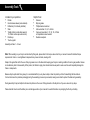
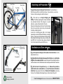
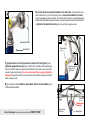
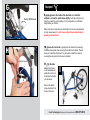
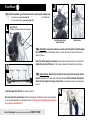
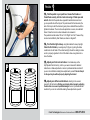
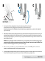
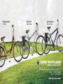
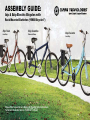
ASSEMBLY GUIDE: Izip & Ezip Electric Bicycles with Rack-Mounted Batteries (“RMB Bicycles”) Ezip Trailz Low Step Ezip Coastline Diamond Frame Please Refer to your Owner’s Manual for Detailed Setup Instructions Technical & Customer Service: 1-800-377-4532 Izip Via Lento Low Step Assembly Tools Included in your parts box: Helpful Tools: • • • • • • • • Pedals Quick release skewer (some models) Reflectors (if not already installed) Stem Toolkit (4+5mm combo Allen wrench, 13+15mm combo open-end wrench) Rack keys Touch-up paint • • • • • Scissors Bicycle grease Phillips-head screwdriver Allen wrenches: 2.5, 4, 5, & 6mm Open-end wrenches: 9, 10, 14, 15, & 17mm or adjustable crescent wrench Needle-nose pliers Assembly will take 1 - 2 hours Note: When working on your bicycle as instructed by this guide, please refer to the torque values chart in your owner’s manual for detailed torque requirements. Under- or over-tightened components may loosen or break, causing a fall. Steps in this guide that call for the use of bicycle grease do so in the interest of keeping your bicycle in working condition for as long as possible. Grease is not absolutely vital to the assembly of this product, but failure to apply it as directed could cause parts to seize over time and irreparably damage the frame or components. Because bicycle parts tend to be greasy, it is recommended that you lay down a tarp or sheet to protect your floor if assembling the bike indoors. It is best to remove the protective packaging during the assembly process only as needed, leaving some intact to protect the bike during assembly. During assembly it may be helpful to reference the photos on the cover of this guide and on the bicycle box if you are unsure of any steps. Please take the time to read the battery care and storage section of your manual for useful information on prolonging the life of your battery. A Seat Tube Head tube Top Tube 1. Carefully remove the bicycle from the box. You should have a friend help you with this, as the bike is heavy. If you are alone, you can lay the box on its side and gently slide the bike out. Down Tube Chainstay C Seatstay 2. At this point you can begin charging your battery. The battery is packaged in a brown cardboard Fork Izip stem Unpacking and Preparation Wedge bolt (top of stem) box underneath the bike. The charger is in a small white box, usually rubber-banded to the rack. Recommend charge time is 6-8 hours. Plug the charger first into the wall outlet, then into the port underneath the battery handle (figure B). A solid red or blinking green light on the charger (depending on model) indicates the battery is charging properly. A solid green light indicates that the charger has entered trickle charge mode, and your battery is at least 80% full. For maximum range, please charge for the full recommended time period (6-8 hours). B Handlebars and Stem 3. Cut the zip-ties holding the front wheel to the bike frame. Set the wheel aside for now. Faceplate 4. Rotate the fork so the brake faces away from the frame, then rest the bike upright on its rear wheel and fork, as shown in figure A. When rotating the fork, be sure the cables run in front of the frame and do not wrap around the fork or head tube. Protective cap (remove and discard) Ezip stem 5. Find the stem in the parts box (figure C). Remove the protective caps from the stem and head tube, then insert the stem into the bike’s head tube facing away from the frame. Remove the faceplate by removing the two or four faceplate bolts (depending on model) shown in figure D. Please recycle packaging materials! Currie Technologies Technical and Customer Service 1-800-377-4532 D 6. Cut the zip-ties securing the handlebar to the bike frame, arrange the brake and shifter cables so they run in front of the bicycle, then clamp the handlebars to the stem using the faceplate as shown in photo E. The bars should be rotated to a comfortable gripping position with comfortable access to the brake levers, and centered around the stem. Be sure to tighten the faceplate bolts evenly so the top and bottom gaps are equal. Faceplate Bolts Head tube E Wedge Bolt (top) 7. Align the stem so it is facing forward in relation to the fork (figure F), then tighten the wedge bolt securely. Be sure that the fork is rotated with the brakes facing Equal faceplate gaps & bolt tightness forward, and that no cables are tangled around it! Refer to the photos on the cover of this manual for proper cable routing. It is extremely important that you properly tighten the wedge bolt. Leaving this bolt too loose can result in the handlebars turning away from the wheel, causing a crash. 8. If not already installed, attach the square white reflector to the handlebar using a Phillips-head screwdriver. F Shifter (left side) Currie Technologies Technical and Customer Service 1-800-377-4532 Stem in line with fork (Top View) Throttle (right side) Brakes face forward! Wedge Bolt G Seatpost 9. Apply grease to the inside of the seat tube, then insert the Swing QR Closed seatpost and close the quick release tightly. It will help during the next steps if you lower the seat completely; it can be adjusted to a comfortable height before your first ride. Refer to the owner’s manual for more information on the use and adjustment of quick release levers. It is vital to your safety that you understand and properly secure this lever! H 10. Release the front brake by pulling back the rubber boot, squeezing the brake arms together, then removing the noodle from its holder. This will allow you to install the front wheel. You will need to reattach the brake by reversing this step once the front wheel is installed. Brake Noodle 11. Flip the bike over so that it rests on its handlebars and saddle. Be careful not to damage the throttle or brake levers. Boot I Remove the plastic dropout protector from the end of the fork. Currie Technologies Technical and Customer Service 1-800-377-4532 Front Wheel 12. Determine whether your front wheel uses a solid or quick release axle • • L J K (see photo J/K). For solid axles, proceed to step 12a. For quick release axles, proceed to step 12b. Solid Axle Safety washer hooks into dropout Solid axle with safety washer and nut Quick release 12a. Solid Axle: Loosen the axle nuts on each side of the wheel. Insert the wheel into the fork, making sure the safety washer on each side is to the outside of the fork, as shown in photo L. M End Nut Spring Skewer Orient the safety washers as shown so their hooks insert into the holes in the fork, then tighten the axle nuts firmly with a 15mm open end wrench (included in your parts box). Spring 12b. Quick Release: Remove the end nut and one spring from the quick release skewer, taking care not to lose either of the small springs. Push the skewer through the front hub, then replace the spring and end nut. Leave the nut loose for now, about two turns in. Insert the wheel into the fork, as shown in photo N. Securely close the quick release. Refer to the appendix of this document for more information on the use and adjustment of quick release levers. It is vital to your safety that you understand and properly secure this lever! Currie Technologies Technical and Customer Service 1-800-377-4532 N O Pedals Tighten 13. Find the pedals in your parts box. Grease the threads and thread them securely into the crank arms using a 15mm open-end wrench. Note that the pedals have opposite thread directions and must go on a specific side of the bicycle. The pedal meant for the drive-side (the side of the bicycle with the chain and gears) has a standard thread, which is tightened clockwise. The non-drive-side pedal has a reverse, non-standard thread. It must be turned counter-clockwise to be screwed in. The pedals should be marked ‘R’ and ‘L’ for “Right” and “Left,” however they can also be identified by their threads, as shown in diagram P. 14. Turn the bike right-side-up, using the kickstand to keep it upright. Close the front brake by reversing step 10 (figure H), pulling the brake noodle back into its holder. If the cable feels tight, check the cabling to make sure it is properly organized in front of the bike to allow enough slack to reclose the brake. P 15. Adjust your front and rear brakes. Your brakes may not be fully adjusted from the factory; refer to your owner’s manual for detailed instructions on brake adjustment or consult a professional bike mechanic if you are not comfortable making these adjustments yourself. Do not attempt to ride your bicycle without properly adjusting the brakes! 16. Adjust your shifters and derailleurs, referring to the owner’s manual for full instructions. Riding your bicycle without properly adjusting the drivetrain can cause irreparable damage! Consult a professional bike mechanic if you are not comfortable making these adjustments yourself. Currie Technologies Technical and Customer Service 1-800-377-4532 Q Battery Installation: Your electric bicycle comes with a 24 volt sealed lead-acid (SLA) battery. To install the battery, simply slide it into the rear rack (as shown in figure Q, Currie logo facing outward) making sure you first remove the rubber terminal cover if present. This type of battery does not have a memory, and riding on a partial charge will not harm the battery in any way. Recharge time for this battery is 6-8 hours to reach a full charge. Locking: Locks are included with the RMB rack to hold the batteries in place when riding. It is recommended that the battery pack be locked whenever you are riding in order to maintain a strong connection. After sliding a battery pack into place, lock it with one of the included keys (usually in the parts box or rubber-banded to the rack), making sure the lock cylinder fully engages into the battery case. All keys included with your bicycle are identical. Operation To turn your bicycle on: Ezip RMB Bicycles & Izip RMB bicycles prior to 2010: Flip the three-position battery selector switch, located on the rack behind the rear reflector, to the side corresponding to the attached battery you wish to use. This turns the bicycle on, indicated by the glowing lights on the throttle. To turn the bike off, flip the battery selector switch to the neutral center position. Izip RMB Bicycles: Flip the two-position battery selector switch, located on the rack behind the rear reflector, to the side corresponding to the attached battery you wish to use. Once you have selected your battery, press the “ON/OFF” switch next to the throttle on the handlebars (as shown in photo S1) to turn the bike on. To turn the bike off, simply press “ON/ OFF” again; there is no need to change the position of the battery selector switch. PAS/TAG System: Using the “PAS/TAG” selector button on the throttle, you can switch between PAS (Pedal Assist) and TAG (Twist And Go) modes. TAG mode uses a straight throttle system; motor power is directly controlled by the throttle on your handlebars. When the bike is switched to PAS mode, a sensor in the drivetrain is activated, allowing the motor to automatically run at up to 50% power when it senses pedaling. This PAS mode helps to maximize range as it only activates the motor when the rider is pedaling. Currie Technologies Technical and Customer Service 1-800-377-4532 R Izip: ON/ON (Battery selector) Ezip: ON/OFF/ON (Power and selection) S ON/OFF Button PAS/TAG SELECTOR 1 PAS/TAG SELECTOR 2 For Izip RMB Bicycles Only For Ezip RMB Bicycles Only Before your first ride... • • • • Remove all remaining packaging on the bike, including the plastic covers on the outside of the wheels Check the operation of your front and rear brakes by pushing the bike forward and operating the brake levers. Check the tightness of all nuts and bolts, especially the front and rear wheel nuts, the stem bolts, and the bolts securing the brake levers and shifters to the handlebars. Make sure the stem’s wedge bolt is tight. Check that it is tightened properly by standing over the front wheel, holding it with your thighs, then trying to turn the handlebars. If the handlebars can be turned independently of the wheel, the wedge bolt must be tightened further. • Make sure your front wheel is secure in the frame. Refer to the quick release section in the owner’s manual for detailed instructions on using • Make sure your tires are filled to the pressure recommended on the sidewall. Over- or under-inflated tires can blow off the rim and cause • quick releases. a fall. We recommend using a bicycle pump with pressure gauge. Test power: lean the bike on its kickstand, raising the rear wheel off the ground. When the bike is powered on (indicated by the throttle lights) you can test system power by twisting the throttle in TAG mode and watching the rear wheel. Refer to the troubleshooting chart on this page for assistance if the bike will not power on. Refer to owner’s manual for detailed troubleshooting chart Bike won’t turn on (no lights on throttle) Battery selector flipped to wrong side Battery not seated properly against rack terminals Need to press handlebar ON/OFF switch Battery not charged Throttle lights work, but motor will not run Bike may be in Pedal Assist mode. Press the red button on the throttle to change to Twist-and-Go mode. Brakes rub when riding Re-adjust brakes, referring to owner’s manual Gears/chain make clicking or grinding noises while riding Re-adjust drivetrain, referring to owner’s manual Can someone help me with...? Call the Currie Technologies technical and customer service department at 1-800-377-4532 Currie Technologies Technical and Customer Service 1-800-377-4532 Appendix: Quick Release Levers Many Izip and Ezip bicycle models use quick release (QR) levers to facilitate common tasks such as front wheel removal and seat height adjustment. When properly adjusted, quick release levers are both safe and convenient, but you must understand and apply the correct technique to adjust them properly before riding your bicycle to prevent serious injury or death from a fall. Quick release levers use a cam action to clamp the wheel or other components in place. Because of their adjustable nature, it is critical that you understand how they work, how to use them properly, and how much force you need to apply to secure them. Warning: The full force of the cam action is needed to clamp the wheel securely. Holding the nut with one hand and turning the lever like a wing nut is NOT a safe or effective way to close a quick release and will not clamp the wheel or other components safely. QUICK RELEASE USAGE Riding with an improperly adjusted wheel quick release can allow the wheel to wobble or fall off the bicycle, which can cause serious injury or death. Therefore, it is essential that you: 1. Ask your dealer or a local bike shop to help you make sure you know how to install and remove your wheels safely. 2. Understand and apply the correct technique for clamping your wheel in place with a quick release. 3. Each time, before you ride the bike, check that the wheel is securely clamped. Installing a quick release front wheel 1. Remove the tension adjusting nut and one of the small springs, then slide the quick release skewer through the hub. If your bicycle has a disc brake, insert the skewer starting on the side with the brake rotor. 2. Replace the spring and tension adjusting nut (figure a). The wheel hub is clamped in place by the force of the quick release cam pushing against one dropout and pulling the tension adjusting nut, by way of the skewer, against the other dropout. The amount of clamping force is controlled by the tension adjusting nut. Turning the tension adjusting nut clockwise while keeping the cam lever from rotating increases clamping force; turning it counterclockwise while keeping the cam lever from rotating reduces clamping force. Less than half a turn of the tension adjusting nut can make the difference between safe clamping force and unsafe clamping force. Currie Technologies Technical and Customer Service 1-800-377-4532 a Tension adjusting nut c b Springs open closed 1. If your bicycle has rim brakes, disengage them to increase the clearance between the tire and brake pads. Install the wheel into the dropouts, making sure the quick release lever is on the left side of the bicycle. Holding the quick release lever in the OPEN position with one hand, tighten the tension adjusting nut with your other hand until it is finger tight against the fork dropout. 2. While pushing the wheel firmly to the top of the slots in the fork dropouts, and at the same time centering the wheel rim in the fork, move the quickrelease lever upwards and swing it into the CLOSED position (fig b & c) The lever should now be parallel to the fork blade and curved toward the wheel. To apply enough clamping force, you should have to wrap your fingers around the fork blade for leverage, and the lever should leave a clear imprint in the palm of your hand. WARNING: Securely clamping the wheel takes considerable force. If you can fully close the quick release without wrapping your fingers around the fork blade for leverage, and the lever does not leave a clear imprint in the palm of your hand, the tension is insufficient. Open the lever; turn the tension adjusting nut clockwise a quarter turn; then try again. 3. If the lever cannot be pushed all the way to a position parallel to the fork blade, return the lever to the OPEN position. Then turn the tension adjusting nut counterclockwise one-quarter turn and try tightening the lever again. 4. Re-engage the brake quick-release mechanism to restore correct brake pad-to-rim clearance; spin the wheel to make sure that it is centered in the frame and clears the brake pads; then squeeze the brake lever and make sure that the brakes are operating correctly. Currie Technologies Technical and Customer Service 1-800-377-4532 Ezip Coastline Low Step Ezip Trailz Diamond Frame Izip Via Lento Diamond Frame 9453 Owensmouth Ave, Chatsworth, CA 91311 Phone: +1 800.377.4532 Fax: +1 818.734.8199 www.currietech.com