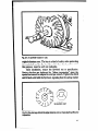
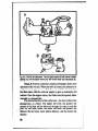
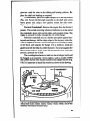
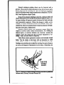
1
MICROFICHE
REFERENCE
LIBBRARY
4 project of Volunteers
in Asia
Bow to Repair Briggs
5;~: Paul
h Stratton
Encti
Dempsey
Sub1 ished
by:
TAB Books
Blue Ridge Summit
Pennsylvania 17214
Paper copies
USA
are $ 4.95.
Available
from:
TAB Books
Blue Ridge Summit
Pennsylvania 17214
Reproduced by permission
USA
of TAB Books.
Reproduction
of this microfiche
document in any
form is subject
to the same restrictions
as those
of the original
document.
TAB
BOOKS/No.
1087
$4.95
A step-by-stepguide to understanding,tuning, adjusting, repairing, and overhauling.
By Paul Dempsey
Now you can maintain and repair any Briggs & Stratton small
gasoline engine! Everything you need to know is here in do-iiyourselfer’s language, from simple tune-up and carburetor reg.airs to
the serious business of replacing main bearings and resizing cylinder
bores.
You’ll quickly see how an engine works, how each systemignition, fuel, lubrication, and cooling-contrib&e
to the proper operation of an engine. And where possib!e. adjustment and repair procedures appear in step-by-step order.
Special emphasis is given to unique Briggs & Stratton features:
the Pulsa- and Vacu-Jet carburetors, the starter clutch, and the
vertical-pull starter. And, while Briggs & Stratton engines are workhorses, intended to perform with maximum reliability, they can be
made into screamers. Indeed, Briggs & Stratton dominates four-cycle
go-cart racing, and given the right preparation, run with the better two
cycles. For readers who are interested, material is included on hop-up
techniques.
Paul Dempsey is a master mechanic and veteran engine/
automotive journalist. He is the author of manjl of the related titles
appearing below.
(No. 1067-$7.95 paper; $12.95 hard)
How To Repair Small Gasoline Engines-2nd
Edition
(No. 91746.95 paper; $11.95 hard)
Do-It-Yourselfer’s Guide to Chainsaw Use & Repair
(No. 89245.95 paper; $8.95 hard)
l%e Complete Handbook of Lawnmower Repair
(No. 76747.95
paper)
Complete Guide to Outboard Motor Service & Repair
(No. 727-$6.95 paper: $9.95 hard)
Motorcycfe Repair Handbook
(No. 769-$6.95 paper; $9.95 hard)
The Complete Snowmobile Repair Handbook
(No. 70646.95 paper; $9.95 hard)
Moped Repair Handbook
(No. 97646.95
paper; $9.95 hard)
How to Repair Diesel Engines
(No. 81745.95
paper; $9.95 hard)
How to Convert Your Car, Van, or Pickup lo Diesel
(NO. 96~$6.95
paper; $9.95 hardj
How to Repair Lift Trucks
(No. 967419.95
SW-BY-Step
hard)
Guide TO Ford/Mercury/Lincoln
(No. 948-$6.95 paper; $9.95 hard)
Step-By-Step Guide to Engine Maintenance/Repair:
(NO. 84845.95
Engine Maintenance/Repair
The Chrysler
Family
paper: $8.95 hard)
-SO PUBLlSHERS OF MODERN AUTOMOTIVE SERIES s MODERN AIRCRAFT SERIE:
LUE RIOGE~SUMMIT. PA. 17214
end for FREE TAB Catalog
describing over 600 current titles in print.
Other TAB books by tbe author:
No. 967Hour to Repair Li# Tnccks
No. 846 Tke Biqycle#s Bible
No. 946 Step-3y-Step Guide to Ford/Mercu~/Lincoln Engine
Maintenance Repair
No. 769 Motor&? Repair Handbook
No. 917Htno to Repair Small Gasoline Engines-2nd Edition
No. 727 Compbte G&e to Outboard Motor Sepvice& Repair
No. 767CompleteHandbook of LawnmowevRepair
No. 651 Tke CompleteMini&ke Handbook
No. 705 Tke Co,apleteSntn+mobileRepair Handbook
No. 817 How to Repair Diesel Engines
No. 668 Modem Guide to Auto Tuneup & Emission Cont~uiSe&tirs
No. 849 Vega
No. 966 How to Convert Your Car, Van, IX Pickup to Diesel
No. 976 Moped Repair Handbook
A
By Paul Dempsey
I
BLUE
RIDGE
SUMMIT,
PA.
17214
FIRST EDITION
FIRST PRINTING-OCTOBER 1978
Copyright 0 1970 by TAB WOKS
Printed in the United States of America
Reproduction or publication of the content in any manner, without express
permission of the publisher, is prohibited. No liability is assumed with respect
to the use of the information herein.
Library of Congnss Cataloging in Publication Data (Revised)
Dempsey, Paul.
How to repair Bnggs & Stratton engines.
includes index.
1. lntemat combustion engines, Spark ignition-Maintanance
and repair. I. Tale.
78-10470
TJK789D43
621.434’028
ISBN o-8306-9873-6
ISBN 0-8306-1087-l pbk.
Cover courtesy of Srfggs & Stratton.
This book describesrepair and maintenanceprocedures for all current and many obsolete Briggs & Stratton engines. These procedures extend to all phases of the work, from simple tune-up and
carburetor repairs to the serious businessof replacingmainbeatings
andresising cylinder bores. The material is organizedby subjectand
by enginemodel, and as muchas possible, divided into steps that are
easy to follow.
An old mechaniconce remarked that he could repair only what
he understood. With this in mind, the engine and each of its support
systems-ignition, fuel, lubrication, and cooling-is described in
functional terms. Special emphasis is given to the unique characteristics of Briggs & Stratton technology; that is, the P&a-Jet and
Vacu-Jot carburetors, the starter clutch, and the vertical pull
Starter.
While Briggs & Stratton engines are workhorses intended to
perform their humble tasks with maximum reliability and decades
between overhauls, they can be made into screamers. Indeed,
Briggs & Stratton engines dominate four cycle go-cart racing, and
given the right preparation, run with the better two cycle engines.
For readers who are interested, some material is incbded on hop-up
techniques.
Paul Dempsey
L
9
SES
Nomenclature.. .......................................................................9
Th&T;$dze
Engine ..........................................................S
.......................................................................t1
Engine Protection .................................................................14
Engine fdentfffcation.............................................................16
IGNITION
The Magneto ........... ..................... ............................ ...........19
Sdggs & Stratton Magneto Types ....... .i ,.............................26
45
The Throttle Velue and Idle Port.. ......................................47
Troubleshooting the Carburetor ..........................................51
Srfggs 8 Stratton Carburetors ............................................57
Automatic Chokes ...............................................................66
lYzE::s
19
49
.........................................................................
QOVERNORS
Pneumatic Governors ................................. .................. .......74
Centrifugal Governors ..................... .. ...................................76
73
STARTERS
05
Mechanical Starters ..___.,........ .__.._.........____...
,.. ._.._...., ..65
Elect& Starters.. . ..
.
.
. .‘ .....
. ...... .95
CHARGING
SYSTEMS
139
ENGINEWORK
125
Storage Batteries.. ............................................................109
k?emators ........................................................................113
The Nicad System.. ..........................................................122
Engine Modifcation.. ......................................................-. 125
Symptoms ot Engine Trouble.. ....................................... .125
Overhauling vs Rebuilding.. .............................................,129
Engine Teardown.. ...........................................................,139
Cylinder Head.. .................................................................13t
Valves ....................................................................- .........135
Flange or Sase .................................................................146
Camshaft..........................................................................,151
Connecttna Rod ...............................................................,155
Piston
”
159
clan~~::::::::::::::::::::::::::::::::::::::::::::::::::::~~:::::::::::::::::;:l72
INDM
177
CHAPTE
During its lengthy histciry, Briggs & Stratton has confined itself to
single-cylinder, air-cooled, four-stroke-cycle engines. Displae
ments have ranged from five to thirty-two cubic inches.
NOMENCLATURE
Figure l-l ilhrstrates a very simple single-cylinder engine. The
piston slides up and down in the cylinder bore and is linked to the
crankshaftby meansof a connectingrod. Timing gears synchronize
valve action to piston movement. This example, similar to Briggs
engines, has a single cylinder and is cooled by air moving over tins
cast into the cylinder barrel and head.
The piston, rod, and crankpin produce the engine power. The
c~nneCt.ugrod is split at the lower, or big, end for accessibility. The
smallend, sometimescalled the rod eye, is detachedfrom the piston
by retracting the piston pin. The rod is madeof ahuninumandhas no
bushingsor bearings.
THEFOUR-CYCLE
ENGINE
Four-stroke-cycle enginesrequire four up-and-downstrokes of
the piston (or two crankshaft revolutions) to complete one cycle of
operation. Figure l-2A depicts the first, or intake stroke. As the
piston falls, fuel and air rush past the open intake valve to till the
9
XYWHEEL
Jj/
CRANKCASE
MAIN6EiRINGS
lg. l-1. Engine nomenciarure.
cylinder. The piston reaches bottom dead center (BDC), or the
lower limit of its stroke, and impeked by the inertia stored in the
flywheel and crankshaft, continues past BDC and up to top dead
center (TDC). As the piston climbs in the bore, the intake valve
closes, trapping the fuel and air above the piston (Fig. l-2B). This is
the compressionstroke and the prelude to combustion. Just before
the piston reaches TDC, the spark plug fires, igniting the com10
pressed mixture. The piston is driven down by the explosion in the
power stroke (Fig. l-2C). This power stroke converts chemical
energy into mechanicalmotion by burning the gasoline’s hydrogen
andcarbon.mixed with the air’s oxygen. This conversionof chemical
energy to mechanicalmotion is the purpose of the engine. Near BDC
the exhaust valve opens and the cylinder blows down (Fig. l-2D).
Those exhaust gases that are at higher than atmospheric pressure
escapepast the open valve. As the piston rounds BDC, it forces the
heavier residues out m front of it, purging the cylinder for the next
cycle that begins with the intake stroke.
For the engine to run properly, it must be cranked fast enough
to create a vacuum on the intake stroke, the valves and piston must
operate in phase and be reasonably gastight to hold compression,
and the ignition spark must occur at the right time.
ENGINEPOWER
‘Zhebore, or the diameter of the cylinder, andthe stroke, or the
distancethe piston travels from bottom to top deadcenters, are the
basicenginedimensions(Fig. l-3). These dimensionsdetermine the
displacement,or swept volume, of the cylinder, but do not include
the clearancevolume abovethe piston at top deadcenter. The swept
volume of the cylinder, represenfing the volume of air the engine
should“inhale” during the intake stroke, is calculatedby the following formula:
Bore x Bore x Stroke x 0.7854 x Number of Cylinders =
Displacement.
Ifthe bore and stroke dimensionsare in inches, displacementis
expressedin cubic inches, and if in millimeters, the displacementis
expressed in cubic centimeters. While Briggs & Stratton continues
to use the inch system, some competitors have not. It is useful to
remember that one cubic inch equals 16.387 cubic centimeters.
Thus an 11-cubic inch engine displaces 180.26 cubic centimeters.
Displacement is important because it is an index to engine
power. All things being equal, within the limits of r-pm, volumetric
efficiencies and compression ratios tend to be relatively constant
among small engines. The greater the displacement, the more
powerful andfuel-hungry the engine. Thus a ten-cubic-inchBriggs &
11
.
Fig. l-2. The four-stroke cycle: A-intake; 5-compression; C-power, or expansion; D-exhaust. (Courtesy Tecumseh ‘Products Co.)
12
Stratton engine (equivalent to 10 x 16.387 = 163.87 cc) should
outwork a 144 cubic centimeter Tecumseh engine.
Besides engine displacement, engine power is related to horsepower, volumetric efficiency, andcompressionratio. Horsepower
dependspartiaEyupon crankshaftrevolutions per minute. However,
smallindustrial and utility enginesare governed very conservatively
Fig. l-3. Piston bore and stroke.These dimensions determinethe displacement,
or swept volume, of the cylinder, but do not include the clearance volume above
the Diston at top dead center.
13
Fg. l-4. Comprsssion
ratio.
to increase durability and, in the case of rotary lawnmowers, to
prevent the blade tips from exceeding the speed of sound The
volumetric efficiency is a theoretical measure of how well the cyhnder fills during the intake stroke. The compressionratio is a measure
of how much“squeeze” is put on the air-fuel mixture before ignition.
This ratio is the volume of the cylinder with the piston at bottom dead
center divided by the volume at top dead center (Fig. l-4). Within
limits set by the shape of the combustion chamber and the propert
sity of gasolineto explode spontaneously, the higher the compression ratio, the greater the energy released’against the face of the
pi&l
ENGINEPROlECflON
cooling
Brings13Stratton enginesare fan cooled The ftywheel doubles
as a centrifugal fan: air is sucked into the flywheel hub area through
the inlet screenand expeIled into the sheet metal shroud by impeller
14
bladescast in the flywheel rim (Fig. I-5). The shroud conductsthe
air stream over the cylinder head cooling fins.
It is important that the inlet screen and fins be clean. Dust
accmntiations on the screen can be washed off with detergent and
water. Carbon deposits on the tins respond best to wire brushing,
although you can use oven cleaner on iron parts. Qnk Hydroseal
works on both aluminum and iron, and is available at airports.
lubrication
oil is stored in the crankcaseand distributed about by meansof
a dipper hung below the connectingrod, or on aluminumengines, by
meansof a slinger (Fig. 3-6). The s!inger is driven by the camshaft.
While splashlubrication is considered primitive, rhe Briggs system
has proved adequate in go-cart racing, where engine power is
increasedby a factor of five.
But splash systems are sensitive. Since no pump is fitted, a
tilter is impracticaland the oil must be changedat frequent intervals.
Under normal conditions Briggs recommend 25 hours between oil
changes.Use grade SE30 for summer operation (or if the straight
weight is not available,low-30 or lOW-40). In winter use lOW-300r
lOW-40. Below 0 degrees Fahrenheit, dilute 1OWor low-30 10%
with kerosene. With the engine on a level surface, the oil should
reach the top thread of the filler plug boss or, on engines with a
INLET SCREEN
KEEP AREAS
WITHIN
HEAVY LINE
CLEAN
OF ALL
DEBRIS
CYLINDER-HEAD
COOLING FINS
FQ. l-5. Inlet screen and cooling fins. (Courtesy Briggs & Stratton Corp.)
15
Fii. l-6. Early Briggs slingers are supported on afuminum die castings (A); late
production slingers ride on a shwt-steel bracket (8).
dipstick, the fill mark. Overfilling costs power, smokes the
exhaust,and can blow a seal. UnderMing (and these engines use oil,
even when new) will ruin the crankshaft and connecting rod.
Because a splash system does not control the amount of oil
thrownabout, the crankcasemust be kept under a slight vacuum.Oil
vapor I.~M be able to escape,but little or no air should enter. If the
crankcase is at atmospheric pressure, oil will be driven past the
piston rings and into the combustion chamber. The breather (a kind
of check valve) must be functional and the crankcase should be
airtight.
ENGINEiDENTlFBCATlON
All engines carry a number plate on the flywheel shroud or
have the number stamped indelibly on the shroud. With early models, it was sufficient to identify the engine by number alone, or a
number andletter. The number represented engine displacementin
cubicinches. Some ahnninumengines were identified with the letter
B; N vas used to distinguish iron. Thus a 6B engine was cast
aluminumanddisplacedsix cubic inches: a 6N engine had an identical
bore and stroke, but was cast in iron.
16
Briggs & Stratton continues the practice of reserving the first
slot in the identification number for displacement, but has expanded
the code to encompassdesign variations unheard of twenty years
ago. The first digit after the displacement is the design series and
refers to the over-ahconfiguration, ignition hardware, and cylinder
construction. Numbers 1,2,3, and 4 meana horizontal crank engine
with carburetor and governor variants; numbers 5, 7, and 9 refer to
carburetor options on vertical crank blocks. Zero, 6, and 8 are open
at present, intended perhaps for the long rumored twin cylinder.
The third digit after the displacement identifies the type of main
bearings and whether reduction gears or auxiliary power takeoffs
are fitted. The final digit represents the type of starter-rope,
rewind, impulse, AC or DC.
As sometimeshappens,the original number plate is lost, or the
shroud has been replaced by another. You can determine the displacement by measuring the bore and stroke and plugging these
values into the equation given under “Engi ?e Power.” This will at
’ least give your parts supplier a clue to identifying your engine. Be
sure, however, to comparethe parts he selectsagainstthe originals.
CHAPTER2
IGNITIQ
The ignition system is the most troubiesome part of an engine,
accounting for more than 80% of an engine’s malfunctions. The
timing is fixed, but Briggs & Stratton engines have two and, on the
more sophisticated designs, three adjustments, all of which are
Critical.
THEMAGNETO
Briggs & Stratton engines are sparked by magnetos, devices
that combinethe function of a high voltage generator and an ignition
coil. Since most engine failure involves the magneto, some understanding of the mechanismis necessary for the mechanic.
Figure 2-1 illustrates the magneto assembly used on most
Briggs & Stratton engines. In this case the breaker, or contact
points, are housed under the flywheel and cammed open by the
crankshaft. The movable contact in this and most other Briggs &
Stratton designsis driven by a plunger to isolate it from side forces
developedby the crankshat?cam. Competitive engiies do not have
this feature.
The magnets are cast into the outer rim of the flywheel. Other
designs have the points mounted outside the flywheel where they
are triggered by the camshaft. Magnets are sometimes mouhtedin a
rotor, a part that turns with the flywheel, but is distinct from it.
19
Fig. 2-l. Magneto nomenclature. The movable contact in this and most other
Briggs 8 Stratton designs is driven by a plunger to isolate it from side forces
developed by the crankshaft cam. Competitive enginesdo not have this feature.
Figure 2-2 pictures the wiring of the low voltage, or primary,
side of the magneto. When the points are closed, the primary circuit
is complete. Current tlows from the coii windings through ground
(the enginecastings) and back through ground to the points and coil
windings. When the points open, the circxuitis broken and no ptihnary
current flows.
The condenser, or capacitor, is a kind of ho!ding tank. Current
that would arc across the points is momentarily stored in the condenser. When the points close, the condenser discharges through
the primary windings to grotmdt
20
Current is generated by the interaction between magneticforce
and the primary windings. Each of the flywheel magnets is surrounded by a swarming force field. When these fields pass through
the primary windings, a transformation takes place and electric
current is generated. The intensity of the current dependsuponhow
rapidly the fields move (which is why the crankshaft must be turned
90 rpm or so to start the engine), and upon the distancebetween the
coi! and nx2gnets. The greater the distance, the less ef6cient the
magneto. At running speed, primary current is on the order of 2A
with an electrical pressure of about 17OV.
However, primary current is insufficient to light the spark plug.
For that we need at least 6,OOOVand preferably 10,OOOV.The task
of boosting primary voltage and delivering it to the spark plug is
accomplishedby the secondary circuit. The secondary winding,
consisting of several thousand turns of hair-fine wire, is impressed
over the coil’s primary winding (Fig. 2-3). One end of the secondary
is grounded and the other connects to the spark plug by way of the
higintension lead.
Current flow is accompaniedby a magnetic field at right angles
to the conductor. The field can be concentrated by looping the
conductor over a soft iron core, or armature. Iron acts as a kind of
lens for the magnetic lines of force.
SHADED
AREAS = MAGNETS
&
= GROUNDS
+
= CONTACT
POINTS
+
= CONDENSER
a
= EDGE
DISTANCE
b
= POINT GAP
Fig. 2-2. Primary circuit schematic. (Courtesy Fichtel & Sachs.)
21
Since the secondary winding is impressed over the primary
winding, current is interrupted and the field around the primary
windingscollapses. The field faIts in upon itself, cutting through the
secondarywindings. The secondary winding is therefore subjected
to the classicvoltage generating situation, a moving magneticfield.
How much voltage is generated in the secondary winding depends
uponthe ratio of turns between the secondaryandprimary windings,
and upon the efficiency of the magnetic coupling. The greater the
number of secondary windings relative to the primary, the greater
the voltage. Current is prcportionaky decreased because some
energy is lost in the operation of converting one form of energy to
another. Briggs & Stratton coils are wound with a sixty to one ratio.
Subtractingfor coil inefficiency, this ratio gives 10,OOOV
at the spark
plug from a primary input of 170V.
For the magneto to function properly, the contact points should
break at the moment of peak primary current. Primary current
peakswhen the flywheel magnetis centered over the coil armature.
As far as mechanicsare concerned,this position is usually described
as a function of edge distance, or dimension “a” in Pig. 2-2. Smaller
Briggs engines are sparked by magnetos with fixed edge distances
that can only be disturbed by warped flywheel keys or battered
keyways. Magnetosfor the large engineshave edge distanceswhich
can be varied.
The three most common causes of magneto trouble are a
malfunctioningsparkplug, malfunctioningpoints, or a malfunctioning
flyviheel
Spark Plug Replacement
The 6rst step in troubleshooting any single-cylinder engineis to
replacethe spark plug with one known to be geod. The quality of the
spark can be tested by disconnectingthe high tension lead from the
spark plug terminal. Hold the metal end of the lead % to 3116of an
inch from the block, then crank the engine. You shouid see a spark
leap between the lead and the block each time the contact points
bre;?r. On small engines with self-contained magnetos, the spark
occurs once for every flywheel revolution; large engines with remote point chambers fire each second revolution.
22
SECONDARY
GROUNDLEAD TERMINAL
FOR PRIMARY AND
SECONDARY
Fig. 2-3. A typical ignition coil in cutaway. (Courtesy Tecumseh Products Co.)
The spark shouid be as regular as a pulse beat and should be
strong. White, spindly sparks, or those that are tinted red, do not
have the intensity needed for reliable ignition. A healthy magneto
delvers a thick blue spark that soundslike a miniature thunderclap.
Even if you are satisfied with the appearance of the spark,
replacethe spark plug with one that you know is good. While some
forms of plug failure are obvious-carbon fouling, cracked insulators, worn electrodes-other malfunctions escape the eye.
Even new spark plugs may not function in a single-cylinder engine.
Since the timing-the moment the spark occurs relative to
piston position-is fixed during manufacture, it would appear that
+hns-y&es would be immune to tirmng changes in the field;
U.b c a.“
Unfortunately, this is not true. Increasing the spark plug gapcauses
the points to break ear!y, advancingthe timing; decreasingthe gap
retards timing.
The gap-the distance between the side and center
electrode-is 0.030 in. for aI Briggs & Stratton engines in production. Many mechanicsprefer to use a wire gauge, but the familiar,
23
flat bladedgaugecan bejust as accurate if held deadparallel between
the electrodes. Gap adjustments are made by bending the side
electrode closer to, or farther away from, the center electrode.
Wipe any dirt accumulationfrom the gasket surface around the
spark plug port. Dirt will cause‘he plug to overheat and may unseat
it enough to firecut a channel through the threads, ruining the
&inder head. F’ttt the spark p&g in by hand to prevent crossthreading, and torque to specification:
Cylinder Head Material
Thread Size
Aluminum
Cast-Iron
14mm
15 to 22 R-lbs
26 to 30 ft-lbs
18mrtl
Yeinch
_____-____
32 to 38 ft-lbs
35 to 43 ft-lbs
Points Replacement
The contact points are preternaturally sensitive-point sets
that appearnormal may refuse to fire or miss at speed. Used point
sets, at least those which are only superficially pitted. can be salvaged by filing the oxidation from the contacts. When you are
finished, the contacts should be bright, should have no more than a
few pinholes. and should meet square. However, filing points is an
rexzdient to get the engine running, not a substitute for new points
and a new condenser.
Specificinstallation procedures are describedunder the various
magneto types. Here it is enough to say that the point chamber
shouldbe relatively free of oil. An oily mist is more or less inevitable,
but puddlesof oil mean that the upper main bearing seal or, depending upon the magneto, the point-plunger oil seal has failed. Replace
these parts before you install new points. Any oil that is present
should be wiped up, particularly under the stationary contact. Oil is
an insulator and will break the ground circuit.
The point gap is measuredat the widest extension of the points
when the movable arm is “on the cam.” All Briggs & Stratton
engineshavea point gap speciticationof 0.020 in. Set the points with
a clean feeler gauge-wiping the gauge leaf with your fingers is
24
almostguaranteedto make starting difticult. As a further precaution,
buff the points with a business card after installation.
On nine cubic inch and larger engines, it is sometimes necessary to register the moment of point separation. This is not as easy
asit sounds,particularly if the contacts are worn. The quickest way
to determine:the moment of separationis to close the point contacts
aver 2 s*Jii of cel!o$xe Turn tl?efIywhee1in the normal direction
of rotation. When the cellophane flutters free, the points have
opened. The error involved, the thickness of the cellophane, is
doubled at the piston since the camshaft and the point contacts
operate at half crankshaft speed.
A more accurate method of determining the instant of point
separationisto use anohmmeter, or one of the “buzz boxes” soldfor
this purposeby motorcycle and snowmobiledealers. Clip one leadto
the movablepoint arm, the other to a good ground. Dependingupon
the sensitivity of the instrument, it may be necessary to disconnect
the coil primary lead at the point set. The points open when the
ohmmeter deflects toward infinity or the buzzer goes silent.
flywheel Repair
Remove the cooling shro+rdby taking out the bolts passing
through the crankcaseand cylinder head. It is neither necessarynor
desirable to undo all of the cylinder head bolts. The flywheel is
mountedon the crankshaft stub by meansof a nut or lockwasher, or
on engineswiih rewind or impulse starters, by meansof a threaded
starter clutch and spring washer.
Large cast-iron flywheels have enough tin strength to tolerate
wedging with wooden blocks. Smaller cast-aluminumflywheels are
fragile and should be held with a strap wrench availablefrom plumbing supply houses or with the appropriate Briggs & Stratton holding
fixture. Figure 2-4.ikustrates these tools.
Flywheel nuts can be removed with a deep-well socket. With
the exception of the % inch nuts used on rope-start engines, all
crankshafts have right hand threads. Turn overhand and left to
loosen. Starter clutch assembkes respond best to the Briggs &
Stratton tool number 19114 (Fig. 2-4). While this tool is a necessity
for a seriousmechanic,it is possible to remove andinstall the starter
clutch with a hardwood block and hammer. Remove the four self25
HOLDER
Fii. 24. Abroruesta~Ier-clutch wrench is a necessity for fhl) ~~TIOUS
mechanic,
s&$iy
tlywheel hofder can be improvided. is? %%+yof Briggs 8
tapping screws and the screen. Using the scret’tvlugs for purchase,
tap the clutch assembly counterclockwise to loosen.
The &wheel mates to the crankshaft by meansof a taper and
key. Someforce is required to separate tbe parts, particularly if the
flywheel is aluminum. Briggs & Strarton insists that one of five
factory pullers be used to remove The various flywheels. These
pullers thread into holes cast into the flywheel hub.
To savetime, most mechanics,prefer to use a flywheel knocker
,fFii. 2-5). The knocker is a heavy steel bar, threaded like the
flywheel nut, or smooth bor ta match the starter clutch. It is held
againstthe flywheel andgiven a sharp hammer blow. Sometimesit is
belpfd to pry against the inner edge of the flywheel with a screwdriver as the knocker is struck.
While effective, flywheel knockers are brutal tools and can seriousiy damage the crankshaft. Excessive force will buckle the
erankpin,anda glancingblow on the knocker can snapthe crankshaft
end Repeatedpounding can even scramble the flywheel magnets.
Once the flywheel is off, inspect the hub for cracks and for
evidenceof keyway wallow. Do the samefor the crankshaft. If either
is damaged,replace the part, since no repair is practical or safe. By
the same token, replace a deformed key with an identical key from
Briggs & Stratton (Fig. 2-6). Do not substitute a steel key for the
26
Fg. 2-5. A flywheel knocker in use.
originaJaknninumone. The key is a kind of safety valve protecting
the crankshaft and the flywheel from driveline shock, and to serve
this purpose. must be soit and malleable.
Upon installation, torque the flywheel nut to specification.
Starter clutches are tightened by “elbow torqometer” since the
special tool cannotbe adaptedto a torque wrench. Tighten the clutch
until it binds solid with the flywheel, signalingthat the spring washer
SHEAREDKEY
Fg.2-6. Keydamageafffxtstheedgedistanceand
impossibia
canmakestartingdifficultor
27
has fully collapsed. Install the cooling shroud, making certain it is
centered over the flywheel.
BRIGGS& STRATTONMAGNETO
TYPES
Aside from an under-the-crankcasedesign seen on a few vertical shaft models, Briggs & Stratton engines are fitted with any of
three magnetotypes. While many parts of a given magneto type are
interchangeable, many are not. At least two flywheels have been
used on the small (under nine cubic inch) engines, neither one of
which is magnetically compatible with the other.
__
Internal Point Set Magneto
The magneto shown in Fig. 2-l is the most popular of all Briggs
&Stratton types. Only the coil and optional kill switch are outside of
the Bywheel.
Points and Condenser
After the spark plug, the contact point assembly is the most
vulnerable part of the system. The magneto in Fig. 2-l has
crankshaft-driven points, an arrangement that doubles point wear
sincethere is one sparkper revolution (larger magnetossparkat half
engine speed).
Two point sets have been used: early production engines
employ a remotely mounted condenser (Fig. 2-7& later models
feature the integral point-and-condenser set in Fig. 2-7B). When
servicing the early type, tuck the condenser lead well clear of the
flywheel. Assembling the current type is a little tricky. The ground
strap on the movable breaker arm routes over the post and not, as
one might suppose,under it. The primary lead, represented by the
heavy black line in the upper center of Fig. 2-7B, is secured to the
condenserstationary contact with a coil spring. Each replacement
point set is packagedwith an assemblytool, a plastic thimble usedto
compressthe spring. Without this tool, you insert the lead into the
condenserstud and thread the spring over it until the last coil of the
spring passesthrough the wire. Turn the spring with a smallpair of
pliers.
Point gap is 0.020 of an inch regardless of the point style. Turn
the crankshaftto fully open the points. Sincepoint closure is signaled
28
Pig. 2-7. Point sets are secured by a single screw: the older version used a
condenser (A); current production combines the condenser and the
detachable
stationary contact point (6). (Courtesy Briggs 8 Stratton Corp.)
by a flat ground on the crankshaft, the full-open position is not
difficult to tind. Insert a clean 0.020 inch feeler gauge between the
contacts, resting the gauge flat on the contact surfaces. If the
adjustment is correct, you will be consciousof a slight drag as you
withdraw the gauge. The early point set, the one with the separate
29
condenser, adjusts by loosening the bracket screw and moving the
bracket (Fig. 2-8A). The current design adjusts by loosening the
condenserclampscrew a half turn and levering the condenserwith a
screwdriver (Fig. 2-8B). Tighten the clamp and check.
After adjustment, clean the points with tighter fluid, or by
passinga strip of cardboardbetween the contacts. Even a tingerprint
can prevent ignition. Lightly grease the crankshaft cam surface with
bigb temperature lubricant.
Assemble the dust cover, dabbing a bit of gasket sealant over
the exit notch for the coil and kill switch leads. Install the key in the
tmhhaft and lower the flywheel into place.
Unscrew the sparkplug, connect the high tensionlead, andwith
the spark plug resting on the cylinder, spin the flywheel by hand. Do
not cut yourself on the governor vane. Each flywheel revolution
shouldproduce a healthy spark. If not, clean the points again, check
the ftywheei wiring for shorts, and trace out the kill switch circuit. If
these measuresfail to uncover the problem, assumethat the coil is
defective.
coil
The coil may be removed from the engine and checked on a
Mere-0-Tronic machineor the equivalent. The armature shouldbe
in place during this test.
The air gap-the running clearance between the flywheel rim
and the ends of the coil armature-is critical. Too wide a gap
compromisesmagneto efficiency; too narrow a gap may allow the
flywheel to rub the armature. The specificationis 0.008 of an inchfor
coils with two legs and 0.014 of an inch for the three-legged variety.
Although mechanicssometimes set the air gap with a postcard, this
method is only approximate. Use shim stock of the appropriate
thickness (availableat auto parts stores) and follow this procedure:
l
Turn the flywheel magnets away from the coil.
l
Loosen the armature holddown screws.
l
Insert the shim stock between the armature ends and the
flywheel.
l
Bring the armature into tight contact with the shim.
l Tighten the holddown screws and extract the shim.
l Turn the flywheel by hand to detect possible rubbing.
30
SCREW
DRIVER
SCREIlDRIVER
FQ. 2-8. Point gap adjustment: the early point set is held by a screw (A); the later
WI&II by a screw and clamp (6). (Courtesy Brtggs 8 Stratton Corp.)
You may find that it is impossible to maintain the specified air
gap because of shall distortion or main-bearing wear. Make the
necessary repairs and recheck.
31
Fii. 2-9. flywheel magneto with external points found on Models 193000.
2WtY.Kl,233000,243000.300400, and 320400.Models 19D and 23D are distik
guished by detail differences in the flywheel, coil, and point plunger. (Courtesy
Riggs 8 Stratton Corp.)
External Point Set Magneto
This magneto, used on the 193000, 200000, 233000, 243000,
300400, and 320400 engines, combines flywheel ma&nets with an
external point-and-condenserset (Fig. 2-9). Models 19D and 23D
are distinguishedby detail differences in the flywheel, coil, andpoint
plunger. To disassemble,follow this procedure:
l
Turn flywheel until the points open.
l
Remove the upper mounting screw (Fig. 2-10).
l
Lii off the condenser, leaving it dangling from the breaker
krminal screw.
32
Remove the lower mounting screw.
0 Slack off the locknut and breaker point screw.
Disconnect the coil lead at the breaker assembly.
Remove the breaker assembly.
To replace the coil, reverse the above operation, gapping the
points at 0.020 of an inch. Install the breaker assemblycover, filling
the primary wire exit notch with sealant to ke-p dust and moisture
out.
Oil Seal. Late model engines incorporate the oil sealpictured
in Fig. 2-11. This seal, together with the retainer plate and eyelet,
canbe retrofitted to earlier engines to guard from oil contamination.
The seal is fragile and must be carefully worked over the plunger.
Timing. The timing drill for models 193000,200000, 233000,
243000,300400, and 320400consists of aligningarrows on the coil
bracket andflywheel at the instant of point break. Sincethe flywheel
is keyed internally to the crankshaft, allowing no independentmotion
between the parts, the coil bracket must be moved to match the
arrows.
Removethe cooling shroud, flywheel, ignition coil, and contact
point cover and folIow this procedure:
Turn the crankshaft until the points are fully open.
Set the point gap at 0.020 of an inch.
c Position the @wheel over the crankshaft stub.
l
l
l
l
l
NUP
Fig. 2-10. The breaker-point screw determines the point gap. (Courtesy Briggs 8
StrattonCorp.)
33
Fig. 2-11. The oil-seal assembly. (Courtesy Briggs & Stratton Corp.)
Align tbe flywheel and crankshaft keyways. Insert the key.
l
Lightly tighten the flywheel.
0 Turn the flywheel clockwise until the points break. For
accuracy,use a timing indicator as described under “Points
Replacement.”
l
Check the arrow alignment (Fig. 2-13).
If the arrows match, then proceed to torque the flywheel nut as
describedbelow. If the arrows do not match, you must remove the
flywheel without disturbing the crankshaft in the process, and match
the arrows as follows:
l
Loosen the armature bracket screws a few turns.
l
Mount the flywheel and key, again exercising care not to
turn the crankshaft.
l
Gently tap the armature until the arrows match.
. Remove the flywheel and tighten the armature bracket
screws in the X-pattern.
l
Install the flywheel and key one more time.
Assurrhg that the arrows now match, you may proceed:
l
Torque the nut 115 ft-lb on model 193000 and 200000
engines, and 145 ft-lb on the others.
l
Turn the flywheel to bring the magnets away from the
armature bracket.
l
Lightly tighten the coil holddown screws.
l
34
rPOSITION
FLYWHEEL ON
CRANKSHAFT
TAPER.
FLYWHEEL
KEY SCREW
SHOULD BE FINGER TIGHT.
FLYWHEEL NUT MAY BE
PUT ON LOOSELY.
~~~
~~~
~~
Fq. 2-12. Timing models 19D and 23D. (Courtesy EGG;; & Stratton Corp.)
ALIGNMENTAkROWS
1
UC,
MOUNTINGSCREWS
Fig. 2-13. Aligning the armature bracket arrow to the flywheel arro’w. (Courtesy
Briggs & Stratton Corp.)
Insert a 0.010- 0.014 inch shim between the armature legs
and flywheel rim (Fig. 2-14). Press the armature down
tightly on the shim.
l
Tighten the coil holddown screws.
l
Withdraw the shi;n andpull the flywheel through a iew turns
to see that it clears the armature legs.
l
Replacethe cooling shroud and contact point cover.
As noted previously, models 19D and 23D employ an externally
mountedflywheel key held againstthe flywheel hub with a capscrew.
With the key removed, the flywheel can be turned independentlyof
the crankshaft. The tuning drill establishes the edge distance by
‘ynchronizing the flywheel magnets with the coil armature at the
moment of point separation. These differences in design require a
different timing procedure from the other external point set magnetos. To tune the magneto, remove the shroud, the flywheel, and
contact point cover and proceed as follows:
. Turn the crankshaf! to open the points to their widest
extension.
l
Set the point gap at 0.020 of an inch.
l
Position the flywheel over the crankshaft stub.
l
Install the key, tightening the holddown screw with your
lingers (Fig. 2-12A).
l
Lightly tighten the flywheel nut. With the attaching
hardware loose, the flywh 3ei can be rocked a few degrees
without turning the crankshaft.
l
Turn the crankshah until the points just break (Fig. 2-12B).
See “Points Replacement” for further information.
l
36
. Once you have determined point opening, rock the flywheel
counterclockwise to align the inner edge of the leadingcoil
armature with the flywheel insert (Fig. 2-1X). The
crankshaft does not move during this operation.
* Tighten the key holddown screw.
Torque the flywheel nut: model 19D to 115 h-lb; model 23D
to 145 f&lb.
l
Magna-Matic
Used on models 9, 14, 19, 23, 191000, and 231000, the
Magna-Maticis uniquein the complexity of its point set andin its use
of a magnetbearing rotor in place of the usualflywheel magnets(Fig.
2-15). The rotor is mounted concentrically with the flywheel and, for
tuning purposes, is matched with the coil armature.
Points. Remove the dust cover and rotate the crankshaft tc
openthe points to their maximum extension (this step will savetime
uponreassembly). Becomefamiliar with the disassemblyprocedure
illustrated in Fig. 2-16 before proceeding as follows:
Remove the terminal screw.
Remove the spring screw, releasing tension on the
movable-point arm.
Undo the breaker shah nut, turning it counterclockwise
until it is flush with the end of the breaker shaft.
Lightly tap the nut to free the point set from the tapered
breaker shaft.
Remove the breaker shaft nut and lockwasher.
Lii out the movable point arm, together with the breaker
plate.
l
l
l
l
l
l
Fig. 2-14. Adjusting the armature air gap. (Courtesy Briggs & Stratton Corp.)
37
HIDH TEMSIOH LEAD,
b
CAY GEAR--+
E
1
Fig. 2-15. The Magna-Matic, Briggs B Stratton’s most complex, powerful mag
neto.
If the point chamber is oily, or if there is a telltale splatter of
burnt oil under the contacts, remove the oil seal Pry the seal out
with an icepick. To reassemble the Magna-Matic with new contact
points, proceed as follows:
l
Press in a new oil seal, metal side out. Careful mechanics
wipe the seal bore with laquer thinner and coat the seal’s
outside diameter with liquid silicone (a thin coat is sticient).
l
Position the breaker plate over the insulating plate with the
detent on the underside of the breaker plate alignedwith the
matching hole in the insulaung plate (Fig. 2-17). Improper
assembly will warp the breaker plate, causing point misalignment.
l
Snug the breaker plate screw down firmly enough to hold
the plate in position, but not so tightly that the plate cannot
be moved.
l
Turn the eccentric screw (Fig. 2-16) to bring the left hand
edge of the breaker plate pai I!4 with the left side of the
breaker box (Fig. 2-18).
l
Turn the breaker shaft clockwise to the limit of its travel.
. Holding the shaft againstits stop, slip the movablepoint arm
over the shaft. Place the lockwasher over the end of the
shaft and tighten the shaft nut.
l
lirstali the terminal and spring screws.
l
Unless the crankshaft has been moved, the breaker points
should be on the cam, in their full open position.
l
Turn the eccentric screw to obtain 0.020 of an inch gap
between the contacts. Check the point gap with a clean
feeler gauge.
SULATING
PLATE
LEADWIRE
STEELWASHER
PLATESCREW
CDNDENSER
LEACWIRE
CONDENSER
Fg. 2-16. Disassembly procedure for the Magna-Matic. (Courtesy Briggs &
stratton Corp.)
39
MUST FIT TOGETffER
Ft. Z-17. Alignment of detent in breaker plate and hole in insulating plate.
(Courlesy Briggs & Stratton Corp.)
= Tighten the breaker plate screw and recheck the point gap.
l
Turn the flywheel to close the points, and draw a business
card between them to wipe off any contamination.
l
Check for ignition spark.
Rotor. The rotor is mounted under the flywheel where it is
secured to the crankshaft by either of two locking arrangements.
Fig. 2-18. Insulating plate shwkf be parallel with the left-hand edge of breaker
box. ~cowtesv Btfggs % Stratton Corp.)
Formerly a setscrew, lockscrew, and crankshaftkey was used (Fig.
2-19A); current production rotors are held by a pinch clamp and
crankshaft key (Fig. 2-19B). The clamp forms part of the magnetic
circuit; when the rotor is detachedfrom the crankshaft, the clamp
must remain on the rotor. Separating the clamp and rotor on the
bench weakens the rotor magnets, a condition that causes hard
starting and early spark plug failure.
To remove the rotor, disengagethe locking devicesand slip the
rotor off the crankshaft taper if the rotor refuses to move, gently
pry it from behind. turning the crankshaftfor new purchase, In
extreme cases,a smal!gear puller, its jaws ground andshapedto slip
past L.~ armature, is useful.
Thanksto the setscrew, the early production rotor alignsitself
automaticallyupon reassembly. All the mechanicneed be concerned
with is the timing. The current rotor, however, must be installed
with 0.025 of an inch clearance between it and the mainbearing
supportto allow the crankshaft to “float.” The break in the clamp
shouldbe centeredbetweenthe rotor slots. Fiie 2-20 makes
these operations clear.
Timing. Rotor tim5ngis relatively fixed. The initial factory
timing can be trusted so long as the armature has not been removed
1.249. Older rotors are located by a setscrew and hole in the crankshaft (A);
I cumnt prcduction rotors employ a pinch clamp (B). (Courtesy Briggs 8
atton Gorp.1
41
and so long as the original cam and crankshaft are used. Replacing
these parts, however, may change the timing. If you must time
either rotor style, proceed as follows:
Turn the fiywheel to open the points to their maximum
extension.
With all the precision that you can muster, adjust the point
gap to 0.020 of an inch.
Turn the crankshaft in the normal direction of rotation
l
l
l
through point closing.
l
l
l
Connecta timing lamp between ground and the movable,or
hot, point arm. Refer to ‘*Points Replacement” for instructions.
The arrow stamped in the IetI side of the coil armature
should be matched to the number corresponding to the
engine model number (Fig. 2-21).
Turn the crankshaft until the lamp indicates that the points
have just separated. You may have to rock the crankshafta
few degreesineither direction to pinpoint the moment when
the points are no longer electrically conductive. At this
Fg. 2-20. Current production rotor positioned 0.025 inch from main bearing
case. (Courtesy Briggs 8 Stratton Corp.)
42
Fig. 2-21. Aligning arrow with engine model number. (Courtesy Sriggs & Stratton
Qm.)
position, the appropriate mark on the rotor should match
with the arrow on the armature.
l
If the rotor and armature are out of sync, loosen the three
armature holddown screws and turn the armature as necessary. (This operation will not upset the air gap between the
rotor and armature.)
l
Retighten the screws and turn the engine through to check
the timing.
Coil. The coil is secured to the main armature assemblywith
spring clips and, once the clips are disengaged, lifts off with the
upper armature element. The usual test apparatusrequires that the
coil remain mounted on the armature segment. However, the coil
can be slipped off the segment for replacement purposes. The
rounded side of the coil facesoutward, toward the flywheel. The coil
has three electrical connections: the paired and twisted uninsulated
wires go to ground, the small insulated wire connects to the point
set, and the high tension lead goes to the spark plug. On model 9
engines, the high tension lead is knotted on the coil side of the
backing plate, about half an inch from the coil.
43
The carburetor is the most mechanicallycomplex part of the engine,
and the part least susceptible to “common sense” fixes. You will
need some knowledge of carburetor theory to perform needed
rep&s.
A carburetor has three functions. First, it atomizes the fuel,
breaking the liquid gasolineinto droplets so that it can burn readily.
Secondly, the carburetor automatically adjusts the strength of the
fuel mixhue, the relative amount of fuel to air, to suit engine
demandsat Merent speeds and loads. Thirdly, it limits the total
amountof fuel and air passingto the engine so that the operator can
control engine speed.
A carburetor is a pressure-differential device, operating upon
the well known principle that nature abhors a vacuum. Air pressure
is nominally14.7pounds per square inch at sealevel, a figure derived
from the weight of a column of tir one square inch in area extending
vertically from the earth’s surface to the limits of the atmosphere.
Lhuing the intake stroke, the en&e acts as a vacuum pump,
exhaustingmost of the ah-in the intake pipe. The pressure differential between the partial vacuumleft by the descendingpiston and the
weight of the atmosphere pressing in on the air filter is the source of
power for the carburetor.
THEVENTURI
A restriction in the bore known as the venturi creates the
vacuum. Normally the venturi is streamlined to reduce turbulence
45
1 IDLE VALVE
N0nx.E
4
GASKET
NEEDLL VALVE
Fig. 3-l. Carburetor nomenclature. (Courtesy International Harvester Co.)
and fluid friction losses (Fig. 3-l); but any restriction in the bore
serves. As air passesthrough the venturi, its velocity increasesThe
pinchedin walls of the carburetor bore lengthen the air’s path, and
since the same amount of air enters the bore as leaves it, the air
stream must move more quickly through the venturi. An increasein
velocity would appear to cause an increase in the energy of the air
stream, but this is not the case. Instead, a transformation occursin
the venturi analogousto what happens in an ignition coil. As the air
speedincreases, air pressure drops. Pressure fails well below sealevel values, and thus the energy level of the air stream remains
constant, less the losses generated by fluid friction.
The increasein air velocity is useful in that it whips the fuel into
a froth or, as engineers say, atomizes it. Once the fuel mist enters a
warm engine, it undergoes a further reduction in pressure and
becomesa highly combustible vapor. The loss of pressure causes
the fuel to pass through the main jet and into the venturi where it is
swept into the engine. Some Briggs & Stratton carburetors deliver
fuel to the venturi by way of a nozzle as shown in Fig. 3-l. Others
have a jet-a threaded brass plug with an orifice in the centerpositioned in the high-vacuum zone of the venturi.
46
Unfortunately, a given venturi is efficient only over a narrow
rangeof air velocities. At lowgr velocities, the venturi stumbles and
looses its vacuum; at higher velocities it becomes restrictive, robbig the engine of power, and because the vacuum increases as a
function of air speed, delivering too much fuel for the availableair.
The engine gets “indigestion” from the gasoline-rich mixture.
THETHROTTLE
VALVEAND IDLEPORT
The fhroti!e cabe determines the amount of air and fuel gaingto
the engine. In Fig. 3-l it is pictured as wide open. At Iesser angles,
airandfuelare restricted andthe venturi works at less than optimum
efficiency. It no longer can assure consistent fuel delivery. For this
reason, Briggs & Stratton (and all other carburetor makers) provides a secondsource of fuel independent of tbe main venturi. This
sourceis known as the idleport and is adjustable,the amountof fuel
passingthrough it determined by the position of the throttle valve
(Fig. 3-l). As the throttle closes, it obstructs more and more of the
bore, becominga kind of crude venturi. The idle port is locatedin the
low pressure zone created by this throttle-valve “venturi.”
Theidleport, sometimescalled the low speedport, functionsat
part throttle, although there is some overlap between it and the main
jet. Needle valve and idle valve adjustments are interrelated and, to
some small degree, are interdependent.
There is enough separation between the two systems to allow
different mixture strengths at different throttie settings. This dual
fuel source is important since the engine requires a gasoline rich
mixture at idle (on the order of one part of air to eight parts of
gasolinevapor), and a leaner mixture.at cruise. At wide open throt,.
tle, the vacuummixtures at midthrottle are in the neighborhoodof
seventeenparts air to one part fueL At full throttle, the air stream
moves very quickly, generating a high vacuum in the venturi. The
mixture richens to a fourteen or fifteen to one ratio. This additional
’ fuel allows the engine to develop full power and plays a small, but
important, role in piston cooling.
Cold starting requires a very rich mixture of two or three parts
&fair to one part fuel. With cold starting, most of the fuel condenses
u:Tn contact with the engine castings; only the lightest hydrocarbcns vaporize. Hence surplus fuel is necessary to generate enough
vaimr to start the engine.
8.3-2. The Fb-Jet carburetor. The one piece variant is built around a single
mllng (A); the two-piece version has the throttle body cast separately (B).
Wlesy International
Harvester Co.)
Briggs & Stratton carburetors employ the familiar choke valve
upstream of the ven&mi. When the valve is closed, the carburetor is
subject to intake pipe vacuum. Both the main andidle circuits deliver
fuel that mixes with the scant air supply to give an extremely rich
mixture. Once the engine warms, the choke must be opened, either
manually or automatically.
The internal fuel level of the carburetor-the level of fuel in the
passageways-is critical. The higher the level, the greater the
amount of fuel that will be delivered through the main jet and idle
por& By the same token, the lower the level, the greater the
distance the fuel must move before delivery, and the leaner the
mixture.
46
The internal fuel level must be independent of the level of the
fuel in the tank, or of the pressure exerted upon it by the fuel pump.
The carburetors under discussionemploy either of two mechanisms
to control the internal fuel level.
Carburetors that Briggs & Stratton calls the Flo-Jet series
employ a float like the one shown in Fig. 3-l. There are three
versions of these carburetors: a one piece design, and a large and
small two piece design (Fig. 3-Z). Fuel enters the float chamber
through the float needle and seat (more often known as the inlet
needleand seat). At apreset level, the float closesthe needleagainst
the seat. No more fuel can enter until the engine consumesenough
to lower the level in the chamber. As the float drops, it releases
pressure on the needle and more fuel enters. This operation takes
place as often as two hundred times a minute and, becauseof its
short reaction time, does a good job of keeping the internal fuel level
constant. However, the engine must be kept relatively level. Flo-Jet
carburetors are not the ideal choice for power lawnmowers that are
expected to work in hilly terrain.
Briggs & Stratton Vacu-Jet carburetors employ a pickup tube
which extends into the gasoline tank (Fig. 3-3). Briggs & Stratton
FQ. 3-3. The Vacu-Jet carburetor.
(Courtesy Briggs & Stratton Corp.)
FQ. 34. The Pulsa-Jet carburetor. (Courtesy Briggs 8 Stratton Corp.)
offers three versions of this carburetor, and some of the parts are
interchangeable.The principle is not unlike the pickup tube in a flit
gun. While this device is admirably simple, involving only a single
moving part (a check ball in the tube), Vacu-Jet carburetors are
sensitive to the amount of fuel in the tank. The mixture becomes
progressively leaner as the tank empties.
P&a-Jet carburetors are a variation of the pickup-tube principle of the Vacu-Jetcarburetors (Fig. 3-4). Rriggs & Stratton offers
three versions. The longer of the two tubes is the inlet pipe for a
self-containedfuel pump. It reachesalmost to the bottom of the fuel
tank. The pump delivers fuel to a cup from which the pickup tube
feeds. The cup is built into the top of the fuel tank and its upper edge
is notchedto form a spillway. Sincethe pump delivers more fuel than
the enginecan use, the cup is always fug to the spillway. The pickup
tube operates at a constant fuel level, and the mixture remains
consistent.
The only drawback to these carburetors is that the cup must be
full before the engine will start. Normally it is full. But if the engine
hasbeenout of service for several weeks, fuel in the cup evaporates.
The cup can be replenished by topping off the tank-sending fuel
back through the spillway-or simply by cranking the engine until
the pump delivers sufficient fuel to the cup.
Assuming clean, fresh fuel is used and that the air filter is in
working order, a carburetor shouldgive little trouble. Other than the
Flo-Jet needle and seat, there are few parts that can spontaneously
fail. Carburetors do not in any real sense wear out.
Before assumingthe carburetor is guilty, changethe sparkplug
andpoint set as describedin Chapter 2. Ignition system failures give
the same symptoms-hard starting, erratic idle, high sped
mistiring-as carburetor problems, and they do so more frequently.
Onceyou havedecidedthat the carburetor is at fault, check the fuel.
Gasolinehas a shelf life of &out six months; after that it turns into a
gummy soup of varnish, water, and heavy hydrocarbons. Stale
gasolineis difficult to ignite andhighly corrosive, rusting the tank and
attacking gaskets.
TROUBLESHOOTINGTHE
CARBURETOR
The basis of troubleshooting is to examine the firing tip of the
spark plug. For this to be valid, the spark plug must be capableof
firing. That is, it must be an electrically soundplug and one that is not
alreadysoddenwith raw fuel. If the enginehas severely floodedfrom
a carburetor malfunction, or as the result of persistent cranking, the
combustionchamber must be dried before further troubleshooting.
Thequickest way to do this is with compressed air, but if compressed air is not available, you can remove the spark plug and
simply wait until the surplus fuel evaporates.
If the engine refuses to start, the spark plug can tell you
whether or not it is receiving fuel. Crank the engine several times
andremove the spark plug. The firing tip shouldbe dampandsmellof
gasoline.If the tip is soakingwet, the chamber is flooded; clear it as
describedin the previous paragraph. A dry firing tip meansthat no
fuel is entering the chamber.
51
FQ. 3-5. The firing tip of a spark plug should be light brown or tan (A): fluffy b!ack
G&WI deposits indicate an overrich mixture(B); white deposits mean a dangerousty lean mixture. (Courtesy Champion Spark Plug Co.)
52
Once the engine starts and reaches operating temperature,
the color of the spark plug tip gives valuableclues about the air to fuel
ratio. The correct ratio will leave tan or light brown deposits on the
tip (Fig. 3-5A). Black carbon, usually dry and fluffy but sometimes
wet andreeking with gasoline, means that the mixture is too rich
@ig. 3-5B). The carburetor is maladjustedor malfunctioning. White
tip depositspoint to an overly lean mixture (Fig. 3-5C). Combustion
temperatures, fannedby the excess oxygen, are too hot. In extreme
cases, the side electrode will show blue temper marks and may
actuallymelt. Check for carburetor stoppage, improper adjustment,
and for air leaks between the carburetor and engine.
Rich fuel to air mixtures blacken the exhaust and give the
enginea kind of liquid sound, almost as if it were running under
water. Power will be weak, and the engine may be hard to start when
hot. Lean mixtures increase engine temperature, sometimes to an
obvious degree, and cost power. The engine may backfire through
the carburetor, and the exhaust may be flecked with red. If the lean
condifionoxiginatesti;h the mainjet, the engine will stumble under
suddenacceleration.
Symptomsof Malfunctioning
Refuses to Start: If flooded, check the float level, main jet
adjustment, choke functioning. If starved, check the fuel level in
tank, andwith Flo-Jet models, in the float chamber. Determine that
“Jlechoke valve closes completely. Blow out the mainjet. Look for
large air leaks at the carburetor mounting flange.
Runs Rich: Check choke opening, mixture adjustments, and,
where applicable, float adjustment. Vacu-Jet carburetors will run
rich if the pickup-tube check ball is stuck open.
Runs Lean: Check mixture and float adjustments, andinspect
the mounting fiange for air leaks. Blow out the main jet and allied
circuitry.
Hard to Start Cold, But Runs Normally Once Started:
Determine that the choke closes completely.
Hunts, or Refuses to Run at a Steady, No Load Speed:
Check adjustments and for wasted motion at the governor spring.
Vacu-Jetmodels will hunt when adjusted for best wide openthro:tle
power.
53
Carburetor Dribbles Fuel: During cranking, two piece Flo
Jets dribble fuel; if the condition continues after the engine catches,
replacethe float needle and seat on this and the one piece model.
P&a-Jets may leak because of a ruptured pump diaphragm or
gasket.
Adjustments
Carburetor adjustments should be made to the engine under
normal working conditions, that is:
l
The fuel tank should be half full of clean, fresh gasoline.
l
The air filter should be oiled (see below).
l
The choke should be fully open.
- The engine shouldbe running at normal operating temperature.
Only if these conditions are fulfiIlecl will the carburetor adjustmentbe
correct.
Briggs Sr Stratton engines have two (with the Vacu-Jet), or
three adjustments: needle valve, idle speed screw, and idle valve.
The terms needle valve and idle valve are peculiar to the company.
Most mechanicsknow these parts as the high speed or main jet
screw, and the low speed or idle mixture screw. Both adjustment
IDLE SPEED ADJUSTING SCREW
NEEDLEVALVE
CHOKE
3-6. Carburetor adjustments: the idle speed adjusting screw, or idle tpm
ScrW, determines throttle plate angle: the idle valve or low speed needle
regu!SbStheamountoffuelpassingthelowspeedport;
theneedlevaive,orhigh
SpeSdneedle, regulates fuel through the main jet. (Courtesy International Harvester co.)
screws terminate in a needle. Tightening either one reduces the flow
of fuel, leaning the mixture. The idle speed screw threads into the
throttle valve and acts as the low speed stop (Fig. 3-6). Tightening
the idle speed screw opens the throttle and increases idle t-pm.
The idle speed screw is easy to distinguish, since it bears
againstthe idle stop. The low speed screw is alwaysnear the throttle
valve. and the high speed screw is closer to the air filter. Vacu-Jets
and P&a-Jets have two adjustments: low speed mixture and idle
rpm. Flo-Jets have all three: low and bigb speed mixture, and idle
rpm.
The Flo-Jet Carburetor (both one and two piece). The
initial, or starting, adjustment is 1% turns out from lightly seatedon
both mixture screws. Allow the engine to reach operating temperature and tighten the high speed mixture screw until the engine
misses,a condition known as lean roll. Back the screw out to induce
rich roll. The midpoint between these two extremes is the approximate adjustment. Do the same for the low speed mixture screw,
first leaning, then richening the mixture, and finally splitting the
difference. Check the adjustment on the high speed screw again,
sincethe low speed screw will have had some effect upon it. Finally,
allow the engine to idle and open the throttle quickly. The engine
shouldacceleratesmoothly. If it hesitates or sputters, open the high
speed mixture screw a fraction of a turn.
While these engines will “Cadillac,” or tick over so slowly that
you can almost count the revolutions, be aware that low i4le speeds
are extremely dangerous.The cooling fan ceasesto deliver muchair
to the fins, and lubrication becomesfaulty. Suddenaccelerationafter
a few minutes at low idle speedssometimes throws the rod through
the side of the block. Keep idle speed high, between 1750t-pmand
1800rpm. For accurate adjustment, use a vibrating reed tachometer, or an electronic tachometer calibrated for single cylinder magnetos. These tools are availablethrough engine jobbers. However,
the exact idle x-pmis less important that full-throttle rpm (see the
next chapter for governor adjustments), and at this stage, one can
usually guess at idle rpm.
The Vacu-Jet and P&a-Jet Carburetor. Initial adjustment
of the low speed mixture screw is lY2 turns out from lightly seated.
After the engine reaches operating temperature, flip the throttle.
55
Fig. 3-7. Needle profiles are critical.
Hesitation meansthat the mixture should be richened a fraction of a
turn. Idle speed is 1750 rpm.
Cleaning
Obstructions in the jet orifices and feed circuits can usuallybe
clearedby removing the adjustment screw and applyingcompressed
air to the jet. By OSK4 regulation, air pressure must be no higher
than thirty poundsper square inch; greater pressures can penetrate
humanskin and form bubblesin the blood stream. Do not pressurize
that chambers, since thirty pounds per square inch can collapsethe
float.
If compressedair is not available, you can clear the jet with a
broomstraw. A wire or other metallic probe can deform the jet,
makingadjustmentdifficult or impossible. If the jet is removed, grind
the screwdriver for a close fit with the slot. Sloppy screwdriver fits
batter the slots and disturb fuel flow through the o&e. By the same
token, seatingthe adjustment needles hard againstthe jets deforms
both parts (Fig. 3-7). A blunted or grooved needle passes fuel
erratically. Finger-tightis enough. Wear on the inlet needle and seat
showsas an annulargroove on the needle tip (Fig. 3-S). Replacethe
needle, seat, and gasket, sizing the screwdriver blade to fit the seat
slots. Tighten firmly.
While plastic gasket rings can be reused, it is good practice to
replace any gasket that has been disassembled.This is particularly
true of P&a-Jet diaphragmsand mounting flange gaskets.
Chemicalimmersion cleaningis sometimesnecessary, particularly if the carburetor has been contaminated with stale or water-
logged fuel. Completely disassemblethe carburetor with the put
poseof removing all rubber andplastic parts, includingplastic choks
valves and pickup tubes.
Soakthe metal parts for a half hour or so in carburetor cleaner
Most mechanics seem to prefer Bendix cleaner, although othe
brands work as well. Delco-Remy markets a water-soluble cleanex
Gunk packagestheirs in small tins which are ideal for this work. I
any event, carburetor cleaners are powerful chemicals, dissolvin:
paint, scale, rust, and human skin. Avoid breathing the fumes ant
protect your hands with rubber gloves. Wash off the cleaner witi
kerosene or, in the case of Delco X-55, with hot water. Allow tb
carburetor to~dry before reassembly.
BRIGGS81STRATTON
CARBURETORS
The three basic models, Flo-Jet, Vacu-Jet,and Pulsa-Jet,take
variousforms (Figs. 3-2 through 3-4). Despite shapeand size varia
tion within each modei type, parts are often interchangeable.
Flo-Jet(One and Two Piece)
The two piece Flo-Jet is shown in cross sectionin Fig. 3-9. Tht
one piece variant was pictured in Fig. 3-l. Disassemblyprocedure:
are for the most part obvious, with these exceptions:
DAMAGED
I
Fig. 3-8. Worn inlet needles and
seats should be replaced as an assembly. (Courtesy Tecumseh Products Co.)
SEAT
INLET/
SEAT
GASKET
pq
FQ. 3-9. The two-piece Flo-Jet, cross section view. (Courtesy International
Harvester Co.)
l
The throttle lever is pinned to the throttle shaft. If you wish
to remove these parts (not necessary for cleaning), drive
the pin out with a punch, remove the screws holding the
throttle valve to the shalt, and extract the shaft (Fig. 3-10).
l
To remove the nylon choke shaft, carefully unseat the
Welchplug (Fig. 3-11). Insert a sharp tool between the shaft
andchokevalve to break the grip of the nylon. Withdraw the
choke valve with a pair of long nosed pliers and remove the
shaft. Upon installation, seal the Welch plug with liquid
silicone.
l
The two piece designconsists of two castings, the upper, or
throttle body, and the lower, or carburetor body. To separate these parts, remove the screws at each comer of the
float housing. Gently tap the throttle body to break the hold
of the gasket. Once free, guide the carburetor body down
and away from the air tilter to disengage the fuel noazle.
Throttle Bushings. Flo-Jet carburetors are intended for !ong
service, in many cases outlasting the engines to which they are
affixed. The replaceablethrottle shaft bushingsattest to the longev-
Fg. 3-10. The flo-Jet throttle shaft,
secured by a roll pin. (Courtesy Intemational Harvester Co.)
ity of FloJet carburetors. Lesser carburetors, including those built
by Clinton, Tecumseh, Tiiotson, and Walbro, do not have this
feature. When the throttle shaft wears its pivots, the whole carburetor must be replaced
To replace the bushings, remove the throttle valve and shaft.
Withdraw the bu&ings with the help of a 4/r inch x 20 tap, or
equivalent sized thread extractor (Fig. 3-12). Install a new throttle
shaft and test for free operation: should the shaft bind, ream the
bushingsby hand with a 7/32 inch drill bit. Replacethe throttle shaft
and lever.
Met Valve Seat. Onepiece and older two piece Flo-Jetshave
brassinlet valve seats. Replacethe seat and needle if the carburetor
Fig. 3-11. The Welch plug at the aircleaner end of the carburetor musl
be removed for access to the choke
shaft. (Courtesy International Harvester Co.)
I
Fig. 3-12. Throttle *aIt bu+ings can be rer~~oyedwith a j/4 in. t&p or screw
eximctof. (Courtesy International Harvester 60.)
floods, orifthe needle is grooved around its contact face. Late model
one piece Fro-Jets employ a Viton seat that should outlast several
needles.If the seat appears damaged (any visible wear is grounds for
rejection), extract the old seat with a self-tapping sheet metal screw
<Fig. 3-13). Using the old seat as a buffer, press in a replacement
flush with the carburetor casting. (NOTE: Gravity fed carburetors
require inlet seat number 23109; pump fed carburetors require seat
’ number 23019.)
*
Float. If floodinghas been a comn%nt. check the float for
leaks.Thebestwaytodothisistoplacethefloatinacontainerofhot
water; pinholes will expand and the float will take on water. While
these carburetors will tolerate resoldered floats, this practice is not
recommended. Replace a damaged float rather than attempt to
repsir it.
The float level-measured between the upper edge of the tloat
and float cover gasket-is 3/16 of an inch on the large two piece
&-Jet, and 5/16 of an inch on the smaller versions of the same
carburetor. As a practical matter, the float on these and one piece
Rio-Jetsshouldbe parallel with the gasket when inverted (Fii. 3-14)
60
;
SELF
-THREADING\
SCREW
/
fl
p
PRESS
FLUSH \
Fig. 3-13. Viion seats are extracted with the help of a self-tapping screw
These carburetors are less sensitive to float level variations than
competitive designs are. When adjusting the float, bend the tangthe part that ,bears against the needle-with a pair of long nosed
pliers. Do not apply force to the needle, particularily a plastic needle.
Remote Controlled Choke. Adjust the linkage to close the
choke valve completely wi*out denying full throttle. This can be
accomplishedon cable operated systems by moving the cable in its
anchorscrew. A secondmethod is to judiciously bend the choke trip
link.
Vacu-Jet
The Vacu-Jetis availabiein three variants, all of which operate
on the same pickup tube principle (Fig. 3-3). The earliest of these
variants, the type shown at the bottom of the drawing, mounts to the
engine with capscrews. These screws can become loose in service
(gakuldy
if the crankshaft is bent, or if the load is unbalanced)and
cause an air leak at the flange. Later models benefit from an improved flange and tank brackets.
Pickup Tube. Very early Vacu-Jetsemployed a small brass
pickup tube without a check valve. Later variants have a check valve
in a brass or nylon tube.
If the engine has been stored with fuel in the tank, expect the
ball check valve to be stuck closed. The filter screen (at the baseof
the pickup tube) may be cloggedand the lower half of the tank will be
covered with foul smelling gum and varnish. Clean the tank as
described under “Fuel Tanks” and, if at all possible, replace the
pickup tube assembly. In theory brass tubes can be cleaned by
knmersion, but in practice this rarely works.
But even in the best run shop, a mechanicdoes not alwayshave
parts and must make do with what he has-in this casea stuck check
valve. Introduce a fine wire through the filter screen and gently
unseatthe ball. Do not force it to the upper stop, for should the valve
stick open, the carburetor will run excessively rich.
Metering. Fuel passes through an adjustablejet before dischargingthrough ports in the carburetor body. This jet is accessible
for cleaningby removing the adjustment screw and gasket. The high
and low speed discharge ports are sized to match drill numbers 56
and 68 respectively.
62
L
Choke. The plug choke must close completely (that is, be fully
extended out of the carburetor body) during cold starts. Most of
these carburetors are controlled remotely with a linkage that regulates choke action, speed, and engine shutdown. Make the initial
adjustmentat the tie point for the control cable. Moving thecable to
the rear should cause the lever movement to engage the choke
sooner. If this does not help, or if it prevents shutdown, bend the
choke link. effectively shortening it.
P&a-Jet
The P&a-Jet etists in three varieties: one with the traditional
Rriggs & Stratton carburetor along with an ‘mtake pipe, and two
short coupled designs for use with separate intake pipes (Fig. 3-4).
As noted earlier, the elongated model can work loose in service,
particularly if the crankshaft is bent. The “bob-tailed” types give
very little trouble in this regard, but will, of course, leak air if the
intake pipe is distorted.
Throttle Plate. Early Pulsa-Jets used throttles cast in the
form of a cylinder with flats milled on the sides. These throttles can
be litted up andout of the carburetor body once the idle speedscrew
is backedoff. Two piece throttles of the pattern shownin Fig. 3-1.are
secured by a Phillips screw. Remove the screw and, using long
nosedpliers, extract the throttle plate from the carburetor bore. Lii
out the throttle shaft. Installing the throttle plate is a bit tricky on the
elongated P&a-Jet becauseof space limitations. Working from the
engine end of the carburetor, you have to align the hole in the
Fig. 3-14. The float should be level with the carburetor body. (Courtesy lntemational Harvester Co.)
63
B
CD
E
Fig. 3-15. Mixture adjustment screw and related hardware. (Courtesy h:ematiinal Harvester Co.)
throttle plate with the threaded hole in the throttle shaft. Briggs &
Stratton engineerssuggest mounting the plate on the sharpenedend
of a wooden pencil. Once the parts are in position, the pencil can‘be
withdrawn and the screw instalied. Another technique is to hold the
parts with a screw starter. (Phillips screw starters are fairly rare
tools, but are stocked by somelarge hardware dealers.) Position the
screw in the holder, balance the throttle plate over the end of the
screw, and install the parts in one rapid motion.
Spiral. A few of these carburetors have a sheet metal spiralin
the bore, to the rear of the throttle plate. The spiral can be extracted
with long nosed phers. Upon installation the spiral should be flush
with the flange gasket surface.
Metering. The mixture adjustment screw limits fuel flow
through the jet (Fig. 3-15A), and so determines the air fuei ratio.
This screw threads into a packinggland (Fig. 3-15B) and is sealedby
an O-ring (Pig. 3-150 Washers (Fig. 3-15D) protect the O-ring
from shearing damage as the screw is turned.
Pump Elements. The pump diaphragm is a masteM (exam
ple of engineering economy (Fig. 3-16). This single part combines
the functions of pump diaphragm, suction and exhaust valves, and
pump gasket. These functions depend upon the elasticity of the
diaphragm,a quality that is difficult to judge by feel. Wise mechanics
replace the diaphragm whenever the pump cover is removed.
The cup, situated between the inner edge~ofthe diaphragmand
the coil spring, was soIid in the original version. ‘&y of these solid
cups, if still in use, should be replaced with the new hoiicw type.
Bob-tailed P&a-Jets have the pump vacuumchamberbu& into
the top of the fuel tank. It is vital that the machinedsurfaces on the
tat& be true; distortion, parficularly along the shadedareas in Fig.
64
3-17, may short circuit the main jet. In other words, fuel can leak
past the diaphragmfrom the carburetor side of the pump and collect
in the vacuumchamber. Sincethe chamber is evacuatedby meansof
a port on the side of the carburetor body, fuel in the chamber is
eventually pulled into the engine. Lay a precision ground, or
machinists, straightedge across the tank as shown in the drawing.
Replacethe tank, or attempt a repair with kit No. 391413 if you can
insert a 0.002 inch feeler gauge between the straightedge and the
critical tank surfaces.
Fuel Pipes. Nylon pipes are threaded into the carburetor
caskg and are easily removable, a convenience since these pipes
lllllSi not be aho-wedin carburetor solvent. Brass pipes are press
fitted into the casting. To separatethe pipes from the casting, !ix the
pipein a vise and carefully pry and twist the casting off. Using the
vise as a press, force the replacement pipe to the depth of the
origin&.
Fuel screensare difficult to clean, particularly when attachedto
a nylon pipe. Replace the whole assembly. Brass pipe screens are
pressed on, and can be ordered by part number (Fig. 3-18).
SPRING _ CUP
CARBURETOR
OLD
NEW
LGNG PUMP PIPE
BOTiOM HOUSING
FQ. 3-16. P~lsa-Jet pump assembly.
Hatvester
65
f. 3-17. Disloriion of more than 0.002 in. at the shaded areas can disable the
mp or automatic choke. (Courtesy International Harvester Co.)
imoMAllc CHOKES
An automaticchoke is anexampleof a closedloop servosystem.
The choke valve must be closed for cold starting, and should progresively open as the engine warms and reachesoperating speed
The choke valve is suspendedbetween opposingforces: a coil spring
attempts to close the valve while Venturi vacuum, or a combiition
ofcoolingair pressure anda thermostatic spring, try to force it open.
#W-JetChokes
Big bodied Flo-Jets employ a very sophisticated choke that
responds to engine speed and cylinder block temperature. The
spring, a iaminate of iron and copper, increases tension as the block
warms and provides a progressively greater opening force on the
choke valve. Engine speed is sensed by a vane positioned in the
coolingair stream. As speed increases, the air vane moves to open
the choke, allowing more air to enter the carburetor. Conversely, as
speeddrops, the vane reduces pressure of the valve and allows it to
partially close. Once the engine reaches operating temperature, the
thermostatic spring overrides the vane and holds the choke valve
fully open.
To service, loosen the set screw at the thermostatic spring
iever, disengagingthe spring from the choke valve (Fig. 3-19). Cycle
the choke valve by hand to detect possible bids in the mechanism.
Center the valve on its shaft, or clean the shaft pivots as necessary
tc restore freedom of movement.
Turn the spring shaf: clockwise while holding the valve */sof an
inch open, with the thermostatic spring horizontal and pegged
against its near side stop (Fig. 3-19A). Tighten the set screw.
Reverse the procedure, turning the spring shaft counterclockwise
until its stop rests againstthe opposite side of the tube (Fig. 3-19B).
The position of the valve should remain the samewith the thermostatic spring at the opposite extreme of travel. Without releasingthe
shaft, close the choke valve by hand. There should be a 4/sinch
dearance between the valve’s lower edge and the bottom of the
carburetor bore. If this dimensionis off, checkthe initial adjustment.
Vacu-Jetand P&a-Jet Chokes
These chokesopen in response to venturi vacuum,sensedby a
spring loadeddiaphragm. In the Pulsa-Jetapplication,the diaphragm
Fig. 3-18. Brass tube screen housings are replaceable. (Courtesy International
Harvester Co.)
67
grgfi%
o$ye
Flo-Jet automatic choke adjustment. (COUttesY
doublesas the fuel pump element. While the choke does not respond
to changesin engine temperature, it acts as an accelerator pump.
Automotive carburetors generally have a pump linked to the ‘hottle
lever. Upon suddenacceleration, the pump delivers a stream of raw
fuel &to the carburetor bore. Without this boost, the engine would
momentarily go lean and falter. Air is, of course, lighter thangasoline
andrespondsmuch more quickly to throttle opening. A few seconds
is required for the fuel to “catchup” and restore the mixture balance.
The Briggs 8t Stratton choke mimics accelerator pump action. When
the throttle valve pivots open, venturi vacuum momentarily decreases and the choke valve closes, richening the mixture.
Troubleshooting
With the engine stopped, remove the air cleaner and observe
the position of the choke valve. It should be closed and, when opened
by hand, returned to the closed position. Failure of the choke to
close can be traced to any of the following causes:
l
Carbon or varnish deposits on the choke shaft pivots.
l
Interference between the air cleaner stud and the choke
valve.
60
Insufficient diaphragm preload (see below).
* Loss of diaphragm spriig tension.
The more frequent complaint is failure of the choke to open.
Removethe air tiiter and crank the engine. The choke valve should
gutter with each intake stroke. Once the engine starts, it should
open, although some pulsation under acceleration is normal. Check
f;jr these defects:
l
Carbon or varnish deposits on the choke shaft pivots.
l
Interference between the air cleaner stud and the choke
valve.
l
Excessive diaphragm spring tension.
0 Punctured diaphragm.
l
Fuel or oil in the diaphragm chamber.
l
Tank top distortion.
l
The tank top shou!d be Cat to within 0.002 of an inch. Figure
3-20 illustrates the gaugingprocedure for Vacu-Jettanks; the procedure for P&a-Jet tanks has been shown previously in Fig. 3-17. The
shaded areas in the drawings are critical.
“AC”. JET
CARBURETOR
FQ. S-20. Vacu-Jet tank distortion is critical between the two wells and between
the smaller well and vacuum slot. (Courtesy Btiggs & Stratton Corp.)
69
i
The choke Iii is secured to the diaphragmby a clip and spring
(Fig. 3-21). The free standing length of the spring should fall between these limits:
Model
P&a-Jet (all)
Vacu-Jet (except
engine model 110900)
Vacu-Jet (engine model
110900)
Mirlimum
1% in.
Maximum
1 7/32 inches
15/16 of an inch
1 inch
1 5/16 inches
1% in.
P&a-Jet diaphragms have a second spring for the fuel pump
function (Fig. 3-21). The spring is located by a well in the carburetor
body and its free end bears on the diaphragm through a cup.
While the otiginal diaphragm may be used as long as it is not
Fig. 3-21. The choke spring fits under the diaphragm with the choke link
positioned as shown. (Courtesy Briggs & Stratton Corp.)
DlAPHRAGii
--%\-
’ -\
Fig. 3-22. The cap and spring ride on the diaphragm, located by a recessin the
carburetor body. The link passes through a hole in the body.(Courtesy Briggs 8
Stratton Corp.)
punctured, creased, or work hardened, most mechanicsreplacethe
part eachtime a carburetor is disassembled.Mount the choke spring
and link, being careful not to distort the spring in the process.
Position the pump spring and cup on the P&a-Jet and thread the
mounting screws a turn or so into the fuel tank. Holding the choke
valve closed with your finger, connect the link to the choke shaft.
Without releasing the choke valve, draw down the carburetor
mounting screws. Tighten the screws evenly in a crisscrosspattern
to equalize stresses on the tank. The choke should be closed and
when you tlip it with your finger, return to the closed position. The
diaphragmor, more e*:;,1ly, the choke spring, is preloaded
71
CHAPT
Governors have two functions: to limit no load rpm, and to hold rpm
constant under changing loads. This limiting of speed is important
becausethe weakest link in a small engine is the connecting rod.
InerthI forces on the rod increase as the square of rpm; that is, at
6CHMrpmthe rod is subject to nine times the stress it is subject to at
2699rpm. In addition, the blade tips of rotary lawnmowers must not
exceed 19,666feet per minute. A 26-inch blade. driven directly from
the cranksha& will reach this critical speed at a leisurely 2791 tpm.
For these reasons, it is strongly suggested that you set the
maximumspeedof the governor with the help of a tachometer. Most
mechanics use a vibrating reed tach, one whose reeds go into
hatmonicvibration with exhaust pulses. Electronic tachometersare
available,but are expensiveand must be connected in parallelwith
the points. On small engines without magneto hill switches, electronic tachometer hookup involves puGingthe flywheel.
The abiity of the governor to hold a predetermined engine
speedunder varying loadsis also important. Few loadsare constant;
without a governor, the operator would have to make continuous
throttle corrections.
Bfiggs & Stratton engines employ two types of governor,
pneumatic and centrifugal
73
PNEUMATICGOVERNOR3
Figure 4-l is a representative drawing of a pneumatic, or air
vane, governor. While details of this drawing differ from specific
Briggs & Stratton models, the functional relationships are the same.
The throttle valve is suspendedbetween a spring that will open
it andanairvanethat, oncetheenginestarts, acts tocloseit. Theair
vane is mounted in the cooling air stream under the shroud and is
free to pivot under the effects of air velocity. The faster the engine
ruus, the bigher the velocity. generating a greater force by the vane
to close the throttle.
Should the load increase, the engine momentarily bogs down,
airstxeamvelocity drops, and the vane allows the spring to openthe
throttle. Once this compensationis made, engine speed returns to
its otigiia! !eve!. 8y the san~eiuken, if the load relaxes, engine
speed increases, and the vane, subsequently closes the throttle.
The governor has a manualoverride: the operator can increase
spring tension by opening the throttle lever. This action causesthe
carburetor throttle valve to open wider, increasing the speedof the
engine and the velocity of the cooling airstream. Throttle plate
equilibrium is established at a higher point on the rpm scale. Conversely, closing the throttle lever relaxes spring tension, biasingthe
throttle position in favor of the air vane.
Do not expect muchfrom a pneumaticgovernor. These devices
have only one recommendation-they can be manufacturedfor pennies. At low speeds, there is insuffxient dampeningand the engine
hunts, picking up a few hundred t-pm, losing it, and picking it up
again. (This is another good reason for fixing the lowest idle limit at
1700 rpm or so.) And, regardless of engine speed, response is
lethargic.
lmubleshooting
Erratic Response. Remove the shroud and work the
mechanismby hand. It should move freely. Smding is usually the
fault of a bent link, or a link in&&d backwards and rubbing against
the carburetor or cooling fins.
On rare occasions,the vane may bind on its pivots as the result
of rust or &I%. Clean the pivot and install the vane dry, without
lubrication. On new engines, tbe throttle valve is sometimes fouled
74
DIRECTION OF AIR FLOW
AIR VANE
Fig. 4-l. Typical pneumatic gownor.
(courtesy Tecumsen rrooucls w.j
by paint overspray. You can usually clear up this problem without
disassemblingthe carburetor by using an eye dropper to soak the
throttle valve pivots with lacquer thinner.
Hunting. AssunSnga liueral idle speed, hunting results from
an improperly adjusted carburetor (usually too lean) or excessive
75
lNlS1 SPRINGTWARDS ENDINE
UNTIL END OF LOOP
CAN SE PUWED
UNDER LEVER
Ff. 4-2. Removing (A) and mounting (a) double coiled governor springs on
here. (Courtesy Briggs 8 Stratton Corp.)
free play in the governor linkage. Adjust the carburetor to give
instant response as the throttle is tripped open.
The spring is the most delicate part of the mechanism,and the
causeof most failures. If at aWpossible, ascertain that the spring is
the correct one for the application. There are scores of governor
springs, each with slightly dEerent characteristics. Examine the
spring ends for deformation, and, gently stretching the spring, look
for uneven coil separation. This last symptom means that the coils
have fatigued, effectively increasmc;the length of the spring.
Many springs are double looped for security. Forcing these
springs open with long nosed pliers will deform the ends and upset
governor tibration. The trick is to twist the spring ,whiledisengaging it, as if you were coiling a length of hose. Figures 4-2 and 4-3
illustrate the technique.
76
ORASP SPRING AS wow
USEKELE END OP LOOP
INTO LINK LVELET
NC TDWIOS YOU
~~.e3.Removing(A)andmounting(B)doublecoiledspringsongovemorlinks.
e2owtesy Bliggs 8 straml Cop)
While no great gains can be had from replacing the wire link,
wear on the link ends will slow governor response and promote
hunting. Inextreme cases,thelink can saw its ends off, releasingthe
enginefrom governor control. In tbis situation, the engine must be
shutdown immediately, or it will self-destruct.
Engine Will Not Reach Full Governered Speed. This
complaintis commonin older engines and is, in a way, benign. Speed
kills aging connectingrods. In most cases, this lack of speedcan be
cured by replacingthe weakenedspring with the correct one for that
mode!e@e. Other possible cattses are bids at the link or vane.
Engine Overspeeds. Most throttle valves have more than
one mounting hole for the spring and link. A mechanicmay inadvertently reverse these mounting points, or connect the vane link at a
leverage disadvantage.A deformed link or improper throttle spring
can also cause this problem.
CautionaryComment
Air vane governors are delicate devices, controlling engine
speedwith forces of only a few grams. Attempting to repair one by
substituting a nonstock spring, by stretching, clipping, or reforming
the old one, or by changingthe shapeof the link will probably fail and
consequently destroy the engine.
CENTRIFUGAL
GOVERNORS
The heart of the mechanism is a pair of revolving weights
known asflyweights (Fig. 4-4). The weights are driven by a gear and
revolve with the engine. Centrifugal (or, more precisely, centripedal) force flings the weigbts outward, with only the pivots restraining
them. This outward motion is proportional to the square of engine
speed, increasing dramatically at high rpm. As the weights move,
they slide the cup to the left, camming the follower and its attached
lever.
The motion of thelever tends to close thethrottle.This force is
counteractedby a spring that holds the throttle open. One end of the
spring is attached to the manualthrottle or control cable, the other
end to a bellcrank as shown, or directly to the throttle valve. In
either event, opening the manual throttle control increases spring
tension and causes the engine to run faster.
76
Once the throttle control level is set, the engine should hold
that speed independently of load. If load increases, the engine
momentarily slows, the flyweights relax, and the spring opens the
throttle to compensate for the increased load. Should the load
decreasesthe tram of events is reversed: the engine speeds, the
&eights tling outward, and the throttle valve closes.
Centrifugal governors are quite reliable and are more durable
than the engine that drives them. Most complaints involve minor
problemscentering around the throttle spring andlever adjustment.
Troubleshooting
Hunting. This malady-a metronomic gain and loss of rpm
under steady or no load conditions-can be causedby a maladjusted
carburetor, or intermittent ignition failure. If the governor is involved, the problem can usually be cured by slight changesin the
linkage.
On most applications, bellcranks and levers are drilled with
rows of numberedholes, giving alternate positions for spring andLink
attachment.Securingthe links and springs near the end of the levers
reducesthe sensitivity of the governor. Large flyweight movements
have smalleffects on the angleof the throttle valve. Smallchangesin
engine speed ge unnoticed by the governor and there is a marked
variation between no load and full load rpm. Conversely, mounting
the springs and links far outside of the lever pivots makes the
mechanismmore sensitive. Small changesin engine t-pmare sensed
and compensatedfor and no load and full load speeds are closely
matched. But this matching can be carried too far. Mounting the
hardware too close to the lever pivots makes the governor overly
sensitive. Throttle valve angleschange before the engine canreact
andthe result is hunting.
Failure to Reach Govemored Speed. Models h!, 6, and 8
have no adjustment provision. Assuming the linkage moves freely,
inability to attain full govemored speed canbe corrected by replacing
the spring with another of the same number. Other engine models
can be adjusted to compensate for weak springs.
No Governor Response. Check for binds at the levers, links,
throttle valve, and in the centrifugal mechanism&elf. The governor
lever must be secured to the governor shaft.
79
I
Runaway Governor. Shut the engine down immediately and
open the governor case for inspection. Expect to find serious
mechanicaldamage, usually triggered by loss of lubrication.
Gtiggs&SiraGon Governors
Although Briggs & Stratton governors are mechanicallyalike,
changes in manufacturing techniques, differences in performance
requirements, and variations in engine layout result in variety.
Teardown andadjustmentprocedures differ between models and, in
some cases,between vertical crank and horizontal crank enginesof
the same model.
ModeIs N, 6, 8. This governor cn these early models has
features that mechanics would like to see continued in current
models:’ access from outside of the engine, replaceable thread-in
bushing, and factory set maximum speed.
To disassemble,remove the two housing screws and gently pry
the housing off the side of the block. The gear and cup will slide out
with it. Supportingthe governor lever on a wood block, drive out the
pin that securesit to the shaft, or, as Briggs & Stratton calls it, the
crank. Once the shaft is off, there is room to unthread the bushing.
The crank and bushing come out together.
Cleanthe parts andlightly grease all friction surfaces. Install the
crank with the inner tip at the twelve o‘clock position. Displace it as
far to the right as it will go, and run in the bushing. Pin the lever, and
using a new gasket, position the assembly against the side of the
engine block. You may have to rock the flywheel to mate the
governor gear with the camshaft. Evenly thread the holddown
screws to prevent distortion.
Other than the provision for increasingor decreasingsensitivity
which has beendescribed under “Hunting,” there is no provision for
governor adjustment. The factory has the lever spring in the fourth
hole, and the upper end of the link in the second hole out from the
throttle lever pivot.
Models SB, 8B, 60000,80000, 140000. This governor,
shown in exploded view in Fig. 4-4, is serviced from outside the
engine. To disassemble,loosen the pinch bolt on the governor lever
and disengagethe lever from the governor shaft. Remove the two
capscrewsholding the governor case to the engine. As the case is
60
FQ. 4-4. The governor used on models 6B. 6B. 60000,60000, and 140000 is
typkal of all centrifugal types. (Courtesy Brtggs 8 Stratton Corp.)
withdrawn, the governor gear will slip off its shaft, together with the
cup. Do not overlook the steel thrust washer between the gear and
case. The shaft and follower can be unthreaded for replacement
To reassemble,mount the shaft in its bushingand thread on the
follower. Allow the shaft to hangfree, with the follower down, at the
six 0’d0ck position. The shat?pin, the part that locates the shaft on
the outer side of the bushing, should be installed with one end
extending out of the shaft. Centering the pin causesrapid wear on
the bushingface. Placethe thrust washer over the inboard end of the
shaft and mount the gear and cup assembly. Draw up the cover
screwsevenly over a new gasket. Position the governor lever on the
shaft, end down, about 30 degrees off the vertical.
To adjust the reassembledgovernor, gently bow the wire links
to make connection at the throttle lever, bellcrank, and governor
lever. The spring mounts between the short end of the bellcrank and
the third hole in the governor lever.
The end of the governor shaft is slotted for a screwdriver. Turn
the shaft counterclockwise until the cup is solid against the
flyweights. Holding the shaft, turn the lever counterclockwise as far
as it will go. The throttle valve should be hard against its fully open
stop. Qhten the pinch screw at the lever.
Models 9. 14, 19, 190000, 20000, 23, 230000,
240000,300000, and 320000. While employing the samelinkageas the governor just described, this series is disassembledfrom
61
9.45. Reassembling the horizontal shaft governor, models 100000,13000t 1,
UlOfJO.
170000,199000, anU251000. (Courtesy International HarvesterCorp. )
inside the crankcase. The flyweight mechanism is secured by a
cotter pin and thrust washer. The crank is a one piece affair, easy to
extract oncethe flyweights are out of the way. To reassemble,allow
the crank to hang loosely, and then mount the flyweight assembly
and thrust washer using a new cotter pm.
Adjustment is same as for the series described above.
Models 100000, 130000, 140000, 170000, 190000,
and 251000. Thesealuminum block governors differ, depending
upontheir application. Horizontal crankshaft governors are mounted
under the crankcase cover and are driven by the cam; vertical
crankshaft governors are mounted under the flange, or baseplate,
andare incorporated into the oil slinger. The engine must be opened
to service either type.
Horizontal Crankshaft. Remove the shaft pulley or drive
coupling and polish out any rust or burrs that could score the main
bearing. Remove the cover bolts and, using a rubber hammer, jar
the plate away from the crankcase.
If the centrifugal mechanismis bad, replace the whole assembly, as component parts are not available separately. Inspect the
82
governor crank for wear on its rubbing and bearing surfaces. Replace the shaft and bushing as required.
To reassemble, place the engine upright in its normal position
(Fig. 4-5). Secure the flyweight assembly to the shaft with a little
heavy grease and, using a new gasket, mount the side cover.
Tighten down the cover capscrews in a crisscross pattern.
Vertical Crankshaft. Remove the engine from the device it
powers. This entails removing whatever hardware is on the end of
the crankshaft,along with control cables and external wiring. The
engine is secured by bolts through the rim of the flange.
Polish the crankshaft and, as a further precaution againstbearing and seal damage,dull the sharp edges of the keyway with a file.
With the engineon its side, remove the capscrewsholding the flange
to the block, and separate the flange. If it is stubborn, break the
gasket sealwith the help of a rubber hammer. Do not pry againstthe
flangeparting surface, as this tactic will separate the parts, andin the
process,generate an oil leak.
The centrifugal mechanismis built into the oil slinger and should
be changedas an assembly. Some engines, such as models 100900
and130900,have a wave washer outside of the slinger bracket (Fig.
46). It is important to install this washer as shown in the drawing.
Pg. 4-o. I ne spnng wasner mounts oetween me slinger DracKeran0 riange oil
vehal shaft models 100000,130000,140000,170000,190000,
and 251000.
Gnirtesy international Harvester Corp.)
83
Fg. 4-ir.‘Adjustingthe governor on horizontal shaft (A)and vertical shaft (B)
~ines,mod~s10000,130000,140000,170000,190000,and251000.(~
tesyBrtggs&StrattonCorp.)
These horizontal and vertical crank&&I engines can be damaged if run out of adjustment, since the govemor spring tension
keepsthe assemblytogether. With the throttle full open, loosenthe
pinch bolt on the governor lever ‘(Fig. 4-7). Using a scx-ewdriver,
turn the governor crank counterclockwise until you feel the crank
seat against the nylon cup. With the throttle still open, tighten the
pinch bolt. The governor is new set.
Becauseof the many different cx&ions under which small engines
operate, nouniversal starter systemexists. Rewind starters require
too much effort for manyelderly people. The best impulse, or spring
wound, starters have a short operating life. Lead acid battery systems are impractical for enties that are stored and not used part of
the year. The 115V AC starters limit an engine’s portability. Consequently, Briggs & Stratton offers a large selection of starting
systems, each tailored to a particular segment of the market.
MECRARICALSTARTERS
'RewindStartm
Rewind, or recoil, starters were introduced on small engines
Rfty years ago by Jacobsenand remain the most popular type. Most
failures are the fault of the user. The cord should be pulled out
smoothly and held while it retracts. Below are listed some of the
problems which arise with rewind starters, and the probable causes
of these dif6culties.
SYMPTOM
PROBABLE CAUSES
Rattles as the engine runs
Misaligned shroud
Shrieks as the engine runs
Dry clutch bearing
85
SEAL
RATCHET
CLUTCti HOUSING
Fg. S-1. Thecurrent production sprag clutch. (Courtesy International Harvester
-P-h
SYMPTOM
Starter slips
PROBABLE CAUSES
Wear or dirt in the sprag clutch;
bent or worn friction link
assembly (vertical pull only)
Refuses to rewind
Misaligned shroud, oil on
starter cord, weak or broken mainspring, insufficient mainspring
Broken sprag clutch
Refuses to disengage
sprag Clutch ecoil and impulse starters drive through a
sprag clutch that doub!es as the flywheel nut. The clutch housing
(Fig. 51) threads over the cranksahft. The sprag (r&et in the
drawing) is supported by a bushing on the crankshaft stub. Its
outside end mates with the starter pulley, and its lower, or inside
end, rides against four on six ball bearings in the starter housing.
When rotated by the starter pulley, the sprag traps a ball bearing
between it and the clutch housing, locking the starter to the
crankshaft. Once the engine catches, the ball bearing releases, and
the sprag idles on the bushing.
To service the clutch, remove the engine shroud and the
screen, mounted to the clutch housing by four self-threading
86
screws. Disconnect and ground the spark plug lead to prevent
accidental starting. Secure the flywheel with a strap wrench or a
Briggs & Stratton holding fixture. Unthread the clutch assembly
using factory tool number 19114. If this tool is not available, the
assemblycan be !oosenedwith a hammer and a block of soft wood.
Somedamageto the screen lugs is inevitable, but is less than fatal if
distributed evenly to all four lugs. A spring washer fits under the
clutch assembly.
On early models, the retainer cover was secured with a spring
wire: on late models the cover must be pryed off. Clean the sprag,
clutch housing, and ball bearingsin solvent. Somedeformation of the
clutch housing is normal. Wear on the tip of the sprag, the part
that makes contact with the bearings, can cause the clutch to slip.
Reassemblethese parts dry, without lubricant, and iightly oil the
bushing.
Install the spring washer and torque to specificationsin Table
5-l.
Horizontal Pull Starter. To dismantle the starter, remove
the shroud and place the assembly upside down on a bench (Fig.
5-2). Cut the rope at the pulley knot and extract it. Using a pair of
pliers, pull the main spring out of the housing as far as it will come
(Fig. 5-3. The purpose is to bind the spring so that it will not
-“‘explode”when the pulley is detached. For further protection, wear
safety glasses. Carefully straighten the pulley tangs. Withdraw the
pulley, twisting it slightly to disengagethe spring. Clean the metal
parts in solvent and inspect for damage.
Table S-l.Clutch HousingTorque limits
Cast-IronSeries
Torque(ft-lb)
6B. 6ooo. 68.60000,
62ooo‘ 92ooo. 1wooo
55
loOOOO,l~%OOO
60
140000.170000,1717000,
190000.191700,261000,
65
AluminumSeries
19,190000*2OOOOO
115
87
Fig. 5-Z. Newstylespringendsimprovethereliabilityofthesestarten.
Briggs & Stratton Corp.)
(Courtesy
Securethe shroud to the workbench with several large nails, or
hold the shroudin a large vise. Lightly grease the sprirg and attachit
to the pulley. Thread the three end out through the shroud, past the
spring anchor. Cut a short length of one by one to fit the pulley
socket. Bend the tangs to make light contact with the pulley. Wind
the pulley tight, guiding the spring up and into the anchor slot. Back
the spring off one turn to align the rope knot hole in the pulley with
the rope guide in the shroud.
Without releasing the puUey, thread the rope into it. Early
model pulleys have a guide lug which must be outside of the rope
FQ. 54. Disarm the spring befora disassembly. (Couttesy Brtggs & Stratton
Corp.)
88
FQ. 54. Whensbingingtheoldstylestarter,
(Courtesy Briggs 8 Stratton Corp.)
therope must pass insideofthe lug.
@ii. S-4). A Lengthof piano wire is helpful to force the’rope past the
lug. Fish the end of the rope through the knot hole, tie it, andsealthe
fmyed edges with a match. Rush the knot down into the hole for
clearance.The process is the same with new style pulleys, except
that there is no lug to frustrate your work.
Secure the handle with a figure eight knot, leaving some three
quarters of an inch of rope beyond the knot. Seal the end with heat
and slip the handle pin through one of the knot loops.
Releasethe spring in a controked manner and allow the rope to
wind. Bend the Lugsso that the nylon bumpers are one sixteenth of
an in& below the pulley (the bumpers were againstthe pulley during
winding for better control). Install the shroud assembly on the
engine. centering it over the flywheeL Test the starter. If it is slow
to retract or bids, loosen the shroud and reposition it.
Vertical Pull Starter. The vertical pull starter is a convenience on vertical crankshaft engines which prevents the operator
from havingto crouch alongsidethe engine to start it. This starter is
conzkiered a safety feature on rotary iawnmowers. Puiiing on the
rope sends a nylon gear into engagement with the ring gear on the
underside of the flywheeL The nylon gear moves on a thread by
virtue of a friction spring and link (an arrangement reminiscent of
that usedon bicycle coaster brakes). Once the engine fires, the gear
retmts back down the thread
The main spring is under some tension and you should wear
89
FQ.5-S. Disarm the Briggs vetical pull starter by lifting a foot or so of rope out of
the pulley groove.
safety g&es when servicing this starter. Disarm the spring by
Wing the rope out of the pulley groove and winding the pulley,
together with the freed section of rope, several turns counterclockwise (Fig. S-5). When you are finished, there should be no
tension on the pulley and approximately one foot of rope should be
free. Observe the warning stampedon the plastic starter cover and,
usinga screwdriver, gently pry the cover off. Do not pull on the rope
with the cover disengaged.
Remove the anchor bolt and anchor, noting how the spring
mates with it (Fig. 5-6). If the spring is to be replaced, carefully work
it out of the housing. Removethe rope guide, observing the position
of the link (Fig. 5-7) for assemblyreference. Using a piece of piano
wire in conjunction with long nosed pliers, pull the rope far enough
out of the pulley to cut the knot. Clean mechanicalparts in solvent.
The friction spring and link are the most vulnerable elements in this
me&r&m. See that the link and spring assembly move the drive
98
Fig.56.Removatheanchorbolandspring.
gear to its extremes
(Courtesygriggs&StrattonCorp.)
of traveL If there is any hesitation, replace
these parts.
Begin reassemblyby installing the spring in its housing. Slip one
end into the retainer slot and wind the spring counterclockwise (Fig.
S-8). Using a length of piano wire or a jeweler’s screwdriver, snake
one end of the rope into the pulley. Extract the end of the rope from
behindthe pulley. and tie a small, hard knot. Spaceis critical, andno
more than a sixteenth of an inch of rope should extend beyond the
knot. Melt the ends with a flame, wiping down the melted fibers with
b. 5-7. Observe the position of the friction link before disassembly. (Courtesy
Briggs 8 Stratton Gory)
91
Fig. 5-8. To install the spring, anchor it in the retainer slot and wind cow
tefclockwise. (Courtesy ariggs8 Stratton Corp.)
a shop rag to reduce their diameter. PuUthe rope tight, and check
that the knot clears the threads.
Install the rope guide with the link positioned as it was originally
found (Fig. 5-9). Wind the spring counterclockwise with your
thumbsto retract the rope (Fig. 5-10). Once the handlebutts against
the starter case, secure the spring anchor with 80-90 in-lb of
torque. Lightly lubricate the spring with motor oil.
Snapthe starter cover into place and disengageapproximately
one foot of rope from the pulley (Fig. 5-11). Give the rope andpulley
two or three dockwise turns to preload the main spring, and to
assure that the rope will be rewound smartly.
Fig. 5-S. Install the friction link behind the rope guide. (Courtesy Eiriggs8 Stratton
cocp.1
92
Fig. 5-10. Wind the spring counterclockwise to retract the rope. (Courtesy Briggs
8 Stratton Corp.)
Impulse Starter
The purpose of the impulse, or ratchet, starter is to reduce
peak cranking effort. And this it does. But the average effort is
increasedsince one must store enough energy in the spring to spin
the engine and to overcome the inefficiency of the crank, ratchet,
I. 5-11. Preload the spring two or three rotations. (Courtesy Sriggs 8 Stratton
rp.1
93
Fig. 512. Disarm the Briggs ratchet starter by loosening the central Phillips
screw. (Thedratingismisleading-doNOTplaceyourforearm
inthepalhofthe
wank. but stand clear and hold the crank with your free hand.)
and spring. As any men mechanic knows, attempting to start a
baulky engine with one of these devices is exhausting.
Considerableenergy is stored in the spring, enough to break an
arm. The spring must be disarmed before the starter is disassembled and the spring must remain in its retainer at all times. Do not
attempt to service a starter with a broken spring retainer.
The two models that Briggs & Stratton builds,’ one with a
trigger that bears against the flywheel fins, and the other with a
ratchet release, are more reliable than the impulse starters fitted to
other engines. But do not be surprised to find worn sears, broken
5ywheels (on the direct release model), damagedsprag clutches, or
broken main springs.
Releasespring tension by placing the control knob or remote
control lever in the start position. If the engine is locked and the
starter fails to unwind, turn the knob or lever to the crank position.
To prevent serious injury, hold the crank handle in one hand and
remove the Phillips screw at the top of the assembly (Fig. 5-12).
A quick way to check for a broken spring is to place the control
onstart and wind the crank. If the spring is whole, both the flywheel
and starter clutch ratchet will turn.
Clean the parts in solvent, replacing those that show evidence
of severe wear. The direct release starter, the model with a sear
94
that engagesthe flywheel fins, uses the old style, four ball clutch.
The lever release model uses the six ball clutch. Note the spring
washerbetween the retaining plate and main spring.retainer. Except
for the spragclutch, greasealI parts that are subject to severe wear
(Fig. 5-13). Bend the shroud tabs down securely over the retaining
plate.
ELECTRIC
STARTERS
Dependingupon the model and the date of manufacture,Briggs
& Stratton engines may be fitted with any of five distinct electric
starting systems. Three of these systems operate from a 12V lead
Fig. 5-13. Grease the parts indicated, (Courtesy Briggs & Stratton Corp.)
acid or Nicad battery, two from 1lOV line voltage. Below are listed
some of the problems which arise with electric starters, and the
probable causes of these difticulties.
SYMPTOM
PROBABLE CAUSES
Does not crank
Low battery
Low tine voltage (llOV model)
High resistance connection
Open starter switch
Hay load
Defective motor or rectifier (1lOV model)
Low battery
Low line voltage (1lOV model)
High resistance connection
Worn motor bearings
Worn or sticking brushes
Heavy load
crsnks slowly
Stafter Motors-All Models
Figure 5-14 illustrates the three starter motors availablefor the
140000. 170000, and 190000 series engines. In so far as basic
constructionaifeatures are concerned, these motors are typical of all
gear driven types. Delco-Remy and Prestolite belt drive motors are
distinguished by field coils.
Briggs & Stratton suggests two test parameters, no load rpm
and no load current draw, for the motors that dealer mechanics
service (excluding Delco and Prestolite motors). To perform these
tests, you will need a hand held tachometer, an ammeter, and a
power supply. Dependingupon the starter motor, the power supply
is a tidly charged6V or 12V leadacidbattery or 12V Nicad battery, or
a 1lOV AC source. The current readings in Table 5-2 are steady
draw readings-disregard initial surges.
Mark the end cap and motor frame for assemblyreference and
remove the two through bolts that secure the cap to the frame. Take
off the brush cover and cap. The armature can be withdrawn from
the drive side with the pulley still attached. Starter motor failure can
be traced to:
96
Optional 12 V Motor
110
v Motor
Fig. 5-14. Typical starter motors. (Courtesy Briggs & Stratton Corp.)
Biding (scored or dry) armature shaft bearings
9 Worn armature shaft bearings
l
Shorted, opened, or grounded armature
l
Shorted, opened, or grounded field
l
Brushes worn to half or less of their original length
l
Brushes sticking in their holders
l
Table!L2. SteadyDrawCurnnl Ratings.
*2V DC geared
(American Bosch No.
14oooo, 170000,1go000
11OV AC geared
14oooo,170000,190000
12V DC geared
110V AC geared
12V AC geared
12V DC geared
3oo4oo,32o4oo
1lOVAC
Reddishbrown discolorationson the commutator bars are normal and mean that the brushes have seated. B-urnedcommutator
bars signala shorted winding. Glaze and minor imperfectionscanbe
removed with number 00 sandpaperas shown in Fig. 5-1.5.Severe
out-of-round, deep pits, or scores should be corrected with a lathe.
AtIer any of these operations, cut down the micawith a tool designed
for this purpose, or with a narrow, flat edged jeweler’s 6le (Fig.
5-16). Polish the commutator to remove burrs, and clear the 6lings
with compressed air.
Bearings are the next most likely area of failure. The starter
may turn freely by hand, but when engaged against the flywheel,
groan through a revolution or so, then bind.
Drive out the old bushings, being careful not to score the
bearingbosses and drive in new ones to the depth of the originals.
Bushings in motor end covers can be removed by any of several
methods. A small chisel can be used to split the bushing. American
Bosch end cover bushings have a flange to accept thrust loads that
can he used as a purchasepoint to collapsethe bushing inward. The
neatest technique is to pack the boss with heavy grease, then ram
the bushingout with a punch that matches the diameter of the motor
shaft. A sharp hammer blow will lift the bushing by hydraulic pres-
Fig. 5-15. Cleaning the commutator.
(Courtesy Tecumseh Products Co.)
START UNDERCUT
34ORNERED FILE
COMMUTAT
SEGMENTS
FINISH WITH
MICA
EDGES MUST BE
FREE OF MICA
Fg. 6-16. Underarttingthe mica. (Courtesy Kohler of Kohler.)
The armature can develop shorts. Check for shorts between
the shaft and armature with a 12OVtest lamp. All iron and steel parts
must be electrically isolated from nonferrous (brass or copper)
parts. Checkadjacentcommutator bars by the samemethod. Handle
the EOV probes with extreme caution-holding one in each hand
means that an electric current could pass through the vulnerablethOl.SX.
100
Internal winding-to-windingshorts can be detected with a
growier.Thesetooisarefairlyexpensiveto buy, but a few autoparts
houseskeep one for customeruse. You canbuild one aroundthe
coreof a televisionpowersupplytransformerasdetailedin TAB No.
555, Smail Appliance Repair Guide.
If oneof the armaturetidings is shorted,a hacksawbladewill
vibratewhenplacedoverthe affectedarmaturesegment(Fig. 5-17).
An openwindingwill generatesparksbetweenthe bladeandadjacent commutatorsegments.Unless the damageis visible, as for
example,a broken connectionbetweenthe armatureand a commutatorbar, thereis nopracticalwayto repairanarmature.Rewinding costsmore than a replacement.
AmericanBosch motors use permanentmagnetfields that
require no service under normal circumstances.Arc welding on
adjacentparts, or extreme vibration can, however, weakenthe
magnets.Sincefew shopshavethe necessaryequipmentto “recharge”them, the field must be replaced.
Delco-Remystarter generatorsemployconventionallywound
fields. Test for shorts to the tiame with an ohmmeteror 12QV
probes.If the insulationis not visibly burned,shorts betweenthe
windingscansometimesberectifiedby warmingthe starter framein
anovenat 275degreesFahrenheitfor a few hours. Otherwise,the
Fig. 5-17. Checking for internal (winding-to-winding) shorts with a growlor and
hacksaw blade. (Courtesy Tecumseh Products Co.)
101
Fig. 5-18. A homemade tool used to owrcome brush spring tension during
reassembly. (Courtesy Briggs 8 Stratton Carp.)
fieldswill haveto be replaced.Removethe frame screwswith an
impact driver and, once the new parts are installed, stake the
screws.
The brushesmust haveat least half of their originallengthto,
maintainpressureagainstthe commutatorbars.Onebrushor brush
set shouldbe groundedto the frame, while the remainingbrushor
brushset connectsto the armature.The brushesshouldbe free to
movein their holders,andtheassemblymustbefree of carbondust
andoil deposits.In mostcases,the brushesmustbe “shoe-homed”
over the commutatorwith a homemadetool (Fig. 518).
Starter Drives
The 12V Delco-Remystarter generatorcombinationis driven
by a singleor ‘andemV-belt andremainsin constantengagement
(Fig. 519). The motor may be mountedlow on the block or, as
shownin the drawing,in the high position.In either configuration,
the motor is pivoted and securedby a pinch bolt. Belt tensionis
correct if there is % of an inch free play betweenpulley centers.
Replacethebelt with a heatandoil resistantBriggs& Strattonpart if
worn, gouged,or crackedalongits inner circumference.Tandem
belts shouldbe replacedas matchedsets.
The llOV Presto&estarter drivesthrougha pulleyclutch.The
belt shouldengagewith the motor andshoulddisengageas soonas
the enginestarts. To test, rotate the flywheel by hand to the
thresholdof the compressionstroke. Turn the ignition switch off,
connectthe powercord to a 1lOVoutlet, andcrankthe enginewith
the startermotor. Note the dimensionsin Fig. 5-20.The belt should
trackinsideof the restrictor barsanddimensionA (Fig. 5-20B).The
depthof the belt in the sheaveshxdd fall between3/32 and% of an
inch. If the dimensionis 11:s~
thaIi this during cranking,movethe
starter away from the engine (Fig. 5-2OC).If the dimensionis
Fig. 5-19. The 12V starter generator combination used on some Briggs 8
Stratton engines.
103
Fii. S-20. Be!!slack iscritical for the 120V Prestolife system. @wtesy Briggs
sbatfon Corp.1
greaterthan?41
of an inch, movethe starter towardthe engine(Fig.
52OD). DO NOT break the line cord connectionwhile the starter
motor is engaged.The sparkmight ignite gasolinevapors.
Other starter motors drive by meansof an inertialclutchnot
unlikethe Bendixunit familiarto automotivemechanics(Fig. 514).
The pinionengagesa ring gearon the inboardsideof the flywheel,
either directly or throughthe intermediaryof a reductiongear.
Removethe starter motorfrom the engineandvisuallyinspect
the pinionandring gearsfor burrs andchippedteeth. Somesmall
damagecanbeexpected,sinceengagementis brutal.In mostcases,
repairscanbe madewith a file. The pinionshouldthreadout on the
motor shaftwhenturnedcounterclockwise.If it sticks,disassemble
theunit by removingthe springclipandcleanthepartsin solvent.No
104
12v
Fg. S-21. The Delco-Rmy 12 volt stsmr~snerator. Wtring varies somawhet with application. (Courtesy Bdggs 8 Stratton Corp.)
PLUNGER
WlNDlNGS
BATTERY
TERMINAL
MOTOR
TERMINAL
SPRINGS ‘-&&
/
DUST CAP
CONiACT
DISC
Fig. 5-22. Starter solenoid cutaway. (Courtesy OMC.)
lubxkation(otherthansiliconein coldweather)is allowed.If cleaning
doesnot curethe problem,the assemblymustbereplacedbecause,
with the exceptionof the ring gear, spareparts are unavailable.
Combinationstarter generatorsets were oncefoundon a few
smallimportedmotorcycles
andsmall-boreChrysleroutboards.The
Briggs & Stratton version is built by Delco-Remy.Fii
5-21
illustrates typicalwiring, althoughother examples
featurea solenoid
ratherthana mechanical
switch,andanammeterrather thananidiot
light.
Most problemswith this systeminvolvethe battery. The battery top shouldbe wiped down to prevent leakagebetweenthe
terminals, and the terminals should be routinely disconnected,
scrapedbright, and tightenedsecurely. The battery must havea
capacityof 40-45 ampere-hours,and eachcell shouldgive a hydrometerreadingof at least 1.240with no more than 0.05 points
variationbetweencells.
A low chargeca? result kom battery inactivity-a lead acid
batteryself-discharges
at the rate of onepercenta day-or failureof
the battery or chargingsystem.Battery failure canbe detectedby
the tests describedin the foJlowingchapter.
106
Otherthanthe battery andterminals,the mostvulnerablepart
of this systemis the starter switch,or optionalsolenoid(Fig. 5-22).
Test by connectinga heavygaugejumper betweenthe battery and
motorterminals.If the starter works on the jumper,the problemis
in the switch or solenoid;if the starter fails to spin, the fault is
elsewhere.
A 15ampammeteris requiredto checkthe chargingsystem.
Removethe B (battery) terminalat the voltageregulatorandconnect the ammeterin serieswith it. That is, the black, or negative
instrumentleadgoesto theregulator,andthered, or positiveleadto
the B wire. Start the engine.The ammetershouldshowa chargeat
approximately2000rpm. How muchamperageis delivereddepends
uponthe stateof chargeof the battery. If the meter shows10amps
or more, disconnectthe F (field) terminal at the regulator.Should
outputremainhigh, the generatorfield coils are goundedandmust
CURRENT-VOLTAGE
GENERATOR
ARMATURE
(A)
TERMINAL(NOTSHOWNON UNOERSIOE)
Fig. 5-23. Typical voltage and current regulator. (Courtesy Kohler of Kohler.)
berepairedor replaced.If outputceases,the regulatoris defective.
If thereis nochargewith theF leaddisconnected,momentarilyshort
theleadto the engineblock.A healthygeneratorwill put out 10amps
or more,signalingthat the regulatorhasfailed.No chargewith the F
leadgroundedmeansthat the generatorbrushesor armaturehave
openedor shorted.
The regulator usually goes out in response to trouble
elsewherein the chargingcircuit (Fig. 5-23). Burnedcurrent coils
(distinguishedfrom voltage coils by the heavy windings)usually
meana short in the externalwiring or battery. Burnedpointsmay
meanreversedpolarity, or high resistancein the chargingcircuit.
But the most frequent causeof cookedpoints is a poor regulator
ground.If the regulatoris not electricallyonewith the engine,run a
lengthof No. 14wire from a good,paintandrust free engineground
to oneof the regulatorholddownbolts.
CHAPTER
The va.tiousenginemodelsemployfive distinct alternatorsfor use
with leadacidbatteries.The Nicadsystemis rechargedfrom house
current by way of a step-downtransformer andrectifier.
STBRAGE
BATTERIES
Storagebatteries can fail either mechanicallyor electrically.
Theleadingcausesof mechanical
failureare loosebatteryhold-down
hardware,poor vibrationhrsulation,andowner abuse.The battery
straps-the internalbussesthat connectthe cells-are castaspart
of the terminals.Twisting the cablesor over-tightening
the terminal
bolts canfracture the straps.
Electrical failure is usually associatedwith chronicallylow
states of charge.The plates becomeimpregnatedwith sulphate
crystalsandare no longerableto take part in the ion exchangethat
generateselectricalpotential.A partial cure is to trickle chargethe
batteryfor a weekor more. At least someof the sulphatedissolves
andgoesbackinto solution.Howeverthe best cure is prevention.
Distilledwater shouldbe addedas neededto coverthe plateswith
electrolyte,and the state of chargeshouldbe held above75%,or
i,i22C- cn a temperature-correctedhydrometer.
Deepcharge-discharge
cyclesencouragesulphationand,if the
systemis not properlyregulated,canoverheatthe battery, melting
holesin the plates.The extentandrate of dischargecanbereduced
109
by keepingthe battery chargedand the enginein tune. The less
crankingthebetter, particularlyif thebattery showssignsof fatigue.
Self-dischargecan be controlledby frequent transfusionsand by
keepingthe battery top andterminalsclean.The rate of chargeis,
practicallyspeaking+beyondowner control, althoughit is wise to
invest in an ammeterto keep an eye on the system.
Beforeturning to specifictest procedures,it shouldbe noted
that the capacityof the battery hassomebearinguponits longevity.
AUthingsbeingequal,a larger battery will outlive onethat delivers
its last erg of energy each time the engine is cranked. But the
capacityof thebattery, usuallymeasuredin ampere-hours,
although
more sophisticatedyardsticksare available,cannotcompensate
for
longterm withdrawals.Ultimately,eventhe largebattery must be
recharged,andthat dependsuponthe outputof the alternatorand
uponthe way the engineis used.A smallalternatorthat is adequate
for one start a day may not deliverthe current for twenty starts a
QY.
The first evidenceof chargingsystemfailure is a low battery.
‘The state of charge-how must potential is availablein the battery-is mosteasilymeasuredwith a hydrometer.Whilehydrometer resultsdonot takethe placeof a performancetest, the hydrometer is the instrumentto be tried first.
A hydrometerconsistsof a squeezebulb, afloatchamber,anda
preciselyweightedfloat (Fig. 6-1A.j.The float is calibratedin unitsof
speciftcgravity.Waterhasa specificgraivty of 1.000.Sulphuricacid,
the other ingredientof electrolyte,!lasa specificgravity of 1.88.In
other words, sulphuricacid is 1.880 times heavierthan an equal
amountof water. The amountof acidin the electrolytereflectsthe
state of charge.The more acidin the electrolyte, the greater the
chargeandthe heavierthe electrolyte. Eachcell in a fully charged
battery shouldhavea specificgravity of 1.240-1.280.A completely
dischargedbatterywill havea specificgravity ontheorder of 1.100.
Draw enoughelectrolyteinto the hydrometerto set the float
adrift. The float must not touchthe sidesof the instrument.Sight
aaosSthe mainlevel of the instrument, disregardingthe menicus
that clings to the sides of the chamber, and record the specific
gravityfor that cell. Repeattheoperationonthe others.The battery
110
----.+a
HYDROMETER
TEST
EYE ON LEVEL WITb
LIQUID SURFACE
MAKE CORRECTION
FOR TEMPERATURE
LOAD TEST
DISCHARGE BATTERY AT RATE
OF 200 AMPERES FOR 15 SECONDS
. . . VOLTAGE SHOULD NOT DROP
BELOW 0.0 VOLTS (-12 VOLT BAT.1
Fig. 6-l. A battery hydrometer and rhacstat. (Courtesy OMC.)
shouldhe suspectedof malfunctioningif any of the cells fall five
points (0.005)below the averageof the others.
While raw, uncorrectedreadingsare generallyadequate,it
shouldbe rememberedthat acidand water expandwhen heated.
The higherthe temperatureof the electrolyte,the lower the apparent specificgravity. Expensivehydrometerssometimesincotporazea thermometerin the barrel anda temperature-compensating
scale.Any accuratethermometerwilt work. For eachten degrees
above80 degreesFahrenheitaddfour points(0.004)to the reading
subtract four points for each ten degrees below 80 degrees
Fahrenheit.
The mostreliablefield test requiresa carbonpile (Fig. 6-1B)or
a rheostatanda voltmeter. The temperature-compensated
specific
gravityshouldbeat least1.220to preventbattery damage.Connect
1’11
the voltmeteracrossthe terminalsandadjusttheloadto three times
the ampere-hourrating. For example,the carbonpile shouldbe
adjustedto dischargea 30 ampere-hourbattery at the rate of 90
amps.Continueto dischargefor fifteen seconds.At no time during
the test shouldthe voltmeterregister lessthan9.6V. If it does,the
battery shouldbe suspectedof malfunctioning.
ALTERNATORS
The usualBriggs & Stratton approachis to provide battery
chargingcurrent with an enginedriven alternator and solid state
rectifier. The rectifier convertsalternatingcurrent into pulsating
directcurrent.The moresophisticatedsystemsincludea solidstate
voltageregulatorto protect the battery from overchargingandto
extendheadlamplife. Optionalfeaturesincludean ammeterandan
isolationdiode.All systemsemploya leadacid storagebattery.
The 1.5Amp Alternator
The 1.5ampalternatoris the peeweeof the series,intendedto
replenisha 12ampere-hourbattery. Other thanthe resistanceof the
battery and the enginespeedgovernor, there is no regulator.
To test the alternatoroutput,connecta number4001headlamp
betweenthe rectitier output and a paint free engineground(Fig.
6-Z).Thebatterymustbeout of the circuit. Undernocircumstances
Fig.62.Testingoutputofthe
112
15Aalternator. (CourtesyBriggs&StrattonCorp.)
Fig.63.PestingsJatorofthe 15AaRernator. (CourtesyBriggs8StrattonCorp.)
shouldthe outputof this or anyother alternatorbe grounded.To do
so is to invite burnedcoils andfried diodes.
If the lamprefusesto Light,the fault is in the rectilier or the
alternator.Test the rectifier first, sinceit is the more likely failure
point. With the enginestopped,touch the probesof a low voltage
ohmmeterto the outputterminalandground,as shownin Fig. 6-3.
Youshouldget continuityin onedirection,andhighresistancein the
other. If not, replacethe rectifier box.
Test the stator with a 4001 headlampconnectedacrossthe
outputleads(Fig. 6-3). Thelampshouldbum. If not, checkthe leads
to the stator for possiblefouling.Before decidingthat the stator is
defective, comparethe magneticstrength of the flywheel ring
againstoneknownto be good.FaCureis exceedinglyrare, but not
impossible.
Install a replacementstator, torquing the capscrews18-24
in-lb. Seethat the outputleadsare snugagainstthe block,andweIf
clear of the flywheeL
The 4.0 Amp Alternator
The4.Oampalternatoris a variationof the onejust described.It
has eight chargingcoils (insteadof three) andis protectedby an
in-linefuse.
Troubleshootingproceduresbegin with a short-circuit test.
Connecta 12V test lamp between the rectifier output and the
113
Fii. 6-4. Testing for shorts in the 4.OA, 7.OA and dual drcuit alternators. (Cow
tesy mgga a smtoll Corp.)
positiveterminalof a chargedbattery (Fig. 6-4). If the lamplights,
battery current is beingfed back to groundthrough the charging
circuit. Unplugthe rectifier connectionunderthe blowerhousing.If
the lampgoesout, the rectifier is okay andthe problemlies in the
alternatorandassociatedwiring. If the lampcontinuesto burn, the
rectifier is at fault andmust be replaced.
Inspectthe output leadsfrom the alternatorfor frayed insufation or other evidenceof shortsbefore replacingthe stator assembly. Make necessaryrepairs with electrician’stape and silicone
cement.
This alternatorhasfour distinct windings,eachinvolvingtwo
coils.A breakin oneof the windingsdropsoutputby a third. Check
eachof the four pins with the fuse holderleadasshownin Fig. 6-5.
Eachpair of pinssuppliescurrentto a diodein the rectifier. Shoulda
diodeblow, a quarter of the output is lost. Checkeachof the four
rectitierterminalswith anohmmeter.Oneprobeshouldbeonagood
(paintlessand rustless) ground on the undersideof the blower
bowing; the other probe shouldbe on one of the diodeconnection
114
Fr. 6-5. resting the rtator on the 4.0 and 7.OA alternator. (Courtesy Briggs (L
Stratton Corp.)
points.Observethe meter andreversethe test connections.If the
diodein questionis functionaI,it will havecontimuityin onedirection
and very high resistancein the other. Repeat the test for the
remainingthree connectionpoints.
The 7.0 Amp Alternator
The 7.0 ampalternatoris usedon series 140000,170000,and
1 190000enginescan easily be recognizedby the connectorplug,
! flankedby a regulatorononesideandthe rectifier on the other(Fig.
6-6). Someinstallationsemployan isolationdiodein a tubularjacket
FUSE
.
ASSEMBLY
STATOR
/ ASSEMBLY
RE’kJLATOR
ASSEMBLY
Fig. 6-6. The 7.OA alternator configuration. (Courtesy Briggs 8 Stratton Corp.)
115
FROM
EQUIPMENT
TEST
Fig. 6-7. Testing the isolation diode on the 7.OA alternator. (Courtesy Briggs 8
Stratton Corp.)
onthe outsideof the shroud.Thepurposeis to blockcurrentleakage
from the battery to ground by way of the alternator windings.
Applicationsthat do not havethis diode isolate the battery at the
ignitionswitch.
Test the isolationdiodeby connectinga 12Vlampin serieswith
the output(Fig. 6-7). The lampshouldnot light. If it does,the diode
is shortedand must be replaced.Check diodecontinuity with an
ohmmeterconnectedbetween the two diode leads. The meter
shouldshow zero resistancein one direction andhigh resistance
when the leadsare reversed.
To test the stator, regulator,or rectifier, connecta test lampas
shownbackin Fig. 6-4. Do not start the engine.If the lamplights,
oneof the three is shorted.Disconnectthe rectifier regulatorplug
underthe blower housing,removingthe stator from the circuit. If
thelampcontinuesto burn, theregulatoror rectifier is shorted.Test
thesetwo componentsindividuaiiyto determinewhichis at fa-ult.
Test the rectifier as describedpreviously. Two blackleads,
joinedby aconnector,go to therectifier. Eachleadservicestwo pins
onthe rectiiier sideof the connector.Withoutremovingthe rectifier
116
assemblyfrom the shroud,connectohmmeterleadsbetweeneach
of the four pins and a paint free ground on the undersideof the
shroud.Observethe meter readingat each pin and reverse the
leads.The pinsshouldconductin onedirectionandnot in the other.
If current flows in both directions, the rectifier is shorted; if no
currentpasses,the rectifier is open.In either event, the assembly
must be replaced.Instructionsare packagedwith the new part.
The regulatoris distinguishedby one red andonewhite lead.
Test asabove.The white leadpin must show someconductivityin
onedirectionandnone,or almostnone,in the other. Thered leadpm
shouldgivenoreadingin either direction.If it is necessaryto replace
the regulator,instructionsare suppliedwith the replacementpart.
Checkstator continuityas shownin Fig. 6-5. Eachof the four
pinsmustbecontiguouswith theleadat thefuseholder.If not, check
the visiblewiring for defectsbefore investingin a new stator.
Dual Circuit Alternator
The dualcircuit alternatoris technicallythe most interesting
alternatorusedon Briggs& Strattonengines.Two stator windings
are providied,onefor the headlightsandthe other for the battery.
Battery outputis rectified andrated at 3 amps.Headlightoutputis
alternatingandcandeliver5.8 ampsat 12Vat wide openthrottle.
The batteryciicuit is protectedby a 7.5ampstypeAGCor 3AG
automotivefuse and may be suppliedwith an ammeter.The AC
circuitis independentof the chargingcircuit, althoughgoodpractice
demandsthat both be groundedat the sameenginemountingbolt.
Eachcircuit is treated separatelyhere.
Charging Circuit. Checkoutput with an ammeterin series
with the positive battery terminal (Fig. 6-8). The meter should
show someoutput at mediumand high enginespeeds.No charge
indicatesa blown fuse, shortedor open wiring, or a failure of the
rectifier or alternator.
Connecta 12Vtest lampbetweenthe battery andthe charging
sectionas illustrated in Fig. 6-4. The lamp shouldnot light. If it
does, the alternatoror rectifier is defective.To isolatethe problem,
disconnectthe plug ,underthe shroud. If the tight goes out, the
rectifier is good,andthe difficultyis in the alternatoror its external
117
g. 6-8. Testing DC output on the dual circuit alternator. (Courtesy Briggs 8
:ratton Corp.)
circuitry. If the light continuesto burn, the rectifier is shortedto
groundandmust be replaced.
To test the stator, remove the starter motor, shroud, and
flywheel.Inspectthe red outputleadfor frayedor brokeninsulation.
Repairwith electricaltape andsilicone,being carefulto route the
lead away from moving parts. Test the stator by connectingan
ohmmeterbetweenthe terminalat the fuseholderandthe red lead
pin in the connector.The meter shouldshow continuity.If not, the
stator is openandmust be replaced.
Test for shorts by connectingthe ohmmeterbetweena good
groundandeachof the three blackleadpinsin sequence(Fig. 6-9).
Test for continuityby holdingthe probesagainstthe two blackpins
(Fig; 6-10). If the circuit is open, the stator is good. If the meter
showscontinuity,the stator must be replaced.
The rectifier mountsunderthe fan shroudwhereit is serviced
by a three-prongconnectorplug.Openthe plugandconnectonetest
lead from an ohmmeterto the red lead pin, and the other to the
undersideof the shroud(Fig. g-10).Observethe meter andreverse
the test leads. The meter should report high resistancein one
118
SHOULD READ ZERO
FQ. 6-g. Testing for shorted charging coils in the dual circuit atrernaror. t-rtesy Eriggs 8 Stratton Corp.)
Fig.6-lg. Testing charging wilcontinunyon weaua~ ~~~II~~I~IvI.
f3Ifggs&S&~OllCOrp.)
119
Fig. 6-l 1. Testing AC circuit continuity on the dual circuit alternator. (Courtesy
Briggs & Stratton Corp.)
directionandnoresistancein the other. Do the samefor eachblack
leadpin.
The lightingcircuit shouldbe tested with a number4001headlampconnectedbetweenthe output terminal anda reliableengine
ground.Thelampshouldbumbrightlyat mediumenginespeeds.If it
doesburn brightly, the problemis in the externalcircuit, between
the engineandthe vehiclelights. If the lampdoesnot light or burns
feebly,the problemis in the alternator.Checkcoil continuitywith a
ohmmeterasshownin Fig. 6-11.Highor intlniteresistancemeansa
defectivestator.
The 10 Amp Regulator
Usedon the series200406and320400engines,this alternator
is aheavydutydevice,deliveringbetter than4 ampsat 2000rmpand
lull rating at 3600t-pm.The regulatoris more flexible than those
used on the smallerengines,and can handlelarge loadswithout
overchargingthe battery.
Checkvoltage acrossthe battery terminals with the engine
turning at full govemoredrpm. Less than 14V on a fully charged
battery meansstator or regulator-rectifierproblems.
Disconnectthe plug at the regulator-rectifierand connectan
AC voltmeterto eachof thetwo outsideplugterminals(Fig. 6-12).A
readingof less than 20V per terminal meansa defective stator.
Checkthe regulator-rectifierby default:that is, if the systemfailsto
deliver sufficientchargingvoltage and the stator appearsokay,
replacethe regulator-rectifier.
120
THEWAD SYSTEM
An option on 92000and 110900engines,the Nicad system
consistsof a gear driven starter motor, starter-ignitionswitch,
plug-inbattery charger, anda 12V nickel-cadmium
battery. Since
this system is intended for rotary lawnmowerapplications,the
starter-ignitionswitch is mountedon the handlebarwhere it is
electically isolatedfrom the eng+ The switchstopsthe engineby
groundingthe magnetoprimarycircuit throughthe connectorclippedonthe engineshroud.If theconnectorcomesfree of its clip,the
magnetowill be deniedground,andthe enginewill continueto mu
regardlessof the switch setting.
The tist placeto check, shouldtrouble arise, is the battery.
Nickel-cadmium
cells are by no meansimmortal.Load the battery
with two G.E. number4001sealedbeamheadlampsconnectedin
parallel(Fig. 6-13). Monitor the voltage.The meter shouldshowat
least13.6Vafter oneminuteof draw. Readingsof 13Vandlessmean
that oneor more of the cells are defective.The lights shouldbum
brightly for at least five minutes.
The half wave rectifier suppliedwith this system shouldbe
capableof recharginga fully depletedbattery overa periodof sixteen
holus
Fig. 6-12. Testing the statoron
the alternator. (Courtesy Briggs & Stratton Corp.)
121
wg. 6-13. Testing the Nicad battery. (Courtesy Briggs & Stratton Corp.)
An inexpensivetester canbe constructedfrom the following
materials:
1 IN4005 diode
1 red lamp socketDialco number0931-102)
l
l
122
Fg. 6-14. A homemade rectifier tester. (Courtesy Briggs & Stratton Corp.)
l
l
l
l
1 green lamp socket(Dialconumber0932-102)
1 neonbulb, number53
1 % inch machinescrew, number6-32
1 % inch machinescrew, number3-48
Wirethesecomponentsshownin Fig. 6-14.If neitherbulblights,the
transformeror chargerdiodeis open;if bothbulbslight, the charger
diodeis openand passingalternatingcurrent. A properly working i
chargerwiII Iight only the green bulb.
123
CHAPTER
7
ENGI
Engineworkrequiresantisepticcleanliness,carefulinspectionof the
parts,thoroughlubricationbeforereassembly,andstrict adherence
to torque sequencesandtorque limits.
ENBINEMODIFICATION
While a Briggs & Stratton engine is an unlikely exampleof
racing material, these enginescan be modified to produceone
horsepowerper cubicinch, or somethree times the stockoutput.
Parts and expertise !s:e been developed fcr four cycle go-cart
racing.
The modificationsdiscussedin this chapterare not radicaland
will increaseoutput by no more than half a horsepower.But these
conservativemodificationswill not adverselyaffect enginelife or
tractability.In most cases,starting is easierthan before, andfuel
economymay be unaffectedor slightly improved.
SYMPTOMSOFENG:NETROUBLE
Unusualnoisesare the most obviousindicationthat something
is seriouslywrong. A looseconnectingrod bearingmakesa Iif&
rappingsoundthat growslouderandmoreinsistentwith time.If the
repairis madeearly, it is usuallypossibleto savethecrankshaft.Asa
generalrule, mainbearingswearat abouta third of the rate of corm
125
rods. hr other words, the engineshouldwearout three COM rods to
oneset of mains.But mainbearingwear is acceleratedby contaminatedoil andby failure to keepthe crankcasetoppedoff. It is not
‘unusualto find the lower main(onverticalshaftengines)sludge-cut
SOthat the crankshaftappearsas if it were threaded.
Main bearingsmake a distress signalin the form of a dull,
rhythmicknock. Another checkis to graspthe crankshaftandattempt to moveit sideto side.Perceptibleplaymeansmainbearing
trouble.
A high-pitchedwhineis usuallythe result.ofa dry starter clutch
bushing.A few drops of oil shouldclear up the problem.A furious
rattle, soundinglike marblesrolling down a washboard,usually
meansthat the flywheel vanesare touchingthe air inlet screen.
Repositionthe shroudcover.
Lossof compressioninvolvesthe rings, vaives,or headgasket.
The problemis to determinehow much compressionis normal.
Most Briggs & Stratton enginesfeature “Easy Spin” starting. A
rampon the camlobe holdsthe inlet valveopenduringmost of the
compressionstroke. Sincepower dependsto a great extent upon
compression,it seemsalmost sacrilegiousto bleed compression
pastanopenvalve.Howeverthe “Easy Spin” systemcuts starting
effort by hatfandhasno effectuponthe rated output. Onesuspc&s
Briggs& Strattonengineerscompensated
for the losswith carburetion or ignitiontimingchanges.As far asthe mechanicis concerned,
“EasySpin”startingmakesa conventionalcompressioncheckmeaningless.To get anhonestreading,the flywheel mustbe spunbackwardsagainstthe normaldirectionof rotation at around100rpm.
Ratherthanrig somesort of backturning starter, the bestapproach
is to checkcompression
by feel. Withthe sparkplugin place,spinthe
flywheelbackwards.The pistonshouldreboundoff compression,as
if it hadencountereda spring.
Engineswithout a compressionbleed can be tested in the
normalfashion(Fig. 7-l). For consistentreadings,follow these
steps
Removethe sparkplug and ground the ignition.
Mount a compressiongaugein the sparkplug port.
= Openthe throttle andchokevalves.
Crankthe engineat starting speed.
l
l
l
126
Fig. 7-1. Using a compression gauge. (Courtesy Clinton Engines Corp.)
As the crankshaftturns, count the compressionstrokes,
taking the readingon the fourth one.
Briggs& Strattonengineshavelow (5 or 6 to 1) compression
ratios and give correspondinglylow pressure readings.Expect
about80poundsper squareinch, althoughthe exactfiguredepends
uponhow muchcarbonis in the chamber,how fast the engineis
cranked,ambientair temperature,andother variables.An engine
thathasbeendormantfor severalmonthswill givelow readingsuntil
the cylinder walls are lubricated. In any event, an enginethat
generatesless than60 poundsper squareinchof compressionwill
not start.
The manometershownin Fig. 7-2 is a comparativeinstrument
usedto gaugethe slow declinein engineperformancethat accompanieswear and age. The U-shapedglass tube is markedoff in
quarter-inchincrementsandpartially filled with water. The tubber
stopperreplacesthe oil filler plug. Briggs& Strattonandothersmall
l
127
--
MEASURE DIFFERENCE
--.a--..
A_, ,,...I e
Ut
I WttN
bULUMIY5
-
1
Fig. 7-2. A U-tube manometer. (Courtesy Kohler of Kohler.)
four-cycleenginesoperatewith negativepressurein the crankcase.
Oncetheenginestarts, the columnof water shouldmovetowardthe
crankcase.The greater the movement,the more vacuum,andall
things being equal, the healthier engine. No movementmeansa
blownflangegasket,faultycrankcasebreather,or apinholein oneof
the castings.
The most sophisticatedenginetest, spectroscopicanalysis,is
virtually unknownin the world of smallengines.But as the cost of
theseenginesescalates,spectroscopicanalysisof oil shouldbecome
commonplace.
Pioneeredby the railroadsandperfectedby the U.S.
Navy, this techniquecanpredict when an enginewill fail. All spectroscopiclabs have an emergencyphoneservice. More than one
pilothasshutdownon the runwayuponreceivinga messagefrom the
tower that his engineis on the edge of self-destruction.
Spectrographicoil analysisis basedon the fact that eachelementgivesoff a characteristiclight frequencywhenvaporized.The
sampleis flashedby an electric arc, the light collected,andthen
128
passedthrougha prism that sorts out the frequencies.A battery of
photocells-each sensitive to a particular fraction of the
spectrum-converts light intensity to electrical impulses.These
impulsescan be metered and read directly, then are fed into a
computerfor a printout.
Typically,used motor oil containsthese materials:
Lead.. .. . .. . .. . . . . . . . . .. . .. .. . . .. . . . . .. . . . . . .. .. . . . . .. . .. . . . .bearings
Silver... .. . ... . . .. . . . . .. . .. . .. . . .. . . .. . . . . . . . . . .. . . . .. . .. . . .. bearings
Tim. . .. .. .. . .. . . . .. .. ... . . . .. . . .. . .. . . . . . .bearings,piston coatings
AluminMl.,.. . .. . . . . . . . . . *. . .. . ..bearings,block metal, pistons
Copper. . .. . .. .. . . . . . . . . . . . .. .. . .. .. . . . . . . . .. . .. . . .. . .. . .. . .bushings
Iron . .. .. .. . .. . . . . . . . . . . . .. . . .. . .. . . ..cylinder walls, piston rings
Chromium. . .. .. . . . . . .. . .. . . . ,. . .. . . .cylinder walls, piston rings
Nickel. .. . .. .. . . . . . . . . . . . .. . .. . . . .. . . . . . . . . .. . . . .. .bearings,valves
Siiconandaluminumoxideparticlesmeanthat dusthasentered
the crankcase.Theseparticlesareresponsiblefor mostlower cylinder wearandmeandeathto cormrod bearings.Their presencecan
usuallybe tracedto sloppymaintenance-openingthe enginewithout cleaningit first, contaminated
oil, or afailedair cleaner.Cakium,
boron,andzincare additivesfoundin highgrademotor oil, but high
concentrationsare consideredharmful.
A test maylog as manyas sixteenelementsandbe run several
times.Whileheavyconcentrationsof aluminumor iron spellobvious
trouble, most of the interpretationis subjective,basedon the experienceof the technicianandwhathe knowsof the engine’shistory.
If failureis imminent,the lab will call. Otherwise, the reports are
mailed.
The wholeprocesssoundsfrightfully expensive,but Analysts,
Inc. (820E. ElizabethAve., Linder, NJ 07036)will do the work for
less than$15.
OVERHAULING
VS REBUILDING
An engineoverhaul involvesnew piston rings, gaskets, oil
seals.andremachinedvalves.As a rule, the shopwill rebuildthe
carburetor and replace the points and condenseras part of the
overhaulpackage.
Rebuildinganengineis a moreseriousproposition,involvingall
of the aboveaswell asa new, oversizedpistonand,whenneeded,a
I
129
new crankshaft,mainbearingset, andconnectingrod. In theory,
rebuilt enginesshouldbe equivalentto a new one.
ENGINETEAROOWN
To preparethe enginefor teardown, gather somecansand
pasteboardboxesfor the large parts. Drain all liquids, disconnect
anyelectricalleads,<and
removecontrollinkages.Scrubthe engine
with a mixture of concentratedGunk andkerosene.Hoseit down
andallow the surfacesto dry before proceding.
Vertical shaft enginesare easier to serviceif supportedin a
standlike the one shownin Fig. 7-3.
Checkthe gasketsurfacefor warp. The quick(andwiidy inaccurate)wayis to placetheheadonthe block,33113 gasket.If thehead
wobbles,it is surely warped.It is relatively safeto assumeat this
point that the block itself is not warped.
The correct(andtedious)wayto checkgasketsurfacefor warp
is to scroungea pieceof plateglass.Ordinarywindowglasswill not
do. Tapea squareof mediumgrit, wet-or-dry abrasivepaperto the
glass.Number 340 paper is about right. Soakthe abrasivewith
motor oil and,holdingthe beadwith both handsto equalizeforce,
scrubit over the abrasive.After a few passes,wipe the oil off and
inspectthegasketsurface.Chancesare that it will bebright nearthe
head-boltholesand dull in the unsupportedareasbetweenthem.
Continueto scrub awayat the gasket surfaceuntil it is true, evidencedby uniformbrightness.
Sinceeachpoundper squareinchof compressiontranslatesinto
threeof fourpoundsper squareinchof combustionpressure,raising
the compressionratio is the highroad to performance.The easiest
way to raise the compressionratio is to mill the head.
But few enginemoditicationsare as fraughtwith dangeraathe
compressionratio increases.The ,additionalpower must be transmitted by the connectingrod and crankshaft,parts that have a
limitedlife in stockapplications.Raisingthe compressionratio liberatesalmostas muchadditionalheat as power. Heat must be dissipatedby the coolingfurs&Tdthe engineoil. Castiron headswith the
heat conductivityof thermal underwear shouldnot be moditied.
Stock aluminumheads will accept some additionalheat without
130
-.
FRONT
.-.
)--‘I
Fii 7-3. A homemade engine stand. (Ccurtesy Tecumseh Prcducts Cc.)
complaint,but aftermarketheadsare the bestbet for seriousmoditication.
Disconnectthe wiring, makingnotes as necessary(Briggs &
Stratton electric3have one way connectors,but this sanitaryarrangementis not alwaysfollowedby their customers).Disconnect
the control linkagesand uncouplethe crankshaftfrom the loadby
removingthe pulley, sprocket,and lawnmowerblade.
WllNOERHEAD
Removethe shroud, fuel tank, and spark plug. Removethe
cylinderhead, observing the lengtt of the aheadbolts. Aluminum
131
b
b
Fg. 74. Cylinder head torque sequence. (Courtesy Briggs 8 Stratton CW’p.)
block exhaustvalves are flanked on three sides by long bolts;
confusingthese bolts on assemblycan break a cooiingfin, or give
insufficientsupportand causethe gasket to blow (Fig. 74). The
cylinderheadusuallyfallsoff oncethe bolts are out, but shotid it be
stubborn,a few taps with a hammerhandlewill break the gasket
seal.
The combustionchapterwill be car-boned,particularlyif the
enginehas been running at a constant speed. The best way to
removecarbonis with anendcuttingwire brushsoldfor thispurpose
(Fig. 7-5).Sidecuttingwire wheels,the kindmountedona mandrel,
cannotget into the cranniesaroundthe valve pockets. Sting the
pistonto top deadcenterandbrushthe carbonfromit andthe valves.
132
Carbonmay also be removedwith a dull knife, althoughyou
should be careful not to gouge the aluminumin the process.
Scratchesand gougesmakedtioking more difficult the next time
around,andare positively harmfulif the damageextendsinto the
gasketsurface.
Inspect the head carefully. Look for “hang-nail” spark plug
threadsthat couldincandesceand ignite the mixture early. Check
the truenessof the head.
StockBriggs& Strattonengineshavepunycompression
ratios,
between5 and6 to 1. Prudencedictatesthatthe ratio beraisedto no
morethan8 to 1. The ultimatecompressionratiofor sidevalve,aircooledenginesis about9.5 to 1, aratio achievedby Harley-Davidson
engineersunderthe old 45 cubicinchracingformula.Achievingthis
figuretook yearsof patientresearchandthousandsof racingmiles.
Fig. 7-5. Removing carbon with a cupped wire brush. (Courtesy Clinton Engines
cw.)
‘I-l
The compressionratio is the ratio of the swept volumeof the
engine(thevolumethe cylinderdisplacesasit mcvesfrom bottomto
top deadcenter) to the clearancevolume.SinceBriggs& Stratton
pistonsrise flushwith the fire deck(or top of the block)at top dead
center, the clearancevolumeis the volumeof the cylinder head
cavity.
Althoughthe first digit3 in the model numberdescribedisplacement,this figure is onlyanapproximation.Model69000draws
6.65cubicinches;model14draws14.31cubicinches.Measurethe
cylinderbore andthe distancethe piston travels betweencenters,
cakulating‘the swept volum,zby the formula:
3.1416 ‘( bore x bore x stroke
4
Thevolumeof the cylinderheadis *cult to calculate,but easy
to determineempirically.Withthe sparkplugin place,carefullylevel
the headwith the cavity up. Altemate:y, you can bolt or clampa
piece of PlexigIasto it, using grease as a sealanton the gasket
surface.Usinga beakergraduatedin cubicinches,fill the combusion
cavitywith light oil. The amountof oil requiredto top off the cavityis
the clearancevolume. Divide this figure into the displacementto
determinethe originalcompressionratio.
Mill the heada3 describedpreviously,usingnumber220 grit
abrasivepaperfor the initial cut. Atter 0.015 of an inch has been
removed,determinethe chambervolumeand compressionratio.
For readerswho do not relish beakersand arithmetic,0.015of an
inchis a safefigure to use for all engines.
Onceyou havecut meta!,polishingthe combustionchamber
seemsalmostanticlimatic.But, as explainedearlier, the effort is
worthwhile.Polishingrequiressomesort of powerassist.Comrnercialshop3generallyuseanair poweredgrindingtool not unlikethose
usedto refaceva!veseats. But a light duty hobbyist’3grinder will
sufficefor the occasionalmechanicandcost3a third asmuchas the
professionaltool. However, you should purchasea professional
qualit: buftingwheeland an assortmentof polishingpastes.
Beginwith the block. Turn the crankshaftso that both valves
?re closed.Castingflashcanbe removedwith a grindingwheelor a
riftle (spoon-shaped)
file. Applya dabof coursepolishingcompound
to the buffingwheelandholdthetool lightly soit canmaintainspeed.
134
Move progressivelyto the finer compounds.concludingthe work
with jeweler’sruage.
Repeatthe processfor the headcavity.
Whenyou are finishedpolishingthe combustionchamberand
the headcavity, the surfacesshouldbe burnishedlike a mirror.
Removeall tracesof the compoundwith a rag dippedin solventand,
if the blockis case-iron,protect the finish with a tight coat of oil.
-Whenreassembling,follow the torque sequenceshownin Fig.
7-4, tightenthe headbolts in three increments,accordingto Table
7-l.
VALVES
The primarysymptomof valvefailureis lossof compression.If
the engineruns at all, power cnrillbe drasticallycurtailed,although
enginespeedwill be unaffected.Intake valvefailureis often accompaniedby “pop-back”throughthe carburetorbore. In this regard,a
carbonblackenedthrottle plateis circumstantialevidenceof intake
valveproblems.
Thewholepurposeof thevalveis to form a gastight sealagainst
the seat(Fig. 7-6).For the sealto beeffective,the valvespringmust
Table7-l.Head BoltTorque limits.
I
Model
I
Toroue tin-lbs)
6B,60000,6B. 60000,
62000,92000,110900,
100000,130000
19,190000.200000.23,
230000.240000,300000,
320000
Fig. 7-6. Valve nomenciature.
(hutesy
Clinton Engines
Corp.)
exert sufficienttensionto compensatefor the smallirregularities
betweenthe seatandface, the valveguideandstemmustbe within
toleranceto holdthe faceconcentricto the seat,the valvestemmust
be straightandat right anglesto the head,the headmust be round,
andseatandfacemust mate without the interferenceof impacted
carbonor displacedmetal.
Intakevalvesare susceptibleto all of thesefailuresandhavean
unfortunateaffinity to attract depositsundertheir bead.Coking,or
carbonaccumulation,is usuallypresent in a lightly loadedengine
with a thirst for oil (Fig. 7-7A). Leadbuildup(Fig. 7-7B)cansometimesbecontrolledby switchingbrandsof gasoline,althoughBriggs
& Strattondoesnot recommendleadfree fuel. Gumdeposits(Fig.
7-7C)are the markof a poorlymaintainedengine,onethat hasbeen
allowedto run chronicallyrich. Gumdepositscanalsobe causedby
using stale gasoline,and by habituallyshutting the enginedown
beforeit hasreachedoperatingtemperature.
The exhaustvalveis most susceptibleto these maiadiesand
usuallyfailsfirst. Underheaddepositsmaybe brown, yellowish,or
tan, in whichcasethey are normalbyproductsof combusion(Fig.
7-8A). Stemcorrosion(Fig. 78B) is not normal,andis causedby
moisturein the fuel. It alsooccurswhen the engineis repeatedly
136
Fig. 7-7. Intake valve maladies: caking (A); lead deposits (6); and gum deposits
(C). (Courtesy Kahler of Kohler.)
stoppedbefore it attains operating temperature. Overheatingis
signaledby a black, polishedappearanceandthe relative freedom
from deposits(Fig. 7-X). Suspectthat the stem is bent. Carbon
cutting(Fig. 7-8D)is the result of depositson the edgeof the valve
seatandcanusuallybe tracedto haphazardmaintenance
practices.
137
Fig. 7-B. Exhaust valve portraits: normal (A); stem corrosion(B); overheating (C);
Kohler of Kohler.)
andcarboncut (D). (Coultesy
The valvesare securedby keepers,which in turn are heldby
valvespringtension.Three typesof keeperhavebeenused,the late
andunlamentedpin, the onepieceretainer, andthe split collet. The
pinpassesthrougha holein thevalvestemandbearsagainsta collar.
As the errgineages,the hole elongatesand the pin bends.If your
budgetallows,or if events demandnew valves,purchasethe type
with slottedstems.Useonepieceretainers(Fig. 7-9)or split collets
(Fig. 7-10). Split collets are preferedfor modifiedengines.
138
Fig. 7-9. Installing one-piece retainers. (Courtesy International Harvester Corp.)
Both illustrationsshow Briggs& Stratton tool number19063,
probablythe finest valvespringcompressoravailablefor smallengines.Withoutthis tool, you canmakedo with a pair of screwdrivers, but the work is awkward.Apply pressureto both sidesof the
Installing split collets.
International Harvester Corp.)
139
collar(or to one of the lower coi!sif no collaris fitted) to raisethe
spring without lifting the valve. Have a helper disengagethe
keeper.Reversethe procedurewhen installingthe vaives.
CrankcaseBreather
The crankcasebreatherventscorrosivegasesfrom the crankcaseand, at the sametime, maintainsthe crankcaseat a slight
negativepressure. The breather assembiydoublesas the valve
chambercover and is securedby two fillister headscrews The
breatherusuallyvents to the carburetor, an arrangementthat explainswhy a well worn Briggs& Strattonwill sometimesrun even
whenthe fuel tank is empty.There is enoughraw fuel in the oil to
supportcombustion.The symptomsof breatherfailure arez
* Oil leaksat the flangegasketandcrankshaftseals
Zero vacuumon a manometer
Oil discolorationand sludging
Washthe assemblyin solvent,let it drain, andcheckthe valve
clearance.Thefiber discshouldclearthehousingby 0.045of aninch
(Fig. ‘i-11). Bend the bracketas necessary.
l
l
Valve Springs
Briggs& Strattondoesnot publishvalvespringtensionspecitications,andone must fall backon the old mechanic’sruie that the
free standingheightof a usedspring shouldbe at least 90%of the
heightof a new spring,The springshouldstandperpendicular.Tilt
meansthat the coilshaveweakened.Examinethe springfor pitting
(the early symptomof fatigue) and for fretting (the sign of coil
binding).Replaceas necessary.
Valve Guides
Many Briggs & Stratton enginesare without valve guidesas
such,that is, holesboredin the blockto center the valvesover the
seats,dissipatecombustionheat, and sea!the chamberagainstair
andoil. In defenseof this practice,it shouldberememberedthat the
valvesoperatein a vertical plane, without the horizontalforces
generatedby rocker armsandoverheadcamshafts.Whitemetaland
castiron are adequatesupport,at least throughthe first overhaul.
140
-HOLES
I
MUST BE OPEN
BREATHER
~-ASSEMBLY
Fig. 7-11. Checking the crankcase breather with a feeler gauge. (Courtesy
tnternational Harvester Corp.)
But in so far as longevityis concerned,nothingsubstitutesfor an
honestbrassor bronzeguide.
The traditional(andfairly accurate)test is to raisethe valveto
its full extensionandmoveit side-to-side.A wobbleof l/16 of aninch
or moremeansthe guidehasbell-mouthedandshouldbe knurledor
replaced.Anothermethodis to usea factory guage,number19122
for enginesdisplacing13cubicinchesandless (exceptingmodel9),
andnumber19151for the others.If the guagecanbe inserted5/16
of an inch or deeperinto the guide, it is worn.
Clintonsuppliesvalveguideknurlersthat canbeusedonBriggs
engines.The knurler raisesthe metal,reducingthe intemaIdiameter of the guide and providingoil reservoirs that shouldgive the
refurbishedguidethe life of a new one.
Briggs & Stratton engineerswould have the guide reamed
oversizeand a bushingpressedinto place. For smallerengines,
drawingno more than 13 cubicinches(exceptthe model9 with its
largevalvestems), the necessarytools are:
Part Number
19064
19191
191065
191068
Name
Reamer
ReamerGuideBushing
BushingDriver
Finish Reamer
i41
Centeringthe reamerwith the guidebushing,reamthe valve
guide l/16 of an inch deeperthan the length of the replacement
bushing.Do not ream the guidecompletelythrough, for its lower
diameteris neededto stabilizethe bushing.Drive the bushingflush
with the top of the valve guideusing the factory tool or a copper
punch.Usethe finishreamerto sidethe bushingflushwith the top of
the valveguideusingthe factory tool or a copperpunch.Use the
finishreamerto side the bushingto the valvestem. Both reamers
are turned clockwiseandlubricatedwith cutting oil or kerosene.
Enginesdisplacing14 cubicinchesand more, as well as the
ubiquitousmodel9, require these tools:
Part Number
19183
19192
Name
Reamer
ReamerGuideBushing
As describedin the previousparagraph,ream the valveguide
l/16 of an inch deeperthan the replacementbushing.Use a soft
copperpunchto drive the bushingflush with the top of the guide.
Sincebushingsarefinishreamedbeforeshipment,noreamingtoolis
supplied.
Valve and Seat Refinishing
Onceyou are satisfiedthat the valvesare basicallysound,that
thespringsgenerateenoughtensionto closethe valves,andthatthe
guidesholdthe valvesconcentricto the seats,the next operationis
to refurbishthe vaivefacesandseats.Unlesstheseprior conditions
are met, lappingor grindingis a waste of time.
Lappingis a short term fix, anexpedientto get the engineback
.intoserviceuntil the valvesandseatscanbe properlymachined.For
lappingto be at all effective, the valve faces and seatsmust be
relativelyhealthy. Deep pits require heavy lapping,wideningthe
seatingsurfaceandpossiblygroovingthe valveface.A wide seating
surfacetendsto collectcarbonandto developlessunit areapressure
than a narrower seat. The groovingeffect becomesseriouswhen
the enginereachesoperatingtemperatureand the parts “grow.”
142
The enginesuffersa hardto diagnoselossof power(Fig. 7-12)when
what was a good sealat room temperaturesuddenlyevaporates.
The most popularlappingcompoundis Clover Leaf brand.An
oil basedmixture, it is soldin dcJbleendedtins. Onecompartment
containsa courseabrasivefor rapidcutting, the other a finefinishing
comp@Jnd.
Unlessyou are dealingwith anantiquelike the modelN,
Fig. 7-12. A valve can be lapped gas tight when cold (A), and leak when the
engine warms and the valve “grows” (B). (Courtesy Clinton Engines Corp.)
Fig. 7-13. Lapping valves with a suction cup. (Courtesy Clinton Engines Corp.)
you will needsomeway to turn the valves. K-D marketsa small
suctioncup tool designedfor smallengines.It is availablethrough
most auto supplyhousesas catalognumber501. But suctioncups
tendto slipon highlypolishedvalveheads,andit maybe necessary
to moor the tool with a drop of contactcement.
Applyseveraldabsof coursecompoundto the valvefacewith a
screwdriver,beingcareful13t to overdoit. Surpluscompoundmay
findits wayto the valveguidewhereit wouldberuinous.Holdingthe
valveby the suctioncup,rotate it backandforth (Fig. 7-13).Every
four or five seconds,give the valve a half turn so that the whole
surfacewill be lappedevenly.
Renewthe compoundat frequentintervals,andwheneveryou
no longer hear the harsh grating noise that accompanies
lapping.
Runningthe valvedry scoresthe seat andface. Finishthe job with
fine compound,and cleanthe parts with a rag dippedin solvent.
Valvegrindinginvolvesthe useof a valvelatheanda highspeed
seatgrinder. Whilethis equipmentis expensivefor the amateuror
occasional
mechanicto purchase,the work canbe farmedout to an
automotivemachineshopfor a few dollars.The benefitsare consid144
rllll
erable. First, since the lathe centers on the valve stem and the
grind& on the valve guide, both parts are concentric.Smallirregularities,a slightly bent stem or a cantedvalve guide, are automaticallycompensatedfor. Secondly,the valvefaceandseatare
cut as uniformangles,andhence,heat expansionhas little effect
uponthe seal.Thirdly, the seatcanbenarrowedto factoryspecifications by u&g alternatestones.And finaIly, if the work has been
donecorrectly, no lappingis necessary.
Thevalvefaceanglefor current Briggs& Strattonproductionis
45degreeson both the intakeandexhaust.The seatsaregroundat
the sameangle, without the half a degree of “interference fit”
favoredby someother manufacturers.Early Briggs engineshad
intakevalvesand seatsgroundat 30 degreesfor better flow. The
valvemarginshouldbeat leastl/64 of aninchthick to controlvalve
temperaturesandreducethe possibilityof preignition(Fig. 7-14).
while it is possibleto widen the marginby judiciousgrinding,the
valveshouldbe replaced.Recommended
seatwidth is 3/64-l/16 of
an inch. andnarrower on enginesthat are modifiedfor increased
performance.
Once the valvesare lappedor ground, the stems must be
shortenedto compensate
for the metalremoved.Placethe valvesin
their guides,but do not install the springsandkeepers.Turn the
flywheeluntil one valve is &It open. Turn the flywheel one more
completerevolutionandadjustthe clearancebetweenthat valveand
DIMENSIONS
Fig. 7-14. Valve margin dimensions.
(Courtesy Clinton Engines Corp.)
145
Fig. 7-15. Deiermining valve lash.
(Courtesy Clinton Engines Corp.)
the tappetwith a feelergauge(Fig. 7-15)accordingto the following
specifications:
Intake
Exhaust
Cast-IronBlock
Models 5 through20000000 0.008 inch
Models23 through320000 0.008 inch
AluminumBlock
All models
0.006
inch
0.015inch
0.018 inch i
0.010 inch
To adjustthe clearance,grind the stems flat, “kissing” the
wheelto removea few thousandthsof an inch of metal.It is disconcertingly easyto removetoo muchmetal, so checkandfinish the
operationwith afile, slightlybevelingthe squareedges.Thenrepeat
the processfor the other valve.
Valve Seats
Theintakevalvesoncast-iionenginesrun directlyonthe block.
I;ortunately, cast-ironis a relatively good seat material. Exhaust
valveson iron enginesandboth valveson aluminummodelsrun on
replaceableseats.
Valveseatsmaycrack, wearthin with age,or work loosefrom
the block.In mostcases,the port geometryis suchthat the seatcan
bedrivenout frombelowwith apunch.Otherenginesrequirea valve
seatpuller, availablefrom Briggs & Stratton in four varietiesto fit
146
thevariousmodels(Fig. 7-16).A 5ubstitutecanbefabricatedeasily.
Replacementintake valve seats xe inventoriedfor cast-ironengines, althoughthe cost of the counterborereamer and pilot is
prohibitivefor anoccasional
mechanic.It’s better to farmthisjob out
to a Briggs & Stratton repair station.
Oncethe old seat is removed,cleanall traces of oil l?omthe
recessin the block. Seethat it is true, flat, andwithout groovesor
other imperfectionsthat woulddeny a perfect fit betweenthe seat
insert andblock.
Most mechanicssimplydrive the seat homeusingspecialtool
number19136and pilot number19126on enginesdispiacingless
than14eabicinches,andpilot number19127on largerengines.And
somemechanicssimply use an old valve as the driver. A more
civilizedmethodthaneither is to heat the blockfor severalhoursin
the kitchen oven at about 275 degrees Fahrenheit.Supportthe
Fig. 7-16. Briggs 8 Stratton valve seat puller.
I,’
castingonbricksto preventlocaloverheating.Chillthe seatinsertin
the freezeror by packingit in crusheddry ice andalcohol.Working
quicklybeforethe partsnormaiize,drop the seatinto the recesswith
the bevelededgeup. The top of the seat shou!d,beapproximately
flushwith the firedeckoncast-ironenginesanda few thousandthsof
an inch belowit on ahuninumblocks. Sincethe thermalexpansion
rate of ahnninumis four timesthat of cast-iron,the seatson these
enginesshouldbe peenedaround their full circumference(Fig.
7-17).
Whenbuildinga imodifiedengine,it is worth theeffort to replace
the standardexhaustvalve seat with one madeof Stekite. This
materialis an expensivefomr of stainlesssteel, almostimmuneto
burningandacid attack. Completethe job with a Stellite exhaust
valve,omittingthe Rotocap.Positivevalverotationis a nicefeature,
but addsmassto the valve gearand requires a shortenedspring.
Theseparts are availablefrom the factory for most engines.
After installinga new seat, lap or machinegrind a valve as
describedearlier.
FlANGE5RGASE
The baseis the oil sumpfor horizontalshaftenginesand,once
detached,givesaccessto the connectingrod andpiston.The flange
is the casting,and is presenton plain bearinghorizontalshaftand
presenton ahvertical shaftengines.The flangesupportsthe main
lmring on the power takeoffside. On horizontalcrankmodels,the
Rangedoublesas the oil sump.
The baseis heldby four screwsandtheir removalandassembly
involveno problem.Inspectthe base“feet” for fatiguecracksand
replacethe gasketas a matter of course.
Crankshaftendplay, or float, is fixed by the distancebetween
the mainbearingthrust shouldersand the thrust journalsgroundon
the outward sides of the crankshaftwebs. The speciticationis
0.002-0.008of an inch for all models, cast-ironor aluminurn.On
horizontalengines,the measurementcan be madedirectly with a
feeler gaugeinserted betweena crankshaftweb and either main
bearing.Usinga rubber mallet,tightly tap the shaftin onedirection
to establisha zeroreference,andtapit in the other directionto gage
the movement.
146
4S” BEVEL
PEEN HERE
TO FORCEMETAL
AGAINST INSERT
Fig. 7-17. Valve seat inserts should ba peened on aluminum angines. (Courtesy
Briggs 8 Stratton Corp.)
The processis not as convenientwith vertical shaftengines.
Floatmustbe measuredfrom the outsidewith the enginebuttoned
up. Oneway to do this is to mounta dial indicatorwith the pointer
restingon either endof the crank. Tap the shaftin the directionof
the dial indicatorandadjustthe instrumentto showzero. Tap the
crankin the other directionandread the float.
Another method is to insert a feeler guage between the
flywheelrim andblock.The gapis suchthat you will haveto usethe
whole packof blades,sometimesbuttressedwith a spacer.
Removethe pulley, sprocket,centrifugalclutch, or whatever
mechanismis attachedto the power takeoff end of the crankshaft.
Polishthecrankshattstubwith sandpaperasshownin Fig. 7-18,and
5l out any marksleft by mountingscrews.
With the cylinderpointedup, removethe flangebolts. Usinga
rubberhammer,givethe flangea few sharprapsto breakthe gasket
seal.It shouldnot benecessary,in fact is usuallydisasterous,to pry
the castingsapart.
c)ncethe locatingpins havedisengaged,the flangeshouldslip
easilyover the crankshaftstub. If it binds, polishthe shaft again,
149
looking for microscopicburrs that would lock the bearing. The
reasonthe cylindershouldbe pointingup duringthis operationis to
keepthe partsin place.Timingmarksare sometimesdElicultto see
andshouldbe identifiedbeforethe camshaftis disturbed.The wave
washeron models100900and 130900mountsover the governor
slingerassemblyand not underit, as one might suppose.
Inspecttheflangebearingfor damage.Someaxialscratchesare
the priceof flangeremoval,but arenot in themselvesserious.Radial
grooves-threadlikegroovesaroundthe inner circumferenceof the
bearing-are causedby operatingthe enginewithoutsuflicientoil in
the sump.If theflangeis grooved,the crankshaftwill showmatching
groovesandboth parts must be remachinedor replaced.
Adjustthe endplayon 300400and320400engineswith spacers
betweenthe outsidemainbearingandcrankshaft.If playis lessthan
0.002of an inch, as sometimeshappenswhen a new crankshaftis
fit& addshimsto achievethe following thicknesses:
Part Number
2705i3
Thickness
0.015inch
270514
0.010inch
270515
0.005inch
Other modelsare adjustedby flangeor, on engineswith antifriction powertakeoffbearings,bearingcover gaskets.Thesegaskets are availablein 0.005, 0.009, 0.015 of an inch thicknesses.
Aluminumblockenginesmustusea 0.015of aninchflangegasketfor
oil integrity. Adjustclearanceby addinga thrust washerbetweenthe
magnetosidemainbearingandthe crankshafton plain-bearingmodels, andbetweenthe powertakeoffsidebearingandcrankonmx%!s
with ball bearingmains.Sincethis washer is relatively thick, compensateby addingoneor moreflangegaskets.Usea number220624
washerfor the % inchcranksanda number22070$for the oneinch
cranks.
Wheninstallingthe flange,use a new gasketandrun the bolts
downevenlyin a crisscrossfashion.If the crankshaftor flangehave
to be replacedor machined,checkthe end play.
150
Fig. 7-18. Polishing the crankshaft stub. (Courtesy Clinton Engines Corp.)
CAMSHAFT
Notethe locationof the timingmarks.Onplainbearingengines,
the timing marksconsistof a dimpleon the camshaftanda chisel
markonthe crankshaftgear(Fig. 7-19).Onmostantifrictionbearing
engines,thecrankshaftwebis dimpledto matchthe largerdimpleon
the camshaftgear (Fig. 7-20). On models300400and320400,the
crankshaftreferenceis urn.ri?einner web (Fig. 7-21).
The 30 and32 cubicinchenginesposea smallproblemduring
assemblybecausethe crankshaftgearmasksthe markduringassembly. One way aroundthis is to mark the relevent gear-toothwith
chalk.Anotherway is to forget aboutthe timingmarksentirelyand
time by the rock position.Install the crankshaftandcam.Turn the
crankshaftto top deadcenter. Both valvesshouldbe closed;if they
are not, extract the cam and experimentuntil it drops into place
withoutraisingthe lifters. The engineis now at top deadcenteron
the compressionstroke. Rockthe crankshafta few degreeseach
direction.Whenthe engineis timedproperly,onevalveshouldcrack
openbeforetop deadcenter, the other immediatelyafter top dead
center. This is the rock position, a characteristicof all original
equipmentcamshafts.
151
Fig. f-19. Timing marks are stamped adjacent to gear teeth on plain bearing
engines. (Courtesy Sriggs 8 Stratton Corp.)
Fig. 7-20. One timing mark is on the crankshaft counterweight on engines with
&all bearing mains. (Courtesy Btiggs & Stratton Corp.)
I
152
Tiig hascarriedus aheadof the story, andit is necessaryto
backtrack.Ahuninumblockcamshaftsare mooredin the blockbearing andlift out whenthe valvesare both closed.At this position,the
timingmarksare aligned.Cast-ironblockcamsare hollowandride
on a shaft that spansthe block. To remove the cam on smaller
engines,drivethe shaftout with a hammerandpunch,workingfrom
the powertakeoffside. The shaft, togetherwith anexpansionplug,
will be forced out the magnetoside. The big 300400and 320400
modelsemploya similararrangement,exceptthat the shaftis bolted
into placeand manipulatedfrom the power takeoff side.
These 30 and 32 cubic inch enginesare uniquein another
respect-the camshaftridesin a replaceablebearingonthe magneto
side.This bearingis securedby two capscrewsto the outsideof the
blockandcanbe shimmedto adjustcamshaftendplay.The endplay
specificationis 0.002-0.008of an inch, or the sameas for the
universalcrankshaftspecification.
Part Number
270518
270517
270516
ShimThickness
0.005 inch
0.007 inch
0.009 inch
Fig. 7-21. Sriggs 8, Stratton models 300400 and 320400 have the crankshaft
mark on the inner web.
153
Fig. 7-22. Briggs 8 Stratton connecting rods.
If endplay is more than 0.008 of an inch, use bearingkit number
299706.
Inspectthe camshaftfor evidenceof wear-the inspectioncan
bequitecursory,sincea failureof the casehardeningquicklyleadsto
a “bald” camshaft
Regroundcamshaftsare indispensable
for seriousattemptsat
modification,but pose a problem becausethey open the valves
sooner,andkeepthem openlonger, thanthe factoryproduct.The
best of them are madefrom billets, giving the designercomplete
freedomin selectionof lobeprofiles,andallowingthe valvesto open
wider. The purposeof the exerciseis to giveimprovedvolumetric
efficiencysothat the enginedoesnot gaspfor air or suffocateon ih
ownfumesat highspeed.The operativeterm in the last sentenceis
“high speed.”Racingcamshaftgrinds producelittle torque at low
throttle anglesand, dependingupon how soon the intake valve
opens,may burble backthroughthe carburetorat idle.
154
Anotherdifficulty, or at leasta potentialdifficulty, involvesthe
“phantom”sparkgeneratedby a &wheel magneto.This superfluous sparkoccursnear top deadcenter on the exhauststroke, 360
crankshaftdegreespastthe ignitionspark. With stockvalvetiming,
the intakevalveis closed,andtheworst the phantomcandois to add
tireworksto the exhaust.But a regroundcamopensthe intakevalve
early, duringthe periodof phantomspark.As a result, a carburetor
fire is possible,particularlyduring starting.
CONNECTING
ROD
Figure 7-22 showsthe variousBriggs & Stratton connecting
rods. In eachcase,rod bolts are securedby a lock strap, andthe
lower halfof the rod, the cap,is indexedto the shankby meansof a
rabbetjoint, or with matchmarks.The matchmarksare embossed
on the rod andmust be alignedif the rod bearingis to be round
To avoidconfusion,markwhichsideof the rod shankis nearthe
camshaft.Reversedinstakationcanstarvethe rod bearingfor oil and
may,.dependinguponthe enginemodel, sendthe dipper crashing
againstthe camshaft.
Fig. 7-23. Plastic gauge wire placed for running clearance. (Courtesy Clinton
Engines Corp.)
155
,WIRE
Fig.7-24.Plasticgauge wireplaced fortaper. (Courtesy ClintonEngines
Corp.)
Removethe rod nuts, straighteningthe lock-straptabswith a
chisel.Inspectthe bearingsurfacefor scoresand discoloration.If
the rod andcrankpinappearsound,wipe the oil off theseparts and
lay a pieceof plasticgaugewire (availablefrom auto parts houses)
alongthe length of the crankpin(Fig. 7-23). Without turning the
crankshaft,the torquethe rod capto the specificationin Table7-2.
Table7-2.ConnectingRbd BoRTorque LimRs.
Torque (in-lbs)
Modal
56. N. 8
68.60000,88,80000,
82gO0,92ooo,110900,
100000,130000
100
140000,170000,190000
170
251000
9
I
185
140
14,19,190000,200Q00,23,
230000,240000.300000,320000
156
190
Removethe capandreadthe bearingclearancein thousandths
by comparingthe widthof thegaugewire to the scaleprintedon the
package.The greater the clearance,the less the wire flattens.
Scrapeoff the remnantsof the wire andrepeat the operation,this
timeusingtwo piecesof wire, positionedathwart the crankpin(Fig.
7-24). Differencesin width betweenthe two wires showcrankpin
taper; variationsin width of the same wire shows out-of-round.
Briggs & Stratton suppliescrankpinand big end bearingspecsas
wear limits, no as clearancedata. Without inside and outside ‘crometers,wear limits are weft nigh useless.
The bearingclearanceshouldfall between0.015and0.03o an
inch. Less than 0.015of an inch makeslubricationmarginal; ore
than0.03 of an inchpoundsthe life out of the rod andcranks atI,
particularlyat high speed or under heavyload. Racingenginesare
traditionallyset uploose,in thethree tenthsrange,to leaveroo for
rodandcrankshaftexpansionatelevated
temperatures.Butsyn efic oils are more tolerant of heat than petroleumbasedlubric ts,
.mdhenceallow racingmechauicsto closedown the clearanc
: s in
their engineswithout dangerof seizure.
Crankshafttaper is a touchy subject. Somemechanicswould
rejecta crankthat showedanymeasureabletaper. The objectionto
taperis thatit throws the pistonaskewin the boreandcan,if severe
enough,p!oughthe pistonpin pastthe retainerandinto the cylinder
wall. In practice,one canlive with 0.005 of an inch of taper if the
retainerappearssoundand the piston shirt showsa normalwear
pattern.
An unusualwear pattern shouldalert you to the possibiity of
COM rod or crankshaftdistortion. A bent connectingrod tilts the
piston,leavinga signaturethatlookslike anhourglass(Fig. 7-25).A
twistedconnectingrod rocks the piston, concentratingwear above
andbelow the piston pin bores (Fig. 7-26). Whileconnectingrod
twist cannotbe verified without an expensivejig, it is possibleto
detectbendsat right anglesto the rod hearings.Figure 7-27shows
howthisis doneusinga bar with the samediameterasthe pistonpin
andthe blockas references.The COM rod is passedor rejectedon
the basisof these inspections.No repairs are possible.
The on@insurancea modifiedenginehas, the only durability
advantage
of it over the factoryproduct,is anaftermarketconnect157
Fig. 7-25. A bent corm rod causes
the piston to tilt in the cylinder and
produces a wear pattern indicated
bytheshaded areas. (CourtesySeabd Power Corp.)
Fig. 7-29. A twisted connecting rod
causes the pi3on to rock in the cylinder, producing wear on the upper
and lower edges of the skirt above
and below the pin bore. (Courtesy
Sealed Power Corp.)
ingrod. The bestof theserodsarelighter thanthe Briggs& Stratton
product,andshift the burdenof fragility to the crankshaft.If yougo
so far as to defeat the governor-something not recommended
here-you must investin one of these connectingrods. Otherwise
the enginewill self-destructin a matter of minutes.
PISTON
The piston hasfour functions:
* To reactagainstcombustionpressure,convertingchemical
energyinto mechanicalmotion
t To hold the rings sqtnx-ein ihe bore
To passsurplusheatout of the chamberandinto the cooling
l
fitlS
To isolatethe crankcasefrom the violenceof combustion.
The thrust faces-the contactareason eithersideof thepiston
pin and roughly parallel with it-should be lightly burnished.A
mattedfmisb,as if the pistonh.adbeenlapped,meansthat abrasive
particleshaveacceleratedwear. Usually these abrasivesare prel
Fig. 7-27.Assumingthefiredeckistrue, aconnecting rodgaugewill detectabent
rod. (Court~sjj CZ.)
sent in the oil, althougha failedair cleanercan contribute to the
problem.Deepscratchesusuallymeanmeanlubrication?ailurecompoundedby overheating.In the mostseverecases,the pistonmelds
itself to the bore, depositingsplashesof aluminumonthe cylinder.A
pistonwith this sort of damagecannot, of course,be reused.
Once the carbon is removed, the piston crown shouldbe
smoothandregular,its surfacebrokenonly by a suggestionof tool
marks. A wavy or flaked piston crown is prima facie evidenceof
detonation,preignition,or a combinationof both. Oncethe surfaceis
compromised,the metalunderit no longerhasthe heatstrengthto
withstandcombustion.
It‘s rare, but not unknown,to tind a brokenBriggs & Stratton
piston.The pistonmaycrackat the skirt, in whichcaseit hasbeen
loosein the bore andpoundeditself to death,or it maycrackon the
undersideat the piston pin bosses.In either event, discardthe
piston.
The piston rings changedirection twice eachrevolution. Becausethe rate of decelerationis moreabruptat top deadcenter,the
upper side of the ring groove suffers most. It may appearto be
stepped,each step like growth rings on a tree testifying to the
increasedageof the ring. For asthe ring wears,it movesfurther out
in the groove.The uppergroovewearsfour or five times asfast as
the secondgroove.For practicalpurposes,the third groove,the oil
ring groove,doesnot wear at all.
Removethe rings from the piston, handlingthem with great
care.The edgesare razor sharp.Pry one of the upperrings apart,
muchlike youwouldbreaka wishbone.The ring shouldsnapcleanly.
Secureoneof the brokenpiecesin a file holderanduseit asa scraper
to removecarbonfrom the ring grooves.It maybenecessaryto dull
the brokenend with a few file strokes to prevent gouging.
Positionanewring in the uppergrooveandinsertafeelergauge
under it as shownin Fig. 7-28. If a 0.006 of an inch leaf can be
bottomedon the baseof the groove,the pistonshouldbe replaced.
The new rings will flutter, fatigue, andbreak.
Smallenginemechanicsrarely measurepiston clearance,but
dependuponthe “wobble test” instead.The piston shouldhavea
barelyperceptibleside-to-sideplayat top deadcenter(the regionof
the borethat suffersmost). Considerationshouldbe givento replac160
/
NRWPISTONRING
Fig. 7-28. Checking piston ring groove width. (Courtesy International Harvester
-F4
ing the pistonif the playis estimatedat 0.004of aninch, morethan
0.005of an inch callsfor a rebore to the next oversize.
In the past,pistonsfor modifiedengineshavebeenfitted loose,
with clearanceson the order of 0.006 of an inch to allow for heat
expansion.Better lubricatingoils, the high price of replacement
parts, andthe impactof studiesgeneratedin Japanhavetendedto
discouragethis practice.It has been shown that a loosepistonis
muchmoreliableto seizethanonewith reasonableclearances.If the
pistonwandersin the bore,onlysmallareasarein contact,andthose
areasare likely to starve for oiL A clearanceof 0.0025of an inch
betweeneither thrust face andthe bore is a goodcompromise.
A word about replacementpistons. Those used in chromed’
Kool-Borecylindersare themselveschromeplated;thoseintended
for iron boresare tin platedandare further identifiedby the expander bandbehindthe oil ring andthe letter L stampedon the crown.
The tin platedpiston cannottolerate a chromedbore, nor canthe
chromeplatedpiston live in the iron bore.
Sincechromedcylinderscannotbereplatedin the field,oversiaingthe boresis impractical,andoversizedpostonsare not available.
Iron bore pistons are availablein oversizesof 0.010, 0.020, and
0.030of an inch. The oversizeis stampedon the crown.
Beforeseparatingthe pistonfrom the connectingrod, noteany
referencemarks on the piston. Somepistons have the letter F
161
Fig. 7-29. A piston pin press. (Courtesy CZ.)
embossedon the skirt. Othershavenotchedcrowns.Thesereference marks should be on the flywheel side. Make note of the
connectingrod matchmarks,referencingthem to the camshaftor
someotherprominentfeature. Otherwiseit is possibleto reassemble the shankwrong. Solidpistonpinshavea recesson onesideand
shouldbe assembledas foundoriginally.
Usinglongnosedpliers, removeboth pistonpin retainer clips
anddiscardthem.Retainersaretoo importantto betrusteda second
timearound.Removethe pistonpin. Figure7-29showsa tool of the
type supplied by motorcycle and snowmobile manufacturers.
Anothermethodis to heatthe piston by wrappingit in rags soaked
with hot oil, or by placingthe pistoncrown downon an electric hot
plate.Yet anothermethodis to supportthe pistonin a woodV-block
anddrivethe pinout with a punch.Be sureto keepthe punchagainst
the pm, becauseif it wandersinto the bearings,the piston will be
ruined.
Whilethere is no substitutefor an aftermarketpiston cast in
high siliconalloyfor heat strengthanddomedto increasethe compressionratio, these pistonsare expensive.For moderatepower
increases,a carefullyfitted andpolishedstock pistonis adequate.
162
Confinethe polishingto the crown, beingcarefulnot to removeany
material,evencarbonaccumulations,from the flanks.
Piston Rings
Countingfrom the top, the purposeof the lirst andsecondring
is to sealcompressionand combustionpressure;in additionto its
primaryfunction,the secondring scrapessurplusoil from the bore,
andis sometimescalledthe scraperring to distinguishit from the
uppermost,or compressionring. The bottom, or oil control ring,
hubricatcsthe cylinder.
A pistonring is a pressurecompensatingseal.Whenthereis no
pressurein the cylinder, the ring lies dormant,exertingonly a few
ouncesof residualspring tension againstthe bore. As pressure
abovethe ring rises, someof this pressurebleedsover the upper
edgeof thering and,actingfrombehindit, camsthe ring hardagainst
the bore. The greater the pressure, the stronger the camming
action,andthe more tightly the ring hugsthe bore.
The ring musthavesomeresidualtension,otherwisethe pressureescapespastthe ring face. Severelyworn rings, or ringsthat
havebeen overheatedcannotdevelopthe initial tension. By the
sametoken,the ring mustbe free to movein the bore. Carbonand
COMPASSION
SCRAPER
OIL CORTROL
Fig. 7-30. Briggs 8 Stratton ring profiles.
163
varnishboundringshaveceasedto function:whatevercompression
the enginehasis developedby the piston.
Figure 7-30illustratesfour “factory” ring sets. Note that the
compressionand scraper rings have a definite top and bottom;
installingtheseringsupsidedowncostscompressionand,in the case
of the scraper, increasesoil consumption.Oil control rings and
expanders(not shown)are symmetrical,andcanbe installedeither
sideup. The upper side is identifiedby the words “t@ or up.”
Briggs& Strattonalsosupplies“engineered”ring sets for use
in severelyworniron or chromebores.Theseringstolerate0.005of
an inchof cylinderwear andseatthemselveswithout the needfor
honing.
The ring gap-the installeddistancebetweenthe ring ends-is
premarilya measureof ring wear (Fig. 7-31). The more the ring
faceshaveeroded,the wider the gap. In this context,the wearlimit
is 0.035of aninchonbothcompressionrings and0.045of aninchfor
the oil control ring for aluminumKool-Bore applications.Iron
sleevedenginesare set up a little tighter, K ith ring wear limits of
0.030of aninchfor the compressionrings and0.035of aninchfor the
oil control ring.
The variationin ring gapat different positionsin the bore is a
poorman’smicrometer.Establishthe gapat the baseof the bore in
the regionbelowring travel. This gaprepresentszero bore wear.
Eachincreasein gapabovethisnullpoint translatesascylinderwear,
and/or eccentricity.The changefrom the bottom to the zonejust
underthe ridgeis the cylindertaper. Whenmakingthesemeasurements,use a pistonas a ram to keep the ring square.
King gapis alsoa way to detect manufacturer’smistakes.If is
unusual,but by no meansspectacularlyrare, for rings to be mislabeled.Determinethe gap of eachnew ring. This gap shouldbe
considerablylessthanthe wearlimit, certainlyno morethan0.0015!
of an inch per inch of bore diameter.
Thebigproblemwith ringsis hardlymentionedin theliterature,
andrarely acknowledgedby mechanics.Ringshavea tendencyto
breakaPer overhaul,within a few hours of startup.
No one is surprisedto find broken rings in a worn engine;
indeed,the fact that one or more rings has shatteredjustifies the
mechanic’swork. But replacementrings should be immune to
164
Fig. 7-31. Determining ring end gap. (Courtesy Kohler of Kohler.)
breakage.In some cases,particularly those involvingthe upper
compressionCng, an overly wide ring groove is the culprit. But
post-overhaulbreakageoccxs aboutas often whenrings are fitted
on a new piston,a pistonthat shouldhavecorrectly sizedgrooves.
Breakin stressescanhardlybe blamed,sincefactory new engines
seemimmuneto early ring failure.
The reasonmustbe in the way the mechanichandlesthe rings
while they are in his charge. He performs two operationsexpandingthe rings to slideover the piston, andcompressingthem
165
Fig. 7-32. Using a piston ring expander. (Courtesy Briggs & Stratton Corp.)
to enter the cylinder bore. If done incorrectly, either of these
operationscanweakenthe rings.
Purchaseor rent an expanderlike the one shownin Fig. 7-32.
This tool pries the ring openwhile holdingthe endsin the same
plane.Installthe oil controlringfirst, thenthe scraper,andfinallythe
compressionring. Checkthat the uppertwo havetheir correct sides
up androtate eachring 120 degreesfrom the others. If the gaps
were to be in line, the rings might “freeze” in that position,leaking
compressionandexhaustgaseson eachupwardstroke. Staggered,
the rings are free to rotate, discouraginggroovesticking, andare
extremelyunlikely to aligntheir gapsagain.
Lubricatethe rings, pistonpm,andpistonskirt with highgrade
motoroil. The oldmethod,nowin disfavorbecauseof the sparkplug
foulingit caused,at least was thorough. The mechanicsimplyimmersedthe piston, crown down andpin deep, in a bucketof oil.
King compressorsfor small enginesare availablefrom K-D
Manufacturing,Whitney,andof course,from Briggs& Strattonand
its competitors.Mount the pistonassemblyin a vise with blocksof
hardwoodbetweenthe jaws to protect the connectingrod. Tighten
the compressorover the rings, exerting just enoughpressureto
overcomeresidualring tension. It is not necessaryto bear down
hardon the compressor.Placethe assemblyover the bore, aligning
166
anyindexmarkson the pistonor rod, andpushthe pistonout of the
tool andinto the cylinder (Fig. 7-33). Thumb pressureshouldbe
adequate.Do not force the issue. If the piston hangs,a ring has
escapedthe confinesof the compressor,or the rod is jammed
againstthe crankshaft.Withdrawthe assemblyand start over.
Oncethe piston is in the cylinder, torque up the rod andturn
the crankshafta few revolutions.The piston shouldmovewithout
protest, slowinga bit as it transversesthe middleof the stroke,
wherepistonmovementis greaterper degreeof crankshaftrotation
than at the deadcenters.
Cylinder Bore
Oneof the mechanic’sresponsibilitiesis tc g:;,Lgethe cylinder
boreat three placesalongits length: at the upperlimit, center, and
Fig. 7-33. Installing the piston with
Kohler.)
a ring
compressor. (Courtesy Kohler ot
167
Fg. 7-34. The best way to determine cylinder bore wear is with a direct reading
gauge. (Courtesy Clinton Engines Corp.)
towerlimit of x?ngtravel. Maketwo measurementsat eachstation,
one in tine with the piston pin axis, and one at right anglesto it.
Figure 7-34showsa direct readingcylindergaugein use. At
leastsomeof thecostof this toolisjustifiedby its convenience.
Very
little skillis requiredto obtainconsistentresults.An insidemicrometer is somewhatless expensive,but requires practiceto master.
Most smallenginemechanicsestimatebore wear with the wobble
test andthe fortitude of their convictions.The wear limits of the
cylinderbore are:
all models.. . .. . .. .. . .. . . . .. .. .. . . .. . . . . .. . .. . ..0.0035inch over&e
cast-ironblocks... . . .. . .. . .. .. .. . .. . . .. ..0.0015inchout of tound
ahuninumblocks(iron sleevedor
chromepiated). .. . . . .. .. . . . . . . .. . ... . . .. 0.0015inch cult-of-round
Boring. Cast iron blocks and ahtminumblocks with iron
sleevescanbe bored0.010, 0.030,and0.030of an inchpast stock
diameters.Cast-ironblockswill acceptlargeroverbores,engineson
166
recordhavingbeentakenout to O.Q90of aninch. Fiiding a s&able
piston, however, is the hardestpart of the job.
There are three ways to bore the block. Assumingfirst rate
toolingandreasonablecompetencyon the part of the machinist,the
bestmethodis to useaverticalboringmachineof the type illustrated
in Fig. 7-35.The next bestchoiceis to cut the borein a lathe.The
leastdesirablemethodis to honethe cylinderoversize(Fig. 7-36).
Sincemachinetools are expensiveandfew customerscomein
for majorenginework, mostshopsusea hone.An adjustablehone,
suchas the oneillustrated,givesbetter accuracythanthe conventional,springloadedtype. Selectthe stonefrom the honemanufacturer’s recommendation,
rememberingthat grit size(the numberof
abrasiveparticlesper squareinch)andhonecodenumbersare not
alwaysidentical.For example,codenumber a 500stoneis equiva
Lentto 280 grit.
Somemechanicsprefer to run the hone dry, but once the
stonesare wetted, they must continueto be lubricated.Kerosene
andother petroleumoils dissolvethe adhesivethat bindsthe parti-
Fig. 7-35. Cylinders should be machined oversize with a boring bar. (Courtesy
Clinton Engines Corp.)
169
Fig. 7-3~3.Most cylinders are honedoversize. (Courtesy Clintm Engines Corp.)
cles in the stone and causerapid wear without a corresponding
increasein cuttingspeed.Usea commercialhoningoil, animalfat, or
vegetableoil suchas Crisco.
Althoughcylindershavebeen bored with a quarter inch drill
motor,a drill pressis the betterchoice.Looselybolt the blockto the
work tableso that the blockwill tend to center itself on the how.
Adjust the spindlestops to limit hone travel to 3/i of an inch past
either end of the bore, andgear the machinedown to 400 rpm.
Reciprocatethe honeaboutseventystrokesa minute.If you usea
springloadinghone,concentrateon the lower part of the bore and
slowlyincreasethe lengthof the strokesto includethe wholebore.
Sweepthe wholebore with an adjustablehone,openingthe stones
until the cut is uniformfrom top to bottom.
Briggs&Stratton pistonoversizesarebasedonthe diameterof
the originalpiston, and not on bore diameter. In other words, a
pistonmarked0.010 is ten thousandthsof an inch larger than the
factory standardpiston. If the cylinderbore is enlarged0.010of an
inch,this pistonwill havethe correct runningclearance.A machinist
might be confusedon this point since other manufacturersbase
pistonsizeon bore. In this system,a pistonthat is marked0.010is
170
exactlyten thousandthsof aninchlarger thanthe originalbore. The
bore must be cut out further for piston clearance.
Whetherthe bore is machinedor honed,the last 0.0015of an
inchor soshouldbe finishhonedwith a fairly light stone.Otherwise
the rings are slow to seatandmaynever g&e adequateoil control.
Cast-ironrings seatbest with a codenumber(not grit number)200
stone; chromerings need a 300 stone; and stainlesssteel rings
require the almostpolishedfinish given by a 500 stone.
Abrasiveparticlesmustbe removedfrom the boreif thehoning
processis not to continueover the life of the engine.Petroleum
basedsolventsmerelyfloatthe abrasivedeeperinto the poresof the
metal. The only way to clean a honed bore is with hot water,
detergent,anda sturdybrush.Scrubthe bore&roughly andwipeit
down with paper towels. if the towels discolor, abrasiveis still
presentandmorescrubbingis required.Oncethe boreis completely
free of abrasive,oil it to preventrust.
Deglazing. Cast-ironis anamazingmaterial,usedin its heyday
for everythingfrom lamppoststo structural beams.The Crystal
Palace,symbol of Victoria’s reign and British industrialism,was
framesin cast-iron.
Oneof this metal’suniquepropertiesis the wayit formsa glaze
when subjectto rubbingfriction. The working surfaceflows and
compressesinto a smooth,hard skin that is almostimperviousto
further wear. Withoutthe formationof g&e, it wouldbe impossible
to run cast-ironrings in iron bores.
Ghue is beneficialto an older engine, and iudeed makesit
possibleto run cast-ironrings;in iron bores,but it is a nuisancewhen
the enginehas been overhauledand the rings are replaced.Its
imperviousness
to wear meansthat the rings do not breakin properly. Breakin is a mutualhoningprocess,a periodof accelerated
ring
andborewearuntil thepartsaccomodatethemselvesto eachother.
Deglaaing,or “glazebusting,” is no more than light honingfor
thenpurposeof roughteningthe metal and giving it tooth. Done
correctly,the cylinderwalltakeson a dull, mattedappearance.
Upon
microscopicexamination,the surfaceis characterizedby diamond
shapedpeaksandvalleys.The peaksare in rubbingcontactwith the
pistonrings, while the valleysbecomeoil channelsto coolthe rings
andto float away the debris.
171
DISCARD
CRANKSHAFT
IF SMALL
SEE CHART
JOURNAL’
JDURNAL
CRANKPIN MGNETO END
I
OR OUT
OF ROUND
OISCARO CRANKINAPT
IF PLUNGER FLAT DR
KEYWAY IS 01
Use the appropriatefinishing stone for the ring materialas
de&bed under“Boring,” andturn the honeno morethan400rpm.
Reciprocateit at approximatelyseventy strokes a minute. The
cylindermay be said to be deglazedwhen the surfaceis entirely
honed,althoughsomediscretionshouldbe usedin the matter. The
honewill skip in an eccentric,or egg shaped,cylinder. Cylinders
~~Ja,,wJld
..x& se”“l’p g-accent++-1. &&,er be overboiedto &kienex<ske,
or left alone.Takingout the ovalcostsmoremetalthanit is worth.
Deglazingis inappropriatefor chromedbores that do not develop a “skin” and for cast-iron bores fited with the Briggs &
Strattonengineeredring set.
CRANKSHAFT
The crankshaftis the fundamentalpart upon which all else
depends.Becauseit is a passiveelement,havingnothingdirectlyto
do with performance,mechanicssometimestake the crankshaftfor
granted.But flaws in the crankshaftmeanthat the enginewill not
live, andall of the polishingandfitting amountsto nought.
Begin the inspectionwith the flywheel threads (Fig. 7-37).
Pulledor crossedthreadsmeanthat the wheelcanbreakfree. The
keyway must be squareand sized to fit the key, otherwise the
magnetowill jump time and starting will becomeproblematic.The
172
indentationon crankshaftswith flywheel magnetosmust be square
for the pointsto break. Bearingsurfacesshouldbereasonablyclose
to specification,and smooth(small imperfectionscan be polished
out, but deep, nail hangingridges meanthe crankshaftmust be
replaced.Without a micrometer, you can get someidea of main
journalwear by movingthe crankshaftside-to-sidein the bearings.
Thereshouldbe no, or almostnoplay. The crankpincanbechecked
with a new connectingrod andplastic wire gauge.The crankshaft
shouldbe straightto within 0.001of aninch, a determinationthat is
madewith a dial indicatoranda set of precisionV-blocks.
Almostany crankshaftrepair, evenwelding,is technicallyfeasible,but economicconsiderations
limit repairsto straighteningand
rebuildingthe crankpinbearing. Straighteninginvolvesprecision
V-blocks,a hydraulicpress,tandemdialindicators,andthe patience
to match or exceed factory tolerances. Once the crank is
straightened,it must be inspectedfor cracksby the magneticparticlemethod.The cost of this work shouldbe no morethana third of
the price of a new crankshaft.Crankpin bearing work is more
expensive.The pin is groundundersize,built up with vaporized
metal,andgroundto dimension.Sometimesthe repairholds;sometimes it doesn’t. Grinding the crankpin off center increasesthe
stroke, a techniquefavoredby go-cart racers.
Main Bearings
Dependinguponthemodel,Briggs& Strattonenginesuseplain
or bail mainbearings.Whenball bearingsare specified,the inner
racemakesa press fit with the crankshaft,and the outer race is
pinnedto the hearingcarrier which, in turn, is boltedto the block.
Plainbearingstake the form of a bushingon cast-ironengines,and
are integralon aluminumblocks.
Ballbearingclearancescannotbe gauged;the conditionof the
bearingis judgedby how it looks and sounds.‘Soakthe bearingin
solventto removeall lubricantand allow it to air dry. If you use
compressedair, the sourcemust be fitted with a water trap, since
antifiiction bearingshave zero tolerance for moisure. Turn the
bearingby hand:it shouldroll withoutcatchesandwithoutthe cracks
andpopsassociatedwith Brineledracesandpittedballs.Someouter
173
PULLER
SPLllTER
Fig. 7-38. Ball bearings can be pulled with a bearing splitter. (Courtesy Tecumeeh Products co.)
race play is a!!*aable, although it shottld be limited to a few
thousandthsof an inch.
If the bearingshavefailed, removethem from the crankshaft
wttt an arbor press or a bearingspiitter (Fig. 7-38~.&king new
bearingshomewith a lengthof pipe, sizedto matchthe diameterof
the inner race (Fig. 731). A more refined methodis to warm the
replacementbeatingsin a containerof oil. Maximumailowableoil
temperatureis 325 degreesFahrenheit,andthe bearingsmust be
heldclearof the bottomandsidesof the container.Oncewarmed,
the innerraceswill expandenoughto slip over the crankshaft.The
shieldedsidesof the ballsare inside, toward the crankpin.
Magnetoside plain bearingscan be renewedon all engines.
Sumpsidebearingscanberenewedexcepton models9,14,19,20,
and23in the cast-ironseries,8B-HA, 80590,81590,82599,80790,
8l790,82990,92590,and92990in the aluminumseries.Powertake
off sidereamersare not availablefor theseengines,andthe newoil
sumpsor bearingcoversmust be purchased.
174
Replacingplainbearingsrequiresa set of factory reamersand
guideblocks(Fig. 7-39). It is one of thosejobs that the amateur
shouldavoid,sincethe tools cost severaltimes more thana dealer
wouldchargeto do the work. The processbeginswith the magneto
sidebearing.On cast-ironblocks,the old bushingis knockedout, a
new one pressedhome,and. with the iooi centeredon the flange
bearingandmagnetosideoil sealgroove,the bushingis reamed.On
ahnninumblock engines,there is no bushingand the bearingweb
mustbe roughreamedto acceptone. The new bushingis installed,
stakedinto placeto prevent rotation, and tine reamedas before.
Oncethe magnetosidebushingis true, it is usedasa centerfor the
sumpsidebushing.
Oil Seals
Oil sealsshouldbe replacedeachtime the engineis opened,if
only for the insurancevalue.Figure 7-40 illustratesthe technique.
Installthe sealwith the steepside of the lip inward, toward the oil,
andthe numberedside outward, toward the tool. Sealdrivers are
available,althoughmostmechanicsusea iengthof two by four. The
sealmustbepressedhomedeadflat andto the depthof the original.
Ifthe crankshaftis grooved,the sea1canbe repositioneda fractionof
an inch to compensate.However, the hackof the sealmust make
goodcontactwith the recessand must not invadethe oil port.
Fig. 7-39. When bearings are driven
home by force, the crankshaft webs
must be supported with a wood
btock. (Courtesy Rpckewell Mfg.
CQ.)
Fig. 740. Oil seals can be pryad loose with a large screwdriver. (Courtesy
Tecumseh Products Co.)
Newsealsareoftendamagedduringengineassembly.The seal
lips shouldbe greasedto aid breakin andthe crankshaftshouldbe
lightly polished.Cover keywayswith maskingtape.
In passing,it shouldbe mentionedthat it is not necessaryto
disassemble
the engineto removeandinstallanoil seal.Deformand
tear the old sealwith a punch,beingcarefulnot to damagethe seal
cavityor the crankshaft.Oncethe sealhasrelaxed,withdrawit with
a pairof sidecuttingpliers. InstaIlthe new sealwith a lengthof pipe
whoseoutsidediameter&s&y matchesthat of the seal.
176
I
I
I,::,
I
,,
--.
Index
A
Alternators
dust circuit
4.0 Amp
7.0 Amp
Amp, alternator
By’.
Salterles. storage
Searing, main
wng
Srfggs 8 Stratton governors
Suahings. throttle
C
Camshaft
Carburetor
Briggs & Stratton
dribbles fuel
FloJet
Vacu-Jet 8 P&a-Jet
Charging circutt
Choke
automatic
RoJel
remote controlled
VacuJet 8 Pulsa-Jet
Cleaning
CMoh wag
113
118
115
117
113
109
173
168
80
58
151
51
57
54
55
55
118
63
66
66
ii:
56
86
Coil
cocdi!lg
Connecting rod
Crankcase breather
Crankshaft
horizontal
vertical
Cylinder
bore
head
0
30,43
14
155
140
172
82
83
167
131
Deglazing
Drives, starter
171
102
E
Engine
teardown
trouble, symptoms
oversp=xds
Erratic response
Elements, pump
130
125
78
74
64
c
Flange or base
Float
Flo-Jet
Flywheel
Four-cycle engine
148
60
57
25
9
179
6
GOVWlOlS
centrifugal
pneumatic
runaway
73
78
74
80
Hard to start cold ”
Hunting
53
75
I
Identificatfon
Idle port 8 throttle valve
16
47
1
Lubrkation
Magna-Matfc
Magneto
external point set
internat point set
types, Brtggs & Stratton
~~~foning,
symptoms
Mod~~~rglne
37
ii
20
28
62, ifi
125
95
N
9
NomenclilbU~
P
Poklis
Z&
fuel
37
65
::
Pfats%Lt le
Point;, ELcondenser
180
24
23
79
43
15
1
i?iJzzei*
R
Rebuilding vs overhauling
Refinishing, valve seat
Refuses to run at steady
no load speed
Regulator, IO Amp
Replacement
points
spark plug
Response, governor
Rotor
Runs
lean
rich
ii
Seal
oil
Spiral
Start, refuses
Starters
electric
horizontal pull
impulse
mechanical
rewind
vertical pull
Sysiem, nicad
1
Timing
T.....l.lrrkrr*:~”
I I”“YlrJOlwu:::.*
Tube, pickup
v
Vacu-Jet
Vatves
!fJim
seat inlet
springs
Venturt
33,175
64
53
85
i!
ii
05
89
22
33,41
58
62
62
135
140
146
1::
45