1
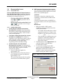
Easy Series Intrusion Control Panel
Release Notes
ICP-EZM2
October 2006
Release Notes for Firmware Version 2.2
1.0
New Features in Firmware
Version 2.2
2.0
Fixed Item from Firmware
Version 1.6 to 2.2
•
Support for wLSN devices. Contact your local
Bosch representative for wLSN device availability.
•
Support for RPS Version 5.4
•
Support for DX2010 Input Expander
Output Activates When Enclosure is Tampered
With: If the EZTS Cover and Wall Tamper Switch is
installed and the control panel enclosure is tampered
with, the appropriate output activates and the control
center announces a tamper message.
•
Support for up to 32 total input points
(hard-wired, wireless, or combination)
3.0
•
Support for 26 languages* (refer to Table 1)
Known Issues in Firmware
Version 2.2
3.1
Control Panel Issues
Table 1: Supported Languages
Language
Arabic
Bulgarian
Croatian
Czech
Danish
Dutch
English (UK)
English (US)
Finnish
Flemish
French
German
Greek
Hungarian
Italian
Norwegian
Polish
Portuguese (European)
Romanian
Russian
Serbian
Slovak
Slovenian
Spanish (European)
Swedish
Turkish
Voice Module Model Number
ICP-EZV2-ARF
ICP-EZV2-BGF
ICP-EZV2-HRF
ICP-EZV2-CSF
ICP-EZV2-DAF
ICP-EZV2-NLF
ICP-EZV2-ENUKF
ICP-EZV2-ENF
ICP-EZV2-FIF
ICP-EZV2-NLBEF
ICP-EZV2-FRF
ICP-EZV2-DEF
ICP-EZV2-ELF
ICP-EZV2-HUF
ICP-EZV2-ITF
ICP-EZV2-NOF
ICP-EZV2-PLF
ICP-EZV2-PTF
ICP-EZV2-ROF
ICP-EZV2-RUF
ICP-EZV2-SRF
ICP-EZV2-SKF
ICP-EZV2-SLF
ICP-EZV2-ESF
ICP-EZV2-SVF
ICP-EZV2-TRF
* Version 2+ of the control panel requires a
Version 2+ voice module. Refer to Table 1 for
voice module model numbers.
•
Fast Format Using Multiple Report
Destinations: If both report destinations in a
route are used (for example, Route 1 Primary and
Route 1 Backup), and you select Fast Format as
the format option for one destination, you must
select Fast Format for the other destination, too.
When using Fast Format, all enabled reporting
destinations must include a phone number.
Failure to do so might result in a communication
failure.
•
Status Announcements during One Button
System Test: To ensure you hear the status of all
tests performed when you press the System Test
button, leave Expert Programming Item 139 (Verbose
System Test Enabled) set to 1.
•
English SMS Text for “Point,” “Output,” and
“Key Fob”: “Point,” “Output,” and “Key Fob”
always appear in English in SMS text messages.
•
Enabling Installer Passcode From Control
Center with Master User Passcode: Entering
the Master User (User 1) Passcode at the control
center does not enable the Installer Passcode,
even if Expert Programming Item 142 is set to 1. You
should enable the Installer Passcode from the
Phone Menu (recommended), or by presenting
the Master User Token to the control center.
ICP-EZM2
•
Route Attempts on Backup Destination: To
ensure the system attempts to send reports using
the backup destination, do not set Expert
Programming Item 305 (Route Attepmts) to a value
less than three.
•
Fire Alarm Not Detected If Preceded By
Unrestored Tamper Condition: If a tamper
condition occurs on a fire point and it remains
unrestored when a fire alarm condition occurs on
the same fire point, the fire alarm condition is not
detected. This issue is only valid for a fire point
with its circuit style option set to 0 (dual 2.2 kΩ
alarm and tamper circuit).
•
3.2
Wall Tamper Condition Disables Control
Center: If a wall tamper condition occurs on a
control center with its wall tamper option enabled,
that control center is disabled and can no longer
access the system. Use a telephone or a keyswitch
to access or control the system.
•
Tampered Hub Prevents Wireless Network
Configuration: When configuring the wireless
network or programming the wireless hub, do not
tamper the hub (Address 50 Tamper). Doing so
prevents the hub from saving wireless
configuration data.
•
No Dialer Delay for Key Fob Panic Alarm: The
control panel immediately sends a panic alarm
and
report to the central station when the
buttons are simultaneously pressed on the wireless
key fob.
•
AC Failure Event History Message: If the
system announces an AC Failure message with a
point or output number, a wireless relay module
or siren lost power on its secondary power
terminals. If the system announces an AC Failure
message without a point or output number, the
control panel has an AC failure condition.
•
Unexpected Alarm Occurs When Pressing the
Button on the Wireless Key Fob: If there is
a faulted Interior point on the system and you
button on the wireless key fob five
press the
consecutive times to arm the system, an
unexpected alarm might occur on the faulted
Interior point.
•
Removing a Wireless Device from the System:
To properly remove a wireless device from the
system, select Option 3 (Delete a Device) from the
Wireless Configuration Menu. Changing the
wireless device’s function setting to 0 (Disabled)
does not delete the device from the system.
Wireless Device Issues
•
Shorted Data Bus Wires Cause Missing
Wireless Devices: If wireless devices are missing
as a result of shorted wires on the data bus, fix the
shorted wires, then remove and reapply all power
to the system to restore the missing wireless
devices.
•
Changing the Batteries in the Key Fob: Only
use 3 V lithium coin cell batteries
(Duracell DL2032 or equivalent).
1. Remove the screws from the back of the key
fob, and remove the end cover (key ring
attached).
2. Remove the old batteries and replace with
new batteries.
Ensure that battery polarity is correct.
3. Replace the end cover and screws.
4. Test the key fob by pressing a button.
If the key fob fails to test the system, ensure
the batteries are properly installed, or reenroll the key fob into the system (User
Maintenance Menu).
3.3
•
RPS Known Issues
RPS Default Discrepancies (UK only): The
defaults for Expert Programming Items 403 (Partial
Close (System On)) and 641 (Output 4 Type) are
correct in the control panel, but not in RPS. The
correct RPS defaults are as follows:
-
Partial Close (System On): Both Routes
-
Output 4 Type: Intrusion and Fire
ICP-EZM2 Release Notes
F01U032264B
Page 2
© 2006 Bosch Security Systems, Inc.
ICP-EZM2
3.4
Documentation Issues
3.4.1
User Guide Issue
•
RPS Connection Descriptions Not Accurate:
The connections methods described in Section 4.6
Remote Programming Software (RPS) are inaccurate.
Below are accurate descriptions.
Incorrect LED Indications for Output Options in
Key Fob LED Status Table: Wireless key fob LED
status indications and output option descriptions are
listed below for Firmware Version 2.1:
-
-
3.4.2
•
Automatic
This option is the primary method to use for
establishing a connection between RPS and the
control panel.
Green on steady and slow amber flash:
or
was pressed to turn an
Either
output on or off.
Connect the internal modem on the RPS PC, or
an external modem, to the control panel. Refer to
Figure 2.
Red on steady and slow amber flash: Either
or
was pressed to turn an output
on for two seconds.
Manual Dial
1.
Installer Guide Issues
Arming Beeps/Graduated Annunication
Description Not Accurate: Expert Programming
Item 148 only controls output arming beeps and
activation during Entry Delay. It does not affect
control center operation.
•
-
-
From the RPS site, the RPS operator uses
a telephone connected in parallel to the
RPS modem and manually dials the
house phone number
2.
The RPS operator selects Manual Dial as the
connection option on the RPS Panel
Communication window.
3.
To answer the incoming call, the RPS
operator clicks the Connect button on the
RPS Panel Communication window to
establish a remote connection between RPS
and the control panel. Refer to Figure 1.
Installer Passcode Override Enabled
Description Not Accurate: The description for
Expert Programming Item 122 is not accurate. Below
are the correct steps to bypass the installer
passcode entry prompt:
1. Short the solder pads together for
approximately 5 sec.
2. Press [#] three times on the house phone, or
press and hold the System Test button for
approximately 15 sec.
The system skips the passcode entry prompt
and announces the Installer Menu options.
The installer dials the RPS phone number
using the house phone, or connects a test
telephone to the control panel’s test posts,
OR
One Button Arming Description Not Accurate
for EN50131-1 Compliance: For EN50131-1
compliance, a user must always present a token or
enter a passcode in order to turn the system on.
For EN countries, do not enable Expert
Programming Item 891 (One Button Arming).
•
Either the installer or RPS operator
establishes a phone connection between the
control panel and RPS:
Figure 1: RPS Panel Communication Window
ICP-EZM2 Release Notes
© 2006 Bosch Security Systems, Inc.
Page 3
F01U032264B
Modem Dial
The RPS operator uses a telephone connected in
parallel to the RPS modem and clicks the
Connect To button in the RPS Panel
Communication Window to dial the premises
phone number.
1.
Connect the internal modem on the RPS PC,
or an external modem, to the control panel.
Refer to Figure 2.
2.
When the control panel answers the incoming
call, the system announces “Enter your
passcode.”
3.
When you hear the control panel modem
tones, press the Connect To button on the
RPS Panel Communication window.
RPS then sends the DTMF tone to connect to
the control panel.
Direct
Figure 2: Internal and External Modem
Connections
3
1
3
2
Select this method to establish a local, on-site
connection between the RPS PC (or laptop) and
the control panel.
1.
On the Telco side of the phone line, ensure
that Tip and Ring are disconnected.
2.
Connect the internal modem on the RPS PC,
or an external modem, to the control panel.
Refer to Figure 2.
If the first communication attempt fails,
connect a 270 Ω to 330 Ω, ¼ resistor in series
with the Tip House side. Refer to Figure 2.
© 2006 Bosch Security Systems, Inc.
www.boschsecuritysystems.com
1- Connection using internal modem
2- Connection using external modem
3- 270 Ω to 330 Ω, ¼ W resistor
(for Direct Connection option only)
F01U032264B
Release Notes
10/06
ICP-EZM2
Page 4 of 4