1
MPXPRO
User manual
User manual
IMPORTANT WARNINGS
ENGLISH
CAREL bases the development of its products on decades of experience in HVAC, on the continuous investments in technological innovations to products, procedures and strict quality processes with in-circuit
and functional testing on 100% of its products, and on the most innovative production technology available on the market. CAREL and its subsidiaries nonetheless cannot guarantee that all the aspects of the
product and the software included with the product respond to the requirements of the final application,
despite the product being developed according to start-of-the-art techniques. The customer (manufacturer, developer or installer of the final equipment) accepts all liability and risk relating to the configuration
of the product in order to reach the expected results in relation to the specific final installation and/or
equipment. CAREL may, based on specific agreements, acts as a consultant for the positive commissioning of the final unit/application, however in no case does it accept liability for the correct operation of
the final equipment/system.
The CAREL product is a state-of-the-art product, whose operation is specified in the technical documentation supplied with the product or can be downloaded, even prior to purchase, from the website www.
carel.com.
Each CAREL product, in relation to its advanced level of technology, requires setup/configuration/programming/commissioning to be able to operate in the best possible way for the specific application. The
failure to complete such operations, which are required/indicated in the user manual, may cause the final
product to malfunction; CAREL accepts no liability in such cases.
Only qualified personnel may install or carry out technical service on the product.
The customer must only use the product in the manner described in the documentation relating to the
product.
In addition to observing any further warnings described in this manual, the following warnings must be
heeded for all CAREL products:
• Prevent the electronic circuits from getting wet. Rain, humidity and all types of liquids or condensate
contain corrosive minerals that may damage the electronic circuits. In any case, the product should be
used or stored in environments that comply with the temperature and humidity limits specified in the
manual;
• Do not install the device in particularly hot environments. Too high temperatures may reduce the life
of electronic devices, damage them and deform or melt the plastic parts. In any case, the product
should be used or stored in environments that comply with the temperature and humidity limits
specified in the manual;
• Do not attempt to open the device in any way other than described in the manual;
• Do not drop, hit or shake the device, as the internal circuits and mechanisms may be irreparably
damaged;
• Do not use corrosive chemicals, solvents or aggressive detergents to clean the device;
• Do not use the product for applications other than those specified in the technical manual.
All of the above suggestions likewise apply to the controllers, serial boards, programming keys or any
other accessory in the CAREL product portfolio.
CAREL adopts a policy of continual development. Consequently, CAREL reserves the right to make changes and improvements to any product described in this document without prior warning.
The technical specifications shown in the manual may be changed without prior warning.
The liability of CAREL in relation to its products is specified in the CAREL general contract conditions,
available on the website www.carel.com and/or by specific agreements with customers; specifically, to the
extent where allowed by applicable legislation, in no case will CAREL, its employees or subsidiaries be
liable for any lost earnings or sales, losses of data and information, costs of replacement goods or services, damage to things or people, downtime or any direct, indirect, incidental, actual, punitive, exemplary,
special or consequential damage of any kind whatsoever, whether contractual, extra-contractual or due to
negligence, or any other liabilities deriving from the installation, use or impossibility to use the product,
even if CAREL or its subsidiaries are warned of the possibility of such damage.
Disposal of the product: the product is made up of metal parts and plastic parts.
In reference to European Union directive 2002/96/EC issued on 27 January 2003 and the
related national legislation, please note that:
1. WEEE cannot be disposed of as municipal waste and such waste must be collected and disposed of
separately;
2. The public or private waste collection systems defined by local legislation must be used. In addition,
the equipment can be returned to the distributor at the end of its working life when buying new
equipment.
3. The equipment may contain hazardous substances: the improper use or incorrect disposal of such
may have negative effects on human health and on the environment;
4. The symbol (crossed-out wheeled bin) shown on the product or on the packaging and on the instruction sheet indicates that the equipment has been introduced onto the market after 13 August 2005 and
that it must be disposed of separately;
5. In the event of illegal disposal of electrical and electronic waste, the penalties are specified by local
waste disposal legislation.
If the appliance is used in a way that is not described by the manufacturer, the specified level of protection may be affected.
“MPXPRO” +030220186 - rel. 1.0 - 22.05.2007
Contents
1. INTRODUCTION
7
1.1 MPXPRO ..................................................................................................................................................7
1.2 Components............................................................................................................................................7
1.3 Functional diagrams .............................................................................................................................8
1.4 Models......................................................................................................................................................10
2. MECHANICAL AND ELECTRICAL INSTALLATION
11
ENGLISH
2.1 Removing the top and side covers.....................................................................................................11
2.2 MX20* board wiring diagram and connections..............................................................................12
2.3 Stepper EEV expansion board wiring diagram (MX2OPSTP*)....................................................14
2.4 PWM expansion board wiring diagram (MX2PPWM*).................................................................14
2.5 0 to 10 Vdc expansion board wiring diagram (MX2OPA100*)....................................................15
3. USER INTERFACE
16
3.1 Display......................................................................................................................................................16
3.2 Keypad and functions...........................................................................................................................16
3.3 Setting and editing the parameters....................................................................................................17
4. Start-up
19
4.1 Recommended initial configuration...................................................................................................19
4.2 Start-up procedure.................................................................................................................................20
4.3 Device start-up procedure...................................................................................................................20
4.4 Navigation................................................................................................................................................20
4.5 Exceptions................................................................................................................................................20
5. BASIC FUNCTIONS
21
5.1 General configuration............................................................................................................................21
5.2 Control......................................................................................................................................................27
5.3 Defrost ....................................................................................................................................................28
5.4 Fans...........................................................................................................................................................30
5.5 Temperature alarms...............................................................................................................................32
6. ADVANCED FUNCTIONS
34
6.1 General configuration............................................................................................................................34
6.2 Control......................................................................................................................................................41
6.3 Electronic expansion valve...................................................................................................................44
6.4 Compressor.............................................................................................................................................51
6.5 Defrost......................................................................................................................................................53
6.6 Fan speed modulation..........................................................................................................................56
6.7 Alarms .....................................................................................................................................................57
6.8 HACCP (Hazard Analysis and Critical Control Point).....................................................................59
7. PROGRAMMING KEY AND COMMISSIONING TOOL 61
7.1 Programming keys IROPZKEY00/A0...................................................................................................61
7.2 Commissioning tool...............................................................................................................................61
8. ALARMS AND SIGNALS 63
8.1 Alarms and signals: display, buzzer and relay.................................................................................63
8.2 Table of alarms and signals: functions enabled/disabled.............................................................64
9. TABLE OF PARAMETERS
65
10. TECHNICAL SPECIFICATIONS
69
“MPXPRO” +030220186 - rel. 1.0 - 22.05.2007
ENGLISH
“MPXPRO” +030220186 - rel. 1.0 - 22.05.2007
1. INTRODUCTION
1.1 MPXPRO
1.2 Components
The series of MPXPRO controllers is made up of:
Fig. 1.a
MPXPRO master (MX20M*****) (Fig. 1.a)
Device that can independently control a refrigeration unit using a wide range of probes, digital or analogue inputs and outputs specially designed and sized for the specific functions. In addition, it is fitted with
a clock (RTC) for the synchronisation of the events in the tLAN and features connection to the supervisor
network (RS85).
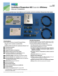
MPXPRO slave (MX20S*****) (Fig. 1.b)
Device similar to the master version, without the serial board (RS85) and Real Time Clock (RTC). These
functions are carried out by the master unit connected in the LAN, or alternatively can be included by
installing the optional clock board and RS85 interface (MX2OP8500).
Fig. 1.b
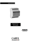
Stepper EEV expansion board (MX2OPSTP**) (Fig. 1.c)
Optional board for controlling a CAREL E2V electronic expansion valve driven by stepper motor. Model
MX2OPSTP0* also has a 0 to 10 V modulating output for the control of external actuators.
It is installed on the main board using special fastening holes.
Fig. 1.c
PWM EEV expansion board (Pulse-Width Modulation (MX2OPPWM**) (Fig. 1.d)
Optional board for controlling an AC or DC PWM electronic expansion valve live. Model MX2OPPWM0*
also has a 0 to 10 V modulating output for the control of external actuators.
It is installed on the main board using special fastening holes.
Fig. 1.d
0 to 10 Vdc expansion board (MX2OPA100*) (Fig. 1.e)
Optional board used to control external actuators with 0 to 10 Vdc modulating output.
It is installed on the main board using special fastening holes.
Fig. 1.e
“MPXPRO” +030220186 - rel. 1.0 - 22.05.2007
7
ENGLISH
MPXPRO is the CAREL product for the complete and advanced management of stand-alone or multiplexed refrigeration units. MPXPRO includes a wide range of integrated microprocessor parametric
controllers, optional electronic boards, terminals, displays and accessories that ensure high flexibility and
extended functions for the management of showcases or cold rooms.
MPXPRO can independently manage the control and operation of a refrigeration unit, implement a vats
series of functions and emergency procedures to avoid critical situations, control stepper or PWM electronic expansion valves, synchronise a master-slave network with a maximum of 5 units, and connect to the
supervisor network for complete monitoring of the installation.
MPXPRO is only available in the “split” version for DIN rail assembly, with the user terminal separate from
the power unit. It can be configured using a remote terminal, remote control, supervisor and commissioning software on a PC directly connected to the user terminal.
RTC board and RS485 interface (MX2OP48500) (Fig. 1.f)
Optional board used to add the RTC and RS85 interface functions in the MPXPRO Slave models. The
master versions are already fitted with this board.
Fig. 1.f
USB/I2C converter (IROPZPRG00) for programming key (Fig. 1.g)
Converter used to interface a PC (running special software) with a standard CAREL programming key
IROPZKEY00/A0 (see Chapter 7).
ENGLISH
Fig. 1.g
USB/tLAN converter for commissioning tool (IROPZTLN00) (Fig. 1.h)
Converter used to interface a PC (running special “commissioning” software) with an MPXPRO device.
Fig. 1.h
Small display terminal (IR**U*****)(Fig. 1.i)
Remote user terminal with 3 digits and buttons for displaying the status and setting the device parameters.
Fig. 1.i
Small display (IR**X*****) (Fig. 1.j)
User display used to display the status of a variable directly set on the instrument.
1.3 Functional diagrams
Fig. 1.j
The MPXPRO controllers are systems that manage refrigeration units (for example, one or a series of multiplexed showcases). These systems are made up of control boards connected together in master-slave
mode; each master board can manage up to slave boards.
The functional diagrams below show some examples of typical applications.
For further information on
electrical connections, see p. 12
“Stand alone” diagram and applicable options
Fig. 1.k
Available options:
• expansion board for the management of CAREL E2V Stepper valves (MX2OPSTP**);
MX2OPSTP**
RS485 3
MX2OPPWM**
master
MPXPRO
High
voltage
MX2OPA100*
MX2OP48500
(only for MX20S*****)
tLAN 3
AUX
AUX
• expansion board for the management of PWM valves (Pulse-Width Modulation) (MX2OPPWM**);
• 0-10 Vdc expansion board (MX2OPA100*)
In addition, the MPXPRO slave (MX20S*****) slave boards (MX20S*****) can be fitted with the RTC and
RS85 serial interface (MX2OP8500)
8
“MPXPRO” +030220186 - rel. 1.0 - 22.05.2007
Master - slave network with terminals and displays
RS485 3
master
MPXPRO
High
voltage
...massimo 4 slave
tLAN 3
AUX
MPXPRO
MPXPRO
High
voltage
High
voltage
3
High
voltage
slave 2
tLAN
MPXPRO
High
voltage
slave 1
tLAN
MPXPRO
3
slave 3
tLAN
slave 4
tLAN
3
3
AUX
AUX
AUX
AUX
AUX
AUX
AUX
AUX
Fig. 1.l
The master unit, connected to the supervisor network, acts as the gateway and coordinates the functions
of the slave units connected in the LAN.
Each device has its own user terminal and display.
Master - slave network with terminals and displays shared by the master
master
RS485 3
MPXPRO
High
voltage
...massimo 4 slave
tLAN 3
AUX
tLAN 2
AUX
MPXPRO
MPXPRO
High
voltage
MPXPRO
High
voltage
slave 1
High
voltage
High
voltage
slave 2
slave 3
Fig. 1.m
The master unit, connected to the supervisor network, acts as the gateway and coordinates the functions
of the slave units connected in the LAN.
The user terminal connected to the master unit can be used to navigate inside the local network and
modify and/or display the settings and variables of all the slave units connected.
RS485 supervisor network
RS485 3
MPXPRO
High
voltage
MPXPRO
MPXPRO
High
voltage
master 1
High
voltage
master 2
...master n
Fig. 1.n
Connection of the master unit to the RS85 serial supervisor network. Each master unit can act as a
gateway to the supervisor for any slave units connected.
“MPXPRO” +030220186 - rel. 1.0 - 22.05.2007
9
MPXPRO
slave 4
ENGLISH
AUX
tLAN 2
1.4 Models
The controllers, options and accessories of the MPXPRO series are available in the following versions:
Basic models
Code
Master/ RS485
Relay
Pt1000 E2V Driver PWM 0-10 Vdc PWM
Slave
& RTC
Driver output outputs
MX20M00EO0
Master
Y
5R (8-2HP-16-8-8)
MX20S00EO0
Slave
N
5R (8-2HP-16-8-8)
MX20S10EO0
Slave
N
3R (8-0-16-0-8)
(Y:���������������������������������������
present, N: optional, -: Not available�)
Tab. 1.a
Full optional models
Master/ RS485
Relay
Pt1000 E2V Driver PWM 0-10 Vdc PWM
Slave
& RTC
Driver output outputs
MX20M21EO0 Master
Y
5R (8-2HP-16-8-8)
Y
2
MX20S21EO0
Slave
N
5R (8-2HP-16-8-8)
Y
2
MX20S31EO0
Slave
N
3R (8-0-16-0-8)
Y
2
(Y:present, N: optional, -: Not available)
Tab. 1.b
ENGLISH
Code
Boards with E2V driver option pre-installed
Code
MX20M25EO0
MX20S25EO0
MX20M24EO0
MX20S24EO0
Master/ RS485 Relay
Slave & RTC
Master
Slave
Master
Slave
Y
N
Y
N
5R (8-2HP-16-8-8)
5R (8-2HP-16-8-8)
5R (8-2HP-16-8-8)
5R (8-2HP-16-8-8)
Pt1000 E2V Driver PWM 0-10 Vdc PWM
Driver output outputs
Y
Y
Y
Y
Y
Y
-
Y
Y
Y
Y
Y
Y
2
2
2
2
(Y:present, N: optional, -: Not available)
Tab. 1.c
Options and accessories
Code
IR00UGC200
IR00XGC200
IR00UG6200
IR00XG6200
MX2OP48500
TRADRBE240
TRA00BE240
IROPZTLN00
IROPZPRG00
Description
Terminal (green LED, full optional, IR, commissioning)
Display (green LED, full optional, IR, commissioning)
Terminal (green LED, no options, without IR, without commissioning)
Display (green LED, no options, without IR, without commissioning)
MPXPRO OPTION, RS485 + RTC MODULE
Transformer for DIN 230Vac/24Vac 20VA with fuse carrier
Transformer for PANEL 230Vac/24Vac 20VA with fuse carrier
Commissioning interface (USB-tLAN)
Programming key interface (USB-I2C)
Tab. 1.d
10
“MPXPRO” +030220186 - rel. 1.0 - 22.05.2007
2. MECHANICAL AND ELECTRICAL INSTALLATION
The following paragraphs illustrate the assembly procedures and the electrical connections for the MPXPRO board and the MX2OPSTP*, MX2OPPWM*, MX2OPA100* expansion boards*
2.1 Removing the top and side covers
Important: The assembly operations must be
performed with the board discon
nected from the power supply
Fig. 2.a: removing the top cover
press sideways
remove the cover
Fig. 2.a
Fig. 2.b: removing the side cover
press the cover sideways at the hinges
remove the cover
Fig. 2.b
“MPXPRO” +030220186 - rel. 1.0 - 22.05.2007
11
ENGLISH
2.2 MX20* board wiring diagram and connections
The diagram refers to a full optional board (maximum inputs and outputs).
To check which inputs and outputs are effectively present on the model in question, see par. 1. Models
Important: The connections must be performed with the board disconnected from the power supply.
N
L
1
2
L
N
3
4
NO NC
AUX3
AUX1
AUX2
( (
( (
( (
5
C
6
R1
ENGLISH
MX20**E**
UL 873
8
9 10 11 12 13
NO NC
R2
C
NO
R3
14 15 16
C
NO NC
R4
R5
R2
R3
R4
8 (2) A N.O.
8 (2) A N.C.
6 (4) A N.O.
8 A 8 FLA
72 LRA
8 A 5 FLA
30 LRA
6 A 2 FLA
12 LRA
6 (4) A N.O.
6 (4) A N.C.
6 A 2 FLA
12 LRA
S4/
S3 GND DI1
37 36 35 34 33
PWM1 LOAD 1
PWM2 LOAD 2
MX2OP48500
(only for MX20S*****)
CLOCK
and
SERIAL INT.
MX20P485**
-10T50
S2
12 V
Mounted on
MX20S*****
R5
8 (10) A N.O.
Maximum currents with removable vertical connectors cod. MX20***(C,I,O)**.
For more details, please refer to the technical leaflets.
S1
PWM modulating fans
(*Req. additional
module as MCHRTF*)
Expansion board:
- E 2V driver MX2OPSTP**
- PWM driver MX2OPPWM**
- 0...10 Vdc Analog output MX2OPA10**
6 (4) A N.O.
6 (4) A N.C.
6 A 2 FLA
12 LRA
20 mA max
12 Vdc
Trim heater
C
: 230 V~ 50 mA~ max
R1
EN60730-1
7
NO C
19 18 17
N
PWM2 PWM1 12 V
Power Supply
L
230 V~
50 mA~ max
IROPZKEY00/A0
PROG. KEY
S5/ S6/
S7/
DI2 DI3 GND DI4 5Vdc
T.U.I. M.S.N. GND Tx/Rx+ Tx/RxDI5 GND VL Tx/Rx
Tx/Rx
32 31 30 29 28
27 26 25 24 23
22
21
To be used only with
control switch off
(no Power Supply)
20
Default connection:
Only “Master units”
to be connected
on RS485
Supervisor
RS485
Shield
NTC
NTC
NTC
NTC
RATIOMETRIC
AIR OFF TEMPERATURE
PROBE (Sm)
DEFROST TEMPERATURE
PROBE (Sm)
AIR ON TEMPERATURE
PROBE (Sr)
SUCTION TEMPERATURE
PROBE (TsuctEEV)
EVAPORATION PRESSURE
PROBE (T/PsatEEV)
Master/Slave network (max. 10 meters between controllers)
tLAN
Slave 1
Slave 2
Slave 3
Slave 4
Shield
Terminal/user interface (max. 10 meters complete line)
IR*U*
tLAN
IR*X*
AUX
AUX
Possible connection:
S2
S4/
S3 GND DI1
37 36 35 34 33
S5/ S6/
S7/
DI2 DI3 GND DI4 5Vdc
Power
Supply
Rx/Tx
Gnd
S1
32 31 30 29 28
Power Supply
GND
Rx/Tx
GND
1 2 3
Connection: VL (25) GND (26)
NTC /PTC/Pt1000
T.U.I.
Tx/Rx (24)
Ratiometric
pressure
probe 0...5 Vdc
0...10 Vdc
4...20 mA
Analogic input
0...10 Vdc
(external power
supply)
Analogic input
4...20 mA
(external power
supply)
Terminal
Important:
S7/
GND DI4
30 29
S7/
GND DI4
30 29
- The board must not be installed on surfaces that exceed 70 °C at 50 °C ambient and 80 °C with 60 °C ambient;
- Use an external disconnect switch positioned near the appliance that is compliant with the IEC6097-1 and
IEC6097-3 standards;
- Use cables rated to 90°C, if the temperature of the terminals exceeds 85 °C, use cables rated to 105 °C;
- The connection cables must guarantee insulation up to 90°C and if necessary up to 105 °C, when the temperature
of the relay terminals exceeds 85 °C;
- If the appliance is used in a way that is not described by the manufacturer, the specified level of protection may be
affected;
- If the current is higher than 6 amperes on relay R1, R2, R3, R, R5, only use cables with a cross-section of 2.5 mm2
(1 AVG);
- The board must not be accessible to unauthorised persons.
12
28
29
30
31
5Vdc
S7/D1
GND
S6/D13
(see the technical
leaflets +050000135)
Use only one
pressure probe
Pressure probe connection:
Connect with CAREL cable
SPKC003310 or SPKC005310
connection with
0T50
S6/
S7/
DI3 GND DI4 5Vdc
31 30 29 28
Colour
Green
Black
White
Green
White
White
White
Black
CAREL electronic press. probe
CAREL code
Range
(barg)
min max
Ref. probe.
SPKT0053R0 -1.0 .2 2CP5-52
SPKT0013R0 -1.0 9.3 2CP5-6
SPKT003R0 0.0 17.3 52CP36-01
2CP5-66
SPKT0033R0 0.0 3.5 2CP5-7
SPKT00B6R0 0.0 5.0 2CP50-1
OR
probe ref.
probe ref.
Fig. 2.c
“MPXPRO” +030220186 - rel. 1.0 - 22.05.2007
Power supply and digital outputs
Terminal
Function
1
2
3
4
5
6
7
8
9
10
11
12
13
14
15
16
L
N
NO
NC
C
NO
C
NO
NC
C
NO
C
NO
NC
C
Power supply
Type of relay
230 Vac 50 mA max. Mx20*A*: 115 Vac 100 mA max
Relay 1
EN60730-1: 6(4)A
UL 873: 8 A 2 FLA 12 LRA
Relay 2
EN60730-1: 8(10) A
UL 873: 12A 12 FLA 72 LRA
EN60730-1: 8(2) A
UL 873: 12 A 5 FLA 30 LRA
Relay 3
Not used
Relay 4
Relay 5
EN60730-1: 6(4) A
UL 873: 8 A 2 FLA 12 LRA
EN60730-1: 6(4) A
UL 873: 8 A 2 FLA 12 LRA
ENGLISH
Tab. 2.a
Open collector/PWM analogue output connections
Terminal
Function
17
18
19
+12 V
PWM1
PWM2
Power supply
Open collector PWM1 20 mA max 12 Vdc
Open collector PWM2 20 mA max 12 Vdc
Tab. 2.b
LAN connections
Terminal
20
21
22
23
26
24
25
26
TX/RXTX/RX+
GND
M.S.N.
TX/RX
GND
T.U.I
TX/RX
VL
GND
Function
Supervisor network connection (shielded cable).
Depending on the model, the main board may have two
open collector PWM analogue outputs for connecting:
− SSR relay for the anti-sweat heaters on the display cabinets (hot wire);
− Phase cutting controllers for inductive loads (e.g. fans with inductive motors for opto-isolated control);
− Phase cutting controllers for capacitive loads (e.g. fans with BRUSHLESS motors for opto-isolated control).
Type of network
RS485
Connection to master-slave LANM.S.N. Master/Sla- tLAN network
ve network (shielded cable).
Connections on the MPXPRO display and terminals.T.U.I. (terminal/user interface)
tLAN terminals and display
Tab. 2.c
Digital (DI1 to DI5) and analogue inputs (S1 to S7)
Terminal
Type of inputs
26
27
28
29
30
GND
DI5
5Vdc
S7/DI4
GND
28
30
31
30
32
33
34
35
5Vdc
GND
S6/DI3
GND
S5/DI2
S4/DI1
GND
S3
36
37
Multifunction digital input.
Probe group
-
Multifunction digital input;
4
NTC probe, PTC, PT1000;
0 to 5 Vdc ratiometric probe (power term. 28, 5 Vdc);
0 to 10 Vdc analogue input (external p.s.)*;
4 to 20 mA analogue input (external p.s.)*.
Multifunction digital input;
3
NTC probe, PTC, PT1000;
0 to 5 Vdc ratiometric probe (power term. 28, 5 Vdc).
Multifunction digital input;
2**
NTC probe, PTC, PT1000.
NTC probe, PTC, PT1000.
Important:
All the contacts should be galvanically insulated by adding
further relays for each contact
The digital inputs must not be connected in parallel, otherwise the board may be damaged.
1
S2
S1
Tab. 2.d
*N.B.: The devices with 4 to 20 mA or 0 to 10 output Vdc connected to input S7 cannot be powered directly
from the MPXPRO. They therefore require an appropriate external power supply.
**Important: The type of input connected to each probe in the same group can be configured by just one
parameter. Consequently, for group 1, for example, there is just one parameter that defines the type of input,
and that must therefore be the same for all the probes in the same group.
For group 2, despite there being just one parameter, mixed combinations are possible, excepting different types
of temperature probes on the two inputs.
“MPXPRO” +030220186 - rel. 1.0 - 22.05.2007
13
2.3 Stepper EEV expansion board wiring diagram (MX2OPSTP*)
The input 0 to 10 Vdc must feature
reinforced insulation with reference
to its internal power supply
GND
0...10 Vdc
73 74 Analogic
output only for
MX2OPSTP0*
Tight screw and nut after
installing connector/cable and E2V.
MX2OPSTP*
CAREL E2VCABS*
do not connect to
any “GND” Terminal
Important:
before installing the expansion board, disconnect the power
supply and remove the plastic cover.
connection cable
1 3 2 4 5
75
84 83 82 81 80 79 78 77 76
ENGLISH
Green
Brown/Red
Yellow/Black
White
Shield
84
83
82
81
80
G0 G
Earth
Fuse
0.8 A
24 Vac
20 VA
Suggested transformer
for one module:
• TRADRBE240 with
DIN rail
• TRA00BE240 for panel
installation
Unique correct
connection view
(no other possible
connections).
E2VCON* not suitable
for refrigeration
application.
230 Vac
G0 OUT GND
G
B- B+
Fuse 4 A
Battery
12 V-1.2 Ah
Optional kit battery: EVBAT00300
For further information, please refere to the “EEV system guide”
(code +030220810) available in the web site www.carel.com, in
the literature section.
Fig. 2.d
MX2OPSTP* board connections
Terminal Connection
8
83
82
81
80
79
78
77
76
75
7
73
green
brown/red
yellow/black
white
shield
12 Vbat
GND
GO
G
EARTH
0 to 10 Vdc
GND
CAREL
E2VCABS610
cable
Function
Connection to CAREL EEV expansion valve
Optional battery
Power supply
0 to 10 Vdc output
Tab. 2.e
Important:
before installing the expansion board, disconnect the power
supply and remove the plastic cover.
2.4 PWM expansion board wiring diagram (MX2PPWM*)
PWM valve
115-230 Vac
20 W max 5 W min
POWER SUPPLY N
115-230 Vac L
25 W max
DC/AC output
PWM
ac
PWM
dc
+
N L
PWM valve
115 Vdc RMS-230 Vdc RMS
20 W max 5 W min
Use
PWMac or PWMdc
valves alternatively
–
60 61 62 63 64 65
MX2OPPWM*
Analogic
output only for
MX2OPPWM0*
68 67 66
0...10 Vdc
GND
The input 0 to 10 Vdc must feature
reinforced insulation with reference
to its internal power supply
Fig. 2.e
1
“MPXPRO” +030220186 - rel. 1.0 - 22.05.2007
MX2PPWM* board connections
Terminal Connection
68
67
66
65
64
63
62
61
60
Function
0 to 10 Vdc output
GND
0 to 10 Vdc
Not used
+
L
N
N
L
DC PWM valve
AC PWM valve
Power supply
Tab.2.f
ENGLISH
2.5 0 to 10 Vdc expansion board wiring diagram (MX2OPA100*)
Fig. 2.f
MX2OPA100*
Analogic
output
Important:
before installing the expansion board, disconnect the power
supply and remove the plastic cover.
42 41 40
0...10 Vdc
GND
MX2OPA100* board connections
Terminal Connection
42
41
40
GND
0 to 10 Vdc
Not used
The input 0 to 10 Vdc must feature
reinforced insulation with reference
to its internal power supply
Function
0 to 10 Vdc output
Tab.2.g
“MPXPRO” +030220186 - rel. 1.0 - 22.05.2007
15
3. USER INTERFACE
This chapter describes the features and the functions available to display the status and set the parameters of the MPXPRO series controllers.
The basic MPXPRO series interfaces are:
• IR**U*****: display with three digits and function icons.
• IR**X*****: user terminal that, as well as the display, also features a keypad with four buttons for
navigating the device function menus.
• Supervision software
• Commissioning tool.
IR**U****
3.1 Display
The IR**U***** display (Fig. 3.a) shows the readings of the probes connected to the controller (see
parameter /t1 p. 22 and /t2, p. 38), and the general status of the device, using the corresponding icons.
The numeric display can show values in the range -50T150 °C, with decimal resolution in the range
-19.9T19.9 °C (see parameter /6, p. 38)
ENGLISH
AUX
Fig. 3.a
Icons and functions
Icon
Function
Description
Icon meaning / function status
Off
Flashing
Not active
Activation delayed by protection times
On
Compressor
Compressor output status
Active
Fan
Fan output status
Active
Not active
Activation disabled externally or by procedure in progress
Defrost
Defrost output status
Active
Not active
Activation disabled externally or by procedure in progress
Aux
Alarm
Auxiliary output status
Alarm status during normal operation or from digital input
RTC option
Not active
No active alarm
Active alarms
Light
Active
Pre-activation of a delayed
external digital alarm
Control in night-time operation,
at start-up comes on to indicate
the option is present
Local or network light output status Active
Service
General service signals
HACCP
Cont. cycle
HACCP alarm signal
Continuous cycle function status
Clock
Control in daytime operation Clock alarm
Not active
On the master indicates the upda- No malfunction
te of the parameters to the slave
Function enabled
Function not enabled
On
Off
Malfunction (System error). Contact service.
HACCP alarm active, signal on the display HA / HF
Request in progress
Tab. 3.a
IR**X****
3.2 Keypad and functions
The IR**X***** user terminal (Fig. 3.b) is an interface that as well as the display functions, provides
access to the MPXPRO parameter configuration menu using the keypad located next to the display.
aux
Depending
on the type of connection and the configuration of the local network, the entire network can
be controlled from just one point. The table below describes the main functions that are immediately
aux by pressing the specific combination of keys. Further information on the procedures for
obtainable
def
managing the network and setting the parameters is shown in the following paragraphs.
AUX
Fig. 3.b
Category
Set point
def aux
Keypad
aux controls
Buttons
Duration
Function
Temperature set point.
Set
aux
or
aux
Set
Access to the parameters Type F parameters (frequent)
def
def
Type C parameters (configuration)
or
Defrost
Local defrost
aux
def
Set
Auxiliary
AUX
Network functions,
master only
&
&
def
aux
Display network unit status from master
Reset default parameters
Alarm log
5s
aux
&
def aux
Set
Set
Set
Alarms
def
def
def
Confirm the password, the first type C parameter is displayed
The changes are saved
dFb: start defrost call
dFE: end defrost call
dFb: start defrost call
dFE: end defrost call.
ccb: start continuous cycle call
ccE: end continuous cycle call
aux
def Set
aux
Copy parameters from master to slave
Default
5s
aux def
Set Set
AUX output
Set
aux
aux
Set
aux
aux
def
&
aux
Set
def
def
5s
aux
& Set &
def
aux
Set
def def
atSet
start-up
& Set
aux
Set
def
Manual alarm reset
def
Mute buzzer and disable alarm relay **
&
Set Set
aux
def
&
HACCP menu
aux
Set
16
aux
aux
For further info see par. 3.3. “Copy parameters from master to slave”
Select slave unit, see par. 3.3.2 “Display network unit status from master”
Set
5s
Enter password (default )
see par. 3.3.5 Alarm log
‘rES’: indicates the alarms have been reset*
Set
def
Set
def
Enter password (default 66)
def
Set
aux aux
HACCP
def
Set
Set
aux
5s
def aux
def
Multiplexed defrost
From master only
Continuous cycle
Enter password (default 22)
aux
Set
def
Save set point and return to initial display
The first type F parameter is displayed
5s
def
aux
aux
Type C parameters (configuration)
5s
aux
Set
& Set
aux
Exit parameters
def
def
Display /Notes
Set point value flashing
Change the set point
&
def
def
see par. 3.3.6 HACCP alarms
Tab. 3.b
Set aux
Set
Note:
def*Resets the alarm delays ** Disables the slave offline signals for one minute.
aux
“MPXPRO” +030220186 - rel. 1.0 - 22.05.2007
Set
def
Set
def
3.3 Setting and editing the parameters
The following paragraphs explain Table 3.a: “Functions and associated buttons” and the other modes for
setting the MPXPRO.
3.3.1 Selecting the network unit (from master unit only)
If using a user terminal connected directly to the master unit, the “select network unit” function can be
used to choose the desired unit. After having identified the required setting (e.g. edit parameters, access
the alarm log,...), then:
• Scroll the list of slave units available pressing UP or DOWN.
• Press SET to select the desired unit.
• To return to the normal display press PRG.
The control will in any case return to the normal display after a timeout of around 1 minute.
NB: uM indicates the master unit, u1 indicates slave unit 1, u3o indicates unit 3 is offline.
This specific procedure can be managed from the master unit only, if the user terminal is connected to a
slave unit the procedure is limited to that slave only.
ENGLISH
3.3.2 Displaying the network unit status from the master (Virtual Console)
If using a user terminal connected directly to the master unit, the status of any slave unit can be displayed (as
if the terminal were connected to the selected unit). Procedure:
1. Access the “Display network unit status from master” function (see Table 3.b “Buttons and Functions”).
2. Scroll the list of units available by pressing UP or DOWN
3. Use SET to select the unit and display the status.
. The display shows the status of the selected unit, that is, the value shown on the display and the icons
refer to the selected unit in the sub-network.
5. To return to the normal display press PRG. The control in any case returns to the normal display after a
timeout of 1 min.
The terminal connected to the master unit only allows a
general overview of the entire local network.
3.3.3 Modifying the parameters
1. Access the desired configuration menu “Type C parameters” or “Type F parameters” (see Table 3.b
“Functions and associated buttons”)
2. If using a user terminal connected directly to the master unit, select the unit (see par. “3.3.1 Selecting
the network unit”).
3. Press UP or DOWN until reaching the desired parameter (the icon for the function will be displayed,
together with the parameter). Alternatively: Press PRG to display the menu of parameter categories.
Press UP or DOWN until reaching the desired category of parameters and press SET. The list of
parameters in the selected category is displayed, then press UP or DOWN until reaching the desired
parameter (the display shows the icon that represents the category the parameter belongs to, see
Table 3.c).
. Once having reached the desired parameter, press SET
5. Increase or decrease the value of the parameter using UP or DOWN
6. Press SET to temporarily save the new value and return to the display of the list of parameters to
modify other values.
7. If the parameter has sub-parameters, after having selected the parameter as in point 4, press SET again
to enter the sub-menu, use the UP or DOWN button to scroll between the sub-parameters, which can
be modified like a normal parameter. Press SET again to temporarily save the values and return to the
higher level menu.
8. Once all the modifications have been made, to permanently save the new values assigned to the
parameters, press PRG for 5 seconds. To ignore the modifications, wait 60 seconds without pressing
any button (TIMEOUT).
Parameter category
Probe
/
Control
r
‘CtL’
Compressor
c
‘CMP’
Defrost
d
‘dEF’
Alarms
A
‘ALM’
Fans
F
‘FAn’
Expansion valve
E
‘Eud’
3.3.4 Copy parameters from master to slave (Upload)
Configuration
Log
H
HS
‘CnF’
‘HSt’
HACCP
H
‘HcP’
Parameter categories
All the parameters can be uploaded from a master unit to the slave units in the sub-network. This procedure can be used instead of the programming key, with the advantage of being able to update all the
slave boards in the sub-network at the same time (rather than having to do it individually for each board
with the programming key). Procedure:
1. Access the “Copy parameters from master to slave” menu (see Table “3.b Functions and associated
buttons”)
2. Scroll the list of units available using UP or DOWN
3. Press SET to select the desired unit. Selecting ALL means all the slave units in the sub-network will be
programmed.
. During the programming process, the display on the terminal shows the normal display alternating
with the message uPL, and the
icon comes on.
icon goes off.
5. Once the programming procedure is complete, the message uPL disappears and the
In the event of errors, the message uPX is displayed (X= number of the slave unit where the error
occurred).
Display
‘Pro’
Icon
Tab 3.c
3.3.5 Alarm log
Below are the instructions for managing the alarms saved by MPXPRO:
1. Access the “Alarm log” menu (see Table “3.b Functions and associated buttons”)
2. If using a master unit, select the desired unit (par. “3.3.1 Selecting the network unit”).
3. Scroll the list of alarms by pressing UP and DOWN
. Select the desired alarm by pressing SET, showing: the alarm code, hours, minutes and duration of the
alarm, using the UP and DOWN buttons
5. To return to the list, press SET again
6. To exit the alarms menu, press PRG for 5 seconds, or alternatively wait 60 seconds without pressing
any button.
To delete the alarm log, press SET & UP & DOWN for 5 seconds (the display will show the alarms deleted
“MPXPRO” +030220186 - rel. 1.0 - 22.05.2007
Prefix
17
message, rES).
3.3.6 HACCP alarms
The most recent 6 HACCP alarms (HA/HF) can be displayed and managed inside the HACCP menu.
1. Access the “HACCP menu” (see Table “3.b Functions and associated buttons”)
2. If using a master unit, select the desired unit (par. “3.3.1 Selecting the network unit”).
3. Scroll the list of alarms by pressing UP and DOWN
. Press SET to select the desired alarm.
5. Using the UP or DOWN button, view the description of the selected alarm, that is: year, month, day,
hours, minutes and duration in minutes.
6. Press SET again to return to the previous list.
ENGLISH
In addition, the HACCP alarm menu allows the following operations:
• Delete an individual HACCP alarm by pressing SET & DOWN for 5 seconds when displaying the list
of alarms. This causes the HACCP to flash, the display shows the message rES and the monitoring of
HACCP alarms is reinitialised.
• Delete the entire memory of HACCP alarms, by pressing SET & UP & DOWN for 5 seconds. This procedure displays the message rES, deletes the entire memory of alarms and reinitialises the monitoring of the HACCP alarms.
18
“MPXPRO” +030220186 - rel. 1.0 - 22.05.2007
NTC /PTC/Pt1000
4. START-UP
This chapter describes the configuration of the inputs and the outputs suggested by CAREL, as well as the
controller start-up procedure to ensure the correct commissioning of the installation.
Ratiometric
pressure
probe 0...5 Vdc
4.1 Recommended initial configuration
37 36 35 34 33
S5/ S6/
S7/
DI2 DI3 GND DI4 5Vdc
DI5 GND
32 31 30 29 28
27 26
S7/
GND DI4
30 29
S7/
GND DI4
30 29
Default
Defaultconfigurations:
connection:
S1
S2
S4/
S3 GND DI1
32 31 30 29 28
2
L
N
NTC
RATIOMETRIC
AIR ON TEMPERATURE
PROBE (Sr)
SUCTION TEMPERATURE
PROBE (TsuctEEV)
EVAPORATION PRESSURE
PROBE (T/PsatEEV)
Important:
The availability of the output depends on the code of the
controller, consequently check the hardware before making
the connections.
B@ A5 A12: Digital input configuration, p. 22
A@ /Fd, /FE: Assigning the functions of the probes, p. 37
A@ /P3, /U6, /L6: Analogue input configuration p. 35
EVAPORATION PRESSURE
PROBE (T/PsatEEV)
SUCTION TEMPERATURE
PROBE (TsuctEEV)
AIR ON TEMPERATURE
PROBE (Sr)
DEFROST TEMPERATURE
PROBE (Sm)
AIR OFF TEMPERATURE
PROBE (Sm)
S4/ S5/ S6/ GND S7/ 5Vdc
The default configuration
S1 envisages:
S2 S3 GND DI1
DI2 DI3
DI4
• Group 1: pre-configured as NTC cabinet temperature probes
37 36 35 34 33 32 31 30 29 28
S1: NTC outlet probe Sm
S2: NTC defrost probe Sd
S3: NTC inlet probe Sr
• Group 2: pre-configured as NTC probes, auxiliary temperatures – digital inputs
S4: NTC superheated gas temperature probe (only configured on the models with valve driver
included, see advanced parameter /Fd)
S5: digital input DI2 can be configured (function not configured, see basic parameter A5)
• Group 3: pre-configured as pressure probe
S6: ratiometric evaporation pressure probe (only configured on the models with valve driver NTC
NTC
RATIOMETRIC
included,NTCsee NTC
advanced
parameters
/P3, /U6,
/L6, /FE)
• Group 4: pre-configured as NTC probe
S7: function not configured (see Assigning the advanced functions of the probes, p. 42)
• Group 5: pre-configured as DI5 digital input (function not configured, see basic parameter A12)
For further information, see the following sections:
• Basic functions: Temperature probe configuration, p. 21
• Basic functions : Digital input configuration, p. 22
• Advanced functions: Analogue inputs, p. 35
• Advanced: Assigning the advanced functions of the probes, p. 37
1
NTC
Fig. 4.b
Default connection: Fig. 4.a
Power supply
230 V~
50 mA~ max
L N
NTC
DEFROST TEMPERATURE
PROBE (Sm)
4...20 mA
Analogic input
4...20 mA
(external power
supply)
S7/
GND DI4
30 29
NTC
AIR OFF TEMPERATURE
PROBE (Sm)
S7/
GND DI4
30 29
0...10 Vdc
Analogic input
0...10 Vdc
(external power
supply)
Ratiometric
pressure
probe 0...5 Vdc
NTC /PTC/Pt1000
37 36 35 34 33
S5/ S6/
S7/
DI2 DI3 GND DI4 5Vdc
N
L
3
4
NO NC
R1
5
C
AUX3
AUX1
AUX2
( (
( (
( (
6
7
8
9 10 11 12 13
NO C
NO NC
R2
R3
C
NO
R4
C
14 15 16
NO NC
C
R5
see Restoring the default parameter settings
Fig. 4.c
“MPXPRO” +030220186 - rel. 1.0 - 22.05.2007
19
ENGLISH
S4/
S3 GND DI1
S2
4...20 mA
S1
Analogic input
4...20 mA
(external power
supply)
• Initial configuration of the inputs
0...10 Vdc
Analogic input
0...10 Vdc
(external power
supply)
MPXPRO features highly configurable inputs and outputs. CAREL in any case recommends the basic
configurationd on the default settings of the parameters. By following this suggestion, the controller can
independently manage the main functions in most applications, without having to significantly modify the
settings of the parameters. The suggested settings are shown on all the wiring diagrams.
• Initial configuration of the outputs
The default configuration envisages:
Relay 1: solenoid valve / compressor (not modifiable)
Relay 2: light (see basic parameter H7)
Relay 3: heaters defrost (not modifiable)
Relay 4: fans (see basic parameter H1)
Relay 5: alarm (see basic parameter H5)
PWM 1: anti-sweat heaters – hot wire (if present, see basic parameter Hhu p. 26)
PWM 2: not used
B@ H1, H5, H7: AUX output configuration, p. 24
B@ Hhu: Hardware configuration, p. 26
ENGLISH
• Sets of pre-configured parameters
To further assists the configuration phase, MPXPRO features two sets of pre-configured parameters that
represent the typical configurations of two specific applications:
• Cabinet 1: NT utility - normal temperature
• Cabinet 2: LT utility - low temperature
These pre-configurations are can be selected using the procedure for loading the default parameters, and
then selecting the desired set of parameters.
4.2 Start-up procedure
MPXPRO features a special procedure when first starting that ensures the controller operates in safe
conditions. This procedure is designed above all to help the installer when starting an installation in which
the devices have not been previously programmed and/or when replacing the controllers in existing
systems. In these cases, this procedure avoids problems of conflicts on the supervisor or in the master/
slave network and the return of liquid refrigerant to the compressors (very frequent situations when the
instruments have not been programmed correctly).
When first powered up, MPXPRO runs a procedure that freezes all the functions of the controller and
only allows the user terminal to be used to set the parameters that are considered critical for:
• correct communication of the controller with the supervisor;
• management of the electronic valve.
The scope of this procedure does not cover the complete programming of the instrument, but rather
the first start-up in safe conditions so as to avoid critical situations and be able to set all the remaining
parameters at a later stage on the user terminal or via the supervisor.
During this procedure, the device remains in standby and all the functions are deactivated, the controller
consequently does not implement any control functions or communicate with the supervisor. These
restrictions end only after having set all the required parameters.
NB: Based on the specific application, these parameters may
not be useful, for example, if the electronic expansion valve is
not used. In these cases, simply confirm the default values set
on the controller.
4.3 Device start-up parameters
When first starting the controller, the user terminal does not display the traditional menu, but rather
automatically enters a temporary configuration menu that only displays the parameters defined as critical
for the initial operation of the installation. By default, the following parameters are displayed:
Code
H0
In
Sn
/P2
/P3
/Fd
/FE
/U6
/L6
P1
PH
Application
Supervisor and LAN
Electronic expansion valve
Description
Serial / LAN address
Unit configuration, Master or Slave
Number of Slaves connected to the Master
Select type of probe, Group 2 (S4-S5 / DI1-DI2)
Select type of probe, Group 3 (S6 / DI3)
Assign evaporator outlet temp. probe
Assign saturated evaporation temp. probe
Max. value of sensor S6
Min. value of sensor S6
Type of valve
Type of refrigerant
Tab.4.a
4.4 Navigation
This menu can be navigated in the traditional manner, through the sub-sets of parameters. To exit
the menu press and hold the PRG button, after having set all the parameters displayed. In fact, each
individual parameter must be selected using the SET button, the value set correctly using UP or DOWN
and saved by pressing the SET button again. The configuration procedure is simplified by the icons
being shown on the display corresponding to each parameter that has not yet been set. Only when all the
parameters have been set, and consequently the icons corresponding to all the start-up parameters are
off, will it be possible to exit this procedure.
4.5 Exceptions
As already mentioned, this procedure is especially useful when starting and programming the installation
directly. Nonetheless, the list of parameters displayed can be changed and/or the procedure disabled by
programming the parameters via programming key or commissioning tool. For further information, see to
the documents on the commissioning tool..
20
“MPXPRO” +030220186 - rel. 1.0 - 22.05.2007
5. BASIC FUNCTIONS
MPXPRO features a vast range of applications and functions for the control and management of refrigeration units. To simplify the use of the functions available, two levels have been identified:
• (B@) Basic: simple, standard functions
• (A@) Advanced: complex applications and functions, reserved for expert users (see Chap. 6 Advanced
functions, p. 34)
The basic functions, described in this chapter, include the typical parameters for entry-level use of the
controller. These involve::
5.1 5.1 General configuration (I/O, hardware and LAN)
5.2 Control (set point)
5.3 Defrost
5.4 Fans
5.5 Temperature alarms
Note:
To simplify understanding, the basic and advanced parameters are highlighted by references shown on the side of the
page. For example, if the text refers to parameter /FA, the
following reference will be shown on the side of the page:
“B@ /FA p. 21”
ENGLISH
5.1 General configuration
The following paragraph describes the basic configurations relating to:
5.1.2 Temperature probes
5.1.3 Digital inputs
5.1.4 Auxiliary outputs
5.1.5 LAN
5.1.6 Hardware
5.1.1
List of parameters
Code
Parameter
Temperature probes
/FA
Assign outlet temperature probe (Sm)
/Fb
Assign defrost temperature probe (Sd)
/Fc
Assign intake temperature probe (Sr)
/t1
Select display on the terminal
Digital inputs
A4
Configure function of digital input DI1 on S4
A5
Configure function of digital input DI2 on S5
A10
Configure function of digital input DI3 on S6
A11
Configure function of digital input DI4 on S7
A12
Configure function of digital input DI5
A7
Delay time for delayed external alarm
Auxiliary outputs
H1
Configure function of AUX1 output
H5
Configure function of AUX2 output
H7
Configure function of AUX3 output
H9
Select function associated with the AUX button (Light or AUX)
LAN
In
Select type of unit, MASTER or SLAVE
Sn
Number of slaves in the local network
H0
Serial address
r7
Enable solenoid output on the Master as sole LAN solenoid
Hardware
Hhu
Hot wire PWM 1 and 2 activation time (on period of 240 seconds)
Htc
Clock option fitted
tc
RTC date/time setting
tS1...tS8, tE1...tE8
Start day details, time band 1 to 8, end day, time band 1 to 8
H8
Select output switched with time bands (Light and Aux)
S1
S1
Tab. 5.a
S2
S2
5.1.2 Temperature probe configuration
/FA /Fb /Fc Assign temperature probes
Name
UOM
-
Min
0
0
0
S3
Max
11
11
11
Def
/FA Assign outlet temperature probe (Sm)
1
/Fb Assign defrost temperature probe (Sd)
2
/Fc
Assign intake temperature probe (Sr)
3
Tab. 5.b
MPXPRO, inside the refrigerated cabinet or the cold room, can use temperature probes to measure:
• the air outlet temperature (at the evaporator outlet);
• the defrost temperature (in contact with the evaporator);
• the air intake temperature (at the evaporator inlet).
The default configuration for the assignment of the probes (typical for CAREL controllers) is the following:
• S1 = Outlet probe (Sm);
• S2 = Defrost probe (Sd);
• S3 = Intake probe (Sr).
The default configuration also includes three standard CAREL NTC probes. Other types of probes can also
be connected, setting parameter /P1, if the product code allows.
S3
Default configuration
Default configuration
A@ /P1, general configuration - analogue inputs, p. 35
Sm (/FA)
Sm (/FA)
Sd (/Fb)
Sd (/Fb)
Sr (/Fc)
MPXPRO allows the default settings to be changed and the function associated with the probes to be selected. In particular, parameters /FA /Fb /Fc are used to assign the cabinet and/or cold room temperature
probes:
• /FA: Outlet temperature (Sm)
• /Fb: Defrost temperature (Sd)
• /Fc: Intake temperature (Sr)
“MPXPRO” +030220186 - rel. 1.0 - 22.05.2007
Sr (/Fc)
Regulation probe parameters
Regulation probe parameters
21
MPXPRO can manage a maximum of 11 analogue probes: 7 can be physically connected to the device
and 4 serial probes via the master-slave network. The possible configurations of the parameters and the
corresponding meanings are shown in the following table.
/FA /Fb /Fc
0
1
2
3
4
5
6
7
8
9
10
11
Important:
Check the technical specifications of each input in relation to
the application that is being implemented, before setting the
parameters.
Probe associated
No probe associated with the function, probe not present
S1 (default /FA)
S2 (default /Fb)
S3 (default /Fc)
S4
S5
S6
S7
S8 (serial probe)
S9 (serial probe)
S10 (serial probe)
S11 (serial probe)
Tab. 5.c
ENGLISH
The default values of parameters /FA, /Fb, /Fc identify a typical application that uses three temperature
probes to control the temperature inside the cabinet. There are cases however in which the features of
the applications require different settings.
Examples:
Control inside a cold room is normally performed using two temperature probes, specifically the intake
temperature is not used. In this case, the possible configuration may be:
• /FA=1: Outlet temperature measured by probe S1 (Sm=S1)
• /Fb=2: Defrost temperature measured by probe S2 (Sd=S2)
• /Fc=0: Intake temperature absent
Alternatively:
• /FA=1: Outlet temperature measured by probe S1 (Sm=S1)
• /Fb=3: Defrost temperature measured by probe S3 (Sd=S3)
• /Fc=0: Intake temperature absent
/t1 Select display on the main terminal
Code
UOM
Min
/t1
-
Max
14
0
Def.
12
If the device that is being configured has its own main terminal (user terminal with keypad), parameter
/t1 can be used to select the probe whose value is displayed during normal operation.
Value of /t1
Probe displayed
A@ /t2: Select display on secondary terminal, p. 38
0
1...7
8...11
12
13
14
A@ A8-A9: Configure function of virtual digital input
Select digital input propagated from Master to
Slaves, p. 40
No probe displayed
S1 to S7
S8 to S11 (serial probes)
Sreg (Control probe) Default
Sv (Virtual probe)
Set point
Tab. 5.d
To configure the value shown on a second display, see advanced parameter /t2.
5.1.3 Digital inputs
Based on the configuration of the probes, MPXPRO manages up to 5 digital inputs, directly connected to
the board, and 1 virtual digital input shared by the master with the slaves across the local network.
The function of each individual input depends on the setting of a specific parameter. The following are
used parameters to set the functions of the digital inputs:
Parameter
A4
A5
A10
A11
A12
DI
DI1
DI2
DI3
DI4
DI5
Tab. 5.e
For the configuration of the virtual digital input, refer to parameters A8 and A9.
The possible functions are identical for each digital input.
A4 - A5 - A10 - A11 - A12 Digital input configuration
Code
Name
UOM
A4
A5
A10
A11
A12
Configure function of digital input DI1 on S4
Configure function of digital input DI2 on S5
Configure function of digital input DI3 on S6
Configure function of digital input DI4 on S7
Configure function of digital input DI5
-
Min
0
0
0
0
0
Max
7
7
7
7
7
Def.
0
0
0
0
0
Tab 5.f
22
“MPXPRO” +030220186 - rel. 1.0 - 22.05.2007
Below is the list of the functions that can be associated with each individual digital input.
A4, A5,A10, Function
A11, A12
0 (default)
1
2
3
5
6
7
Input not used
Immediate external alarm
Delayed external alarm / display only
Enable defrost
Defrost call
Door switch
Remote ON/OFF
Curtain switch/light
Active
Active
Not active
Not active
Door open
OFF
Day status
Inactive
Inactive
Active
Active
Door closed
ON
Night status
Tab. 5.g
Input not used (default): A4-A5-A10-A11-A12 = 0
Immediate external alarm: A4-A5-A10-A11-A12 = 1
immediate external alarm active
The activation of the alarm causes:
• the message IA to be shown on the display and the
icon to flash,
• the activation of the buzzer (to modify this function, see advanced parameter H),
• the activation of the alarm relays (if configured, see basic parameters H1-H5-H7),
• the deactivation of the compressor/solenoid output (to modify this function, see advanced parameter).
Note: the activation of the external alarm shuts down the fans only if these follow the status of the
compressor output, as set using basic parameter F2.
The shutdown of the compressor due to an external alarm ignores the compressor ON time (advanced
parameter c3).
A@ H: General configuration, p. 39
B@ H1-H5-H7: General configuration, p. 2
A@ A6 Solenoid control configuration during external
alarm (immediate or delayed) p. 52
B@ F2: Enable fan stop with control off, p. 31
A@ c3: Minimum On time p. 52
A4-A5-A10-A11-A12 = 2: Delayed external alarm / display only
The operation of this alarm depends on the setting of parameter A7 (external alarm delay):
• A7=0: signal only alarm on the display, no change to the normal operation of the controller (default)
• A7≠0: alarm similar to the immediate external alarm, the activation is delayed by the time set for A7
A@ A7 - Delay time for delayed external alarm, p. 2
A4-A5-A10-A11-A12 = 3: Enable defrost
A@ d5: Defrost delay on start-up if enabled, p. 53
defrost not enabled (inhibited)
defrost enabled
This is used to disable any defrost calls. When the contact is open, all the defrost calls are ignored.
Note:
• if the contact is open while a defrost is in progress, this is immediately stopped
flashes on the
display indicating the defrost call is active (this starts again when the contact closes).
• This function may be useful to prevent defrosts on units exposed to the public during the shop opening
hours, and to be able to perform special hot gas defrosts.
A4-A5-A10-A11-A12 = 4: Start defrost
no defrost call
defrost call
The closing of the digital contact starts the defrost, if enabled. If the controller is the master, the defrost
will be a network defrost, while if it is a slave, it will only be a local defrost.
Note:
• If the defrost is inhibited by another digital input configured as “enable defrost”, the defrost calls are
ignored;
• If the digital contact for the defrost call is connected in parallel to a series of MPXPRO,controllers, the
defrosts on the various showcases can be staggered (see advanced parameter d5).
A4-A5-A10-A11-A12 = 5: Door switch
This function is useful when MPXPRO is used to control check a cold room, and specifically to manage
the contact on the door.
Door open
Stop control (shutdown compressor/solenoid and evaporator fans),
• Switch light on (if configured, see basic parameters H1-H5-H7),
•
flashing on the display,
• Disable temperature alarm.
Door closed
• Restart control
• Switch light off (if configured, see basic parameters H1-H5-H7)
•
stops flashing on the display
• Enable temperature alarm after bypass time defined by basic parameter d8
Note:
• When resuming control, the compressor protection times are observed (advanced parameters, compressor)
• If the door remains open for a time greater than the value set for parameter d8, control is resumed in
any case. The light remains on, the value shown on the display flashes, the buzzer and the alarm relay
are activated, and the temperature alarms are enabled, with the related time.
“MPXPRO” +030220186 - rel. 1.0 - 22.05.2007
MPXPRO
High
voltage
Fig. 5.a
B@ H1-H5-H7 - AUX output configuration, p. 2
B@ d8: Alarm bypass after defrost and door open, p. 30
23
ENGLISH
immediate external alarm not active
A4-A5-A10-A11-A12 = 6: Remote ON/OFF
Remote OFF
Remote ON
When the controller is OFF:
1. the display shows the value measured by the probes set (basic parameter /t1) alternating with the
message OFF;
2. the auxiliary relays set as AUX and light remain active, while the other auxiliary outputs are deactivated;
3. the buzzer and alarm relay are deactivated;
. the following are not performed: control, defrosts, continuous cycle, temperature alarm signals;
5. the compressor protection times are observed.
When the controller is ON again, all the functions are reactivated, except for the defrost on start-up and
the compressor/fan delay on power-up.
B@ dI: Interval between consecutive defrosts, p. 29
ENGLISH
Note:
• If more than one input is configured as the remote ON/OFF, the off status of one any of these determines the off status of the device;
• The ON/OFF control from digital input has priority over the keypad and the supervisor;
• If the controller remains OFF for longer than the value set for basic parameter dI, when the instrument
is switched back on a defrost is performed.
A4-A5-A10-A11-A12 =7: Curtain switch/light
Day status
Night status
B@ St: Unit set point, p. 27
B@ r4-r6: Automatic set point variation in night status
- Enable control on intake probe (Sr) at night, p. 28
B@ H8: Select output switched with time bands (light and
AUX), p. 27
During night status
1. the night-time set point Stn is used for control, calculated based on the set point St plus the offset
defined by basic parameter r4 (Stn = St + r4). In addition, if the control probe has been modified
according to the configuration of basic parameter r6;
2. the AUX or LIGHT output is deactivated based on the setting of basic parameter H8.
During day status
1. Normal operation resumes: set point = St, virtual probe used as control probe;
2. Activation of the AUX or LIGHT output, based on setting of parameter H8.
A7 Delay time for delayed external alarm
Code
UOM
Min
A7
min
0
Max
240
Def.
0
Sets the delay for the activation of the external alarm from digital input (A4 to A12=2)
5.1.4 Auxiliary outputs
MPXPRO features a maximum of 5 digital outputs. Two of these, in particular relay 1 (R1) and relay 3
(R3), are related respectively to the management of the compressor / solenoid valve and the defrost.
• R1 = Compressor / Solenoid
• R3 = Defrost
Their configuration cannot be modified on the keypad or via the supervisor. To change this setting, use
the programming key or the commissioning tool (see “Chap. 7 Programming key and Commissioning
tool”, p. 61).
The other three auxiliary outputs, in their default configuration, have the following functions:
Output
AUX 1
Relay
4
Parameters
H1
AUX 2
5
H5
AUX 3
2
H7
Default functions
Tab. 5.h
H1,H5, H7 Configure AUX output functions
Name
H1
H5
H7
Auxiliary output AUX 1 configuration
Auxiliary output AUX 2 configuration
Auxiliary output AUX 3 configuration
UOM
-
Min
0
0
0
Max
8
8
8
Def.
8
2
5
Tab 5.i
Each auxiliary output can be configured to carry out the following functions:
H1, H5, H7
0
1
2
3
4
5
6
7
8
Function output
not configured
normally open alarm
normally closed alarm
auxiliary output
master remote auxiliary output
light
master remote light
auxiliary evaporator defrost
fan
Tab. 5.j
24
“MPXPRO” +030220186 - rel. 1.0 - 22.05.2007
NO alarm (normally open) - H7-H5-H7 = 1
The digital output is normally open, it is closed when an alarm is activated.
NC alarm (normally closed) - H1-H5-H7 = 2
The digital output is normally closed, it is opened when an alarm is activated. This guarantees maximum
safety as the alarm is also activated in the event of power failures or disconnection of the cables.
AUX auxiliary output - H1-H5-H7 = 3
The auxiliary output is activated when the controller switches from night status to day status, and is
deactivated when switching back (curtain switch or time bands). It can be activated/deactivated manually
using the aux button (if basic parameter H9=1) or from the supervisor.
B@ H9: Select function associated with AUX button, p. 25
AUX master remote auxiliary output - H1-H5-H7 = 4
def
This can only
be configured on the slaves. It allows the auxiliary output on a slave to repeat the same
operation as the auxiliary output on the master. With this configuration, for example, AUX3 on a slave can
exactly replicate the behaviour of AUX3 on the master.
ENGLISH
On Slave unit only
Set
Light -����������������
H1-H5-H7 = 5
Auxiliary output for the connection of the lights inside the cabinet or the cold room. It is activated when
the controller switches from night status to day status, and is deactivated when switching back (curtain
switch or time bands). It can be activated/deactivated manually using the aux button (if parameter
H9=0).
def
Master remote light - H1-H5-H7 = 6
This can only be configured on the slaves. It allows the auxiliary output on the slave to repeat the same
operation as the LIGHT output on the master.
Set
Auxiliary defrost evaporator - H1-H5-H7 = 7
This is activated to power a heater or reverse the cycle to perform a heater or hot gas defrost on the
second evaporator.
A@ d/2: Defrost probe on second evaporator, p. 54
Fan - H1-H5-H7 = 8
Auxiliary output for the connection of the fans on the evaporator, the management of the output in this
configuration depends on the parameters described in the fan section (p. 30 and 56).
H9 Select function associated with the AUX button
Code
UOM
Min
H9
-
Max
1
0
This is used to select the function associated with the
• H9 = 0 light output (default)
• H9 = 1 output AUX
aux
Def.
0
button on the user terminal keypad.
Example of assigning parameters In, H0, Sn:
Important: avoid conflicts in the supervisor addresses
between different controllers.
def
5.1.5 LAN
Below are details of the parameters for the basic configuration of a LAN (made up of a master unit and
up to 4 slaves).
Set
In Select type of unit, Master or Slave
Code
UOM
Min
In
-
0
Max
1
supervisor
Def.
1
RS485
This is used to select whether the unit is a master or a slave.
• In = 0 slave unit (default)
• In = 1 master unit
Sn Number of slaves in the local network
Code
UOM
Min
Sn
-
0
Master SA= 1:
H0= 1 In= 1 Sn= 4
Max
4
Def.
0
LAN
locale
This can only be configured on the master unit. It indicates how many slaves are connected in the subnetwork of the master. Default: Sn=0 (stand-alone master unit).
H0 Indirizzo seriale
Code
UOM
H0
-
Min
0
Max
199
Slave 1 SA= 2:
H0= 1 In= 0
Slave 1 SA= 7:
H0= 1 In= 0
Slave 2 SA= 3:
H0= 2 In= 0
Slave 2 SA= 8:
H0= 2 In= 0
Slave 3 SA= 4:
H0= 3 In= 0
Slave 4 SA= 5:
H0= 4 In= 0
Def.
199
SA: Serial address
The value of H0 has different meanings depending on the type of controller (master/slave):
• MASTER: H0 indicates the network address of the device for the supervisor. This must be unique within
the entire RS485 supervisor network.
• SLAVE: H0 indicates the address of the slave inside the LAN. In this case, the address of the device for
the supervisor is the sum of the serial address of the master and the number of the slave, according to
the formula:
Serial address = H0 master + H0 slave
N.B.: On the slaves, H0 can be set between 1 and 4
“MPXPRO” +030220186 - rel. 1.0 - 22.05.2007
Master SA= 6:
H0= 6 In= 1 Sn= 2
25
Fig. 5.b
Master SA= 9:
H0= 9 In= 1 Sn= 0
r7 Enable solenoid output on the Master as sole LAN solenoid
Code
UOM
Min
Max
r7
Important: r7 is only set on the master
flag
0
Def.
0
1
ENGLISH
Indicates whether just one solenoid valve connected to the master has been installed in the master-slave
network, or there is a solenoid valve for each slave:
• r7 = 0 one solenoid valve for each unit (default);
• r7 = 1 one shared network solenoid valve.
The network solenoid valve is controlled in parallel between all controllers in the sub-network: if at least
one is called, this is opened, while it is closed only when all the units are at the set point or defrosting.
The network solenoid valve can also be closed in special cases when alarms LSH, LSA and MOP are
activated on any of the units in the sub-network, see P10 and PM5.
Important: Before activating a specific alarm, MPXPRO enters a special status that depends on the type
of alarm, attempting to restore operation by modulating the electronic valve. In these situations, the LSH,
LSA, MOP status of a unit and the simultaneous closing of the expansion valve (0 steps with hysteresis of
10 steps), also closed the local solenoid, while all controllers in the master-slave sub-network must be in
these conditions to close the network solenoid valve.
5.1.6 Hardware
Hhu Hot wire PWM 1 and 2 activation time (on period of 240 seconds)
Code
UOM
Min
Max
Def.
Hhu
-
0
240
240
This determines the percentage of activation of the output used for the anti-sweat hot wire on the display
cabinets (trim heater). It is a fixed parameter that is used to statically modulate the PWM output (if available
on the board) in a maximum period of 240 seconds. Default Hhu = 240 s (hot wire always active).
Htc Clock option fitted (RTC)
Code
UOM
Important:
This cannot be set to 0 with the RTC installed
For details on navigation inside the sub-menus and saving
the parameters, see p. 17
Htc
-
Min
0
Max
1
Def.
0
Indicates whether or not the real time clock is fitted.
• Htc = 0 the clock is not fitted
• Htc = 1 the clock is fitted
SIf the parameter is set to 0 and the operator physically installs the optional real time clock board
(MX2OP48500), when restarting the unit parameter is automatically set to 1. If set to 1 without the clock
option being fitted, the ‘rtc’ alarm is activated.
tc Real Time Clock date/time setting (RTC)
This is used to set the date and time of the Real Time Clock (RTC). Selecting the parameter with the
button shows the various sub-parameters is sequence. To set date/time RTC:
tc
Description / Sub-parameter
y*
M*
d*
u*
h*
n*
UOM
Year
Month
Day
(*)
Hour
Min
Min
00
1
1
1
0
0
Max
99
12
31
7
23
59
Def.
00
1
1
6
0
0
Tab. 5.k
(*) indicates the day of the week: 1=Monday, 2=Tuesday,..., 7=Sunday
Note: The changes to these parameters have effect immediately, that is, they are saved directly when
exiting the parameter by pressing the SET button.
Important: Setting the start time of a time band only (or the
end time only) means that the controller remains permanently in Day or Night status.
tS1 to tS8; tE1 to tE8 Day and night status time bands
Code
Description / Sub-parameter
UOM
Min
tS1...tS8
Default:d*, h*, m*=0: no band enabled
tE1...tE8
Start time band *
d*
h*
m*
End time band *
d*
h*
m*
days (*)
hour
min
days
hour
min
0
0
0
0
0
0
Max
11
23
59
11
23
59
Def.
0
0
0
0
0
0
Tab. 5.l
(*)The days ‘d*’ in the bands correspond to:
d*
days
0
1...7
8
9
10
11
no days
Monday to Sunday
Monday to Friday
Monday to Saturday
Saturday & Sunday
Every day
Tab. 5.m
26
“MPXPRO” +030220186 - rel. 1.0 - 22.05.2007
MPXPRO manages a maximum of 8 time bands. These can be useful to simultaneously manage daily
closing times, weekly closing times, weekends, etc.
In particular, when switching from Day status to Night status, the following actions are possible:
• disattivare l’uscita LUCE o AUX aux
secondo quanto impostato dal parametro base H8;
• icontrol with night-time set point Stn = St + r4 equal to the sum of the current set point and the nighttime offset r4 (see basic parameter r4 p. 28);
def
• only use the intake probe as the control probe (see parameter r6 p. 28).
B@ H8: Select
�������������������������������������������������
output switched with time bands (light and
AUX), p.� 27
B@ r4 and r6 : Automatic
���������������������������������������������
set point variation in night status
- Enable control on intake probe (Sr) at night,
p. 28
H8 Select output switched with time bands (Light and AUX)
Code
H8
UOM
flag
Min
0
Max
1
Set
Important:
AUX
LIGHT
Def.
0
day
inactive
active
active
attiva
inactive
B@ H1-H5-H7: Configurazione funzioni uscite AUX, p. 24
This is used to associate Day status and Night status with a specific auxiliary output, which must have
already been configured by parameters H1, H5, H7. Specifically:
• H8 = 0: Switching from Day status to Night status deactivates the auxiliary output configured as the
LIGHT (default), and vice-versa.
• H8 = 1: Switching from Day status to Night status deactivates the auxiliary output configured as AUX,
and vice-versa
If no auxiliary output is configured, the change in status only changes the working set point and the control
probe, where set, as described previously.
5.2 Control
MPXPRO features different modes for controlling the temperature inside the cabinet or cold room. This
section describes the basic parameters to set a standard configuration of the controller, in particular:
5.2.2 Temperature set point
5.2.3 Night-time set point management
5.2.1 List of parameters
Code
Set point
St
rd
/4
Night-time set point management
r4
r6
A@ Advanced control parameters, p. 34
Parameter
Unit set point
Temperature set point differential
Virtual probe composition (Sv)
Automatic night-time set point variation
Enable night-time control on intake probe (Sr)
Tab. 5.n
5.2.2 Temperature set point
ON
To determine the control status, MPXPRO compares the value read by the control probe (Sreg) against
the set point and the differential rd (see Fig. 5.c).
For advanced control applications, see chapter 6 “Advanced functions”.
St Unit set point
Code
UOM
St
°C/°F
OFF
Min
r1
Max
r2
Def.
50.0
rd
°C/°F
0.1
Max
20.0
Advanced functions, Double thermostat, p. 42
Def.
2.0
This determines the controller operating cycle. It is summed to the value of St, set as above, to determine
the control status.
If the temperature measured by the control probe exceeds the sum of the set point (St) and the differential (rd) ==> control ON.
If the temperature measured is less than the set point (St) ==> control OFF
In the transitions within the band set by rd, the controller remains in the previous status.
Low values of rd mean:
• Precise control
• High switching frequency (control On/Off
High values of rd mean:
• Less precision
• Low switching frequency (control On/Off) in response to minimum deviations in the temperature.
For further information on the compressor protection parameters, see the compressor parameters,
chapter 6 “Advanced functions”.
“MPXPRO” +030220186 - rel. 1.0 - 22.05.2007
St+rd
Fig. 5.c
This establishes the value of the set point, the desired temperature inside the cabinet/cold room, used for
control in day mode.
rd Temperature set point differential
Code
UOM
Min
St-
A@ Advanced compressor functions, p. 51
27
Sreg
ENGLISH
aux
When switching back from Night status to Day status, the controller resumes standard operation.
Parameter tS* sets the start of the time band, parameter tE* sets the end of the same band. Each of these
parameters, if selected with the Set , button, contains a sub-menu that is used to set the day, hours and
def
minutes of the specific event. In detail, the sub-menus can be navigated with the aux or
buttons to
set:
• d*: the days the band is activated, according to the table on the side
def
• h* : the hour the band is activated
Set
• m* : the minute the band is activated
/4 Virtual probe composition (Sv)
Code
UOM
Min
/4
B@ r6: Enable control on intake probe (Sr) at night, p. 28
-
Max
100
0
Def.
0
T����������������������������������������������
he virtual probe is the control probe used by MPXPRO during standard operation. For the alternative
functions, see basic parameter r6 or in paragraph 6.2 “Control”, p. 41.
Parameter /4 is used to assign the virtual probe (Sv) to the value read by the outlet probe (Sm), the
intake probe (Sr) or a weighted average of the two values.
Depending on the value set for /4 (1 to 99), the reading of Sv may be closer to Sm or to Sr..
/4
Virtual probe composition Sv
0
1…49
50
51…99
100
Sv = Sm
Sv = (Sm>Sr)
Sv = (Sm=Sr)
Sv = (Sm<Sr)
Sv = Sr
virtual probe (Sv) = Outlet probe (Sm)
virtual probe (Sv) = Outlet probe (Sm) > Intake probe
virtual probe (Sv) = Outlet probe (Sm) = Intake probe
virtual probe (Sv) = Outlet probe (Sm) < Intake probe
virtual probe (Sv) = Intake probe (Sr)
Tab. 5.o
ENGLISH
The control probe, in the most common applications, coincides with the virtual probe (Sv) set using parameter /4. It may be different in the event of night-time set point management or the double thermostat
function. With control ON, the compressor/solenoid output and the management of the electronic valve,
where featured, are activated.
Example
/4=50
Sm • (100 - 50) + Sr • 50 Sm + Sr
Sreg= Sv=
=
100
2
Example
/4=75
Sm • (100 - 75) + Sr • 75 1
3
Sreg= Sv=
= Sm + Sr
100
4
4
Note:
The following formula is used to calculate the value of the virtual probe:
Sreg= Sv=
Sm • (100 - /4) + Sr • /4
100
5.2.3 Night-time set point management
MPXPRO can change the temperature set point at night (useful for energy saving). Night-time operation
can be activated by:
• curtain switch (curtain down), basic parameters A4-A5-A10-A11-A12
• night time bands, parameters tS1 to tS8, tE1 to tE8
Therefore, based on the settings of parameters r4 and r6 relating to night-time set point management,
control will be different during the day and at night, according to the table below.
Variable
Day mode
Night mode
B@ A4-A5-A10-A11-A12: Digital input configuration, p. 22
B@ tS1...tS8, tE1...tE8: Day and night time bands, p. 26
Control probe (Sreg)
set point
r6=0
Virtual probe (Sv)
Virtual probe (Sv)
set point (St)
St+r4
r6=1
Intake probe (Sr)
Tab. 5.p
r4 Automatic set point variation in night-time operation
Code
UOM
Min
Max
r4
°C/°F
-50.0
50.0
Def.
0.0
In night mode MPXPRO automatically increases the set point, as determined by parameter St, by the
offset set for r4. The new reference night-time set point Stn is therefore:
Stn= St+r4
If r4 is negative, in night mode the control decreases the standard set point.
r4=0 (default): No variation in night mode.
Example of automatic set point variation in night-time
operation:
St= -20 °C
r4= 5 °C
Stn= St+r4= -20+5= -15 °C
r6 Enable night-time control on intake probe (Sr)
Code
UOM
Min
Max
r6
Flag
0
1
Def.
0
This is used to modify the configuration of the control probe (Sreg) during night mode
• r6 = 0 Control probe (Sreg) = Virtual probe (Sv)
• r6 = 1 Control probe (Sreg) = Intake probe (Sr)
5.3 Defrost
MPXPRO manages the most common defrost modes. This section describes the basic configuration,
regarding:
• type of defrost,
• features of the defrosts,
• times and alarms,
• programmed defrosts.
5.3.1 List of parameters
Code
d0
dI
dt1
dP1
d8
td1…td8
d/1
Parameter
Select type of defrost
Interval between consecutive defrosts
End defrost temperature (read by Sd)
Maximum defrost duration
Bypass time high temperature alarm after defrost and door open
Defrost events 1 to 8
Display defrost probe
Tab. 5.q
28
“MPXPRO” +030220186 - rel. 1.0 - 22.05.2007
5.3.2 Defrost parameters
d0 Select type of defrost
Code
UOM
d0
-
Min
0
Max
4
Def.
0
This establishes the defrost mode:
d0
type of defrost
0
1
2
3
4
heater by temperature (+ safety time)
hot gas by temperature (+ safety time)
heater by time
hot gas by time
heater by time with temperature control
Tab. 5.r
The defrosts available can be divided by type and the way they end.
The combination of these variables determines the different types of defrost.
By end mode:
• By temperature: the defrosts end when the defrost probe reading exceeds the threshold set using basic
parameter dt1. If the evaporator does not reach the set threshold within the maximum period set for basic
parameter dP1, the defrost is terminated due to the maximum time being reached. Note: the display of
error message Ed1 for end defrost by maximum time depends on advanced parameter r3 (Ed2 if two
evaporators are managed, see “Advanced parameters – Defrost – Second evaporator”).
• By time: when there is no defrost probe, the defrosts can end after a maximum time, dP1. No end defrost
error messages due to maximum time are signalled.
• Heater by time with temperature control: heater defrost, end by time, the defrost output is only activated
when the temperature measured by the defrost probe is less than the end defrost temperature threshold
(basic parameter dt1). This function is useful for energy savings.
dl Interval between consecutive defrosts
Code
UOM
Min
dl
ore
Max
240
0
A@ r3: Enable end defrost signal for time out, p. 58
Defrost
temperature
(Sd)
°C/°F
Def.
8
dt1
Safety parameter used to perform cyclical defrosts every “dI” hours, even without the Real Time Clock
(RTC). The action of dl is deactivated with the RTC settings, however is activated if the RTC is not working.
It is also useful if the LAN or RS485 serial network is disconnected.
At the end of each defrost, irrespective of the duration, the interval dI starts being counted. If this interval
reaches the value set for the parameter without a defrost being performed by other events (RTC, manually by button or supervisor, physical or virtual digital input), a defrost is started immediately. This count is
always active even if the controller is off (logical OFF). If set on a slave unit, it has effect only on this unit,
independently from the others, while if set on a master it has effect on all the sub-LANs connected.
dI=0 ==> safety disabled, only the programmed or forced defrosts are performed (see Fig 5.d).
Note: The time base of the interval can be changed using advanced parameter dC.
ON
Defrost output
ON
OFF
Defrost status
dP1
Fig. 5.d
A@ dC: Defrost time base, p. 53
Defrost
occurred
Defrost
non-occurred
dI
td1
td2
td3
(td4)
RTC break
Fig. 5.e
dt1 End defrost temperature (read by Sd)
Code
UOM
Min
dt1
°C/°F
-50.0
Max
50.0
Def.
8.0
For the defrost by temperature with temperature control only.
Indicates the end defrost temperature measured by the defrost probe (Sd) installed on the evaporator. If
this temperature is not reached, the defrost ends in any case after the maximum time dP1.
This temperature is also checked at the start of each defrost, both local and network, therefore if when the
local defrost is called the temperature measured by the defrost probe (Sd) is greater than the threshold
dt1, the defrost is not started. If the call comes from the network, the defrost on that unit is considered
completed and subsequent dripping and post-dripping phases are started.
“MPXPRO” +030220186 - rel. 1.0 - 22.05.2007
ENGLISH
B@ dP1 and dt1: Maximum defrost duration - Defrost
events, p. 30
By type:
• Heater defrost: the output configured as the defrost is activated to power the heaters on the evaporator.
At the same time, control is stopped.
• Hot gas defrost. First the evaporator is emptied of refrigerant. Then the defrost output is activated to
gradually inject hot gas, using another support solenoid valve. The two actions are not separated time-wise.
29
t
Sd < dt1
Sd > dt1
Defrost call
Local
Start Local defrost
Local defrost not performed
Network
Start Network defrost
Dripping and post-dripping only
Tab. 5.s
dP1 Maximum defrost duration
Code
UOM
Min
dP1
min
1
Max
240
Def.
45
D�����������������������������������������������������������������������
epending on the type of defrost set, dP1 can have the following values:
• Defrost by time: dP1= normal defrost duration
• Defrost by temperature: dP1= maximum defrost duration (with alarm generated)
Note:To change the time base, see advanced parameter dC
A@ dC: Defrost time base, p. 53
d8 Alarm bypass time after defrost and door open
Code
UOM
Min
Max
ENGLISH
d8
min
0
Def.
30
240
This indicates the time, in minutes, that the high temperature alarm signals is disabled for, at the end of
a defrost or when the door is opened, if the multifunction input is connected to the “door switch” (see
basic parameters A4, A5, A10, A11, A12). In an alarm situation, when d8 expires, the alarm is signalled
after the time set for A6.
B@ A4-A5-A10-A11-A12: Digital input configuration, p. 22
B@ A6: Solenoid valve configuration during external alarm (immediate or delayed), p. 52
td1 to td8 Defrost events 1 to 8
Code
Description / Sub-parameter
td1...td8
Details of defrost events 1 to 8
Table of d* values (day settings)
d*
days
0
no days
1...7
Monday to Sunday
8
Monday to Friday
9
Monday to Saturday
10
Saturday & Sunday
11
Every day
d*
h*
n*
P*
UOM
day
hour
min
flag (*)
Min
0
0
0
0
Max
11
23
59
1
Def.
0
0
0
0
Tab. 5.t
(*) Note: the attribute ‘P’ determines a power defrost (see Chap. 6 advanced parameters, power defrost).
This function is disabled by defaul.
A@ Power defrost, p. 56
MPXPRO manages up to 8 defrost time bands, each of which can be set at a precise moment (day, hour
and minute)
To set a defrost time band):
• identify a defrost band (e.g. td1) and press SET
• set the parameters, day (d*) hours (h*) minutes (m*) using UP or DOWN and press SET to temporarily save the setting
• at the end of the operation press PRG to confirm and save.
d/1 Display defrost probe
Code
UOM
d/1
°C/°F
Min
-
Max
-
Def.
-
Parameter that displays the value measured by the defrost probe (Sd) if fitted and configured. Otherwise,
three horizontal dashes “___” are displayed.
Important: the default values (d=0, h=0, m=0) indicate no defrost is programmed.
5.4 Fans
MPXPRO manages the activation and deactivation of the fans in relation to the operation of the system
(normal operation, defrost, dripping…), the evaporator temperature and the status (on/off) of the compressor. MPXPRO, compared to previous models, can also manage the operation of the fans in relation to
the virtual probe.
5.4.1 List of parameters
Code
F0
F1
F2
F3
Fd
Frd
Parameter
Configure fan management
Fan control temperature threshold (only if F0=1 or 2)
Enable stop fans with control off
Stop fans during defrost
Post-dripping time after defrost (fans on with control on)
Temperature control differential (including variable speed)
5.4.2 Fan parameters
F0 Fan management
Code
UOM
F0
-
Min
0
Max
2
Def.
0
The evaporator fan can be managed in three different modes:
• Management irrespective of the temp. inside the cabinet and the evaporator temp. (F0=0)
• Management depending on both the temp. inside the cabinet and the evaporator temp. (F0=1)
• Management depending on the evaporator temperature only (F0=2)
30
Based on the configuration, in particular if the fans are managed according to the temperature, the
following basic parameters need to be set:
• F1= fan start temperature
• Frd = differenziale ventilatori
“MPXPRO” +030220186 - rel. 1.0 - 22.05.2007
MPXPRO based on the configuration, manages the status of the fans according to the table below:
F0
Function
Condition
Fan status
0
Fans without temperature control
1
Fans controlled based on the evaporator temperature and Sd - Sv < F1 - Frd
Sd - Sv > F1
virtual probe
Fans controlled based on evaporator temperature only
Sd < F1-Frd
Sd > F1
2
F2 = 0
F2 = 1
Fans always on
Fans off if control off
Fans on
Fans off
Fans on
Fans off
Tab. 5.u
Where:
• F1 = basic parameter “Fan start temperature”
• F2 = basic parameter “Stop fans with compressor off”
• Frd = basic parameter “Fan differential”
• Sd = temperature measured by the defrost probe (basic parameter /Fb)
• Sv = temperature measured by the virtual probe (basic parameter /4)
Sd
If F0 = 0 the fans are not controlled based on the temperature.
If F0 = 1 the fans are controlled based on the virtual probe and the evaporator temperature, according to
the graph on the side. This status refers to the normal operation of the device, that is, when MPXPRO is
not in specific modes such as: defrost, dripping, post-dripping��. In fact:
• the status of the fans can be forced during defrost (see basic parameter F3)
• during the dripping and post-dripping phase (see advanced parameters dd and Fd) the fans are always
off.
Note: with ‘F0’=1, in normal control mode the fan temperature control uses the virtual probe Sv, even
control is performed on Sr in night-time operation.
F1 Fan control temperature threshold (only if F0=1 or 2)
Code
UOM
Min
Max
F1
°C/°F
-50.0
50.0
F2= 1 Fans
OFF when regulation OFF
F0=1 Sd-Sv
F0=2 Sd
F1
F1-Frd
Def.
-5.0
ON
Fans
This represents the temperature threshold used to determine the activation of the fans in reference to the
evaporator temperature and/or the virtual probe reading according to the table above. The value of F0
indicates:
• F0 = 1: Threshold for the difference between the evaporator temperature (Sd) and virtual probe
temperature (Sv).
• F0 = 2: Absolute threshold for the evaporator temperature read by Sd.
Note:
• If there are two evaporator probes (see advanced section, Defrost – Second evaporator), control will
be performed on the maximum value of the two probes available, to ensure that the fans are activated
when all the probes reach the required temperature.
• In the event of errors on the control probes, the fans are always on.
F2 Enable stop fans with control off
Code
UOM
Min
F2
Flag
0
Max
1
A@ dd - Dripping time after defrsot (fans off), p. 54.
A@ Defrost on second evaporator, p. 54
Def.
1
Fans off if solenoid control off
Tab. 5.v
F3 Stop fans during defrost
Code
UOM
F3
Flag
Min
0
Max
1
Def.
1
During the defrost, the operation of the fans can be selected as follows:
• F3 = 1: Fans on
• F3 = 2: Fans off
Fan differential (including variable speed)
Fd Post-dripping time after defrost
(fans off with control on)
Code
UOM
Min
Fd
min
0
Max
15
Def.
1
After the dripping phase, the fans may be stopped beyond the period dd for a further period Fd, to allow
the evaporator to return to operating temperature ad avoid sending hot air into the refrigeration unit. This
phase is called “post-dripping”. Parameter Fd has priority over any other type of fan management in this
period.
Frd Temperature control differential (including variable speed)
Code
UOM
Min
Max
Def.
Frd
°C/°F
0.1
20.0
2.0
“MPXPRO” +030220186 - rel. 1.0 - 22.05.2007
OFF
Fig. 5.f
In combination with parameter F0, this is used to link the status of the fans with the control status:
F2
Fan status
0
F0=0
Fans always on
Fan controller active
F0=1,2
1
ENGLISH
F2= 0 fans
always ON
31
This represents the temperature differential in relation to F1 for managing the activation of the fans. It is
also used for the analogue control of the fan speed when phase control devices are adopted.
Fan operating status:
Function
F0 Sub-function
Parameters ON
OFF
Fans without temperature
control
0
Fans controlled by evaporator 1
temperature and virtual probe
Fans controlled by evaporator 2
temperature
Fan status in defrost
-
Not linked to control
status
Linked to control status
-
F2=0
Always
-
Sd < F1-Frd
Sd > F1
Select fan status during
defrost
F3
F3=0
Never
F2=1
Control ON
Sv-Sd>F1 - Frd Sv-Sd< F1
Control OFF
F3=1
Tab. 5.w
ENGLISH
5.5 Temperature alarms
The high and low temperature alarms are used to display possible anomalies due to changes in the
temperature inside the refrigeration unit. The activation of a temperature alarm involves:
• the activation of the buzzer (if enabled), see parameter H4
• a message shown on the display:
- HI high temperature alarm
- LO low temperature alarm
The temperature alarms have automatic reset, that is, the alarm is reset directly by the controller when the
temperature returns within the allowed range.
Note: If the Double Thermostat function is enabled, the
��������������������������������������������
messages HI2 and LO2 are also displayed.
The parameters corresponding to the temperature alarms are used to:
• assign the measurement probe
• set the high and low temperature differential
• set the temperature thresholds
• set the activation delay
B@ H4 - Disable buzzer on terminal p. 39
A@ Double Thermostat, p. 42
5.5.1 List of parameters
Code
AA
A0
A1
AL
AH
Ad
Parameter
Assign high and low temperature alarm probe
Differential to reset high and low temperature alarms
Select alarm thresholds relative to the set point or absolute
Low temperature alarm threshold (outlet probe Sm in double thermostat)
High temperature alarm threshold (outlet probe Sm in double thermostat)
high and low temperature alarm time
Tab. 5.x
5.5.2 Temperature alarm parameters
AA Assign high and low temperature alarm probe
Code
UOM
Min
Max
AA
-
1
10
Def.
1
This sets which physical probe is used to monitor the temperature and consequently signal any high or
low temperature alarms.
AA
Probe
1
2
3
4
5
6
7
8
9
10
Control (Sreg, default)
Virtual (Sv)
Outlet (Sm)
Defrost (Sd)
Intake (Sr)
Evaporator outlet (superheated gas)*
Saturated evaporation*
Auxiliary defrost*
Auxiliary 1*
Auxiliary 2*
* see advanced parameters, General configuration – Assign probe functions
Tab. 5.y
A0 Differential to reset high and low temperature alarms
Code
UOM
Min
Max
A0
0.1
20.0
°C/°F
Def.
2.0
Alarm ON
A0
A0
Alarm OFF
AL
AH
temperature
set point
Fig. 5.e
This represents the differential used to deactivate the high and low temperature alarms. Specifically, it
represents the hysteresis required for the automatic reset of both alarms, according to the diagram above.
32
“MPXPRO” +030220186 - rel. 1.0 - 22.05.2007
A1 Select alarm thresholds relative to the set point or absolute
UOM
flag
Min
0
Max
1
Def.
0
Establishes the nature of the high and low temperature alarm thresholds:
• A1 = 0: Relative threshold
The alarm thresholds are expressed as the difference from the current set point. Specifically
SAH = St +AH
SAL = St –AL
Changing the set point also changes the thresholds.
1. A1 = 1: Absolute threshold
The alarm thresholds are expressed as absolute values.
SAH = AH
SAL = AL
Changing the set point does not affect the thresholds.
Note: Parameter A1 also affects alarm thresholds AL2 and AH2, used in the “double thermostat” function.
AL Low temperature alarm threshold
(outlet probe Sm in double thermostat)
Code
UOM
Min
AL
°C/°F
-50.0
A@ Double Thermostat, p. 42
Max
50.0
Def.
4.0
Determines the activation threshold for the low temperature alarm. Its meaning depends on the value of
the parameter A1
• A1 = 0
AL is the relative threshold for the low temperature alarm, expressed as difference between the current set point and the value set for AL:
SAL = St – AL
In this case, the alarm is disabled if AL = 0.
Changing the set point also changes the alarm thresholds by the same amount.
• A1 = 1
AL is the absolute threshold for the low temperature alarm:
SAL = AL
The alarm is disabled if AL = -50°.
Changing the set point does not affect the thresholds.
The low temperature alarm features automatic reset, that is, if the temperature monitored falls below the
threshold causing the activation of the alarm, it is automatically deactivated when the temperature rises
back above the threshold, plus the differential A0.
AH High temperature alarm threshold
(outlet probe Sm in double thermostat)
Code
UOM
Min
AH
°C/°F
-50.0
Max
50.0
Def.
10.0
Determines the activation threshold for the high temperature alarm.
• A1 = 0
AH is the relative threshold for the high temperature alarm, expressed as sum between the current
set point and the value set for in AH:
SAH = St + AH
The alarm is disabled if AH = 0.
Changing the set point also changes the alarm thresholds by the same amount.
• A1 = 1
AH is the absolute threshold for the low temperature alarm:
SAH = AH
The alarm is disabled if AH= 50°.
Changing the set point does not affect the thresholds.
The high temperature alarm also features automatic reset, that is, if the temperature monitored rises above the threshold causing the activation of the alarm, it is automatically deactivated when the temperature
falls back below the threshold, minus the differential A0..
Ad Delay time for high and low temperature alarms
Code
UOM
Min
Max
Ad
min
0
240
Def.
120
This indicates after how many minutes from the moment the threshold is exceeded the temperature
alarm is signalled. It helps avoid false alarms due to interference on the probe signal or temporary
situations.
Note: The temperature alarm delay Ad interacts with the alarm bypass time after end defrost d8 and after
continuous cycle c6. After these events, in fact, the temperature alarms are bypassed for the time set for
the specific parameter. Only when the time d8 or c6 has elapsed does the delay Ad start counting.
“MPXPRO” +030220186 - rel. 1.0 - 22.05.2007
B@ d8: Alarm bypass after defrost and door open, p. 30
A@ c6: Low temp. alarm bypass after “continuous cycle”,
p. 43
33
ENGLISH
Code
A1
6. ADVANCED FUNCTIONS
MPXPRO features a vast range of advanced applications and functions that enhance the basic functions,
introducing special and innovative management routines. As for the basic functions, the advanced applications can be divided into functional groups, based on their specific purpose.
The advanced functions are:
6.1 General configuration 6.2 Control
6.3 Electronic expansion valve
6.4 Compressor
6.5 Defrost
6.6 Fan speed modulation
6.7 Alarms
6.8 HACCP alarms
Note:
To simplify understanding, the basic and advanced parameters are highlighted by references shown on the side of the
page. For example, if the text refers to parameter A6, the
following reference will be shown on the side of the page:
“A@ A6 p. 52”
ENGLISH
This chapter shows all the parameters corresponding to the advanced functions featured in the MPXPRO
firmware. Based on the default configuration, the set of parameters used or the special settings entered
by the user, these can be totally or partly masked and therefore not accessible to the final user.
6.1 General configuration
This section describes the advanced settings relating to:
6.1.2 Password 6.1.3 Analogue inputs 6.1.4 Probe functions
6.1.5 Network pressure/saturated temperature probe
6.1.6 Probe and saturated evaporation temperature calibration
6.1.7 LAN and HW
6.1.8 Virtual digital input
6.1.1 List of parameters
Code
Password
PS
PSS
PSU
Analogue inputs
/P1
/P2
/P3
/P4
/P5
/U6
/L6
/U7
/L7
Assign advanced probe functions
/Fd
/FE
/FF
/FG
/FH
Probe calibration
/C1
/C2
/C3
/C4
/C5
/C6
/C7
Po5
LAN and HW
/5
/6
/t
/t2
d6
H2
H4
H6
Hdn
Virtual digital input
A8
A9
34
Parameter
Password for displaying configuration parameters
Password for entering the alarm log
Password for uploading the parameters
Select type of probe, Group 1 (S1, S2, S3)
Select type of probe, Group 2 (S4, S5)
Select type of probe, Group 3 (S6)
Select type of probe, Group 4 (S7)
Select type of probe, Group 5 serial probes (S8 to S11)
Maximum value of sensor 6 (barg)
Minimum value of sensor 6 (barg)
Maximum value of sensor 7 (°C, °F or barg)
Maximum value of sensor 7 (°C, °F or barg)
Assign evaporator outlet temp. probe (Tsuct EEV)
Assign saturated evaporation temp. probe (T/Psat EEV)
Assign defrost temperature probe 2 (Sd2)
Assignment of auxiliary temperature probe 1 (Saux 1)
Assignment of auxiliary temperature probe 2 (Saux 2)
Probe 1 calibration
Probe 2 calibration
Probe 3 calibration
Probe 4 calibration
Probe 5 calibration
Probe 6 calibration
Probe 7 calibration
Saturated evaporation temperature calibration
Select °C or °F
Disable decimal point
Enable display alarms and messages on the secondary terminal
Select display on the secondary terminal
Select display on terminal during defrost
Disable keypad functions
Disable buzzer on terminal
Configure terminal keypad lock
Number of sets of default parameters available
Configure function of virtual digital input
Select digital input propagated from master to slaves
“MPXPRO” +030220186 - rel. 1.0 - 22.05.2007
6.1.2 Password
MPXPRO features three types of password for accessing three different menus:
PS configuration parameters, PSS alarm log, PSU upload parameters
Code
PS
PSS
PSU
UOM
-
Min
0
PS
PS
Max
200
200
200
Def.
22
PS+22
PS+44
For further information, see chap. 7 “Programming key and
Commissioning tool”, p. 61.
6.1.3 Analogue inputs
MPXPRO features 7 configurable analogue/digital inputs (S1 to S7), up to 4 serial probes that can be set
directly from the supervisory system, and the possibility of sharing the pressure probe connected to the
master with all the units present in the master-slave LAN.
In particular, this paragraph explains all the settings required to modify the default configuration relating
to the types of probes connected, plus the other information needed for correct operation.
For further information on the types of probes and the
connections:
• diagrams and electrical connections, p. 12
• Temperature probe configuration, p. 21
/P1…/P4 Select type of probes, groups 1 to 4 (S1 to S7; DI1 to DI4)
The following table summarises the types of probes compatible with MPXPRO and the related parameters. It can be seen how the various inputs are divided into uniform groups, in which each input has the
same features and can be configured by the same parameter.
group probe parameter
NTC
physical
1
S1-S2-S3
/P1
2
/P2
3
S4/DI1
S5/DI2
S6/DI3
4
S7/DI4
/P4
Types of probes
PTC
PT1000 NTC L243 0 to 5Vdc
ratiometric
/P1=1 /P1=2 /P1=3
-
/P1=0
default
/P2=0 /P2=1 /P2=2
default
/P3=0 /P3=1 /P3=2
default
/P4=0 /P4=1 /P4=2
default
/P3
0 to 10 V
dc input
-
4 to 20 mA DI
input
-
/P2=3
-
-
-
/P3=3
/P3=4
-
-
/P4=3
/P4=4
/P4=5
/P4=6
DI1-DI2
/P2=0...3
DI3
/P3=0...3
DI4
/P4=0...3
Tab. 6.a
Analogue inputs S4 to S7 can also be used as digital inputs. In this case, simply configure the input as an
NTC/PTC/Pt1000 temperature probe, and then suitably set parameters A4-A5-A10-A11-A12. In fact, groups
2, 3, 4 can be used in a mixed manner, that is, even if configured for NTC/PTC/PT1000 temperature
probes, one of the probes can be used in this mode, while a digital input can be connected to the other
input. In this case, the system can recognise the type of input connected. The only limitation is that the
use of one type of probe is set, the others cannot be used.
Example 1 selecting the type of probes:
/P2=0: S4/DI1 and S5/DI2 standard NTC temperature probes
S4/DI1 can be used as the evaporator outlet temperature probe (/Fd=4)
S5/DI2 can be used as the remote ON/OFF digital input (A5=6)
Example 2 selecting the type of probes:
/P4=1 S7/DI4 standard PTC temperature probe
S7/DI5 can be used as a digital input for the immediate external alarm (A11=1)
/P5 Select type of probe, Group 5 serial probes (S8 to S11)
Code
/P5
UOM
-
Min
0
Max
15
B@ /Fd: Post-dripping time after defrost, p. 37
B@ A4-A5-A10-A11-A12: Digital input configuration, p. 22
Def.
0
Serial probes S8 to S11 are virtual probes that are not connected directly to the controller, and that
receive the values directly from the supervisory system. This method can be used to share the value read
by generic probes installed in the system between various units in different sub-networks. This function
is especially useful for ensuing the regular operation of the unit in the event of probe malfunctions. The
type of probe is assigned by each individual bit, see diagram below.
• bit = 0 Temperature probe
• bit = 1 Generic probe
The difference between these configurations lies in the way that MPXPRO����������������������������������
interprets the value send by the
supervisor:
• bit = 0 Temperature probe: the value is read by the controller as a temperature probe and interpreted
according to the unit of measure (°C or °F) set for parameter /5. In this mode, the supervisory system
must send the value of the variable according to the setting of /5. The various recording, calculation or
display operations are performed by MPXPRO��������������������������������������������������
in accordance with the unit of measure specified.
• bit = 1 Generic probe: the value is read and treated as a generic probe. No conversion of the units is
allowed during the operations, and no unit of measure is defined.
Default: The default settings define all the serial probes as temperature probes.
The system interprets the value of the serial probes based on the bitwise configuration of parameter /P5.
“MPXPRO” +030220186 - rel. 1.0 - 22.05.2007
A@ /5 Select °C or °F, p. 38
35
ENGLISH
The passwords can only be displayed on the user terminal, while they can be modified only from the
supervisor, programming key and commissioning tool.
Note: The structure of the passwords requires only PS to be set, while the other values are determined
automatically:
• PSS = PS +22
• PSU = PS + 44
Specifically, considering the binary representation of the value of the parameter, the four bits on the right
represent the configuration of the four probes, according to the following diagram:
bit number
decimal value
serial probe
* * * * 3
* * * * 8
* * * * S11
The type of probe can be configured based on the value of the individual bits
• Example 1:
S8 = temperature probe==> bit 0 = 0
S9 = generic probe
==>
bit 1 = 1
S10 = generic probe ==>
bit 2 = 1
S11 = temperature probe==>
bit 3 = 0
bit
Bit value
Corresponding decimal value
Partial value
3
0
8
0+
2
1
4
4+
1
1
2
2+
0
0
1
0
2
4
S10
1
2
S9
0
1
S8
/P5 = 6
ENGLISH
Note: The other bits (4 to 8) are ignored and considered null, as they have no meaning
• Example 2:
S8 = temperature probe==> bit 0 = 0
S9 = temperature probe==>
bit 1 = 0
S10 = generic probe ==>
bit 2 = 1
S11 = generic probe ==>
bit 3 = 1
bit
Bit value
Corresponding decimal value
Partial value
3
1
8
8+
2
1
4
4+
1
0
2
0+
0
0
1
0
/P5= 12
• Example 3:
To set S8-S9 as non-temperature probes (generic) and S10 - S11 as temperature probes, set /P5 = 1+2=3
/U6 /L6 /U7 /L7 Minimum and maximum values of probes S6 and S7
As well as the common NTC, PTC and PT1000 probes, MPXPRO����������������������������������������
can connect the following to inputs S6
and S7:
• 0 to 5 Vdc ratiometric probes (powered directly by the controller)
• Active 4 to 20 mA probes (not powered by the controller)
• Active 0 to 10 Vdc probes
This type of probes require the definition of the range of measurement, that is, the maximum and minimum values that can be measured. Parameters /L6, /L7, /U6 and /U7 are used especially for this purpose,
for probes S6 and S7 respectively.
/U6 Maximum value of sensor 6 (barg)
Code
/U6
5V
UOM
barg
Min
/L6
Max
100.0
Def.
9.3
This represents the maximum value that the ratiometric sensor connected to analogue input S6 can
measure. It determines the maximum possible value associated with an input of 5V.
0V
/L6-/L7
/U6-/U7
/L6 Minimum value of sensor (barg)
Ratiometric
Probe
Code
/L6
UOM
barg
Min
-100.0
Max
/U6
Def.
-1.0
This represents the minimum value that the ratiometric sensor connected to analogue input S6 can
measure. It determines the minimum possible value associated with an input of 0V.
/U7 Maximum
�������������������������
value of sensor 7
� (barg)
Code
/U7
UOM
barg
Min
/L7
Max
100.0
Def.
9.3
This represents the maximum value that the analogue input S7 can measure. It determines the maximum
possible value associated with an input of 5V, 20mA or 10V, based on the type of probe connected.
/L7 Minimum value of sensor 7 (barg)
Code
/L7
20 mA
10 V
4 mA
0V
/L7
/U7
UOM
barg
Min
-100.0
Max
/U7
Def.
-1.0
This represents the minimum value that the analogue input S7 can measure, associated with an input of
0V or 4mA, based on the type of probe connected.
Example: Connecting a ratiometric probe to input S6
To connect a ratiometric probe (0 to 5V) to physical input S6, and ensure that the values measured are
correctly displayed by the controller, par. /P3/U6/L6/FE must be set as follows:
Active
Probe
Parameter
/P3 = 4
/U6 = 9.3
/L6 = -1
/FE = 6
Fig. 6.a
Action
Ratiometric probe (0 to 5 Vdc) to input S6
The maximum value displayed by the controller is 9.3 bar.
The minimum value displayed by the controller is -1 bar.
Pressure sensor to measure the saturated evaporation temperature
Tab. 6.b
B@ /FA, /Fb, /Fc: Assign temperature probes, p. 21
A@ PH: EEV Main type of refrigerant – p. 45
MPXPRO automatically converts the pressure value measured by the physical probe to the saturated
evaporation temperature, based on the type of refrigerant indicated for parameter PH.
36
“MPXPRO” +030220186 - rel. 1.0 - 22.05.2007
6.1.4 Assign probe functions
Chapter 5 (basic functions) describes three main functions relating to the temperature probes for the
control of the refrigeration unit:
• air outlet temperature: Sm, parameter /FA;
• defrost temperature: Sd, parameter /Fb;
• air intake temperature: Sr, parameter /Fc
As well as these, MPXPRO features other special functions directly associated with any physical probe
connected to the controller or one of the serial probes available, for managing the electronic valve or
other advanced functions.
Assignment of the advanced probe functions
Name
Assign evaporator outlet temp. probe (Tsuct EEV))
Assign saturated evaporation temp. probe (T/Psat EEV)
Assign defrost temperature probe 2 (Sd2)
Assign auxiliary temperature probe 1 (Saux 1)
Assign auxiliary temperature probe 2 (Saux 2)
UOM
-
Min
0
0
0
0
0
Max
11
11
11
11
11
Def.
0
0
0
0
0
ENGLISH
cd
/Fd
/FE
/FF
/FG
/FH
Each function can be associated with any probe:
/Fd /FE /FF /FG /FH
0
1
2
3
4
5
6
7
8
9
10
11
Associated probe
disabled
S1
S2
S3
S4
S5
S6
S7
S8 serial
S9 serial
S10 serial
S11 serial
6.1.5 Network pressure / saturated evaporation temperature probe
MPXPRO ccan share the pressure/saturated temperature probe on the master within a master-slave
network. This mode is automatic, no parameter needs to be set. If any of the slaves controls an electronic
valve, it requires a pressure probe. If this is available locally, that is, connected directly to the slave, this
probe has absolute priority and the device uses it to control the valve. If no probe is fitted or there is a
probe error, the slave automatically requests the pressure value from the master and uses that probe for
the control functions. Only when the pressure probe on the master also shows an error does the slave
activate the emergency function to bypass the probe with parameter P15.
Note:
• the local probe has priority over the network probe
• the calibration of the saturated temperature (Po5) is performed locally on each device
• the calibration of the probe (c1 to c7) is performed by the device that the probes are connected to
A@ P15: EEV - Main Support saturated temp. in the event
of pressure probe error, p. 47
A@ c1...c7: Calibration S1...S7, p. 38
A@ Po5: Saturated evaporation temperature probe
calibration, p. 38
Example. Below is a possible configuration of the physical probes on a refrigerated cabinet for the
management of the electronic valve
physical probe
Type of probe
Parameter
Function assigned
Parameter
S1
S2
S3
S4
S5
S6
Standard NTC
/P1=0
Standard NTC
���
Digital input
0 to 5 V ratiometric
/P2=0
/P3=4
Outlet temp.
Defrost temp.
Intake temp.
Intake temp.
Day-night
Evaporation pressure
/FA=1
/Fb=2
/Fc=3
/Fd=4
A5=7
/FE=6
Tab. 6.c
/FA
Sm
/FG
/FH
/FA
Sm
Solenoid
valve
Electronic
expansion
valve
Sd /Fb
/Fd /FE
/FC
Sa
/FC
Fig. 6.b
“MPXPRO” +030220186 - rel. 1.0 - 22.05.2007
37
Sr
6.1.6 Probe and saturated evaporation temperature calibration
MPXPRO can adjust the values read by the probes and some of the internal variables. In particular, /c1 to
/c7 are used to increase or decrease the values read by the physical probes if configured as temperature
probes. Parameter Po5, on the other hand, corrects the value of the saturated evaporation temperature
calculated directly based on the evaporation pressure. The serial probes cannot be calibrated, while the
probes shared with the master are calibrated by the master.
/c1…/c7 Calibration of probes S1 to S7 (cannot be uploaded)
ENGLISH
Code
/C1 to /C7
Parameter
/C1
/C2
/C3
/C4
/C5
/C6
/C7
/c1…/c7
Probe
S1
S2
S3
S4
S5
S6
S7
UOM.
°C/°F or barg
Min
-20.0
Max
20.0
Def.
0.0
These correct the reading made by probes S1 to S7 respectively (see the table to the side), so that MPXPRO�����������������������������������������������������������������������������������������
considers the value read increased or decreased by the set value as the effective value.
The table to the side shows the association between parameter-calibrated probe (the virtual sensors S8
to S11 do not require calibration). Calibration is performed before checking if the value if out-of-range,
that is, MPXPRO������������������������������������������������������������������������������������������
first determines the values read by the probes, correcting them based on the calibration
parameters, then checks if these are outside of the range specified and where necessary generates a
probe error.
Example: To decrease the temperature measured by sensor S1 by 3 °C, set /c1 = -3.
Po5 Saturated evaporation temperature calibration
Code
Po5
UOM
°C/°F
Min
-20.0
Max
20.0
Def.
0.0
To calibrate the value of the saturated evaporation temperature, enter the offset value for this parameter.
The action of this parameter is similar to the ones described above.
6.1.7 LAN and Hardware
Below are the parameters corresponding to the advanced configuration of the local communication
network (LAN), the hardware features and navigation.
/5 Select °C or °F
Code
/5
UOM
flag
Min
0
Max
1
Def.
0
Max
1
Def.
0
Defines the unit of measure used for control and display
• /5 = 0: degrees centigrade (°C)
• /5 = 1: degrees Fahrenheit (°F)
Important:
• The calibration parameters are only active for probes set for
temperature measurements.
• If the probe is not suitably configured, the calibration
parameters show the message “___”;
• If there is a probe error, the display shows the specific error
message for the probe.
/6 Disable decimal point
Code
/6
UOM
flag
Min
0
This is used to enable or disable the temperature display with resolution to the tenth of a degree between
–20.0 and +20.0. Outside of this range the resolution is always unvaried (°C/°F)
• /6 = 0: data displayed with resolution to the tenth of a degree
• /6 = 1: data displayed without resolution to the tenth of a degree
/t Enable display alarms and messages on secondary terminal
Code
/t
UOM
flag
Min
0
Max
1
Def.
0
This is used to enable or disable the display of the alarm codes on the secondary display)
• /t = 0: alarms not displayed
• /t = 1: alarms and messages displayed
/t2 Select display on secondary terminal
Code
/t2
UOM
flag
Min
0
Max
14
Def.
0
This is used to select the probe displayed on the secondary terminal (display)
/t2
Associated probe
0
Absent (*) (default)
1
S1
2
S2
3
S3
4
S4
5
S5
6
S6
7
S7
8
S8 - serial
9
S9 - serial
10
S10 - serial
11
S11 - serial
12
Control probe (Sreg)
13
Virtual probe (Sv)
14
Set point
(*) No probe is displayed / Display not installed
d6 Select display on terminal during the defrost
Code
d6
38
UOM
-
Min
0
Max
2
Def.
1
“MPXPRO” +030220186 - rel. 1.0 - 22.05.2007
During defrost, different types of messages can be shown on the user terminal and on the display:
• d6 = 0: the message “dEF” is displayed, alternating with the value read by the selected probe;
• d6 = 1: the last temperature measured before the defrost remains displayed. Based on the type of
defrost, the normal display resumes when reaching the end defrost set point, when the temperature to
be displayed is lower than the temperature currently frozen on the display, or in any case after the end
of the alarm bypass period after defrosting (basic parameter d8);
• d6 = 2: message dEF fixed on the terminal/display.
Note: When /t = 0 the defrost messages are also disabled on the display
N.B.: The unit remains in defrost status until the end of the post-dripping phase, and consequently the
display reflects this until the end of this phase.
H2 Disable keypad functions
Code
H2
UOM
Min
0
Max
5
B@ /t1: Select display terminal, p. 22
A@ /t: Display alarms on second display, p. 38
A@ /t2: : Enable second display, p. 38
B@ d8: Alarm
���������������������������������������������
bypass after defrost and door open, p. 30
Def.
1
H2 can be set to deactivate access to some functions from the keypad. The individual buttons are in any
case active for displaying the values, but only the functions are disabled, according to the table below.
H2 = 1
H2 = 2
H2 = 3
H2 = 4
H2 = 5
H4 Disable buzzer on terminal
Code
H4
For further information, see Chap. 3 “User interface”, p. 16
Functions disabled
set F parameters
modify set point
set F parameters
modify set point
settings from the remote control (future release)
UP - continuous cycle
DOWN - defrost
set F parameters
UP - continuous cycle
DOWN - defrost
set F parameters
modify set point
UOM
flag
Min
0
ENGLISH
H2
H2 = 0
Max
1
Def.
0
Max
15
Def.
0
• H4 = 0: buzzer enabled
• H4 = 1: buzzer disabled
H6 Configure terminal keypad lock
Code
H6
UOM
-
Min
0
A@ H2: Disable keypad functions, p. 39
This is used to disable/enable the individual buttons. Unlike parameter H2, the value of H6 can deactivate
all the functions accessible or modifiable using the specific button or a combination of buttons. The
buttons disabled depend on the binary representation of the value entered for the parameter, with the
individual button being activated/deactivated based on the value of an individual bit.
• bit = 0 button enabled
• bit = 1 button disabled
bit number
decimal value
button disabled
* * * * 3
* * * * 8
* * * * PRG
2
4
UP
For further information, see Chap. 3 “User interface”, p. 16
1
0
2
1
DOWN SET
Disabling a button also disables all the functions accessible and/or modifiable using that button, according to the following table
Value
Button
H6 = 2
DOWN
H6 = 4
UP
H6 = 8
PRG
H6 = 0
H6 = 1
SET
Functions disabled
no function disabled
Enter HACCP
Access set point
Display and set parameters
Multiplexed defrost
Copy parameters from master to slave
Select the network unit from shared terminal
Access alarm log
Limited navigation and modifications
Local and multiplexed defrost
Select the network unit from shared terminal
HACCP continuous cycle
Limited navigation and modifications
Activate/deactivate auxiliary output
Continuous cycle
Reset alarms
Mute buzzer
Access parameters
Copy parameters from master to slave
Select the network unit from shared terminal
Reset default parametersAccess alarm log
Reset HACCP alarms
As well as the simple values, described in the table, all the intermediate combinations are also possible,
allowing more than one button to be disabled at the same time.
Example: To disable UP and PRG set the corresponding bits to 1 (bit2 and bit3) and therefore, according
to the previous table, set H6=4+8=12. This will disable all the functions that can be activated or modified
“MPXPRO” +030220186 - rel. 1.0 - 22.05.2007
39
by at least one of the two buttons.
Hdn Number of sets of default parameters available (display only)
Code
UOM
-
Hdn
Min
0
Max
2
Def.
0
MPXPRO, as well as the standard configuration, may feature a different set of parameters that can be loaded. The set identified as 0 represents the set of parameters used by the instrument. The additional sets
1 and 2 are different support sets saved in the memory that can be loaded when starting the instrument.
The different sets identify typical groups of parameters different for applications.
Important: display only
Hdn Note
0
ENGLISH
1,2
Only the current set of parameters is available. The levels of visibility cannot be modified, and only the
visible parameters can be set.
Sets of parameters other than the current set are available. The programming key or commissioning tool
can be used to set the visibility attributes and upload the values of all the parameters
The procedure for restoring the default parameters only acts on set 0. The value of Hdn must be identical in all
the sets loaded on the controller.
6.1.8Virtual digital input (configuration of the virtual digital input for activation of the
curtain switch
MPXPRO can propagate the status of a digital input across the master/slave sub-network. This input is called the virtual digital input. Its status may derive:
• from a digital input directly connected to the master
• from the supervisory system
On every controller in the sub-network, this input can be used to activate any function of a generic digital
input, including functions that are different from the others on the others instruments. The slave unit
is not concerned with the actual origin of the status received. The master unit determines the origin by
parameter A9. To configure the curtain switch, and consequently the changeover from day to night status
in the entire local network by propagation of the virtual digital input, the digital input that determines the
changeover can be connected to the master, setting the following parameters:
Unit
Parameter
Action
A9 = 1
Enable propagation of DI1
master
A8 = 7*
master
DI1 master = curtain switch
A8 = 7
slave
On the Slaves, virtual digital input = curtain switch
In this way, each slave changes from day status to night status or vice-versa whenever the status of digital
input DI1 on the master changes. To see the effect of this function, refer to the description of the function
of the digital inputs (basic parameters A4 to A12).
* DI1 has been selected to be propagated as the virtual digital input, while its function is configured by
parameter A8, as on the slave units.
B@ A4, A5, A10, A11, A12: Digital input configuration, p. 22
A8 Configure function of virtual digital input
Code
A8
UOM
-
Min
0
Max
7
Def.
0
This determines the function associated with the virtual digital input; the functions that can be associated
are exactly the same as for a normal digital input physically connected to the unit. On the master, configured to propagate the status of a physical digital input (A9≠0) as the virtual digital input, the setting of A8
has priority over any configuration set for parameters A4 to A12.
A8
Function
0 (default)
1
2
3
4
5
6
Input not used
Immediate external alarm
Delayed external alarm / display only
Enable defrost
Defrost call
Door switch
Remote ON/OFF
Active
Active
Not enabled
Not active
Door open
OFF
Inactive
Inactive
Enabled
Active
Door closed
ON
For further information, see the configuration of the digital inputs (parameters A4 to A12).
The virtual digital input is useful for controlling coordinated functions within the LAN, and saves on wiring
costs. If needed, different functions can be configured on the different slaves, meaning the change in
status of the contact on the master determines the activation of different functions on the various slaves.
A9 Select digital input propagated from master to slaves
Code
A9
A9
0
1
2
3
4
5
DI paragraph
from the supervisor
DI 1
DI 2
DI 3
DI 4
DI 5
UOM
-
Min
0
Max
5
Def.
0
This can be configured only on the master unit, enabling the propagation via tLAN of the status of one
of the digital inputs on the master or sent by the supervisor to the slaves. Based on the value associated
with the parameter, MPXPRO������������������������������������������������������������������������������
propagates only one of the digital contacts across the LAN, according to the
table on the side. The slaves receive the status of the virtual digital input and activate the corresponding
function, according to the specific parameter A8.
40
“MPXPRO” +030220186 - rel. 1.0 - 22.05.2007
6.2 Control
This section describes the parameters corresponding to the advanced control functions:
6.2.2Settings
6.2.3 Special functions
6.2.1 List of parameters
Code
Settings
r1
r2
/2
ro
Special functions
St2
rd2
c4
cc
c6
Parameter
Minimum set point
Maximum set point
Analogue probe measurement stability
Control offset in the event of probe error
ENGLISH
Intake probe set point with double thermostat
Control differential with double thermostat
ON time for duty setting operation (Toff= 15 min fixed)
Duration of continuous cycle operation
Low temperature alarm bypass time after continuous cycle
6.2.2 Settings
This paragraph describes the advanced functions for configuring the set point and the temperature
measurement functions on a refrigeration unit, in particular relating to:
The range of the set point
The frequency for refreshing the control probe reading
Operation in the event of control probe breakage
r1 Minimum set point
Code
UOM
Min
Max
Def.
Min
Max
Def.
Max
Def.
r2
-50.0
r1
°C/°F
-50.0
This is used to set the minimum temperature set point value that can be set by the user. The set point
cannot be set below this limit.
r2 Maximum set point
Code
UOM
50.0
50.0
r2
°C/°F
r1
This is used to set the maximum temperature set point value that can be set by the user. The set point
cannot be set above this such limit.
/2 Analogue probe measurement stability
Code
UOM
Min
15
4
/2
1
This determines the refresh rate for the values read by the probes.
• Low values mean very frequent readings, and consequently allow higher sensitivity of the control in response to rapid variations in the values measured. This may also mean greater sensitivity to disturbance.
• High values, on the other hand, mean a lower frequency and consequently greater stability of the
measurement, together with greater immunity to disturbance.
ro Control offset in the event of probe error
Code
UOM
Min
Max
Measurement update sequence:
°C
Lower sensitivity
low reading
frequency
Def.
20.0
0.0
ro
°C/°F
0.0
In the standard mode, MPXPRO uses the virtual probe Sv as the control probe (see basic parameter /4).
In the event of errors or breakage of one of the two probes making up the virtual probe (outlet or intake
probe), parameter ro is used to continue normal operation in controlled conditions, without requiring
immediate service by maintenance personnel.
TheSr
recommended
ro z
Sm value of ro is the difference between
the outlet probe and intake probe temperature readings in stable operation of the refrigeration unit..
High reading
frequency
ro z Sr Sm
ro z Sr Sm
Higher sensitivity
1
If ro=0 the function is not active.
In the event of an error on the outlet probe Sm, MPXPRO�������������������������������������������������
starts control based solely on the intake probe
100 /4
Sr, considering a new set point (St*), determined
St* St byrothe following formula.
15
Fig. 6.c
100
100 /4
St* St ro
100
/4
100
St* St ro
100
B@ /4: Virtual probe composition (Sv), p. 28
If the error is on the intake probe Sr, on the other hand, control is performed solely on probe Sm, consi
dering the new set point (St*)
/4
100
/4
St * St ro
/4
This function remains active until the errors
resolved.
St *have
Stbeen
ro
100
100setting mode is activated (see advanced
If, on the other hand, both temperature probes are faulty, duty
St * St ro
parameter c4). In night status, when suitably configured, MPXPRO��������������������������������������
may use the intake probe Sr only for
control. If there is an error with this probe, and the outlet probe is fitted, the unit responds as if /4=100
“MPXPRO” +030220186 - rel. 1.0 - 22.05.2007
A@ c4: ON time in duty setting operation, p. 43
41
/2
Examples of using parameter ‘ro’:
Examples of using ‘ro’ in the
New Control probe Set point
event of a probe fault
probe
E.g. 1 Sm fault in daytime
Sr
Sv
St=-2
operation
/4=0
100% Sm
E.g. 2 Sr fault in daytime
Sm
Sv
St=-1
operation
/4=75
75% Sm
ro=(Sr-Sm) New set point
5 = +2-(-3) =St+ro*(100-/4)/100
=-2+5*(100-0)/100
=3
5=+2-(-3) =St-ro*(100-/4)/100
=-1-5*(100-75)/100
= -2.25
Tab. 6.d
6.2.3 Special functions
ENGLISH
This paragraph describes the following advanced control functions on MPXPRO:
6.2.3.1 Double Thermostat 6.2.3.2 Duty Setting 6.2.3.3 Continuous cycle
6.2.3.1 Double Thermostat
Double Thermostat is a special function on MPXPRO��������������������������������������������������
that is used to control the temperature inside a
refrigeration unit using two separate thermostats, one associated with the outlet probe and the other with
the intake probe. This control technique is used to appropriately manage the day-night changeover, and
in particular the closing of the curtain at night, without requiring any external contact. The lowering of the
curtain in fact generally causes a decrease in the temperature inside the unit, and may cause problems if
the control method is not adapted.
The two thermostats each have their own specific set point (St for the outlet probe, St2 for the intake
probe) and corresponding differential (rd for Sm, rd2 for Sr.
Probe
set point
Differential
B@ St, rd: Unit set point - temperature differential, p. 27
see paragraph 5.2 “Basic control”, p. 27
outlet ‘Sm’
intake ‘Sr’
‘St’
‘St2’
‘Rd’
‘Rd2’
The operation of each thermostat (Sm or Sr) is perfectly identical to the operation described for the main
control probe.
The general control status depends on the combination of the status of both thermostats, that is, control
will be active only when both thermostats require refrigeration. The table below illustrates the general
status of the unit based on the status of the two thermostats.
Outlet probe Sm
Intake probe Sr
Thermostat
call
call
ON
satisfied
call
OFF
call
satisfied
OFF
satisfied
satisfied
OFF
error or absent (equivalent to call)
call
ON
error or absent (equivalent to call)
satisfied
OFF
call
error or absent (equivalent to call)
ON
satisfied
error or absent (equivalent to call)
OFF
error or absent
error or absent
duty setting ‘c4’
Tab. 6.e
Note:
• Parameter ‘rd2’>0 enables the double
���������������������������
thermostat function.
• In double thermostat operating mode, there is no recovery from outlet and intake probe errors using
parameter ‘ro’.
• In double thermostat operating mode, there is no change in the set point in night-time operation, with
reference to parameter ‘r4’.
Below are the values of parameters St2 (intake probe set point Sr) and rd2 (intake probe set point differential) required to activate the double thermostat function.
Sr
Sm
Cooling
Fig. 6.d
B@ r4: Automatic night-time set point variation, p. 28
St2 Intake probe set point with ‘double thermostat’
Code
St2
UOM
°C/°F
Min
r1
Max
r2
Def.
50.0
In the Double Thermostat function, this indicates the value of the set point in relation to the intake probe
(Sr).
rd2 Control differential with ‘double thermostat’
Code
rd2
A@ ro: Control offset with probe error, p. 28
UOM
°C/°F
Min
0.0
Max
20.0
Def.
0.0
This represents the differential for the intake probe Sr in mode Double Thermostat mode.
rd2=0 the ‘double thermostat’ function is disabled.
6.2.3.2 Duty Setting
Duty Setting is a special function used to maintain control in emergency situations with errors in the temperature control probes. The controller, in fact, even with just one temperature control probe operating
(outlet or intake), attempts to adapt its operating characteristics to the special conditions (see parameter
ro). If neither of the two is available, the “Duty Setting” control starts. With this function, the controller
is activated at regular intervals, operating for a time equal to the value set for the duty setting parameter
(c4) and off for a fixed time of 15 minutes. This mode manages to temporarily extend service times.
42
“MPXPRO” +030220186 - rel. 1.0 - 22.05.2007
c4 ON time for duty setting operation (tOFF= 15 min fixed)
Code
c4
UOM
min
Min
0
Max
100
Def.
0
IIn the event of alarms on the components of the control probes, c4 allows the controller to be operated
awaiting the resolution of the fault. As the controller cannot adapt operation based on the temperature
inside the refrigeration unit, it operates for a time equal to c4 (ON time) and stops for a fixed time of 15
min (OFF time). The ON time may last from 0 to 100 minutes:
1. c4=0 control always on
2. c4=100 control always off
C4
ON
regolation
OFF
OFF = 15 min.
With the duty setting active, during the ON time the
icon remains on, while flashes during the off status. The table below describes the possible error situations on the components of the control probe in various
types of systems (with one or two probes).
System with just one
probe
System with two
probes
Control probe fault
Sm
Sr
Action of MPXPRO
Duty setting
Duty setting
Control with Sr
Control with Sm
Duty setting
A@ ro: Control offset in the event of probe error, p. 41
Parameter
c4
c4
ro(*)
ro(*)
c4
ENGLISH
Examples of systems
Fig. 6.e
Tab. 6.f
(*) in MPXPRO the changeover to the other probe in the event of faults is automatic if ro > 0.
Note: In duty setting mode, the compressor times are ignored.
6.2.3.3 Continuous cycle
IThe continuous cycle is a special function on MPXPRO that is used to keep the refrigeration cycle active
continuously for a settable duration, irrespective of the temperature inside the unit. This may be useful
when requiring a rapid decrease in the temperature, including below the set point.
The continuous cycle is activated by pressing the UP & DOWN buttons more than 5 seconds, or from the
supervisor.
B@ AL: Low temp. alarm threshold, p. 33
A@ AL2: Low temp. alarm threshold on intake probe Sr, p. 58
The continuous cycle cannot be activated if:
• the duration of the continuous cycle is set to 0 (cc=0);
• the control temperature is less than the low temperature threshold AL (AL2 in double thermostat);
• the device is OFF.
When the continuous cycle is running:
• the solenoid output and valve control are activated, and the
icon is shown on the display;
• the low temperature alarm AL (AL2 in double thermostat) is active;
Note: Opening the door (digital input) stops the cycle. When closing the door again, system resumes
from the previous status.
The continuous cycle remains in standby if:
• the compressor protection times are set (c1, c2, c3);
• the immediate or delayed alarm from external digital input delays the activation of the compressor;
• defrost, dripping, post-dripping are active;
• the door is open (in the same way as described previously).
The continuous cycle ends when:
• pressing the UP & DOWN buttons for more than 5 seconds;
• supervisor;
• the low temperature threshold is reached (AL or AL2 in double thermostat);
• end of the continuous cycle duration cc;
• controller switched off from the supervisor (logical OFF).
cc “Continuous cycle” operation duration
Code
cc
UOM
ore
Min
0
Max
15
Def.
1
This determines the compressor operating time in continuous cycle. During the time set for cc, the compressor will continue operating so as to rapidly decrease the temperature (including below the set point).
cc=0 Continuous cycle deactivated
c6 Low temperature alarm bypass time after “continuous cycle“
Code
c6
UOM
min
Min
0
Max
240
Def.
60
B@ Ad: Delay time for high and low temperature alarms,
p. 33
This determines the time in minutes during which the temperature alarm is disabled after the continuous cycle. If the temperature in the refrigerated unit, at the end of the continuous cycle, falls below the
threshold AL (or AL2 in double thermostat), c6 delays the temperature alarm for the time set for the
parameter.
When c6 elapses, any temperature alarms are only activated after Ad
“MPXPRO” +030220186 - rel. 1.0 - 22.05.2007
43
6.3 Electronic expansion valve
ENGLISH
This section describes the electronic expansion valve and the settings for correct operation.
6.3.1 Introduction
6.3.2 List of parameters
6.3.3 Generic functions
6.3.4 Control
6.3.5 Safety functions and alarms
- LSH
- MOP
- LSA
- LOP
6.3.6
Manual valve positioning from the supervisor
6.3.7
Read-only status variables
6.3.8
Power failure
6.3.1 Introduction
MPXPRO, depending on the optional boards installed, can manage different types of electronic expansion
valve. Specifically:
Option
Option code
Model of valve
Important:
For further information regarding assembly and the
connections, see paragraph 2.2 “Wiring diagram and board
connections”, p. 12
Stepper
PWM
MX2OPSTP**
MX2OPPWM**
CAREL E2V
PWM 115 – 230 Vac
PWM 110 – 210 Vdc
To manage the electronic expansion valve, two additional probes must be installed and suitably configured:
• Temperature probe for measuring the superheated gas temperature at the evaporator outlet.
• Pressure probe for the measurement of the pressure / saturated evaporation temperature at the evaporator outlet.
In addition, if the optional Stepper board is used (MX2OPSTP**), an external 230/24 Vac 20VA transformer is required and, optionally, a backup battery in the event of power failures. Recommended CAREL
codes:
TRADRBE240
20 VA transformer, DIN rail
TRA00BE240
20 VA transformer, panel
EVBAT00300
Optional battery kit
Installation notes
MPXPRO is designed to manage one electronic expansion valve that controls the flow of refrigerant
inside an individual evaporator. Two evaporators in parallel cannot be managed with just one electronic
expansion valve.
• The NTC/PTC/PT1000 temperature probe must be installed near the evaporator outlet, according to the
standard installation methods (see the installation notes on the E2V instruction sheet). Suitable thermal
insulation is recommended. CAREL offers special types of probes designed to simplify installation in
contact with the refrigerant pipe:
NTC030HF01 for Retail use IP67, 3m, -50T90 °C, 10 pcs
NTC060HF01 for Retail use IP67, 3m, -50T90 °C, 10 pcs
• To measure the saturated evaporation temperature, different types of probes can be used; in particular,
the following can be configured (advanced parameter /FE:
0 to 5 V ratiometric pressure probe
NTC/PTC/PT1000 temperature probe
Active 4 to 20 mA pressure probes (powered externally)
CAREL recommends the use of the following ratiometric probes
SPKT0053R0
0 to 5Vdc, -1 to 4.2 bar, for LT circuits
SPKT0013R0
0 to 5Vdc, -1 to 9.3 bar, for MT circuits
NB: MPXPRO can measure the saturated evaporation temperature using a normal NTC/PTC/PT1000 temperature probe (see price list). This solution, even if economically convenient, requires careful installation
and in any case does not offer the same precision as a ratiometric probe. CAREL recommends the use of
ratiometric probes for reading the evaporation pressure, which is automatically converted to the saturated
temperature using the specific tables for the type of refrigerant used.
A@ /FE: Assign advanced probe functions, p. 37
A@ P3: EEV - PID superheat set point, p. 45
Description of operation
The values read by the probes described above are called:
• T SUCT =evaporator outlet temperature
• T SAT=saturated evaporation temperature converted from pressure.
These values are used to calculate the superheat:
SH = TSUCT - TSAT
MPXPRO manages the proportional opening of the electronic expansion valve, adjusting the flow of refrigerant in the evaporator, so as to maintain the superheat around the value set for advanced parameter P3
(superheat set point).
The opening of the valve is controlled simultaneously yet independently from normal temperature
control. When there is a refrigeration call (the compressor / solenoid valve relay is activated), control of
the electronic valve is also activated and then managed independently. If the superheat value read by
the probes is greater than the set point, the valve is opened proportionally to the difference between the
values (see the figure on the side). The speed of variation and the percentage of opening depend on the
set parameters.
Valve opening
Sh
SH Vs Valve opening
Fig. 6.f
44
“MPXPRO” +030220186 - rel. 1.0 - 22.05.2007
The opening is continuously modulated based on the superheat value, with PID control. Note: All the
references relating to control of the electronic valve are based on the use of a CAREL E2V electronic
expansion valve. The descriptions are then made considering the steps of the stepper motor used for this
type of valve, for example, the maximum number of opening steps is 480. All the functions are also then
described for PWM valves.
In particular, instead of the maximum opening expressed as the number of steps, the maximum ON/OFF
time of the PWM valve is considered (default 6 seconds). The absolute openings expressed as steps must
then be suitably converted by the user and referred to the maximum fixed period, expressed in seconds.
6.3.2 List of parameters
Code
Generic functions
PH
P1
P3
cP1
Pdd
Parameter
EEV – Main Type of refrigerant
EEV – Main Select model of electronic valve
EEV – PID superheat set point
EEV – ADV Initial valve position when control starts
EEV – ADV Initial valve position maintenance time after defrost
ENGLISH
PSb
EEV – ADV Valve standby position
Phr
EEV – ADV Enable fast update of the valve parameters to supervisor
OSH
EEV – ADV Superheat Offset for modulating thermostat
P15
EEV – Main Support saturated temp. in the event of pressure probe error
PID control
P4
EEV – PID Proportional gain
P5
EEV – PID Integration time
P6
EEV – PID Derivative time
Safety functions and alarms LSH – Low superheat
P7
EEV – LSH Low superheat threshold
P8
EEV – LSH Low superheat integration time
P9
EEV – LSH Low superheat alarm delay
MOP – Maximum evaporation pressure
PM1
EEV – MOP MOP threshold (saturated evaporation temperature)
PM2
EEV – MOP MOP integration time
PM3
EEV – MOP MOP alarm delay
PM4
EEV – MOP MOP function delay when starting control
PM5
EEV – MOP Enable close solenoid local valve for MOP alarm
LSA – Low evaporator outlet temperature alarm
P10
EEV –MAIN Enable close solenoid valve for low superheat LSH and/or low suction
temperature LSA
P11
EEV – LSA Low suction temperature threshold
P12
EEV – LSA Low suction temperature alarm delay
P13
EEV – LSA Low suction temperature alarm differential (°C)
P15
EEV – Main Support saturated temp. in the event of pressure probe error
LOP – Minimum evaporation pressure
PL1
EEV – LOP LOP threshold (saturated evaporation temperature)
PL2
EEV – LOP LOP integration time
PL3
EEV – LOP LOP alarm delay
Manual valve positioning from the supervisor
PMP
EEV - ADV Enable manual positioning of the expansion valve
PMu
EEV - ADV Manual valve position
Read-only status variables
PF
EEV - ADV Valve opening steps
Po1
Superheat
Po2
Valve opening percentage
Po3
Superheated gas temperature
Po4
Saturated evaporation temperature
P06
EEV - ADV PWM expansion valve Ton+Toff period
6.3.3 Generic functions
PH EEV – Main Type of refrigerant
Code
PH
UOM
-
Min
1
Max
14
Type of refrigerant
Def.
3
This is used to set the type of gas refrigerant used in the system. The table on the side shows the types
of gas possible and the associated PH values. CAREL guarantees perfect compatibility of the CAREL E�2V
electronic expansion valve with the refrigerants shown below. Contact CAREL if installing �E2V�����������
valves in
systems that use refrigerants not listed in the table E2V.
P1 EEV – Main Select model of electronic valve
Code
P1
UOM
-
Min
0
Max
2
Def.
0
MPXPRO can control two different models of electronic expansion valve, each with the specific type of
optional expansion board. Parameter P1 is used to set the model installed:
P1
0
Valve not used
1
2
Model of valve
Model of valve
PWM
CAREL E2V
MX2OPPWM**
MX2OPSTP**
P3 EEV – PID Superheat set point
Code
P3
UOM
K
Min
0.0
Max
25.0
Refrigerant
1
2
3
4
5
6
7
8
9
10
11
12
13
14
R22
R134a
R404a
R407c
R410a
R507a
R290
R600
R600a
R717
R744
R728
R1270
R417a
Compatibility with
CAREL E2V
•
•
•
•
•
•
•
Tab. 6.g
Def.
10.0
This is used to set the reference superheat value for the control of the electronic valve. It does not determine the actual superheat value, but rather the desired value.
“MPXPRO” +030220186 - rel. 1.0 - 22.05.2007
PH
45
MPXPRO, with PID control, tends to maintain the actual superheat, calculated based on the probe readings, around the value set for this parameter. This is done by gradually varying the opening of the valve
based on the difference between the actual superheat and the set point.
Important: The set point value calculated depends on the quality of the installation, the position of the
probes and other factors. Consequently, depending on the installation the set point read may deviate
from the actual value. Set point values that are too low (2 to 4 K) may cause problems involving the
return of liquid refrigerant to the compressor rack.
cP1 EEV – ADV Initial valve position when control starts
Code
cP1
UOM
Min
%
0
Max
100
Def.
30
This is used to set the position of the valve as a percentage when control starts. High values ensure
intense and immediate cooling of the evaporator when each call is sent, however may cause problems
if the valve is oversized with reference to the cooling capacity of the unit. Low values, on the other hand,
allow a more gradual and slower action.
ENGLISH
Pdd EEV–ADV Initial valve position maintenance time after defrost
Code
UOM
Min
Max
Def.
Max
400
Def.
7
30
10
Pdd
min
0
At the end of a defrost, during the dripping phase, the expansion valve can be forced open to the initial
value set for “cP1” for a time equal to “Pdd”. This means greater immunity of the instrument to return of
liquid to the compressor rack due to an excessively high evaporator temperature.
PSb EEV – ADV Valve standby position
Code
PSb
UOM
Min
steps
0
This indicates the position, as the absolute number of steps, that the valve must move to after having completely closes, to restore the elastic operating conditions of the valve spring, by releasing the compression
(for stepper valve only).
Note: the value of this parameter represents the absolute position of the valve during the closing phase
(value read using the advanced parameter ‘PF’).
Phr EEV–ADV Enable fast update of the valve parameters to supervisor
A@ PF: EEV - ADV passi apertura valvola, p. 51
Code
Phr
In a network of instruments, Phr should not be enabled on all
the instruments indiscriminately, but rather one at a time and
only for service and test operations
UOM
Min
flag
0
Max
1
Def.
0
This is used to enable the fast update to the supervisor of the variables relating to the electronic expansion valve, such as:
• PF - absolute position in number of steps (for stepper valves only),
• Po1 - superheat
• Po2 - position as a percentage,
• Po3 - superheated gas temperature,
• Po4 - saturated evaporation temperature,
Useful in commissioning phase or start-up:
Phr = 0: fast update disabled (update every 30 s)
Phr = 1: fast update enabled (update every 1 s)
OSH EEV – ADV Superheat Offset for modulating thermostat
Code
OSH
UOM
Min
K
0.0
Max
60.0
Def.
0.0
This function is used to reduce or completely eliminate the typical temperature swings caused by sudden
activation/deactivation of the solenoid valve. The function is activated based on the refrigeration unit
control temperature and affects the cooling capacity of the electronic valve. In particular, the function is
activated when the control temperature falls below half of the differential rd. In this band, the superheat
set point P3 is increased by the parameter OSH. The effect of this action is the gradual advanced closing
of the electronic valve, which makes the decrease in temperature inside of the refrigeration unit slower
and more stable. In this way, the actual temperature of the cabinet can be kept very stable and near the
set point, without ever having to close the solenoid valve, but rather by simply controlling the flow of
refrigerant.
B@ rd: Temperature set point differential, p. 27
A@ P3- EEV - PID superheat set point, p. 45
Controlled
temperature (°C)
(Ton= st e rd) cabinet
differential (°C)
Interval in which
the function is ON
(Tf= st+rd/2) Function
intervention threshold (°C)
{
(Toff=st) Cabinet
set point (°C)
Time
Tf= set point (”st”) + differential (”rd”) /2
Fig. 6.g
Note:
• The action of OSH is weighted, based on the difference between the temperature set point and the
control temperature. The lower the difference, the greater the action of OSH and vice-versa.
• OSH is active in a band at maximum equal to half of the differential rd
• With double thermostat active, the action of OSH will be determined by the thermostat with the lower
difference between the set point and the actual temperature.
46
“MPXPRO” +030220186 - rel. 1.0 - 22.05.2007
Application example:
• OSH too low
Controlled
temperature (°C)
(Ton) Cabinet differential (°C)
(Tf) Function intervention threshold (°C)
(Toff) Cabinet set point (°C)
Controlled
temperature (°C)
ENGLISH
• OSH too high
(Ton) Cabinet differential (°C)
(Tf) Function intervention threshold (°C)
(Toff) Cabinet set point (°C)
• OSH ideal
Controlled
temperature (°C)
(Ton) Cabinet differential (°C)
(Tf) Function intervention threshold (°C)
(Toff) Cabinet set point (°C)
Fig. 6.h
P15 EEV – Main Support saturated temp. in the event of pressure probe error
Code
P15
UOM
°C/°F
Min
-50.0
Max
50.0
Def.
-8.0
In the event of a pressure/saturated evaporation temperature probe error, this represents the constant
value used by the device to simulate the probe reading. In centralised systems, the evaporation pressure
is determined by the compressor rack set point. Once this set point has been set for P15, control can
continue, even if not in perfect conditions, in emergency situations.
6.3.4 Control
The opening of the electronic valve is controlled based on the difference between the superheat set point
and the actual superheat calculated by the probes.
The speed of variation, the reactivity and the ability to reach the set point depend on three parameters.
Kp = proportional gain
- parameter P4
Ti = integration time
- parameter P5
Td = differential time
- parameter P6
The ideal values to be set vary depending on the applications and the utilities managed, nonetheless
default values are proposed that allow good control in the majority of cases. For further details, see classic
PID control theory.
P4 EEV – PID Proportional gain
Code
P4
UOM
-
Min
0.0
Max
100.0
Def.
15.0
This represents the amplification factor. It determines an action that is directly proportional to the difference between the set point and the actual superheat value. It acts on the speed of the valve, in terms
of steps/°C. The valve moves P4 steps for every degree centigrade variation in the superheat, opening
or closing whenever the superheat increases or decreases respectively. It also acts on the other control
factors, and is valid in both normal control and with all emergency control functions.
High values==> fast and reactive valve (e.g. 30 for applications CO
��2 - carbon dioxide)
Low values ==> slow and less reactive valve
Example. For ��
CO2 - carbon dioxide applications: P4=30
P5 EEV – PID Integration time
Code
P5
UOM.
s
Min
0
Max
900
Def.
150
This represents the time required by the controller to balance the difference between the set point and
the actual superheat. It practically limits the number of steps that the valve completes each second. It is
“MPXPRO” +030220186 - rel. 1.0 - 22.05.2007
47
only valid during normal control, the special functions in fact have their own integration time.
High values ==> slow and less reactive valve
Low values ==> fast and reactive valve (e.g. 200 for CO
��2 - carbon dioxide applications)
P5 = 0
==> integration action disabled
Example. For ��
CO2 - carbon dioxide applications: P5=200
P6 EEV – PID Derivative time
Code
UOM
P6
s
Min
Max
100.0
0.0
Def.
5.0
This represents the reaction of the valve to variations in the superheat. It limits variations that are too fast.
High values ==> fast variations allowed
Low values ==> fast variations limited
P6 = 0
==> differential action disabled
Example. For ��
CO2 - carbon dioxide applications: P6=5
ENGLISH
6.3.5 Safety functions and alarms
• LSH – Low superheat
To prevent too low superheat values that may cause the return of liquid to the compressor or system
instability (swings), a low superheat threshold can be defined, below which a special protection function
is activated. When the superheat falls below the threshold, the system immediately enters low superheat
status and activates a control action, in addition to normal control, with the aim of closing the electronic
valve more quickly. In practice, the intensity of the system “reaction” is increased. If the device remains
in low superheat status for a certain period, a low superheat alarm is activated, with the display showing
the message ‘LSH’. The low superheat signal features automatic reset, when the condition is no longer
present or the controller is switched off (standby).
When low superheat status is activated, the local solenoid valve can be forced closed (parameter P10).
A@ P10: Enable close solenoid valve for low superheat LSH
and/or low suction temperature LSA, p. 49
Overheating
Low SH
correction of the low overheating TiLowSH,
in addition to the PID
Low overheating
status
Time out Low SH
Automatic reset
“LSH” alarm
Fig. 6.i
P7 EEV – LSH Low superheat threshold
Code
P7
UOM
K
Min
Max
P3
-10.0
Def.
7.0
This represents the absolute threshold for the activation of the low superheat function.
P8 EEV – LSH Low superheat integration time
Code
P8
UOM
s
Min
0
Max
240
Def.
15
This represents the integration time for the low superheat protection. It is implemented in parallel with
the integration time used during normal control. To this must be set to lower values, so as to determine a
faster reaction of the electronic valve.
P8 = 0 ==> low superheat protection and alarm disabled
P9 EEV – LSH Low superheat alarm delay
Code
P9
UOM
s
Min
0
Max
999
Def.
600
This is the time that MPXPRO remains in low superheat status for before activating the corresponding
alarm. When the alarm is activated, the following occur:
• Message ‘LSH’ shown on the display
• The buzzer is activated
The low superheat alarm features automatic reset, that is, it is automatically reset if the alarm condition is
no longer present.
P8 = 0 ==> low superheat alarm disabled.
This allows the forced closing of the local or network solenoid valve, based on the configuration of
the system (see parameter r7) if the low superheat alarm LSH or low evaporation temperature LSA is
activated. Forced closing is completed when the alarm is automatically reset, that is, when the superheat
returns above the threshold.
48
“MPXPRO” +030220186 - rel. 1.0 - 22.05.2007
• MOP – Maximum evaporation pressure
When starting or restarting an installation, the compressors may not be able to satisfy the simultaneous
refrigeration requirements of all the refrigeration utilities in the installation. This may cause an excessive
increase in the evaporation pressure and consequently the corresponding saturated temperature. When
the evaporation pressure, expressed in degrees (saturated), rises above the threshold, after a certain settable time the system enters MOP protection status: PID superheat control is stopped and the controller
starts gradually closing the valve with an integration action to return the evaporation pressure below the
threshold. The protection function has been designed to allow a gradual return to normal operating conditions, that is, when the critical conditions have ended, the controller temporarily operates with a higher
superheat set point until the function is automatically reset.
Important: if this action causes the complete closing of the electronic valve, the solenoid valve is also
closed, even if this is a network solenoid valve, when enabled.
The alarm signal with the message ‘MOP’ on the display is delayed from the activation of the protection
function and is automatically reset as soon as the saturated temperature falls below the threshold.
PM1 EEV – MOP MOP threshold (saturated evaporation temperature)
PM1
UOM
°C/°F
Min
-50.0
Max
50.0
Def.
50.0
ENGLISH
Code
This represents the maximum evaporation pressure, expressed in degrees (saturated), above which the
MOP protection and alarm are activated (each with its own delay times). The protection is reset semiautomatically, that is, there is a gradual return to normal operation, to avoid the critical situations arising
again.
PM2 EEV – MOP MOP integration time
Code
PM2
UOM
s
Min
0.0
Max
240.0
Def.
10
This represents the integration time for the maximum evaporation pressure protection function. This
replaces the normal PID control during MOP status.
PM2 = 0 ==> MOP protection and alarm disabled.
PM3 EEV – MOP MOP alarm delay
Code
PM3
UOM
s
Min
0
Max
999
Def.
0
This represents the alarm activation delay after exceeding the MOP threshold. When the alarm is activated, the following occur:
• Message ‘MOP’ shown on the display
• The buzzer is activated
The alarm features automatic reset when the evaporation pressure falls below the threshold PM1.
PM4 = 0 ==> MOP alarm disabled
PM4 EEV – MOP MOP function delay when starting control
Code
PM4
UOM
s
Min
0
Max
240
Def.
2
This represents the MOP protection activation delay following the last activation of the solenoid valve.
PM5 EEV – MOP Enable close solenoid local valve for MOP alarm
Code
PM5
UOM
flag
Min
0
Max
1
Def.
0
This allows the local or network solenoid valve, based on the configuration of the system (see parameter
r7), to be closed upon activation of the MOP alarm. If the expansion valve (0 steps) is closed completely
during MOP status (before the activation of the alarm), the solenoid valve configured is also closed.
LSA – Low evaporation temperature alarm
The low evaporation temperature alarm prevents the return of liquid refrigerant to the compressors.
When the evaporation temperature falls below the threshold, the alarm is activated after the set delay,
closing the electronic valve and the local and/or shared solenoid valve (if configured). The alarm is reset
when the evaporation temperature exceeds the set threshold plus the hysteresis. Reset is automatic for
a maximum of three times in a two hour period. Upon the fourth activation in such period, the alarm is
saved and requires manual reset from the user terminal or supervisor.
P10 EEV – Main Enable close solenoid valve for low superheat LSH and/or low
suction temperature LSA
Code
UOM
Min
Max
Def.
P10
flag
0
1
1
This allows the network solenoid valve to be closed in the event of low superheat status (LSH) and/or low
suction temperature alarm (LSA).
• P10=1 (default): the unit that signals the LSH status and/or LSA, as well as closing the local solenoid
valve, also sends the signal across the LAN. This enables the propagation of the closing request across the
tLAN: to the master and the other slaves.
To enable the closing of the network solenoid valve (P10=1), the solenoid valve on the Master must
be configured as a network valve (parameter r7=1), being the only one enabled to accept control signals
from the local network.
“MPXPRO” +030220186 - rel. 1.0 - 22.05.2007
49
• P10=0: the unit that signals the LSH status and/or LSA does not enable the closing of the network and
local solenoid valve.
P11 EEV – LSA Low suction temperature threshold
Code
P11
UOM
Min
°C/°F
Max
50.0
-50.0
Def.
-45.0
This represents the evaporation temperature below which the alarm is activated, after the corresponding
delay. The threshold for resetting the alarm is represented by this threshold plus the hysteresis P13.
P12 EEV – LSA Low suction temperature alarm delay
Code
P12
UOM
Min
s
Max
999
0
Def.
600
ENGLISH
This represents the alarm activation delay after exceeding the threshold P11. When the alarm is activated,
the following occur:
• The message ‘LSA’ is shown on the display
• The buzzer is activated
The alarm features automatic reset for the first three activations over a two hour period.
P12 = 0 ==> LSA alarm disabled
P13 EEV – LSA Low suction temperature alarm differential (°C)
Code
P13
UOM
Min
°C/°F
Max
60.0
0.0
Def.
10.0
This represents the hysteresis used to reset the LSA alarm.
P13 = 0 ==> always automatic reset
• LOP – Minimum evaporation pressure
Function useful above all for stand-alone refrigeration units, used to prevent the evaporation pressure
from remaining excessively low for too long. When the evaporation pressure, expressed in degrees
(saturated), falls below the threshold, the LOP protection is activated, which adds an integration action
to normal PID control, specifically devised to be more reactive as regards the opening of the valve. The
PID control remains active, as the superheat must continue to be monitored as to avoid flooding the
compressors.
The LOP alarm is delayed from the activation of the protection function, both are reset automatically
when the pressure value, in degrees (saturated), exceeds the threshold.
Important: this function is designed for stand-alone refrigeration units, not centralised systems (self-contained
units).
PL1 EEV – LOP LOP threshold (saturated evaporation temperature)
Code
PL1
UOM
Min
°C/°F
Max
50.0
-50.0
Def.
-50.0
This represents the evaporation pressure, expressed in degrees (saturated), below which the LOP protection is activated. The protection is deactivated immediately when the pressure exceeds this threshold.
Code
PL2
UOM
Min
s
Max
240
0
PL1
Def.
0
Saturated
evaporation
temperature
Tsat LOP
Reset
timeout LOP
PL2 EEV – LOP LOP integration time
PL3
Correction of LOP, TiLOP
LOP status
Automatic reset
Timeout LOP
Fig. 6.j
This represents the integration constant used during the activation of the LOP protection. This integration
time acts in parallel to normal PID control.
PL2 = 0 ==> LOP protection and alarm disabled
PL3 EEV – LOP LOP alarm delay
Code
PL3
UOM
s
Min
0
Max
240
Def.
0
This represents the alarm activation delay after exceeding the LOP threshold. When the alarm is activated,
the following occur:
• The message ‘LOP’ is shown on the display
• The buzzer is activated
The alarm features automatic reset when the evaporation pressure rises above the threshold PL1.
PL3 = 0 ==> LOP alarm disabled
50
“MPXPRO” +030220186 - rel. 1.0 - 22.05.2007
6.3.6 Manual valve positioning from the supervisor
PMP EEV - ADV Enable manual positioning of the expansion valve
Code
UOM
PMP
Min
-
0
Max
1
Def.
-
This is used to enable/disable the positioning of the valve, cancelling the activation of any control function
or alarm.
• PMP = 0: manual positioning disabled
• PMP = 1: manual positioning enabled
PMu EEV - ADV Manual valve position
Code
UOM
PMu
Min
-
0
Max
600
Def.
-
If manual positioning is enabled, this is used to set the manual opening of the electronic valve. The value
is expressed in steps for stepper valves, and as a % for PWM valves.
PF EEV - ADV Valve opening steps
Code
PF
UOM
-
Description
Absolute valve position
Min
Max
480
0
ENGLISH
6.3.7 Read-only status variables
Def.
-
Status variable that only displays, solely from the supervisor, the current position of the electronic valve
calculated by the controller. System malfunctions may cause this value to be different from the effective
position of the valve. Not used with PWM valves.
Po1 Superheat
Code
Po1
UOM
K
Description
Superheat
Min
Max
-
-
Def.
-
Status variable that only displays of the superheat value calculated by MPXPRO and used to control of the
valve.
Po2 Valve opening percentage
Code
Po2
UOM
%
Description
Valve opening as a percentage
Min
-
Max
-
Def.
-
Max
-
Def.
-
Status variable that only displays the electronic valve opening as a percentage.
Po3 ���������������������������
Superheated gas temperature
Code
Po3
UOM
°C/°F
Description
Evaporator outlet temperature
Min
-
A@ /Fd - /FE: Assign advanced probe functions, p. 37
Status variable that only displays the evaporator outlet temperature read by the corresponding probe
(advanced parameter /Fd).
Po4 Saturated evaporation temperature
Code
Po4
UOM
°C/°F
Description
Saturated evaporation temperature
Min
-
Max
-
Def.
-
Status variable that only displays the saturated evaporation temperature calculated by the corresponding
evaporation pressure probe or read directly by the NTC probe (advanced parameter /FE).
Po6 EEV – ADV PWM expansion valve Ton +Toff
Code
UOM
Min
Max
Def.
Po6
s
1
20
6
This represents the period of modulation (in seconds) for the PWM expansion electronic valve (DC/AC)
only. The opening of the PWM valve is controlled based on the same PID parameters, and refers to the
period Po6 (in seconds) and not the 480 steps representing the maximum opening of the stepper valve.
All the comments made for the stepper valve can thus be applied to the PWM valve, considering these
differences.
6.3.8 Power failure
The electronic valve requires a power supply to be able to open or close. In the event of power failures,
it remains in the current position. Consequently a solenoid valve is required, upstream of each individual
evaporator or master-slave network, to close the circuit and ensure the safety of the installation in the
event of mains power failures. For further information, see the instruction sheet on the electronic valve
(code +050000340). Alternatively, a backup battery can be installed that provides power for enough
time to close the valve. When next restarted, the system is automatically rebooted and resumes normal
control.
6.4 Compressor
This section describe the advanced settings that are useful if MPXPRO is used in non-centralised systems,
that is, where the compressor operating times are managed to avoid sudden starts/stops that may
cause damage. In this section, the compressor/control output is assumed to be connected directly to a
compressor.
“MPXPRO” +030220186 - rel. 1.0 - 22.05.2007
51
6.4.1 List of parameters
Code
c0
c1
c2
c3
d9
A6
function of parameter c0:
ON
start-up
OFF
ON
refrigeration
request
6.4.2 General functionsi
c0 Enable compressor and fan delay on power-up
OFF
ON
compressor
Code
c0
OFF
UOM
min
Min
0
Fig. 6.k
function of parameter c1:
c1 Minimum time between successive starts
Code
refrigeration
request
compressor
UOM
min
Min
This establishes the minimum interval between two consecutive activations of the compressor, regardless
of the temperature and the set point. Each start call in this period will be postponed until the delay
elapses (see Fig. 6.l).
Code
Fig. 6.l
c2
UOM
min
Min
0
ON
OFF
ON
Def.
0
c3 Minimum on time
Code
OFF
c3
C2
UOM
min
Min
0
Max
15
Def.
0
This represents the minimum compressor running time. No compressor stop calls will be accepted until
the set time has elapsed (see Fig. 6.n).
Fig. 6.m
function of parameter c3:
d9 Disable defrost priority over solenoid times
Code
d9
ON
UOM
flag
Min
0
Max
1
Def.
1
Disables the compressor protection times when the defrost is called. This is useful for hot gas defrosts.
1. d9 = 0: the protection times are observed
2. d9 = 1: the protection times are not observed, the defrost has higher priority
OFF
ON
compressor
Max
15
This establishes the minimum interval between when the compressor stops and starts again. During this
interval, the compressor will remain off, regardless of the temperature and the set point (see Fig. 6.m ).
Parameter c2 is useful for balancing the pressure after the compressor stops, in systems with hermetic
and capillary compressors.
function of parameter c2:
refrigeration
request
Def.
0
OFF
ON
c2 Minimum off time
0
Max
15
c1
OFF
compressor
Def.
0
ON
C1
refrigeration
request
Max
240
This is used to set a minimum activation delay of the compressor/control output after switching on the
instrument. In a system with multiple compressors, c0 can be set to stagger the starts of the compressors
(see Fig. 6.k). This prevents the compressors from starting too close together in the case of frequent
power failures. The delay, if enabled, naturally also affects the activation of the output fans, if suitably
configured.
C0
ENGLISH
Paramenter
Enable compressor and fan delay on power-up
Minimum time between successive starts
Minimum off time
Minimum on time
Disable defrost priority over solenoid times
Configure solenoid control during external alarm (immediate or delayed)
OFF
A6 Configure solenoid control during external alarm (immediate or delayed)
C3
Code
A6
Fig. 6.n
UOM
min
Min
0
Max
100
Def.
0
If an external alarm is activated (both immediate and delayed), control is normally stopped for the
duration of the alarm. Parameter A6 can be used to activate control for a time equal to the value of A6
(ON time), followed by a fixed pause of 15 min (OFF time). This is similar to the duty setting function
(advanced parameter c4)
• A6 = 0 in the event of external alarms, the compressor is always off
• A6 =100 in the event of external alarms, the compressor is always on (the 15 min. off time is skipped).
A@ c4: ON time for duty setting operation, p. 43
Note:
• During operation in A6, the fans continue to operate according to the set configuration.
• A6 has priority over c4 (duty setting), in the event of simultaneous external alarms and breakage of the
control probes, the action of parameter A6 is implemented.
52
“MPXPRO” +030220186 - rel. 1.0 - 22.05.2007
6.5 Defrost
This section describes the advanced functions concerning the defrost
6.5.1 List of parameters
6.5.2 General parameters
6.5.3 Second evaporator
6.5.4 Special functions:
• Skip Defrost
• Running Time
• Sequential Stops
• Power Defrost
6.5.1 List of parameters
Code
Parameter
ENGLISH
General parameters
d2
Enable end defrost synchronised by Master
d4
Enable defrost on start-up
d5
Defrost delay on start-up if enabled
dC
Time base for defrost
dd
Dripping time after defrosting (fans off)
Second evaporator
d/2
Second evaporator defrost probe
dt2
Second defrost end temperature (read by Sd2)
dP2
Maximum defrost duration on second evaporator
Special functions Skip Defrost
d7
Enable “Skip defrost”
dn
Nominal duration of the defrost in “Skip defrost” mode
Running Time
d10
Defrost time in “Running time” mode
d11
Defrost temperature threshold in “Running time” mode
Sequential Stops
dS1
Compressor off time in “Sequential stop” defrost mode
dS2
Compressor operating time in “Sequential stop” defrost mode
Power Defrost
ddt
Additional end defrost temperature delta in “Power defrost” mode
ddP
Additional maximum defrost time delta in “Power defrost” mode
6.5.2 General parameters
d2 Enable end defrost synchronised by Master
Code
d2
UOM
flag
Min
0
Max
1
Def.
1
At the end of a network defrost, the single slave unit can decide whether to wait for the end defrost signal
from the master or end the defrost independently from the others.
• d2 = 0 end defrost independently
• d2 = 1 end defrost on signal from master
d4 Enable defrost on start-up
Code
d4
UOM
flag
Min
0
Max
1
Def.
0
Enable the activation of a defrost when the instrument is switched on.
• d4 = 0 defrost on start-up not enabled
• d4 = 1 defrost on start-up enabled
If enabled on the master, this refers to a network defrost; while on a slave it is only a local defrost.
The defrost on start-up has priority over the compressor safety times.
d5 Defrost delay on start-up if enabled
Code
d5
UOM.
min
Min
0
Max
240
Def.
0
This represents the delay that affects:
• the activation of a defrost after switching on the instrument;
• the activation of a defrost after the call signal from digital input;
• the enabling of the defrost from digital input.
It can be set differently on the master and the slaves to stagger the defrost start timed on the different
units in the local network.
dC Time base for defrost
Code
dC
UOM
flag
Min
0
Max
1
Def.
0
B@ dI, dPI: Interval between consecutive defrosts, p. 29
A@ dP2: Maximum defrost duration on second evaporator,
p. 54
A@ ddP Additional maximum defrost time delta in
“Power defrost” mode, p. 56
This is used to modify the unit of measure used for the defrost parameters, as per the table:
dC = 0
dC = 1
dI
hours
minutes
dP1
“MPXPRO” +030220186 - rel. 1.0 - 22.05.2007
dP2
minutes
seconds
ddP
53
dd Dripping time after defrosting (fans off)
Code
UOM
dd
Min
min
Max
15
0
Def.
2
This defines the interval in minutes during which the compressor and the evaporator fans are forced off
after defrosting, so as to allow the evaporator to drip.
If dd=0 no dripping time is enabled, and at the end of the defrost control resumes immediately.
6.5.3 Second evaporator
MPXPRO is used to manage separate defrosts on two evaporators in parallel.
This specific configuration is only allowed if an electronic expansion valve is not used, and therefore
control is performed on the two thermostatic valves or directly on the solenoid valve. With this function
enabled, the defrosts on the two evaporators can be performed independently, with different end defrost
thresholds and maximum durations. Naturally, two separate auxiliary outputs must be used (see basic parameters H1-H5-H7) and a temperature probe must be installed on the second evaporator (see advanced parameter /FF).
ENGLISH
d/2 Second evaporator defrost probe
Code
UOM
d/2
Min
°C/°F
Max
-
-
Def.
-
This is used to display the temperature measured by the second evaporator defrost probe configured
using advanced parameter /FF.
dt2 Second defrost end temperature (read by Sd2)
Code
UOM
dt2
Min
°C/°F
Max
50.0
-50.0
Def.
8.0
B@ dt1: End defrost temperature, p. 29
This represents the end defrost threshold for the second evaporator.
The same remarks made for the threshold on the main evaporator are valid, see basic parameter dt1.
B@ dP1: Maximum defrost duration, p. 30
dP2 Maximum defrost duration on second evaporator
Code
UOM
dP2
Min
min
Max
240
1
Def.
45
This represents the maximum defrost duration on the second evaporator.
The same remarks made for dP1 are valid.
6.5.4 Special functions
As well as the normal defrost functions, MPXPRO features of a series of special functions used in situations in which specific types defrost of required. These functions are:
1. “Skip defrost”: function used to avoid unnecessary defrosts
2. “Running time”: automatic start defrost call based on current operation
3. “Sequential stops”: defrost performed by sequential stops in control
. “Power defrost”: More effective defrosts
• Skip Defrost
The Skip Defrost function is used to avoid unnecessary defrosts. It can be used for defrosts that end
by temperature, and monitors the duration of the previous defrost, identified by the time taken by the
refrigeration unit to reach the end defrost threshold, establishing whether or not the next defrosts are
necessary. The decisive duration is determined by parameter dn, which expresses the duration as a
percentage (of the maximum duration ‘dP1’ and ‘dP2’) below which the next defrosts are skipped. This
function observes the following rules:
• If the duration of the current defrost is less than ‘dn’, the next defrost is skipped;
• If when the next defrost is performed, the duration is still less than dn, then two consecutive defrosts
are skipped;
• This procedure is repeated until reaching a maximum of three defrosts, the fourth is always performed;
• On power-up, the control always performs the first 7 defrosts.
Below is an example of the sequence.
Defrost
dE= effective defrost duration
dE < dn%
dI
dI
dE < dn%
dI
dE < dn%
dI
dI
dI
Manual
dI
dI
dI
dI
time
3 defrost not performed
Fig. 6.o
The figure shows an example in which the defrost is activated based on the cyclical parameter dI. Naturally, this function is enabled for all possible activations, apart from the defrost from keypad or
supervisor, and these are always performed regardless of this function.
Skip Defrost is not recommended for programmed defrosts, as important defrosts may be skipped before
long periods in which no defrost is programmed.
defrost not performed
54
2 defrost not performed
“MPXPRO” +030220186 - rel. 1.0 - 22.05.2007
d7 Enable “Skip defrost”
Code
UOM
d7
flag
Min
Max
1
0
Def.
0
Enable Skip defrost function:
• d7 = 0 Skip defrost disabled
• d7 = 1 Skip defrost enabled
dn Nominal duration of the defrost in “Skip defrost”�����
mode
UOM
dn
Min
%
Max
100
0
B@ dP1: Maximum defrost duration, p. 30
A@ dP2: Maximum defrost duration on second evaporator,
p. 54
Def.
75
The nominal duration represents the critical threshold below which the next defrost can be skipped. The
value is expressed as a percentage and is based on parameter dP1 (maximum defrost duration on main
evaporator)dn
or dP2 (maximum defrost duration on auxiliary evaporator), depending on the evaporator in
dn1 =
• dP1
question.
100the effective value of the nominal duration (corresponding to the main evaporator)
To determine
dn1 = dn • dP1
100
Evaporator
temperature
The remarks are identical for the second evaporator.
dn2 = dn • dP2
100
= dn
• dP2
• dn2
Running
time
100is a special function that allows MPXPRO to determine when the refrigeration unit needs
Running time
dt1
d11
defrosting. In particular, it is assumed that if the evaporator temperature remains continuously below a
certain set threshold (d11) for a certain time (d10), the evaporator may be excessively frosted. Defrosting
in this situations may resolve the problem. To the side is the graph that explains the operating principle.
d10 Defrost time in “Running time” mode
Code
UOM
d10
Min
min
0
Max
240
d10
Defrost
t
Fig. 6.p
Def.
0
paragraph 5.3 Defrost, p. 28
This indicates the time during which control remains active when the evaporation temperature is lower
than the value set for d11. When the time set for d10 has elapsed, a defrost call will be sent, and the
defrost performed in the mode set in the defrost section. The count is reset if the temperature returns
above the threshold.
d10 = 0 running time disabled
d11 Defrost temperature threshold in “Running time” mode
Code
UOM
d11
Min
°C/°F
Max
50.0
-50.0
B@ /Fb: Assign defrost temperature probe (sd), p. 37
Def.
-30.0
This indicates the evaporator temperature threshold below which the controller starts counting the time
d10 for the automatic activation of a defrost. Naturally, the evaporator temperature (defrost temperature)
is the value measured by the defrost probe Sd installed in contact with the evaporator and configured
with parameter /Fb.
• Sequential stops
Sequential stop mode is especially useful for high-normal temperature refrigeration units, and is based on
the intelligent stopping of control to allow the evaporator to defrost naturally by the flow of ambient air
only, without activating the defrost output and consequently the defrost heaters.
When control stops, the operation of the fans depends on the setting of parameter F3.
If the function is enabled (parameter dS1≠0), two counters are activated.
1. dS1: for the stop control time, on hold during operation;
2. dS2: for the control operating time, on hold during the periods when control is stopped.
The purpose of this new function is stop control and allow natural defrosts only when necessary. The old
procedure, in fact, which only counted the control operating time, was in some cases inefficient due to
brief periodical stops that reset the counter but did not ensure correct defrosting.
Decreased ‘dS2’
operation time
Regulation
Re-initialized
“dS1” e “dS2”
Compressor status
Decreased ‘dS1’
compressor stop time
Regulation
Elapsed ‘dS1’
Fig. 6.q
The purpose of this new function is stop control and allow natural defrosts only when necessary. The old
procedure, in fact, which only counted the control operating time, was in some cases inefficient due to
brief periodical stops that reset the counter but did not ensure correct defrosting MPXPRO, sequential
stops function, and in fact with control active for an extended period, the effect of this function is exactly
the same as before.
If two evaporators are managed in parallel, two independent counters are activated on the evaporators,
and the behaviour is identical for both.
“MPXPRO” +030220186 - rel. 1.0 - 22.05.2007
ENGLISH
Code
55
dS1 Compressor off time in “Sequential stop” defrost mode
Code
UOM
dS1
min
Min
0
Max
45
Def.
0
This represents the initial counter starting time in relation to the control stop time and the effective stop
time when reaching the maximum time ‘dS2’ for the activation of control.
dS1 = 0 Sequential stops disabledi
dS2 Compressor operating time in “Sequential stop” defrost mode
Code
UOM
dS2
min
Min
0
Max
240
Def.
120
ENGLISH
This represents the value initial counter starting time in relation to the control operating time, after which
a natural defrost is performed in sequential stops mode.
dS2 is only active if dS1≠ 0.
• Power defrost
B@ dt1-dP1: End defrost temperature - Maximum defrost duration, p. 29
A@ dt2-dP2: End
������������������������������������
defrost temperature - Maximum defrost duration, second evaporator,
���������������
p. 54
B@ td1…td8: Defrost events 1 to 8, p. 30
Power defrost is a special function on the MPXPRO that increases the end defrost threshold dt1 (dt2 for
the second evaporator) and/or the maximum defrost duration dP1 (dP2 for the second evaporator). These increases allow longer and more effective defrosts. Power defrosts are performed upon each defrost
call in night status or when suitably configured by the RTC parameters (td1 to td8), to allow the user to
choose the most suitable conditions for this special procedure. Power Defrost is enabled when at least
one of the set increases, ddt or ddP, is other than zero.
ddt Additional end defrost temperature delta in “Power defrost” mode”
Code
ddt
UOM
°C/°F
Min
-20.0
Max
20.0
Def.
0.0
This sets the temperature value that is added to the end defrost threshold dt1 (dt2 for the auxiliary
evaporator).
Example. ddt = 0 °C: increased threshold not active in Power defrost
ddP Additional maximum defrost time delta in “Power defrost” mode”
Code
ddP
UOM
min
Min
0
Max
60
Def.
0
This represents the time that is added to the maximum defrost duration dP1 (and dP2 for the auxiliary
evaporator).
Example. ddP= 0: increased duration not active in Power defrost
Example 2. If ddt>0 and ddP>0, then Power Defrost mode is enabled for both temperature and duration.
In this mode, any defrost calls when the controller is in night status or due to the RTC settings (td1 to td8)
with attribute P=1 modify the default settings.
The end defrost threshold temperature becomes
dt1P = dt1 + ddt
The maximum duration of defrost becomes
dP1P = dP1 + ddP
This effect is naturally extended to the second evaporator (dt2 and dP2).
6.6 Fan speed modulation
6.6.1. List of parameters
Code
Parameter
Speed modulation
F5
F6
F7
F8
F9
Fan cut-off temperature (hysteresis 1°C)
Maximum fan speed
Minimum fan speed
Fan peak speed time
Select fan control with PWM output1/2 (with phase cutting speed control)
MPXPRO board models, p. 10
6.6.2 Speed modulation
MPXPRO can manage a maximum of 3 analogue outputs (this depends on the code of the board used):
− 1 0 to 10 Vdc output on the optional boards
− 2 PWM outputs (12V) on the main board
The modulation of the evaporator fan speed is one of the functions of these outputs and, in particular,
based on the standard factory configuration, modulation is managed using the 0 to 10 Vdc analogue
output on some optional boards. This unit configuration can only be changed using the commissioning
tool or programming key. In this mode, modulation can also be managed using the open collector/PWM
outputs. The modulation management algorithm is independent of the output used.
56
“MPXPRO” +030220186 - rel. 1.0 - 22.05.2007
F5 Fan cut-off temperature (hysteresis 1°C)
UOM
F5
°C/°F
Min
Max
50.0
F1
Def.
50.0
fans regulation
speed %
This represents the temp. threshold above which the fans are stopped with speed control.
F6-F7 Maximum and minimum fan speed
Code
UOM
F6 (maximum)
F7 (minimum)
%
%
Min
Max
100
F6
F7
0
F6 (max speed)
Def.
80
10
fans
modulation
F7 (min speed)
These represent the maximum speed (F6) and minimum speed (F7) of the fans, expressed as a % of the
output. Their meaning depends on the type of output used:
• 0 to 10 V – the output voltage at maximum or minimum speed.
• PWM - maximum or minimum portion of the semi-wave applied to the load..
F8 Fan peak speed time
Code
UOM
F8
s
0% speed
F1 - Frd
Max
240
0
Def.
0
if F0= 2 Sd
Fig. 6.r
F9 Select fan control with PWM output1/2 (with phase cutting speed control)
UOM
F9
flag
Min
Max
1
0
Def.
1
If controlled via a PWM output, this indicates the type of control used:
F9 = 0 control by duration for inductive loads
F9 = 1 control by pulses for capacitive loads
The figure below shows a comparison between the two types of control. Control by duration manages
the fan speed based on the duration of the output pulse, while control by pulses, on the other hand,
determines the speed based on the position of the pulse in relation to the semi-wave.
Vac
F9=0
capacitive loads
duration control
F9=1
inductive loads
impulsive control
ON
F9=0 coincide
F9=1
voltage beginning
t
OFF
F9=0
voltage end
coincide
(but F9=0 does not coincide with F9=1)
Fig. 6.s
6.7 Alarms
This section describes the settings regarding the alarms:
6.7.2 Temperature monitoring
6.7.3 Advanced alarms
6.7.1 List of parameters
Code
F5
°C
if F0= 1 Sd - Sv
Min
When fans are started, this sets the operating time at maximum speed. The function is especially useful to
overcome the mechanical inertia of the motor when starting.
F8 = 0 speed always managed by the controller.
Code
F1
Parameter
Temperature monitoring
r5
Select maximum and minimum temperature monitoring probe
rt
Duration of the current maximum and minimum temperature monitoring session
rH
Maximum temperature acquired in the session
rl
Minimum temperature acquired in the session
Advanced alarms
r3
Enable end defrost signal by timeout
AL2
Low temperature alarm threshold on intake probe Sr (only in “Double thermostat” mode)
AH2
High temperature alarm threshold on intake probe Sr (only in “Double thermostat” mode)
Ar
Enable alarms to be sent from slaves to master
HS0...HS9
Alarm log parameters
6.7.2 Temperature monitoring
MPXPRO allows the continuous and direct monitoring of any of the probes. It saves the maximum and
minimum values measured to specific variables that are then directly accessible from the terminal.
“MPXPRO” +030220186 - rel. 1.0 - 22.05.2007
57
ENGLISH
Code
r5 Select minimum and maximum temperature monitoring probe
Code
r5
UOM
-
Min
Max
10
0
Def.
0
This setting identifies the probe used for maximum and minimum temperature monitoring:
r5
5
Intake (Sr)
Monitoring probe
0
disabled (default)
6
Evaporation (superheated gas, Tsuct)
1
Control (Sreg)
7
Saturated evaporation (Tevap)
2
Virtual (Sv)
8
Auxiliary defrost
3
Outlet (Sm)
9
Auxiliary
4
Defrost (Sd)
10
Auxiliary 2
Tab. 6.h
ENGLISH
rt Duration of the current maximum and minimum temperature monitoring
session
Code
Important: Once having exceeded the maximum time of
999 hours, monitoring continues while the value displayed is
locaked on 999
rt
UOM
hours
Min
Max
999
0
Def.
-
This is used to display how many hours the monitoring has been active for and is consequently the
reference interval for the values measured. Monitoring can be reset directly from the keypad by pressing
DOWN for 5 seconds. This is indicated by the message ‘rES’ on the display.
rH-rL Minimum and maximum temperature acquired in the session Code
rH
rL
Read-only parameter
Description
Maximum temperature
Minimum temperature
UOM
°C/°F
°C/°F
Min
-
Max
-
Def.
-
Displays the maximum (rH) and minimum (rL) temperature measured by the probe being monitored
(selected by par. r5).
6.7.3 Advanced alarms
r3 Enable end defrost signal by timeout
Code
r3
UOM
flag
Min
Max
1
0
Def.
0
If the defrost is set to end by temperature (d0=0/1), this enabled the signalling of messages ‘Ed1’ and
‘Ed2’ that indicate end defrost by timeout.
• r3 = 0 Ed1 and Ed2 disabled
• r3 = 1 Ed1 and Ed2 enabledi
B@ d0: Select type of defrost, p. 29
AL2 Low temp. alarm threshold on intake probe Sr (“Double thermostat” only)
Code
AL2
UOM
°C/°F
Min
Max
50.0
-50.0
Def.
0.0
In Double Thermostat mode, parameter AL (high temperature alarm threshold) refers to the outlet probe
Sm only. AL2 is identical to this for the intake probe Sr.
B@ AL-AH: Low temperature alarm threshold - High
��������������������������������
temperature alarm threshold�����
, p. 33
AH2 High temp. alarm threshold on intake probe Sr (“Double thermostat” only)
Code
AH2
UOM
°C/°F
Min
Max
50.0
-50.0
Def.
0.0
A@ Double thermostat, p. 42
In Double Thermostat mode
������������������������������������������������������������������������������
the parameter AH (high temperature alarm threshold) refers to the outlet
probe Sm only. AH2 is identical to this for the intake probe Sr.
B@ AL-AH: Low
���������������������������������������
temperature alarm threshold - High
temperature alarm threshold, p.� 33
Ar Enable alarms to be sent from slaves to master
Code
Ar
UOM
Flag
Min
Max
1
0
Def.
1
This can only be set only on master units, and enables the alarms on the slaves to be signalled on the
network master. The display on the master will how, alternating with the temperature, the message nx (x:
slave address 1 to 4) and the alarm output will be activated, if suitably configured.
• Ar=0 Alarm signal enabled
• Ar=1 Alarm signal disabled
HS0 to HS9 Alarm log parameters (alarm code, date, activation time, duration)
These parameters are accessed from the alarm log menu. The controller saves the last 10 alarms activated. Scrolling the menu displays the alarm code, the time it was activated, and the duration.
See par. 3.3.5 ‘Alarm log, p. 17
Code
HS0…HS9
__
h_
n_
__
Important: If the RTC board is not installed, the alarm log will
not show any information regarding the hour and minutes the
alarms were activated.
Description
Alarm log
Alarm code
Hour
minutes
alarm duration
UOM
hours
min
min
Min
0
0
0
Max
23
59
999
Def.
-
Example:
HS0: HI press DOWN, h17 press DOWN, m23 press DOWN, 65. This means: Alarm HI was activated at
17:23 and lasted 65 minutes.
58
“MPXPRO” +030220186 - rel. 1.0 - 22.05.2007
6.8 HACCP (Hazard Analysis and Critical Control Point)
HACCP allows control of the operating temperature, recording any anomalies due to power failures or an
increase in the temperature due to other causes (breakages, extreme operating conditions, user errors,
etc.). Two types of HACCP event are managed:
6.8.2 Type HA HACCP alarms (high temperature during normal operation)
6.8.3 Type HF HACCP alarms (high temperature after a power failure)
When a HA or HF event occurs, the following data are saved:
• hour, minutes and day of the month when the alarm was activated;
• type of alarm;
When an alarm is recorded, the HACCP LED flashes, the display shows the alarm code, the alarm is saved
and the alarm relays and buzzer (if featured) are activated. The latter can be reset by pressing the PRG
button. If HACCP is enabled (Htd > 0 and the HACCP LED is on).
Code
HA
HA1
HA2
HAn
HF
HF1
HF2
HFn
Description
Date/time of the last HA event
Date/time of the second-to-last HA event
Date/time of the third-to-last HA event
Number of HA alarm events activated
Date/time of the last HF event
Date/time of the second-to-last HF event
Date/time of the third-to-last HF event
Number of HF alarm events activated
B@ d0: Select type of defrost, p. 29
6.8.2 Type HA HACCP alarms
The HA alarm is generated when during normal operation the temperature read by the probe set for
parameter AA exceeds the high temperature threshold AH for a time Ad + Htd.
Therefore, compared to the normal high temperature alarm already signalled by the control, the type HA
HACCP alarm is delayed by a further specific time Htd for HACCP monitoring. This is shown in the figure
below.
Alarm HACCP-HA
Temperature
Maximum temperature recorded
Alarm AH
AH
Ad
set
point (St)
Time
Alarm duration
H td +Ad
Fig. 6.t
Htd HACCP alarm delay
Code
Htd
UOM.
min
Min
0
Max
240
Def.
0
This represents the additional time for recording a HACCP alarm.
It is therefore recorded after the time Ad+Htd.
Htd = 0 HACCP recording disabled (The HACCP LED is on if Htd > 0).
HA/HA1/HA2 HA alarm events
Alarm code, hour,
minutes and duration
HA…HA2
y_
M_
d_
h_
n_
___
UOM
Min
Max
Def.
Year
Month
Day
Hour
min
alarm duration
0
1
1
0
0
0
99
12
31
23
59
240
-
Read-only parameter
Important: to reset the alarms and for information on navigation, see the HACCP alarms section on p. 18
These parameters are accessed from the HACCP menu. The last 3 alarms can be displayed: alarm code,
month, day, hour, minutes, duration of the alarm.
The order of the alarms listed is progressive, HA is the most recent alarm. When the list is full and a new
alarm is generated, the oldest one is deleted.
Example:
Code
HA
y_
M_
d_
h_
n_
___
Alarm code, hour, minutes and
duration
HA
03
12
06
11
15
199
“MPXPRO” +030220186 - rel. 1.0 - 22.05.2007
Meaning
Indicates that the HA alarm was generated on 6 December 2003 at 11:15
and lasted 199 minutes
Tab. 6.i
59
ENGLISH
6.8.1 List of parameters
HAn Number of HA alarms
Code
HAn
Read-only parameter
UOM
-
Min
Max
15
0
Def.
-
Indicates the number of HA alarm events. A maximum of 15 alarms can be saved, while only the last 3
can be viewed in detail (HA-HA1-HA2).
6.8.3 Type HF HACCP alarms
The type HF HACCP alarm is generated if following a power failure for an extended time (>1 minute) the
temperature read by the probe set for parameter AA exceeds the high temperature threshold AH. This
therefore records the alarms due to power failures. In this case too, if the Double Thermostat function is
active, reference is made to the threshold AH2.
Temperature
HF Alarm
ENGLISH
Black out
AH
set
point (St)
Time
Fig. 6.u
HF/HF1/HF2 HF alarm events i
Alarm code, hour,
UOM
Min
Max
Def.
minutes and duration
HF…HF2
y_
Year
0
99
M_
Month
1
12
d_
Day
1
31
h_
Hour
0
23
n_
min
0
59
___
alarm duration
0
240
Read-only parameter
These parameters are accessed from the HACCP menu. The last 3 alarms can be displayed: alarm code,
month, day, hour, minutes, duration of the alarm.
The order of the alarms listed is progressive, HF is the most recent alarm. When the list is full and a new
alarm is generated, the oldest one is deleted.
Example:
Code
Alarm code, hour, minutes and
Meaning
duration
HF
HF
y_
03
M_
08
Indicates that the HF alarm was
d_
29
generated on 29 August 2003 at
h_
19
19:44 and lasted 298 minutes
n_
44
___
298
HFn Number of HF alarms
Code
HFn
UOM
-
Min
0
Max
15
Def.
-
Indicates the number of HF alarm events.
A maximum of 15 alarms can be saved, while only the last 3 can be viewed in detail (HF-HF1-HF2).
Read-only parameter
60
“MPXPRO” +030220186 - rel. 1.0 - 22.05.2007
7. programmING KEYS AND commissioning TOOL
The programming key codes IROPZKEY00/A0 can be used to copy the complete set of parameters
(values, visibility, possibility to upload) from and to an MPXPRO controllers.
The commissioning tool, on the other hand, is software used to program, manage and monitor the
complete status of the MPXPRO series controllers. This software is especially useful when first starting the
instrument, by connecting the controller user terminal directly to a PC.
The programming keys IROPZKEY00/A0 (Fig. 7a and 7b) are used to copy the complete set of MPXPRO
parameters. The keys must be connected to the connector (4 pin AMP) fitted on the compatible
controllers (without powering the controller), and can manage up to 2 different sets of parameters on
the instrument. The two dipswitches provided (accessible on removing the battery cover) can be set to
perform the following functions:
• Load the parameters for a controller onto the key (see Fig. UPLOAD ): the key acquires all the parameters from the controller.
• Copy from the key to a controller (see Fig DOWNLOAD): the key sends the operating parameters to the
connected controller.
• Extended copy from the key to a controller (see Fig EXTENDED DOWNLOAD): the key sends all the
parameters to the connected controller (both the operating and the unit parameters).
Warning: the parameters can only be copied between instruments with the same code, while the
UPLOAD operation can always be performed.
The UPLOAD and/or DOWNLOAD and DOWNLOAD EXTENDED functions are performed as follows:
1. open the rear cover on the key and set the 2 dipswitches according to the desired operation (see
Figure 7.c, 7.d, 7.e, UPLOAD, DOWNLOAD, EXTENDED DOWNLOAD);
2. close the cover and insert the key in the connector on the controller;
3. press the button and check the LED: red for a few seconds, then green, indicates that the operation
was completed correctly. Other signals or the flashing of the LED indicates that problems have occurred: refer to the corresponding table;
. at the end of the operation, release the button, after a few seconds the LED goes OFF;
5. remove the key from the controller.
Fig. 7.a
Table of LED signals
LED signal
Error
Meaning and solution
Batteries discharged at start copy* The batteries are discharged, the copy
operation cannot be performed. Replace the
batteries.
Green LED flashing
Batteries discharged during copy During the copy operation or at the end of the
or at end of copy*
operation the battery level is low. Replace the
batteries and repeat the operation.
Red/green LED flashing
Instrument not compatible
The parameter set-up cannot be copied as the
connected controller model is not compatible.
This error only occurs for the DOWNLOAD
function; check the code of the controller and
run the copy only for compatible codes.
Red and green LED on
Error in data being copied
Error in the data being copied. The data saved
on the key are partly/completely corrupted.
Reprogram the key.
Red LED on steady
Data transfer error
The copy operation was not completed due to
a serious error when transferring or copying
the data. Repeat the operation, if the problem
persists check the key connections.
LEDs off
Batteries disconnected*
Check the batteries.
* Only on keys with battery.
Tab. 7.a
Red LED flashing
Fig. 7.b
UPLOAD
Fig. 7.c
DOWNLOAD
The key can be programmed not only directly from the MPXPRO controller, but also directly from the PC,
using the special converter and the commissioning tool software.
Using this special connection, the PC can completely program the key. In particular, the following functions are possible:
• set the values of the parameters (both unit and operating parameters),
• set the visibility of the parameters,
• set the parameter upload attributes,
• write and read the parameters from/to a file,
• check the parameters.
Fig. 7.d
7.2 Commissioning
EXTENDED DOWNLOAD
MPXPRO can communicate directly with a PC using the “commissioning” port. This connection can be
used to program and check the operation of an MPXPRO controller from the PC when installing and first
starting the system. The commissioning connection can be used to:
• Set the values, visibility and download attributes of all the parameters, including the unit parameters
• Completely program a key
• During start-up, monitor and manually control all the inputs/outputs
• Update the firmware
A PC can access the commissioning connection via
• The special port available on some terminals/displays
• The RS485 supervisory network
The commissioning software can also be used to program the key. Further information on the operation
“MPXPRO” +030220186 - rel. 1.0 - 22.05.2007
Fig. 7.e
61
ENGLISH
7.1 Programming keys IROPZKEY00/A0
of the commissioning software will be available with software release.
TERMINAL
CONVERTER
• Commissioning via terminal/display (with IROPZTLN00 converter)
tLAN
This is used to connect a supervisor PC, running the special software, to an MPXPRO controller via a
terminal or display fitted with the commissioning port.
USB
To use this commissioning connection:
• Identify the connection port located under the keypad on the IR* U* and IR* X* terminals/displays (see
the figure to the side)
• Connect the USB ports on the converter and the PC using a USB cable
If the PC is connected to a master unit, the software can access the parameters and status variables
relating to the master controller, as well as the parameters (unit and operating) and status variables of
the slave controllers in the sub-network. If the connection is made to the terminal on a slave, only the
parameters (unit operating operation) and status variables of that slave can be accessed.
commissioning cable
PC
Fig. 7.f
ENGLISH
• Commissioning via the RS485 supervisor port (with CVSTDUMOR0 converter)
As well as the connection via the terminal, MPXPRO can also be connected to a PC via the RS485 supervisory network. In this case, the PC will only be connected to the master unit. Access to the parameters
(unit and operating operation) and status variables relating to the slaves connected to the master will be
available via the master controller (see the figure to the side).
To use this commissioning connection:
• Connect a master unit (board terminals 20, 21, 22) to the RS485 output on the CVSTDUMOR0 converter, using an RS485 cable.
• Connect the USB ports on the converter and the PC using a USB cable
N.B.: To manage the slave units in the sub-network, make sure that these are correctly connected to the
master via the tLAN.
for the connections with the MPXPRO board, see p. 12
MASTER
SLAVE
tLAN
RS485
PC
USB
Fig. 7.g
62
“MPXPRO” +030220186 - rel. 1.0 - 22.05.2007
8. ALARMS AND SIGNALS
8.1 Alarms and signals: display, buzzer and relay
Code
rE
E1
E2
E3
E4
E5
E6
E7
E8
E9
E10
E11
“___”
LO
HI
LO2
HI2
IA
dA
dEF
Ed1
Ed2
dor
Etc
LSH
Ldt
MOP
LOP
Edc
EFS
EE
EF
HA
HF
ccb
ccE
dFb
dFE
On
OFF
rES
MA
u1-u4
n1-n4
upL
up1-up4
uS_
bLo
Description
Virtual control probe fault
Probe S1 fault
Probe S2 fault
Probe S3 fault
Probe S4 fault
Probe S5 fault
Probe S6 fault
Probe S7 fault
Serial probe S8 not updated
Serial probe S9 not updated
Serial probe S10 not updated
Serial probe S11 not updated
Probe not enabled
Low temperature alarm (ref. Outlet probe if “Double thermostat”)
High temperature alarm (ref. Outlet probe if “Double thermostat”)
Low temperature alarm (ref. Intake probe if “Double thermostat”)
High temperature alarm (ref. Intake probe if “Double thermostat”)
Immediate alarm from external contact
Delayed alarm from external contact
Defrost running
Defrost on evaporator 1 terminated by timeout
Defrost on evaporator 2 terminated by timeout
Door open for too long alarm
Real time clock fault
Low superheat alarm
Low suction temperature alarm
Maximum operating pressure alarm
Low suction temperature alarm
Communication error with stepper driver
Motor controlled by the stepper driver broken or not connected
Unit parameter flash error
Operating parameter EEPROM error
HACCP alarm type ‘HA’
HACCP alarm type ‘HF’
Start continuous cycle call
End continuous cycle call
Start defrost call
End defrost call
Switch ON
Switch OFF
Reset alarms with MAN reset
Reset HACCP alarms
Reset temperature monitoring
Communication error with the Master (only on Slave)
Communication error with Slave 1-4 (only on Master)
Indicates alarm on unit 1-4 in the network.
Signals upload procedure in progress
Signals upload procedure with errors on the unit 1-4.
Slave unit not configured
Blocked valve alarm
Icon on display flashing
-
Alarm relay
ON
OFF
OFF
OFF
OFF
OFF
OFF
OFF
OFF
OFF
OFF
OFF
OFF
ON
ON
ON
ON
ON
ON
OFF
OFF
OFF
ON
OFF
OFF
OFF
OFF
OFF
ON
ON
OFF
OFF
OFF
OFF
-
Buzzer
ON
OFF
OFF
OFF
OFF
OFF
OFF
OFF
OFF
OFF
OFF
OFF
OFF
ON
ON
ON
ON
ON
ON
OFF
OFF
OFF
ON
OFF
OFF
OFF
OFF
OFF
ON
ON
OFF
OFF
OFF
OFF
-
Reset
AUTO
AUTO
AUTO
AUTO
AUTO
AUTO
AUTO
AUTO
AUTO
AUTO
AUTO
AUTO
AUTO
AUTO
AUTO
AUTO
AUTO
AUTO
AUTO
AUTO
AUTO
AUTO
AUTO
AUTO
AUTO
AUTO
AUTO
AUTO
AUTO
AUTO
AUTO
AUTO
MAN
MAN
-
-
-
-
-
-
ON
OFF
OFF
ON
ON
OFF
OFF
OFF
AUTO
AUTO
AUTO
AUTO
MAN
-
always
���������
on
-
-
Tab. 8.a
“MPXPRO” +030220186 - rel. 1.0 - 22.05.2007
63
ENGLISH
Note: The buzzer is activated if enabled by parameter ‘H4’.
The alarm relay is activated if one of the outputs, auxiliary 1, auxiliary 2 or auxiliary 3 (‘H1’, ‘H5’ and ‘H7’)
has been assigned to the alarm relay function (normally closed or normally open).
8.2 Table of alarms and signals: functions enabled/disabled
The following table indicates the functions that are enabled and disabled in the various alarm situations.
ENGLISH
Code
Description
Compressor
Defrost
Evap. fans
Continuous Communica- Effect on the valve
cycle
ted to Lan network solenoid
unvaried
√
unvaried
√
unvaried
√
unvaried
√
unvaried
√
unvaried
√
unvaried
√
unvaried
√
unvaried
√
unvaried
√
unvaried
√
unvaried
√
unvaried
√
‘rE’
‘E1’
‘E2’
‘E3’
‘E4’
‘E5’
‘E6’
‘E7’
‘E8’
‘E9’
‘E10’
‘E11’
‘___’
Control probe fault
Room probe S1 fault
Defrost probe S2 fault
Probe S3 fault
Probe S4 fault
Probe S5 fault
Probe S6 fault
Probe S7 fault
Serial probe S8 not updated
Serial probe S9 not updated
Serial probe S10 not updated
Serial probe S11 not updated
Probe not enabled
Duty setting (‘c4’)
Duty setting (‘c4’)
unvaried
unvaried
unvaried
unvaried
unvaried
unvaried
Duty setting (‘c4’)
Duty setting (‘c4’)
Duty setting (‘c4’)
Duty setting (‘c4’)
unvaried
unvaried
unvaried
unvaried
unvaried
unvaried
unvaried
unvaried
unvaried
unvaried
unvaried
unvaried
unvaried
unvaried
unvaried
unvaried
unvaried
unvaried
unvaried
unvaried
unvaried
unvaried
unvaried
unvaried
unvaried
unvaried
unvaried
‘LO’
Low temperature alarm (ref. Outlet probe if “Double
thermostat”)
High temperature alarm (ref. Outlet probe if “Double
thermostat”)
Low temperature alarm (ref. Intake probe if “Double
thermostat”)
High temperature alarm (ref. Intake probe if “Double
thermostat”)
unvaried
unvaried
unvaried
unvaried
√
unvaried
unvaried
unvaried
unvaried
√
unvaried
unvaried
unvaried
unvaried
√
unvaried
unvaried
unvaried
unvaried
√
‘IA’
‘dA’
Immediate alarm from external contact
Delayed alarm from external contact
duty setting (‘A6’)
duty setting (‘A6’) if
‘A7’<>0
unvaried
unvaried
unvaried
unvaried
unvaried
unvaried
√
√
‘dEF’
‘Ed1’
‘Ed2’
Defrost running
Defrost on evaporator 1 ended by timeout
Defrost on evaporator 2 ended by timeout
unvaried
unvaried
unvaried
unvaried
unvaried
unvaried
unvaried
unvaried
unvaried
unvaried
unvaried
unvaried
√
√
√
‘dor’
Door open for too long alarm
unvaried
unvaried
unvaried
unvaried
√
‘Etc’
Real time clock fault
unvaried
unvaried
unvaried
unvaried
√
‘LSH’
‘LSA’
‘mOP’
‘LOP’
‘bLo’
Low superheat alarm
Low suction temperature alarm
Maximum operating pressure alarm
Low suction temperature alarm
Blocked valve alarm
Off
Off
Off
unvaried
unvaried
unvaried
unvaried
unvaried
unvaried
unvaried
unvaried
unvaried
unvaried
unvaried
unvaried
unvaried
unvaried
unvaried
unvaried
unvaried
√
√
√
√
√
‘Edc’
‘EFS’
Communication error with stepper driver
Motor controlled by the stepper driver broken
unvaried
unvaried
unvaried
unvaried
unvaried
unvaried
unvaried
unvaried
√
√
‘EE’
Unit parameter flash error
off
not perf.
off
not perf.
√
‘EF’
Operating parameter EEPROM error
off
not perf.
off
not perf.
√
‘HA’
‘HF’
HACCP alarm type ‘HA’
HACCP alarm type ‘HF’
unvaried
unvaried
unvaried
unvaried
unvaried
unvaried
unvaried
unvaried
√
√
Communication error with the Master (only on Slave)
Communication error with Slave 1-4
Indicates alarm on unit 1-4 in the network
Signals upload procedure in progress
Signals upload procedure with errors on unit 1-4
unvaried
unvaried
unvaried
unvaried
unvaried
unvaried
unvaried
unvaried
unvaried
unvaried
unvaried
unvaried
unvaried
unvaried
unvaried
unvaried
unvaried
unvaried
unvaried
unvaried
‘HI’
‘LO2’
‘HI2’
‘MA’
‘u1’-‘u4’
‘n1’-‘n4’
‘upL’
‘up1’-‘up4’
√
√
√
√
Tab. 8.b
64
“MPXPRO” +030220186 - rel. 1.0 - 22.05.2007
9. TABLE OF PARAMETERS
Key to the table:
Code: code of the parameter as shown on the display;
Parameter: name of the parameter and any possible values;
Min, max or Def: Minimum, maximum or default value;
Type: C (configuration), F (frequent) or N (supervisor/program key/commissioning);
UOM: unit of measure;
Note: space for notes showing the settings of the parameters.
Page
UOM
Type
Def.
Min
41
28
-
C
C
4
0
1
0
15
100
38
flag
C
0
0
1
38
flag
C
0
0
1
38
flag
C
0
0
1
22
-
C
12
0
14
38
-
C
0
0
14
35
-
C
0
0
3
35
-
C
0
0
3
35
-
C
0
0
4
35
-
C
0
0
6
35
-
C
0
0
15
21
-
C
1
0
11
21
21
37
37
37
37
37
38
38
38
38
38
38
38
36
36
36
36
°C, °F or barg
°C, °F or barg
°C, °F or barg
°C, °F or barg
°C, °F or barg
°C, °F or barg
°C, °F or barg
barg
barg
barg
barg
C
C
C
C
C
C
C
C
C
C
C
C
C
C
C
C
C
C
2
3
0
0
0
0
0
0.0
0.0
0.0
0.0
0.0
0.0
0.0
9.3
-1.0
9.3
-1.0
0
0
0
0
0
0
0
-20.0
-20.0
-20.0
-20.0
-20.0
-20.0
-20.0
/L6
-100.0
/L7
-100.0
11
11
11
11
11
11
11
20.0
20.0
20.0
20.0
20.0
20.0
20.0
100.0
/U6
100.0
/U7
Code Parameter
Temperature control parameters (CtL)
St
Unit set point
St2
Intake probe set point with “Double thermostat”
rd
Temperature set point differential
Control differential with “Double thermostat”
rd2
0.0: function deactivated
r1
Minimum set point
r2
Maximum set point
Enable end defrost signal by timeout
r3
0: signals disabled
r4
Automatic night-time set point variation
Select maximum and minimum temperature monitoring probe.
0: disabled;
6: superheated gas probe;
1: control probe (Sreg);
7: saturated evaporation probe;
CtL r5
2: virtual probe (Sv);
8: auxiliary defrost probe;
3: outlet probe (Sm);
9: auxiliary probe;
4: defrost probe (Sd);
10: auxiliary probe 2.
5: intake probe (Sr);
rt
Duration of current maximum and minimum temperature monitoring session.
rH
Maximum temperature acquired in the session
rL
Minimum temperature acquired in the session
Enable night-time control on intake probe (Sr)
r6
0: control on virtual probe (Sv) at NIGHT
1: control on intake probe (Sr) at NIGHT
ro
Control offset in the event of probe error
Enable solenoid output on Master as LAN solenoid only
0: compressor output for local valve; 1: compressor output for network valve
r7
Page
UOM
Type
Def.
Min
Max Note
27
42
27
°C/°F
°C/°F
°C/°F
F
F
C
50.0
50.0
2.0
r1
r1
0.1
r2
r2
20.0
42
°C/°F
C
0.0
0.0
20.0
41
41
°C/°F
°C/°F
C
C
58
flag
C
0
0
1
28
°C/°F
C
0.0
-50.0
50.0
58
-
C
0
0
10
58
58
58
hours
°C/°F
°C/°F
C
C
C
-
0
-
999
-
28
flag
C
0
0
1
41
°C/°F
C
0.0
0.0
20.0
26
flag
C
0
0
1
“MPXPRO” +030220186 - rel. 1.0 - 22.05.2007
65
-50.0 -50.0
50.0
r1
Max Note
r2
50
ENGLISH
Code Parameter
Temperature probe management parameters (/Pro)
/2
Analogue probe measurement stability
/4
Virtual probe composition0: outlet probe Sm; 100: intake probe Sr
Select °C or °F
/5
0: display in °C
Disable decimal point
/6
0: decimal point enabled
Enable display alarms on the secondary terminal
/t
0: display on second. term. disabled
Select display on the main terminal
/t1
0: not present;
1 to 11: S1 to S11; 12: Control probe (Sreg); 13: Virtual probe (Sv); 14: Set point;
/t2
Select display on the secondary terminal (See /t1)
Select type of probe, Group 1 (S1, S2, S3)
0: Standard NTC with Range –50T90 °C
/P1
1: Standard PTC Range –50T150 °C
2: Standard PT1000 Range –50T150 °C
3: NTC K243 Standard Range -50T90 °C
/P2
Select type of probe, Group 2 (S4, S5) (See /P1)
Select type of probe, Group 3 (S6)
/P3
0 to 3: (See /P1); 4: 0 to 5 V ratiometric probe
/Pro
Select type of probe, Group 4 (S7)
/P4
0 to 3: (See /P1); 4: 0 to 5 V ratiometric probe; 5: 0 to 10 V input; 6: 4 to 20 mA input
Select type of probe, Group 5 serial probes (S8 to S11)
/P5
0: temperature probes
Assign outlet temperature probe (Sm)
/FA
0: Function disabled; 1 to 11: S1 to S11
/Fb
Assign defrost temperature probe (Sd) (See /Fa)
/Fc
Assign intake temperature probe (Sr) (See /Fa)
/Fd
Assign evaporator outlet temp. probe (Tsuct EEV) (See /Fa)
/Fe
Assign saturated evaporation temp. probe (T/Psat EEV) (See /Fa)
/FF
Assign defrost temperature probe 2 (Sd2) (See /Fa)
/FG
Assign auxiliary temperature probe 1 (Saux1) (See /Fa)
/FH
Assign auxiliary temperature probe 2 (Saux2) (See /Fa)
/c1
Probe 1 calibration
/c2
Probe 2 calibration
/c3
Probe 3 calibration
/c4
Probe 4 calibration
/c5
Probe 5 calibration
/c6
Probe 6 calibration
/c7
Probe 7 calibration
/U6
Maximum value of sensor 6 (barg)
/L6
Minimum value of sensor 6 (barg)
/U7
Maximum value of sensor 7 (barg)
/L7
Minimum value of sensor 7 (barg)
ENGLISH
Code Parameter
Compressor management parameters (CMP)
c0
Enable compressor and fan delay on power-up
c1
Minimum time between successive starts
Minimum off time
CMP c2
c3
Minimum on time
ON time for operation in duty setting (Toff = 15 minutes fixed)
c4
0: compressor/valve always OFF; 100: compressor/valve always ON
cc
Duration of continuous cycle operation
c6
Low temperature alarm bypass time after continuous cycle
Defrost management parameters (dEF)
Select type of defrost
0: heater defrost by 2: heater defrost by time;
d0
temperature;
3: hot gas defrost by time;
1: hot gas defrost by 4: heater defrost by temperature and time
temperature;
Enable end defrost synchronised by Master
d2
0: end defrost not synchronised; 1: end defrost synchronised
dI
Maximum interval between consecutive defrosts
dt1
End defrost temperature (read by Sd)
dt2
End defrost temperature (read bySd2)
dP1
Maximum defrost duration
dP2
Maximum defrost duration on second evaporator
Enable defrost on start-up
d4
0: defrost on start-up disabled
d5
Defrost delay on start-up if enabled
Select display on terminal during the defrost
0: temperature alternating with ‘dEF’ on both displays
d6
1: both displays off
dEF
2 ‘dEF’ fixed on both displays
dd
Dripping time after defrosting (fans off)
Enable “Skip defrost”
d7
0: “Skip defrost” disabled
d8
High temperature alarm bypass time after defrost and door open
Disable defrost priority over solenoid times
d9
0: protection times respected
d/1
Defrost probe
d/2
Second evaporator defrost probe
Time base for defrost
dC
0: ‘dI’ expressed in hours, ‘dP1’, ‘dP2’ and ‘ddP’ in minutes
1: ‘dI’ expressed in minutes ,‘dP1’, ‘dP2’ and ‘ddP’ in seconds
“Running time” defrost time
d10
0: function disabled
d11
Temperature threshold for “running time” defrost
Compressor off time for “sequential stop” defrost
dS1
0: function disabled
dS2
Compressor on time for “sequential stop” defrost
ddt
Additional end defrost temperature delta for “power defrost” mode
ddP
Additional maximum end defrost time delta for “power defrost” mode
dn
Nominal duration of the defrost for “skip defrost”
Alarm management parameters (ALM)
Assign high and low temperature alarm probe
1: Control;
5: Intake;
7: Saturated evap.;
AA
2: Virtual;4: Defrost;
8: Auxiliary defrost;
3: Outlet;
6: Sup. gas;
9: Auxiliary
;
10: Auxiliary 2.
A0
Reset high and low temperature alarm differential
Select alarm thresholds relating to the absolute set point
A1
0:’AL’,‘AH’,‘AL2’and‘AH2’ are considered relative thresholds to the set point
1:’AL’,‘AH’,‘AL2’and‘AH2’ are considered absolute thresholds
AL
Low temp. alarm threshold (outlet probe Sm in “Double thermostat”)
AH
High temperature alarm threshold (outlet probe Sm in “Double thermostat”)
AL2
Low temperature alarm threshold on intake probe Sr (“Double thermostat” only)
AH2
High temperature alarm threshold on intake probe Sr (“Double thermostat” only)
Ad
Delay time for high and low temperature alarms
Configure function of digital input DI1 on S4
0: input not active4: start defrost
ALM
1: immediate external alarm
5: door switch with
A4
2: delayed external alarm/
comp. and fans OFF
display only
6: remote on/off
3: enable defrost
7: curtain switch
A5
Configure function of digital input DI2 on S5 (see ‘A4’)
Configure solenoid control during external alarm (immediate or delayed)
A6
0: compressor/valve always OFF; 100: compressor/valve always ON
A7
Delay time for delayed external alarm
A8
Configure function of virtual digital input (see ‘A4’)
Select digital input propagated from Master to Slave
0: digital inputs not propagated;
3: DI3 propagated;
A9
1: DI1 propagated;4: DI4 propagated;
2: DI2 propagated;
5: DI5 propagated.
A10
Configure function of digital input DI3 on S6 (see A4)
A11
Configure function of digital input DI4 on S7 (see A4)
A12
Configure function of digital input DI5 (see A4)
Enable send alarms from Slave to Master
Ar
1: alarm signals enabled
66
Page
UOM
Type
Def.
Min
Max Note
52
52
52
52
min
min
min
min
C
C
C
C
0
0
0
0
0
0
0
0
240
15
15
15
43
min
C
0
0
100
43
43
hours
min
C
C
1
60
0
0
15
240
29
-
C
0
0
4
53
flag
C
1
0
1
29
29
54
30
54
hours
°C/°F
°C/°F
min
min
C
C
C
C
C
8
8.0
8.0
45
45
0
-50.0
-50.0
1
1
240
50.0
50.0
240
240
53
flag
C
0
0
1
53
min
C
0
0
240
38
-
C
1
0
2
54
min
C
2
0
15
55
flag
C
0
0
1
30
min
C
30
0
240
52
flag
C
1
0
1
30
54
°C/°F
°C/°F
F
F
-
-
-
53
flag
C
0
0
1
55
min
C
0
0
240
55
°C/°F
C
-30.0
-50.0
50.0
56
min
C
0
0
45
56
56
56
55
min
°C/°F
min
%
C
C
C
C
120
0.0
0
75
0
-20.0
0
0
240
20.0
60
100
32
-
C
1
1
10
32
°C/°F
C
2.0
0.1
20.0
33
flag
C
0
0
1
33
33
58
58
33
°C/°F
°C/°F
°C/°F
°C/°F
min
C
C
C
C
C
4.0
10.0
0.0
0.0
120
-50.0
-50.0
-50.0
-50.0
0
50.0
50.0
50.0
50.0
240
22
-
C
0
0
7
22
-
C
0
0
7
52
min
C
0
0
100
24
40
min
-
C
C
0
0
0
0
240
7
40
-
C
0
0
5
22
22
22
-
C
C
C
0
0
0
0
0
0
7
7
7
58
flag
C
1
0
1
“MPXPRO” +030220186 - rel. 1.0 - 22.05.2007
F0
F1
F2
FAn
F3
Fd
Frd
F5
F6
F7
F8
F9
Page
Configure fan management
0: fans always on;
1:fans controlled based on the temperature difference between the virtual probe Sv (or Sr in double
thermostat) and evaporator temperature (Sd);
2: fans controlled based on the temperature difference of the evaporator (Sd).
Fan temperature control threshold (only if F0=1 or 2)
Enable stop fans with controller off
0: no; 1: yes
Stop fans during the defrost
0: fans on during defrost; 1: fans off during defrost
Post-dripping time after defrost (fans off with controller on)
Fan temperature control differential (including variable speed)
Fan cut-off temperature (hysteresis 1°C)
Maximum fan speed
Minimum fan speed
Fan start-up time
0: function disabled
Select fan control with PWM1/2 output (with speed management by phase control)
0: duration; 1: impulse
UOM. Type
Def.
Min
Max Note
30
-
C
0
0
2
31
31
°C/°F
C
-5.0
-50.0
50.0
flag
C
1
0
1
31
flag
C
1
0
1
31
31
57
57
57
min
°C/°F
°C/°F
%
%
C
C
C
C
C
1
2.0
50.0
80
10
0
0.1
F1
F7
0
15
20.0
50.0
100
F6
57
s
C
0
0
240
57
flag
C
1
0
1
45
-
C
0
0
2
45
47
K
-
C
C
10.0
15.0
0.0
0.0
25.0
100.0
47
s
C
150
0
900
48
s
C
5.0
0.0
100.0
48
K
C
7.0
-10.0
P3
48
s
C
15
0
240
48
s
C
600
0
999
49
50
flag
°C/°F
C
C
1
-45.0
0
-50.0
1
50.0
50
s
C
600
0
999
50
°C/°F
C
10.0
0.0
60.0
47
°C/°F
C
-8.0
-50.0
50.0
45
-
C
3
1
14
46
K
C
0.0
0.0
60.0
46
flag
C
0
0
1
49
49
°C/°F
s
C
C
50.0
10
-50.0
0
50.0
240
49
s
C
0
0
999
49
49
50
50
s
flag
°C/°F
s
C
C
C
C
2
0
-50.0
0
0
0
-50.0
0
240
1
50.0
240
50
s
C
0
0
240
51
51
51
51
38
51
46
46
46
K
%
°C/°F
°C/°F
°C/°F
s
%
min
steps
F
F
F
F
C
C
C
C
C
0.0
6
30
10
7
-20.0
1
0
0
0
20.0
20
100
30
400
25
-
C
1
0
1
25
25
-
C
C
0
199
0
0
4
199
24
-
C
8
0
8
39
-
C
1
0
5
39
flag
C
0
0
1
24
-
C
2
0
8
39
24
-
C
C
0
5
0
0
15
8
27
flag
C
0
0
1
25
-
C
0
0
1
Valve management parameters (Evd)
P1
P3
P4
P5
P6
P7
P8
P9
P10
P11
P12
P13
P15
EVd
PH
OSH
Phr
PM1
PM2
PM3
PM4
PM5
PL1
PL2
PL3
Po1
Po2
Po3
Po4
Po5
Po6
cP1
Pdd
Psb
EEV – Main Select model of electronic valve
0: Valve not present; 1: PWM valve; 2: CAREL E2V valve.
EEV – PID Superheat set point
EEV – PID Proportional gain
EEV – PID Integration time
0: function disabled
EEV – PID Derivative time
0.0 function disabled
EEV – LSH Low superheat threshold
EEV – LSH Low superheat integration time
0.0: function disabled
EEV – LSH Low superheat alarm delay
0: alarm disabled
EEV - Main Enable close solenoid valve for low superheat LSH and/or low suction temperature LSA
EEV – LSA Low suction temperature threshold
EEV – LSA Low suction temperature alarm delay
0: alarm disabled
EEV – LSA Low suction temperature alarm differential (°C)
0.0: always automatic reset
EEV – Main Support saturated temp. in the event of pressure probe error
EEV – Main Type of refrigerant
1: R22
3: R404a 5: R410a 7: R290
9: R600a 11: R744 13 R1270
2: R134a4: R407c 6: R507a 8: R600
10: R717 12: R508a 14 R417a
EEV – ADV Superheat offset for modulating thermostat
0.0: function disabled
EEV – ADV Enable fast update of the valve parameters to supervisor
0: fast update disabled
EEV – MOP MOP threshold (saturated evaporation temperature)
EEV – MOP MOP integration time
EEV – MOP MOP alarm delay
0: function disabled
EEV – MOP MOP function delay when starting control
EEV – MOP Enable close local solenoid valve for MOP alarm
EEV – LOP LOP threshold (saturated evaporation temperature)
EEV – LOP LOP integration time
EEV – LOP LOP alarm delay
0: alarm disabled
Superheat
Valve opening percentage
Superheated gas temperature
Saturated evaporation temperature
Saturated evaporation temperature calibration
EEV – ADV PWM expansion valve Ton + Toff
EEV – ADV Initial valve position at start control
EEV – ADV Initial valve position maintenance time after defrost
EEV – ADV Valve standby position
General configuration parameters (CnF)
In
Sn
H0
H1
CNF
H2
H4
H5
H6
H7
H8
H9
Select type of unit, MASTER or SLAVE
1: Master
Number of slaves in the local network
Serial address
Configure function of AUX1 output
0: No function ass. with the output;
5: Light output;
1: Alarm output de-energised; 6: Light slaved to MAST. on Slaves;
2: Alarm output normally energised;
7: Auxiliary evaporator def. output;
3: Auxiliary output; 8: Evap. fan output
4: Auxiliary output salved to MASTER on slaves;
Disable keypad and remote control functions
1: keypad and remote control enabled
Remote control enabling code
00: programming from the remote control without code
Disable terminal buzzer (if present)
0: buzzer enabled
Configure function of AUX2 output (see ‘H1’)
Configure terminal keypad lock
Select output switched with time bands (Light and Aux)
0: NIGHT/DAY time band linked to LIGHT.
1: NIGHT/DAY time band linked to AUX.
Select function associated with terminal AUX button (Light or AUX)
0: AUX button associated with light output function
1: AUX button associated with AUX auxiliary output function.
“MPXPRO” +030220186 - rel. 1.0 - 22.05.2007
67
ENGLISH
Code
Parameter
Evaporator fan management parameters (FAn)
Code
Parameter
Alarm log parameters (HSt)
Htc
ENGLISH
CNF
Hhu
Clock option
0: clock absente
Hot wire PWM 1 and 2 activation time (on period of 240 seconds)
0: hot wire function disabled
HS0...9 Alarm event 0 to 9
___
Alarm event 0 to 9 - Code
h__
Alarm event 0 to 9- Hour
n__
Alarm event 0 to 9- Minute
___
Alarm event 0 to 9- Duration
HACCP alarm management parameters (HcP)
HAn
Number of HA alarms
HA...HA2 Number of type HA to HA2 HACCP events activated
HA
Details of HACCP alarm HA1 to 3
y__
HACCP alarm HA to HA2 - Year
M__
HACCP alarm HA to HA2 - Month
d__
HACCP alarm HA to HA2 - Day
h__
HACCP alarm HA to HA2 - Hour
n__
HACCP alarm HA to HA2 - Minute
HACCP alarm HA to HA2 - Duration
Hcp ___
HFn
Number of HF alarms
HF1...3 Number of type HF1 to 3 HACCP events activated
HF
Details of HACCP alarm HF 1
y__
HACCP alarm HF to HF2 - Year
M__
HACCP alarm HF to HF2 - Month
d__
HACCP alarm HF to HF2 - Day
h__
HACCP alarm HF to HF2 - Hour
n__
HACCP alarm HF to HF2 - Minute
___
HACCP alarm HF to HF2 - Duration
HACCP alarm delay
Htd
0: monitoring disabled
RTC management (Real Time Clock) and timed defrost (rtc) parameters
td1…8 Details of defrost event 1 to 8
Defrost 1 to 8 - Day
0: event disabled;
9: Monday to Saturday;
d__
1 to 7: Monday to Sunday;
10: Saturday & Sunday;
8: Monday to Friday;
11: every day.
h__
Defrost 1 to 8 - Hour
n__
Defrost 1 to 8 - Minute
Defrost 1 - Enable Power defrost (type of defrost)
P__
0: normal; 1: power defrost
tS1…8 Start day details, time band 1 to 8
rtc
d__
Start day details, time band 1 to 8 - Day
h__
Start day details, time band 1 to 8 - Hour
n__
Start day details, time band 1 to 8 - Minute
tE1…8 End day details, time band 1 to 8
d__
End day details, time band 1 to 8 - Day
h__
End day details, time band 1 to 8 - Hour
n__
End day details, time band 1 to 8 - Minute
tc
RTC date/time setting
y__
Year
M__
Month
d__
Day of the month
u__
Day of the week
h__
Hour
n__
Minute
Supervisor system parameters
PF
EEV - ADV Valve opening steps
EEV - ADV Enable manual positioning of expansion valve
PMP
0: manual positioning disabled
PMu
EEV - ADV Manual valve position
Parameters from programming key and/or commissioning tool
Hdn
Number of sets of default parameters available
PS
Password to display configuration parameters
PSS
Password to enter alarm log
PSU
Password to enter parameter upload
68
Page
UOM
Type
Def.
Min
Max Note
26
-
C
0
0
1
26
58
58
58
58
58
s
C
240
0
240
Hours
Min
Min
C
*
*
*
*
-
0
0
0
23
59
999
60
59
59
59
59
59
59
59
59
60
60
60
60
60
60
60
60
60
Years
Months
Days
Hours
Min
Min
Years
Months
Days
Hours
Min
Min
C
C
C
*
*
*
*
*
*
C
C
C
*
*
*
*
*
*
0
0
-
0
0
1
1
0
0
0
0
0
1
1
0
0
0
15
99
12
31
23
59
240
15
99
12
31
23
59
240
59
Min
C
0
0
240
30
-
C
-
-
-
30
Days
*
0
0
11
30
30
Hours
Min
*
*
0
0
0
0
23
59
30
flag
*
0
0
1
26
26
26
26
26
26
26
26
26
26
26
26
26
26
26
Days
Hours
Min
Days
Hours
Min
Years
Months
Days
Days
Hours
Min
C
*
*
*
C
*
*
*
C
0
*
*
*
*
*
0
0
0
0
0
0
00
1
1
6
0
0
0
0
0
0
0
0
00
1
1
1
0
0
11
23
59
11
23
59
99
12
31
7
23
59
51
-
N
-
0
480
51
-
N
-
0
1
51
-
N
-
0
600
40
35
35
35
-
N
N
N
N
0
22
0
0
PS + 22
PS + 44
2
200
Tab. 9.a
“MPXPRO” +030220186 - rel. 1.0 - 22.05.2007
10. TECHNICAL SPECIFICATIONS
Model
MXxxxxxExx
MXxxxxxAxx
“MPXPRO” +030220186 - rel. 1.0 - 22.05.2007
Voltage
230 V~ , 50/60 Hz
115 V~ , 50/60 Hz
69
ENGLISH
Power
11.5 VA, 50 mA~ max
11.5 VA, 100 mA~ max
reinforced
6mm in air, 8mm on surface
insulation from very low voltage parts
3750 V insulation
Insulation guaranteed by the supply
MXxxxxx(E,A)xx
main
insulation from relay outputs
3mm in air, 4mm on surface
1250 V insulation
S1, S2 and S3
NTC (MXxxxx0xxx) or NTC, PTC, PT1000 and NTC L243 (MXxxxx(1,2,3,4,5,6,7,8)xxx)
S4, S5 DI1, DI2
NTC (MXxxxx0xxx) or NTC, PTC, PT1000 and NTC L243 (MXxxxx(1,2,3,4,5,6,7,8)xxx)
voltage-free contact, contact resistance < 10 ohm, closing current 6 mA
S6
NTC (MXxxxx0xxx) or NTC, PTC, PT1000 and NTC L243 (MXxxxx(1,2,3,4,5,6,7,8)xxx)
0 to 5 V ratiometric (MXxxxxxxxx)
DI3
voltage-free contact, contact resistance < 10 ohm, closing current 6 mA
Inputs
S7
NTC (MXxxxx0xxx) or NTC, PTC, PT1000 and NTC L243 (MXxxxx(1,2,3,4,5,6,7,8)xxx)
0 to 5V ratiometric, 4 to 20 mA , 0 to 10 V (MXxxxxxxxx)
DI4
voltage-free contact, contact resistance < 10 ohm, closing current 6 mA
DI5
voltage-free contact, contact resistance < 10 ohm, closing current 6 mA
Maximum distance of probes and digital inputs less than 10 m. Note: in the installation, keep the power and load connections separate
from the probe, digital inputs, repeater display and supervisor cables.
10 kΩ at 25°C, range from –50 °C to +90 °C
1 °C in the range from –50 °C to +50 °C;
Std. CAREL NTC
measurement error
3 °C in the range from +50 °C to +90 °C
985 Ω at 25°C, range from -50°C to 150 °C
Std. CAREL PTC 2 °C in the range from –50 °C to +50 °C;
measurement error
(specific model)
4 °C in the range from +50 °C to +150 °C
1000Ω at 0 °C, range from –50 °C to +90 °C
3 °C in the range from –50 °C to 0 °C; 5 °C in the range
Pt 1000
measurement error
Probe type
from 0 °C to +90 °C
2000 Ω at 0 °C, range from -50°C to 90 °C
NTC L243
measurement error
2 °C in the range from –50 °C to +25 °C
resolution
0.1
%
fs
0 to 5 V ratiometric
measurement error
2 % fs maximum; 1 % typical
resolution 0.5 % fs
4...20 mA
measurement error
8 % fs maximum; 7 % typical
resolution 0.1 % fs
0...10 V
measurement error
9 % fs maximum; 8 % typical
depending on the model
EN60730-1
UL 873
model
relay
250V~
operating cycles 250V~
operating cycles
8 (4) A on N.O.
R1, R5
MXxxxxxx(A,G,M)x
6 (4) A on N.C.
100000
8A res 2FLA 12LRA C300
30000
R4
2 (2) A on N.O. & N.C.
R2, R3
12 (2) A on �����������
N.O. & N.C.
100000
12A res 5FLA 30LRA C300
30000
R2
10 (10) A
100000
12A res 12FLA 72LRA
30000
EN60730-1
UL 873
model
relay
250V~
operating cycles 250V~
operating cycles
8 (4) A on N.O.
R1, R5
6 (4) A on N.C
100000
8A res 2FLA 12LRA C300
30000
R4
MXxxxxxx(B,N)x
.2 (2) A on N.O.
�����������
& N.C.
R2, R3
10 (2) A on �����������
N.O. & N.C.
100000
10A res 5FLA 30LRA C300
30000
Relay outputs
R2
10 (10) A
100000
10A res 10FLA 72LRA
30000
EN60730-1
UL 873
model
relay
250V~
operating cycles 250V~
operating cycles
6 (4) A on N.O.
R1, R5
6 (4) A on N.C.
100000
6 A res 2 FLA 12 LRA C 300 30000
R4
MXxxxxxx(C,I,O)x
2 (2) A on N.O.
�����������
& N.C.
R2, R3
8 (2) A on N.O.
�����������
& N.C.
100000
8 A res 5 FLA 30 LRA C 300 30000
R2
8 (10) A
100000
8 A res 8 FLA 72 LRA
30000
reinforced
insulation from very low voltage parts
6mm in air, 8mm on surface
3750V insulation
main
insulation between the independent relay outputs
3mm in air, 4mm on surface
1250 V insulation
model
Output voltage, maximum current available (not isolated from the board earth)
PWM analogue outputs 1, 2
MXxxx(2, 3)xxxx
12 Vdc, 20 mA max for each PWM
Type of connection
Cross-section
Maximum current
model
relay
power supply
probes
MXxxxxxx(A,G,M)x
screw 180°
screw 180°
screw 180°
Connections
for cables from 0.5 to 2.5 mm2 12 A
MXxxxxxx(B,N)x
plug-in 90°
plug-in 90°
plug-in 90°
MXxxxxxx(C,I,O)x
plug-in 180°
plug-in 180°
plug-in 180°
The correct sizing of the power cables and the connections between the instrument and the loads is the installer’s responsibility.
none
MXxxxxxx(A,B,C)x
Case
support base
MXxxxxxx(G,I)x
support base and cover
MXxxxxxx(M,N,O)x
on plastic spacers
MXxxxxxx(A,B,C)x
Assembly
on DIN rail
MXxxxxxx(G,I,M,N,O)x
No option
MXxxxx0x(0,1,2)x
Clock with backup battery
MXxx(M,S)xxxxx
RS485 interface
MXxx(M,S)xxxxx
Parameter and firmware c������������
ustomisation MXccxxxxxn; cc customer identification; n progressive customisation
Power supply
error at 25°C
error in the temp. range –10T60 °C
ageing
Discharge time
Recharge time
MXxxxxxx(A,B,C,G,I)x
MXxxxxxx(M,N,O)x
Clock
Index of protection
Operating humidity
Storage temperature
Storage humidity
Environmental pollution
PTI of the insulating materials
Period of stress across the insulating parts
Category of resistance to fire
Class of protection against voltage surges
Type of action and disconnection
Construction of the control device
Classification according to protection against electric shock
Device designed to he hand-held or integrated into equipment designed to be hand-held
Software class and structure
Cleaning the front panel of the instrument
Main and secondary display
Maximum distance between controller and display
LAN connection
Programming key
IP00
<90% RH non-condensing
-20T70 °C
<90% RH non-condensing
2 (normal)
printed circuits 250, plastic and insulating materials 175
Long
category D and category B (UL 94-V0)
category II
1C relay contacts (microswitching)
integrated electronic control device
Class 2 when suitably integrated
no
Class A
only use neutral detergents and water
External
10 m, shielded cable (power supply, rx-tx, gnd)
50 m total, shielded cable (rx-tx, gnd)
Available in all models
Tab. 10.a
Dimensions (mm)
109
MPXPRO
PUSH
ENGLISH
Operating temperature
± 10 ppm (±5.3min/year)
- 50 ppm (-27min/year)
< ±5 ppm (±2.7min/year)
typically 6 months (8 months maximum)
typically 5 hours (<8 hours maximum)
-10T60 °C
-10T50 °C
132
High
voltage
85
Fig. 10.a
70
“MPXPRO” +030220186 - rel. 1.0 - 22.05.2007
CAREL S.p.A.
Via dell’Industria, 11 - 35020 Brugine - Padova (Italy)
Tel. (+39) 049.9716611 - Fax (+39) 049.9716600
e-mail: [email protected] - www.carel.com
“MPXPRO” +030220186 - rel. 1.0 - 22.05.2007
Agenzia / Agency: