1
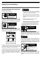
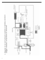
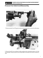
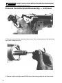
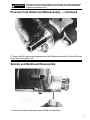
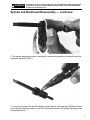
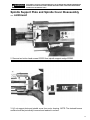
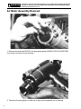
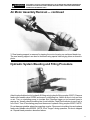
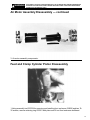
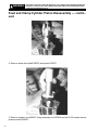
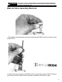
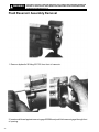
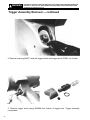
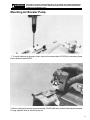
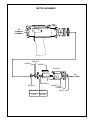
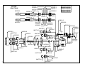
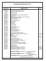
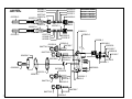
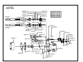
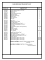
Operation & Service Manual
823111
2/01
15QNPD-D & 15QNPDF-D
NUTPLATE DRILL
Recoules Operation
Zone industrielle - B.P. 28
Avenue Maurice Chevalier
77831 Ozoir-la-Ferriere Cedex France
1
Safety Recommendations
For your safety and the safety of others, read and understand
the safety recommendations and operating instructions before operating any drill motor.
!
• Before the tool is connected to the air supply, the throttle
should be checked for proper operation (i.e., throttle valve
moves freely and returns to closed position).
Always wear protective equipment:
!
WARNING
• Before removing a tool from service or changing drill bits,
make sure the air line is shut off and drained of air. This will
prevent the tool from operating if the throttle is accidently
engaged.
Impact resistant eye protection
must be worn while operating
or working near this tool.
For additional information on eye protection, read the latest edition
of ANSI Z87.1, Occupational and Educational Eye and Face
Protection. This standard is available from the American National
Standards Institute, Inc., 11 West 42nd Street, New York, N.Y.
10036.
!
CAUTION
CAUTION
• Cutting tools used with these drill motors are sharp.
Handle them carefully to avoid injury.
• The collet and mandrel must be inserted into a properly
sized pre-drilled hole before starting the tool. An improperly sized pre-drilled hole prevents the mandrel from
engaging the collet and could result in slippage of the tool.
An improperly selected collet and mandrel can also result
in slippage of the tool.
Personal hearing protection is
recommended when operating
or working near this tool.
!
Hearing protection is recommended in high noise areas (above
85dBA). Close proximity of additional tools, reflective surfaces,
process noises, etc., can contribute substantially to the sound
level experienced by the operator.
!
WARNING
Wear respirator where
necessary.
Drilling or other use of this tool may produce hazardous fumes
and/or dust. To avoid adverse health effects, utilize adequate
ventilation and/or a respirator. Read the material safety data
sheet of any cutting fluids or materials involved in the drilling
process.
!
Do not wear loose fitting clothes,
long hair, gloves, ties or jewelry.
Follow good machine shop practices. Rotating shafts and moving
components entangle and entrap, and may result in serious
injuries. Never wear long hair, loose-fitting clothes, gloves, ties,
or jewelry when working with or near a drill of any type.
Quackenbush drills are designed to operate on 90psig (6.2 bar)
maximum air pressure using the proper size hose. Excessive air
pressure increases the loads and stresses on tool parts and drills,
and may result in breakage. The installation of a filter-regulatorlubricator in the air supply line ahead of the tool is highly recommended.
2
WARNING
CAUTION
Some non-ferrus metal chips (or dusts) are combustible. Examples: Aluminum, magnesium, Titanium, and Zirconium. See
the material safety data sheets for combustibility of materials
drilled. Never collect spark generating material with combustible
material. Examples: Collecting both steel and aluminum or steel
and titanium.
!
CAUTION
Slip and fall hazard.
Lubricant and coolant systems must
be properly maintained to avoid
leakage.
Hoses must be organized and care
taken to avoid tripping.
Quackenbush drills are often used with lubricant or cooling
systems which must be properly maintained to avoid leakage.
Failure to do so can result in serious injuries from slipping on oily
surfaces.
Safety Recommendations
Due to the number and variety of
tooling applications, the user's methods engineering departments, ect.,
must consider any hazards that may
be associated with each specific application of this product and provide
adequate operator protection from
Keep hands away from
inadvertent contact with any moving
clamping and feed
components. The clamping and feed
mechanisms. Clamp
mechanisms of self-colleting drill momechanism moves when
tors are exposed for visibility and can
drilling and connecting
move when the air supply is conor removing air supply.
nected or disconnected. To avoid
injury, keep fingers and hands away from these areas when
handling or operating this tool.
!
WARNING
!
WARNING
Repetitive work motions can
injure your hands and arms.
The following recommendations will help reduce or moderate the
effects of repetitive work motions. The operator of any drill should:
• Use a minimum hand grip force consistent with proper control
and safe operation
• Keep body and hands warm and dry
• Avoid anything that inhibits blood circulation
— Smoking Tobacco
— Cold Temperatures
— Certain Drugs
Avoid
Extension
OK
Avoid
Neutral
Flexion
Avoid
Radial Deviation
OK
Avoid
Neutral
Ulnar Deviation
• Avoid awkward postures
• Keep wrists as straight as possible
• Interrupt work, activities, or rotate jobs to provide
periods free from repetitive work motions.
Safety Labels
WARNING
Exposure to vibration can
injure your hands and arms.
Some individuals are susceptible to disorders of the hands and
arms when exposed to vibration and/or tasks which involve
repetitive work motions. Those individuals predisposed to vasculatory or circulatory problems may be particularly susceptible.
Cumulative trauma disorders such as carpal tunnel syndrome and
tendinitis can be caused or aggravated by repetitious, forceful
exertions of the hands and arms. These disorders develop gradually over periods of weeks, months, and years. Tasks should be
performed in such a manner that the wrists are maintained in a
neutral position, which is not flexed, hyperextended, or turned side
to side. Stressful postures should be avoided and can be controlled through tool selection and work location.
Any tool operator should be aware of the following warning signs
and symptoms so that a problem can be addressed before it
becomes a debilitating injury. Any user suffering from prolonged
symptoms of tingling, numbness, blanching of fingers, clumsiness
or weakened grip, inability to hold objects, nocturnal pain in the
hand, or any other disorder of the shoulders, arms, wrists, or
fingers should notify their employer so that a review of what steps
might be taken to prevent further occurances. These steps might
include but are not limited to, repositioning the workpiece or
redesigning the workstation, reassigning tool users to other jobs,
rotating jobs, changing worker pace, and/or changing the type of
tool used so as to minimize stress on the operator. Some tasks
may require more than one type of tool to obtain the optimum
operator/ tool/ task relationship.
The safety labels found on this tool are an essential part of this
product. Labels should not be removed. Labels should be checked
periodically for legibility. Replace safety labels when missing or
when the information can no longer be read. Replacement labels
can be ordered by the part numbers shown on this page.
!
WARNING
624241
Keep hands away from
clamping and feed
mechanisms. Clamp
mechanism moves when
drilling and connecting
or removing air supply.
203780
!
WARNING
• Wear impact resistant eye protection.
• Hearing protection is recommended.
• Wear respirator as necessary.
• Avoid contact with rotating spindle
and cutter.
• Exposure to repetitive work motion
and/or vibration may be harmful
to your hands and arms.
203780-2
!
203245
OPERATING
INSTRUCTIONS
!
CAUTION
Read operating
instructions before
operating tool.
3
Table of Contents
Safety Recommendations
2&3
Major Tool Component Nomenclature
4
Introduction and General Information
5
Air Logic
6 Thru 8
Disassembly Section
9 Thru 26
Exploded Views and Parts List
27 Thru 38
Trouble Shooting
Major Tool Component Nomenclature
4
39
Introduction and General Information
The Q-Matic nut plate drill motor has been developed for
drilling an countersinking the two holes required for attachment of nut plate fasteners.
Utilizing an air/hydraulic system, and expanding collet grips
the work with 240 lbs. holding force during the complete drilling
and countersinking operation.
The air powered motor develops 1HP and consumes 35 CFM
at 90 psi, the recommended air line pressure. The tool developes
200 lbs. of drilling thrust, and is capable of drilling holes up to
.128 in. diameter in aluminum. Total feed stroke is .562 in.;
maximum colleting stroke is .400 in.
Each Q-matic nut plate drill can be used to drill holes for all
three types of nut plate fasteners: single wing, double wing and
Mickey Mouse. By simply changing the front bearing support
block, lift finger and pressure foot, one tool can be used for all
types of nut plate fasteners. This feature eliminates the need
for a specific tool to drill and countersink the varied nut plate
configuration.
Depth Control
Individual spindle adjustment knobs located at the rear of the
tool controls the countersink depth accuracy to within + or .001 in.
Depending upon the hardness of the material being drilled,
drilling cycle time can be adjusted from 1.5 sec. to 34 sec. by
means of an externally mounted feed control valve.
The Q-Matic nut plate drill is available in three speed models:
600 rpm, 6,000 rpm and 20,000 rpm. An adjustable throttle
control valve located in the handle enables the tool spindle
speed to be reduced as much as 50%, allowing the tool rpm to
be matched to the material being drilled, thereby providing
optimum drill bit life.
An optional externally mounted pneumatic booster pump is
available for use on the 600 rpm models. This optional pump
increases both thrust and clamping force of the tool by as much
as two and one-half times.
Tool Start-Up
The Q-Matic nut plate drill motor is shipped from the factory
equipped to the customer's specifications; spindle RPM, nut
plate styles, drill spindle spacing and optional booster pump (if
needed). Collets, mandrels and drills can be supplied for
customers with start-up nut plate drilling applications.
After unpacking, examine the customer specified equipment
on the Q-Matic tool to verify style and size of components.
Attach air line to 1/4" NPT inlet bushing. If 1/4" quick disconnect plugs are minimum recommended size for standard units
and 3/8" quick disconnect fittings are minimum recommended
size for units with booster pumps, the recommended air hose
size is 3/8" inside diameter equipped with in-line filter and
lubricator.
With air line attached, pull trigger to start tool and allow tool to
run through a full cycle with drills in fully extended position.
When trigger is released, drills return to original position and
collet extends to open position.
To adjust depth of countersink, turn the spindle adjusting
knobs at the rear of the tool to the appropriate depth. Turning
the knobs counterclockwise reduces depth; clockwise increases depth.
Testing the tool on a separate piece of material will insure that
the tool is operating properly and that the countersink depth
has been accurately set.
Use a conventional drill to drill the pilot hole in the material. The
size of this pilot hole should match the diameter of the collet
and mandrel selected for the tool.
Insert the collet in the pilot hole while holding the pressure foot
firmly against the surface to be drilled, and actuate the trigger.
The collet will retract and clamp the tool firmly against the work
while the two drills will begin feeding into the material. The
drilling cycle is complete when the drills have reached the
maximum pre-set depth. Releasing the trigger will cause the
drills to retract and the collet to release.
The tool is now ready to begin another cycle.
Tool Operation
Optimum performance of the Q-Matic nut plate drill motor
requires a supply of clean, 90 psi air at 35 cfm. Using an in-line
lubricator will provide the proper lubrication for the air motor
and will significantly increase tool life expectancy.
Because O-rings are extensively used to seal systems within
the tool, the elimination of foreign particles and other contaminants will reduce the possibility of damage to these parts.
Always inspect O-rings for damage or wear, and replace as
required. The use of silicone O-ring lubricant is strongly
recommended during reasembly. The addition of oil in the air
line will also increase motor and valve life as well as the life of
the O-rings.
5
6
7
8
!
WARNING
DISCONNECT AIR SUPPLY BEFORE SERVICING. THE CLAMPING AND FEED MECHANISMS ARE
EXPOSED.TO AVOID INJURY, KEEP FINGERS AND HANDS AWAY FROM THESE AREAS WHEN
HANDLING OR OPERATING TOOLS.
Pressure Foot Attachment/Disassembly
1. Remove mandrel from lift finger by turning counterclockwise then remove the collet spring.
2. Remove the drills from spindles by holding spindles with an adjustable wrench on the flats
of the spindles. Insert pin-type tool into hole provided in drill shank and turn drill counterclockwise.
9
!
WARNING
DISCONNECT AIR SUPPLY BEFORE SERVICING. THE CLAMPING AND FEED MECHANISMS ARE
EXPOSED.TO AVOID INJURY, KEEP FINGERS AND HANDS AWAY FROM THESE AREAS WHEN
HANDLING OR OPERATING TOOLS.
Pressure Foot Attachment/Disassembly — continued
3. Remove pressure foot by loosening clamp screw, then unscrew pressure foot attachment
from collet closing piston rod.
4. Remove socket head cap screw 622060 from collet closing piston rod with hex wrench.
10
!
WARNING
DISCONNECT AIR SUPPLY BEFORE SERVICING. THE CLAMPING AND FEED MECHANISMS ARE
EXPOSED.TO AVOID INJURY, KEEP FINGERS AND HANDS AWAY FROM THESE AREAS WHEN
HANDLING OR OPERATING TOOLS.
Pressure Foot Attachment/Disassembly — continued
5. Retract collet lift finger by applying pressure on the lift finger toward the tool. Remove lift finger
from collet closing piston rod.
Spindle and Backhead Disassembly
1. Remove four socket head cap screws 863408 from backhead.
11
!
WARNING
DISCONNECT AIR SUPPLY BEFORE SERVICING. THE CLAMPING AND FEED MECHANISMS ARE
EXPOSED.TO AVOID INJURY, KEEP FINGERS AND HANDS AWAY FROM THESE AREAS WHEN
HANDLING OR OPERATING TOOLS.
Spindle and Backhead Disassembly — continued
2. Remove backhead and spindle assemblies from motor housing. NOTE: Four idler gears are
held in position by idler gear shafts in the backhead, and are retained by front bearing plate
622090. Front bearing plate remains in place in motor housing bore.
3. To remove spindles from backhead, use small punch to drive out roll pin 613162 in
adjustment knob 622094. Removal of the roll pin releases the adjustment knob from the spindle
adjustment screw 622093, the adjustment drive ring 622095 and spring 622140.
12
!
WARNING
DISCONNECT AIR SUPPLY BEFORE SERVICING. THE CLAMPING AND FEED MECHANISMS ARE
EXPOSED.TO AVOID INJURY, KEEP FINGERS AND HANDS AWAY FROM THESE AREAS WHEN
HANDLING OR OPERATING TOOLS.
Spindle and Backhead Disassembly — continued
4. The spindle adjustment screw is removed by screwing the spindle clockwise through the
backhead assembly 622091.
5. To remove spindle from spindle adjusting screw, remove retaining ring 623685 and insert
end of spindle adjusting screw in vise. With a soft face hammer, tap spindle adjusting screw
and pull spindle out.
13
!
WARNING
DISCONNECT AIR SUPPLY BEFORE SERVICING. THE CLAMPING AND FEED MECHANISMS ARE
EXPOSED.TO AVOID INJURY, KEEP FINGERS AND HANDS AWAY FROM THESE AREAS WHEN
HANDLING OR OPERATING TOOLS.
Spindle and Backhead Disassembly — continued
6. Double row ball bearings 863582 are removed from spindle shaft by removing lock nut
623767 and driving shaft through bearings. To remove spindle gear 622097, remove retaining
ring 833774 and slide spindle gear off shaft. Gear is held in place with key 622057. NOTE:
Examine gears carefully for wear before reassembling tool. Replace if worn.
Spindle Support Plate and Spindle Cover Disassembly
1. Remove button head screw 812962 and 622063 from front and rear of spindle cover 622124.
14
!
WARNING
DISCONNECT AIR SUPPLY BEFORE SERVICING. THE CLAMPING AND FEED MECHANISMS ARE
EXPOSED.TO AVOID INJURY, KEEP FINGERS AND HANDS AWAY FROM THESE AREAS WHEN
HANDLING OR OPERATING TOOLS.
Spindle Support Plate and Spindle Cover Disassembly
— continued
2. Remove two button head screws 622059 from spindle support wedge 622082.
3. Lift out support plate and spindle cover from motor housing. NOTE: The sintered bronze
muffler should be periodically removed and washed in solvent.
15
!
WARNING
DISCONNECT AIR SUPPLY BEFORE SERVICING. THE CLAMPING AND FEED MECHANISMS ARE
EXPOSED.TO AVOID INJURY, KEEP FINGERS AND HANDS AWAY FROM THESE AREAS WHEN
HANDLING OR OPERATING TOOLS.
Air Motor Assembly Removal
1. Remove the gear plate 622101 and gear plate spacer 624354 (6,000 & 20,000 RPM
tools only) from rear of motor housing.
2. Tap motor housing gently on table top to drop motor assembly out of housing.
16
!
WARNING
DISCONNECT AIR SUPPLY BEFORE SERVICING. THE CLAMPING AND FEED MECHANISMS ARE
EXPOSED.TO AVOID INJURY, KEEP FINGERS AND HANDS AWAY FROM THESE AREAS WHEN
HANDLING OR OPERATING TOOLS.
Air Motor Assembly Removal — continued
3. Rear bearing support is removed by tapping the motor housing on cushioned bench top.
The rear bearing support can also be removed using special internal grip pliers as shown in
photo.
Hydraulic System Bleeding and Filling Procedure
Attach hydraulic bleed unit to hydraulic fill fitting using hydraulic fitting coupler 622871. Remove
feed control needle valve 622026 and screw in circulating line. Attach air line to tool and turn
on air. Turn on circulating pump to circulate fluid. Depress trigger on tool several times to
remove air. Visually check circulating line for air bubbles. Check fluid indicator to see if tool is
full of fluid. Turn off circulating pump and disconnect hydraulic fitting coupler 622871 NOTE:
Do not damage spindles when disconnecting coupler. Disconnect circulating line and replace
feed control needle valve 622026. NOTE: If tool "lunges" during operation, it is due to trapped
air. Repeat bleed procedure described above.
17
!
WARNING
DISCONNECT AIR SUPPLY BEFORE SERVICING. THE CLAMPING AND FEED MECHANISMS ARE
EXPOSED.TO AVOID INJURY, KEEP FINGERS AND HANDS AWAY FROM THESE AREAS WHEN
HANDLING OR OPERATING TOOLS.
Air Motor Assembly Disassembly
1. Lift front bearing plate 622090 from alignment pin 812164.
2. Unscrew button head screw 615641 from rotor to remove rear bearing plate 864232. Remove
rotor 622089 from cylinder 864236. Use small flat blade screwdriver to pry up bearing cap
864335. Four rotor blades will fall out. NOTE: When reassembling rotor blades in rotor slots,
the straight edge of blade should be aligned with the outside diameter of the rotor.
18
!
WARNING
DISCONNECT AIR SUPPLY BEFORE SERVICING. THE CLAMPING AND FEED MECHANISMS ARE
EXPOSED.TO AVOID INJURY, KEEP FINGERS AND HANDS AWAY FROM THESE AREAS WHEN
HANDLING OR OPERATING TOOLS.
Air Motor Assembly Disassembly — continued
3. Air motor assembly components.
Feed and Clamp Cylinder Piston Disassembly
1.Using assembly tool 623334 for removing and installing front enclosure 624290 and two 1032 screws, remove retaining ring 622061 with pliers and lift out front enclosure bulkhead.
19
!
WARNING
DISCONNECT AIR SUPPLY BEFORE SERVICING. THE CLAMPING AND FEED MECHANISMS ARE
EXPOSED.TO AVOID INJURY, KEEP FINGERS AND HANDS AWAY FROM THESE AREAS WHEN
HANDLING OR OPERATING TOOLS.
Feed and Clamp Cylinder Piston Disassembly — continued
2. Remove clamp feed shaft 622072 and piston 622070.
3. Remove retainer ring 622065. Using assembly tool 623334 and two 8-32 screws remove
pressure head 624289.
20
!
WARNING
DISCONNECT AIR SUPPLY BEFORE SERVICING. THE CLAMPING AND FEED MECHANISMS ARE
EXPOSED.TO AVOID INJURY, KEEP FINGERS AND HANDS AWAY FROM THESE AREAS WHEN
HANDLING OR OPERATING TOOLS.
Main Air Valve Assembly Removal
1. Set handle in vertical position and remove inlet bushing 622080, then lift out main air valve
spring 622141.
2. Insert 8-32 screw into pilot spool 622007 and lift out pilot sleeve spacer 622081. Remove
spool and pilot sleeve. Main air valve assembly components are shown on right.
21
!
WARNING
DISCONNECT AIR SUPPLY BEFORE SERVICING. THE CLAMPING AND FEED MECHANISMS ARE
EXPOSED.TO AVOID INJURY, KEEP FINGERS AND HANDS AWAY FROM THESE AREAS WHEN
HANDLING OR OPERATING TOOLS.
Fluid Reservoir Assembly Removal
1. Remove hydraulic fill fitting 621762 from front of reservoir.
2. Insert small dowel against reservoir gage 622084 and push fluid reservoir gage through front
of opening.
22
!
WARNING
DISCONNECT AIR SUPPLY BEFORE SERVICING. THE CLAMPING AND FEED MECHANISMS ARE
EXPOSED.TO AVOID INJURY, KEEP FINGERS AND HANDS AWAY FROM THESE AREAS WHEN
HANDLING OR OPERATING TOOLS.
Fluid Reservoir Assembly Removal — continued
3. Push gage tube guide with dowel through front opening and remove from rear of housing.
NOTE: Always replace with new O-rings.
Trigger Assembly Removal
1. Remove set screw 622054 from trigger 622073 and pull trigger spool out of trigger spool
623691.
23
!
WARNING
DISCONNECT AIR SUPPLY BEFORE SERVICING. THE CLAMPING AND FEED MECHANISMS ARE
EXPOSED.TO AVOID INJURY, KEEP FINGERS AND HANDS AWAY FROM THESE AREAS WHEN
HANDLING OR OPERATING TOOLS.
Trigger Assembly Removal — continued
2. Remove snap ring 864271 and pull trigger sleeve and trigger spool 623691 out of base.
3. Remover trigger return spring 622088 from bottom of trigger bore. Trigger assembly
components.
24
!
WARNING
DISCONNECT AIR SUPPLY BEFORE SERVICING. THE CLAMPING AND FEED MECHANISMS ARE
EXPOSED.TO AVOID INJURY, KEEP FINGERS AND HANDS AWAY FROM THESE AREAS WHEN
HANDLING OR OPERATING TOOLS.
Mounting Air Booster Pump
1. To install optional air booster pump, remove the comer plate 621439 by unscrewing three
button head screws 622053.
2. Mount optional air booster pump assembly 621482 with three socket head cap screws and
O-rings supplied with air booster pump kit.
25
!
WARNING
DISCONNECT AIR SUPPLY BEFORE SERVICING. THE CLAMPING AND FEED MECHANISMS ARE
EXPOSED.TO AVOID INJURY, KEEP FINGERS AND HANDS AWAY FROM THESE AREAS WHEN
HANDLING OR OPERATING TOOLS.
Mounting Air Booster Pump — continued
3. NOTE: The booster pump is recommended for use only in the 600 rpm model tool.
Feed Control Valve Removal
1. Using hex wrench, unscrew feed control needle valve part 622026. Remove from housing
and replace O-ring 844301 to insure positive seal.
26
CLAMPING ASSEMBLY
624289-5
622065-1
622143-6
622065-1
622071-9
TO
MOTOR
844310-3
864737-2
622086-7
622061-0
622062-8
614902-5
624290-3
844265-9
SPECIFIED BY
CUSTOMER
622143-6
622070-1
622143-6
843518-2
622881-1
623811-7
614902-5
622060-2
622127-9
843518-2
622881-1
844265-9
622072-7
622065-1
622143-6
SPECIFIED BY
CUSTOMER
625873-5
616514-6 .1875 I.D.
616302-6 .2500 I.D.
SPECIFIED BY
CUSTOMER
203210-0
625873-5
SPECIFIED BY
CUSTOMER
27
CLAMPING ASSEMBLY PARTS LIST
MODEL NO.
203210-0
614902-5
616302-6
616514-6
622060-2
622061-0
622062-8
622065-1
622070-1
622071-9
622072-7
622086-7
622127-9
622143-6
622881-1
623811-7
624289-5
624290-3
625873-5
843518-2
844265-9
844310-3
864737-2
28
NAME OF PART
Foot Guard
Piston Retainer Ring
Pressure Foot Bushing .2500 I.D.
Pressure Foot Bushing .1875 I.D.
Lift Finger Screw
Front Enclosure Retainer Ring
"O"-Ring 13/16" x 1-1/16"
Pressure Head Retainer Ring
Piston
Collet Piston
Clamp Feed Shaft
Rear Bearing Plate Support
"O"-Ring 1-3/8" x 1-9/16"
"O"-Ring 1-13/16" x 2"
"O"-Ring 55/64" x 1-9/64"
Set Screw
Pressure Head
Front Enclosure
Foot Guard Screw
Front Enclosure Set Screw
Front Enclosure Ball (1/8" Dia.)
"O"-Ring 1/2" x 11/16"
"O"-Ring 1-7/8" x 2"
QTY.
1
2
2
2
1
1
1
3
1
1
1
1
1
3
2
1
1
1
2
2
2
1
2
HANDLE ASSEMBLY
622085-9
622084-2
844304-6
ADD
FLUID
844303-8
621762-4
844304-6
812962-9
622063-6
203246-4
622124-6 - Regular
622669-0 - Large
622059-4
Regular
Model Only
624241-6
622082-6
Regular
Model Only
622087-5
622064-4
622055-2
616302-6
844301-2
622026-3
843434-2
621439-9
623691-3
622073-5
622053-7
844301-2
622054-5
864271-2
622064-4
847710-1
Specified by
Customer Regular
Model Only
622088-3
203762-0
844306-1
622067-7 - Regular
Specified by
Customer - Large
844301-2
621385-4
622080-0
844312-9
622081-8
622079-2
625130-0
622078-4
619656-2
847710-1
863454-5
622141-0
29
HANDLE ASSEMBLY PARTS LIST
MODEL NO.
203246-4
203762-0
616302-6
619656-2
621385-4
621439-9
621762-4
622026-3
622053-7
622054-5
622055-2
622059-4
622063-6
622064-4
622067-7
622073-5
622078-4
622079-2
622080-0
622081-8
622082-6
622084-2
622085-9
622087-5
622088-3
622124-6
622141-0
622669-0
623691-3
624241-6
625130-0
812962-9
843434-2
844301-2
844303-8
844304-6
844306-1
844312-9
847710-1
863454-5
864271-2
NAME OF PART
Warning Label
Grip Sleeve
Support Block Bushing
Shift Piston Screw
Pilot Valve Assembly
Cover Assembly
Filler Check Assembly (includes 844303, 844304)
Needle Valve
Cover Assembly Screw
Trigger Set Screw
Spindle Thrust Bushing (included in 622067)
Support Wedge Screw
Spindle Cover Screw (Small)
Spindle Needle Bearing (included in 622067)
QNPD-D Handle (includes 622055, 622064)
Trigger
Shift Piston
Adjustment Screw
Inlet Bushing
Pilot Sleeve Bushing
Support Wedge
Reservoir Gage
Gage Tube Guide
Muffler Pad
Trigger Spring
Spindle Cover (QNPD-D)
Inlet Spring
Spindle Cover (QNPD-D)
Trigger Valve Assembly
Warning Label
Swivel Fitting Coupler
Spindle Cover Screw (Large)
Handle Pipe Plug
"O"-Ring 1/8" x 1/4"
"O"-Ring 3/16" x 5/16"
"O"-Ring 7/32 x 11/32"
"O"-Ring 5/16" x 7/16"
"O"-Ring 5/8" x 11/16"
"O"-Ring 1/2" x 5/8"
"O"-Ring 9/16" x 11/16"
Trigger Snap Ring
OPTIONAL ACCESSORY
HYDRAULIC FITTING COUPLER — 622871-2
30
QTY.
1
1
4
1
1
1
1
1
3
1
2
2
1
4
1
1
1
1
1
1
1
1
1
1
1
1
1
1
1
1
1
1
1
3
3
4
2
1
3
3
1
MOTOR ASSEMBLY
TO
CLAMPING
ASSEMBLY
847095-7
615641-8
864234-0
812164-2
TO
GEAR TRAIN
622089-1
843913-5
864335-5
600 & 6000 864232-4
20,000
864236-5
622090-9
847511-3
622758-1
31
MOTOR ASSEMBLY PARTS LIST
MODEL NO.
615641-8
622089-1
622090-9
622758-1
812164-2
843913-5
847095-7
847511-3
864232-4
864234-0
864236-5
864335-5
32
NAME OF PART
Rear Bearing Retainer Screw
Rotor
Front Bearing Plate
Rear Bearing Plate 20,000 RPM (Left Hand Rotation)
Cylinder Roll Pin
Rotor Collar
Rear Rotor Ball Bearing
Front Rotor Ball Bearing
Rear Bearing Plate 600 & 6,000 RPM (Right Hand Rotation)
Rotor Blade
Cylinder
Motor Bearing Cap
QTY.
1
1
1
1
2
1
1
1
1
4
1
1
623766-3
623765-5*
863582-3
623767-1
622093-2
863582-3
623685-5
833774-3
622097-4
600 RPM
GEAR TRAIN
622057-8
622097-4
623767-1
622057-8
833774-3
623685-5
863582-3
623766-3
844774-0
622102-2
844774-0
622103-0
842654-6
622105-5
613126-2
622106-3
842654-6
615553-5
622103-0
622093-2
619816-2
203245-6
863582-3
623765-5*
622100-6
* OPTIONAL SHIMS
864730-7- .001 Opt.
864731-5- .002 Opt.
864732-3- .005 Opt.
623765-5- .006 Std.
622094-1
622140-2
622095-8
613162-7
622142-8
844799-7
613162-7
844774-0
622104-8
844799-7
622142-8
622100-6
622095-8
622140-2
622094-1
847688-9
847609-1
622101-4 622100-6
625872-7
844774-0
844774-0
844799-7
622142-8
622091-7
619816-2
844799-7
844774-0
33
622142-8
622100-6
600 RPM GEAR TRAIN PARTS LIST
MODEL NO.
203245-6
613126-2
613162-7
615553-5
619816-2
622057-8
622091-7
622093-3
622094-1
622095-8
622097-4
622100-6
622101-4
622102-2
622103-0
622104-8
622105-5
622106-3
622140-2
622142-8
623685-5
623765-5
623766-3
623767-1
625872-7
813162-7
833774-3
842654-6
844774-0
844799-7
847609-1
847688-9
863582-3
864730-7
864731-5
864732-3
NAME OF PART
Caution Label (included in 622091)**
Gear Pinion Spur Retainer Ring
Spindle Roll Pin*
Carrier Bearing
Backhead Dowel Pin (included in 622091)**
Spindle Key*
Backhead (includes 202903, 619816, 847609)
Spindle Adjustment Screw*
Adjustment Knob
Adjustment Drive Ring
Spindle Gear*
Idler Gear
Gear Plate
Internal Gear
Planet Wheel
Planet Carrier Spacer
Planet Carrier
Gear Pinion Spur
Adjustment Knob Spring
Idler Gear Spacer
Spindle Bearing Retainer Ring*
Spindle Bearing Spacer .006" (Standard)*
Spindle*
Spindle Lock Nut*
Wavy Washer
Spindle Retainer Pin
Spindle Gear Retainer Ring*
1st Reduction Spider Idler Gear Pin
Idler Gear Bearing
Idler Gear Pin (4 included in 622091)**
Backhead Bearing (inclued in 622091)**
Backhead Bolt
Spindle Bearing*
Spindle Bearing Spacer .001" (Opt.)
Spindle Bearing Spacer .002" (Opt.)
Spindle Bearing Spacer .005" (Opt.)
SPINDLE ASSEMBLY — 621445-6 — * Parts included in Spindle
Assembly.
BACKHEAD ASSEMBLY — 622091-7 — **Parts included in
Backhead Assembly
CONVERSION KIT — 600 RPM to 6000 RPM — 621446-4
6000 RPM to 600 RPM — 621447-2
34
QTY.
1
1
2
1
2
2
1
2
2
2
2
4
1
1
2
1
1
1
2
4
2
Variable
2
2
Variable
2
2
2
6
4
1
4
2
Variable
Variable
Variable
623766-3
623765-5*
863582-3
623767-1
622093-2
863582-3
623685-5
833774-3
622097-4
6,000 RPM
GEAR TRAIN
622057-8
622097-4
623767-1
622057-8
833774-3
623685-5
863582-3
623766-3
622093-2
619816-2
203245-6
863582-3
623765-5*
622100-6
844774-0
* OPTIONAL SHIMS
864730-7- .001 Opt.
864731-5- .002 Opt.
864732-3- .005 Opt.
623765-5- .006 Std.
622094-1
622140-2
622095-8
613162-7
622142-8
844799-7
622095-8
613162-7
844774-0
624354-7
622100-6
622099-0
622101-4
625872-7
844774-0
844799-7
622142-8
622140-2
622094-1
847688-9
847609-1
622100-6
844799-7
622142-8
622091-7
619816-2
844799-7
844774-0
35
622142-8
622100-6
6,000 RPM GEAR TRAIN PARTS LIST
MODEL NO.
203245-6
613162-7
619816-2
622057-8
622091-7
622093-3
622094-1
622095-8
622097-4
622099-0
622100-6
622101-4
622140-2
622142-8
623685-5
623765-5
623766-3
623767-1
624354-7
625872-7
813162-7
833774-3
844774-0
844799-7
847609-1
863582-3
864730-7
864731-5
864732-3
NAME OF PART
Caution Label (included in 622091)**
Spindle Roll Pin*
Backhead Dowel Pin (included in 622091)**
Spindle Key*
Backhead (includes 202903, 619816, 847609)
Spindle Adjustment Screw*
Adjustment Knob
Adjustment Drive Ring
Spindle Gear*
Pinion Gear
Idler Gear
Gear Plate
Adjustment Knob Spring
Idler Gear Spacer
Spindle Bearing Retainer Ring*
Spindle Bearing Spacer .006" (Standard)*
Spindle*
Spindle Lock Nut*
Gear Plate Spacer
Wavy Washer
Spindle Retainer Pin
Spindle Gear Retainer Ring*
Idler Gear Bearing
Idler Gear Pin
Backhead Bearing (included in 622091)**
Spindle Bearing*
Spindle Bearing Spacer .001" (Opt.)
Spindle Bearing Spacer .002" (Opt.)
Spindle Bearing Spacer .005" (Opt.)
SPINDLE ASSEMBLY — 621445-6 — *Parts included in Spindle
Assembly.
BACKHEAD ASSEMBLY — 622091-7 — **Parts included in
Backhead Assembly
CONVERSION KIT — 600 RPM to 6000 RPM — 621446-4
6000 RPM to 600 RPM — 621447-2
36
QTY.
1
2
2
2
1
2
2
2
2
1
4
1
2
4
2
Variable
2
2
1
Variable
2
2
4
4
1
2
Variable
Variable
Variable
20,000 RPM
GEAR TRAIN
623765-5*
863582-3
623767-1
622093-2
863582-3
623685-5
833774-3
622097-4
623766-3
622057-8
622097-4
833774-3
623685-5
863582-3
623766-3
619816-2
203245-6
863582-3
623765-5*
622142-8
844799-7
622100-6
844774-0
624354-7
622093-2
623767-1
622057-8
* OPTIONAL SHIMS
864730-7- .001 Opt.
864731-5- .002 Opt.
864732-3- .005 Opt.
623765-5- .006 Std.
622094-1
622140-2
622095-8
613162-7
622095-8
613162-7
844774-0
622100-6
622101-4
625872-7
844799-7
622142-8
847688-9
847609-1
623756-4
623751-5
622140-2
622094-1
623754-9
619816-2
623751-5
37
20,000 RPM GEAR TRAIN PARTS LIST
MODEL NO.
203245-6
613162-7
622057-8
622093-3
622094-1
622095-8
622097-4
622099-0
622100-6
622101-4
622140-2
622142-8
623685-5
623751-5
623756-4
623765-5
623766-3
623767-1
624354-7
625872-7
833774-3
844774-0
844799-7
847609-1
863582-3
864730-7
864731-5
864732-3
NAME OF PART
Caution Label (included in 623754)**
Spindle Roll Pin*
Spindle Key*
Spindle Adjustment Screw*
Adjustment Knob
Adjustment Drive Ring
Spindle Gear*
Pinion Gear Spur
Idler Gear
Gear Plate
Adjustment Knob Spring
Idler Gear Spacer
Spindle Bearing Retainer Ring*
Backhead Plug (included in 623754)**
Pinion Gear
Spindle Bearing Spacer .006" (Standard)*
Spindle*
Spindle Lock Nut*
Gear Plate Spacer
Wavy Washer
Spindle Gear Retainer Ring*
Idler Gear Bearing
Idler Gear Pin (included in 623754)**
Backhead Bearing (included in 623754)**
Spindle Bearing*
Spindle Bearing Spacer .001" (Opt.)
Spindle Bearing Spacer .002" (Opt.)
Spindle Bearing Spacer .005" (Opt.)
SPINDLE ASSEMBLY — 621445-6 — *Parts included in Spindle
Assembly.
BACKHEAD ASSEMBLY — 623754-9 — **Parts included in
Backhead Assembly
38
QTY.
1
2
2
2
2
2
2
1
2
1
2
2
2
2
1
Variable
2
2
1
Variable
2
2
2
1
2
Variable
Variable
Variable
TROUBLESHOOTING GUIDE FOR 15 NUT PLATE DRILL MOTOR
SYMPTOM
REASON
SOLUTION
Air motor and/or clamp and feed functions do not start when trigger is depressed.
Trigger or pilot valves clogged with foreign matter.
Disconnect air line then remove trigger
and pilot valves and inspect for debris.
Inspect "O"-rings and replace if necessary.
Air motor does not run when trigger is
depressed, but feed and clamp functions work properly.
Gears damaged or jammed with debris.
With air line disconnected from tool,
remove backhead, clean and inspect
hears for damage and check both
spindles for free rotation.
Foreign matter in motor inlet.
Remove motor and clean debris from
the motor inlet ports.
Motor throttle valve adjusted too far,
stopping air flow to motor.
Adjust valve until end of valve stem is
flush with the end of housing.
Broken rotor blades, rotor or gear bearings.
Remove motor and inspect rotor blades
and bearings. Replace if necessary.
Pilot valve sticky (not fully closed), or bad
"O"-rings on valve sleeve.
Remove and inspect valve for debris
and for free movement of valve spool.
Inspect "O"-rings, lubricate and reassemble.
Leaking "O"-ring on air motor rear bearing support.
Remove and inspect "O"-rings. Replace
if necessary and reassemble.
Feed control needle valve "closed".
Turn feed control needle valve counterclockwise until feed commences.
Debris in hydraulic system.
Remove feed control valve needle and
bleed hydraulic system until fluid is clear.
Air in hydraulic system.
If air in hydraulic system continues to be
a problem, remove the hydraulic reservoir piston and check or replace its "O"rings. Also check or replace the inner
and outer "O"-rings on the pressure head
located in the main cylinder.
Damaged or worn "O"-ring on collet piston.
Check or replace "O"-ring.
Air motor "idles" when trigger is released.
Motor runs and the tool clamps workpiece
but does not feed.
Tool lunges during feed or when drills
exit the far side of the workpiece or
variation in feed rate.
39
40