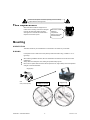
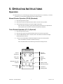
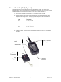
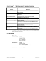
1
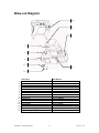
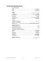
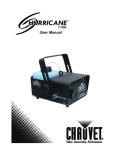
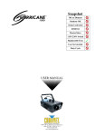
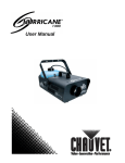
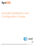
Hurricane™ 1100 Snapshot OK on Dimmer F-1100 Outdoor OK Sound Activated DMX512 Master/Slave 115V/230V Switch Replaceable Fuse User Serviceable Duty Cycle USER MANUAL 3000 N 29th Ct, Hollywood, FL 33020 U.S.A. (800) 762-1084 – (954) 929-1115 FAX (954) 929-5560 www.chauvetlighting.com TABLE OF CONTENTS 1. Before You Begin ................................................................................................................................ 2 What is included ....................................................................................................................................... 2 Unpacking Instructions .............................................................................................................................. 2 AC Power ................................................................................................................................................. 3 Safety Instructions .................................................................................................................................... 3 2. Introduction ......................................................................................................................................... 4 Features ................................................................................................................................................... 4 Product Dimensions .................................................................................................................................. 4 Product Overview...................................................................................................................................... 5 Fuse Replacement .................................................................................................................................... 6 Mounting .................................................................................................................................................. 6 Orientation ................................................................................................................................................ 6 Rigging ..................................................................................................................................................... 6 5. Operating Instructions ........................................................................................................................ 7 Operation ................................................................................................................................................. 7 Manual Remote Operation (FC-M) ............................................................................................................. 7 Timer Remote Operation (FC-T) ................................................................................................................ 7 Wireless Controller (FC-W)........................................................................................................................ 8 Contact Us................................................................................................................................................ 9 6. Appendix ........................................................................................................................................... 10 General Maintenance .............................................................................................................................. 10 Returns Procedure .................................................................................................................................. 10 Claims .................................................................................................................................................... 10 Blow-out Diagram. .................................................................................................................................. 11 Connections Drawing .............................................................................................................................. 12 Technical Specifications .......................................................................................................................... 13 1. BEFORE YOU BEGIN What is included 1 x Hurricane™ 1100 1 x FC-M Wired manual remote 1 x Warranty Card 1 x User Manual Unpacking Instructions Immediately upon receiving a fixture, carefully unpack the carton, check the contents to ensure that all parts are present, and have been received in good condition. Notify the shipper immediately and retain packing material for inspection if any parts appear damaged from shipping or the carton itself shows signs of mishandling. Save the carton and all packing materials. In the event that a fixture must be returned to the factory, it is important that the fixture be returned in the original factory box and packing. Hurricane™ 1100 User Manual 2 3/26/2009 3:17 PM AC Power To determine the power requirements for a particular fixture, see the label affixed to the back plate of the fixture or refer to the fixture’s specifications chart. A fixture’s listed current rating is its average current draw under normal conditions. All fixtures must be powered directly off a switched circuit and cannot be run off a rheostat (variable resistor) or dimmer circuit, even if the rheostat or dimmer channel is used solely for a 0% to 100% switch. Before applying power to a fixture, check that the source voltage matches the fixture’s requirement. Check the fixture or device carefully to make sure that if a voltage selection switch exists that it is set to the correct line voltage you will use. Safety Instructions Please read these instructions carefully, which includes important information about the installation, usage and maintenance of this product. Please keep this User Guide for future consultation. If you sell the unit to another user, be sure that they also receive this instruction booklet. Always make sure that you are connecting to the proper voltage, and that the line voltage you are connecting to is not higher than that stated on the decal or rear panel of the fixture. This product is intended for indoor use only! (If applicable) To prevent risk of fire or shock, do not expose fixture to rain or moisture. Make sure there are no flammable materials close to the unit while operating. The unit must be installed in a location with adequate ventilation, at least 20in (50cm) from adjacent surfaces. Be sure that no ventilation slots are blocked. Always disconnect from power source before servicing or replacing lamp or fuse and be sure to replace with same lamp source. Secure fixture to fastening device using a safety chain. Never carry the fixture solely by its head. Use its carrying handles. Maximum ambient temperature (Ta) is 104°F (40°C). Do not operate fixture at temperatures higher than this. In the event of a serious operating problem, stop using the unit immediately. Never try to repair the unit by yourself. Repairs carried out by unskilled people can lead to damage or malfunction. Please contact the nearest authorized technical assistance center. Always use the same type spare parts. Never connect the device to a dimmer pack. Make sure the power cord is never crimped or damaged. Never disconnect the power cord by pulling or tugging on the cord. Avoid direct eye exposure to the light source while it is on. Caution! There are no user serviceable parts inside the unit. Do not open the housing or attempt any repairs yourself. In the unlikely event your unit may require service, please contact CHAUVET at: 954-929-1115. Hurricane™ 1100 User Manual 3 3/26/2009 3:17 PM 2. INTRODUCTION Features Output: 8,000cfm 1.3L tank capacity Uses 1L every 21min (continuous use at full output) 5 minute heat up Manual fog button Low fluid indicator and auto shut down Wired remote included Water-based fogger Product Dimensions Hurricane™ 1100 User Manual 4 3/26/2009 3:17 PM Product Overview Hanging bracket Fluid container Safety cable eye bolt Tilt Adjustment knob Heater Nozzle Manual Fog button Low Fluid indicator Fluid level indicator Manual Controller Wireless Controller Power input (hardwired) Fuse holder Hurricane™ 1100 User Manual 5 3/26/2009 3:17 PM Disconnect the power cord before replacing a fuse and always replace with the same type fuse. Fuse Replacement With a flat head screwdriver wedge the fuse holder out of its housing. Remove the damaged fuse from its holder and replace with exact same type fuse. Insert the fuse holder back in its place and reconnect power. The fuse is located inside this compartment. Remove using a flat head screwdriver. Mounting O RI ENT AT I O N This fixture should only be mounted/used on a flat surface. This fixture may not be tilted. RI G G I NG It is important never to obstruct the vents’ pathways. Mount the fixture using, a suitable “C” or “O” type clamp. When selecting installation location, take into consideration the fluid reservoir access and routine maintenance. Safety cables must always be used, utilizing the provided safety eye bolt. Never mount in places where the fixture will be exposed to rain, high humidity, extreme temperature changes or restricted ventilation. Hanging Clamp Note! Clamp is sold separately. Hurricane™ 1100 User Manual Angled Down 6 Angled Up 3/26/2009 3:17 PM 5. OPERATING INSTRUCTIONS Operation This mode will allow you to control the fogger manually, set the fog machine to run continuously, or to set the fog machine to run off bursts with adjustable interval and duration settings. Manual Remote Operation (FC-M) (Standard) 1) Plug in the fog machine to power. 2) Plug in the M remote to the Manual Controller socket on the rear of the fog machine. 3) Press the single button located on the remote to trigger the fog output. Note: The button is momentary, which means that the fog machine will only output while the button is pressed. Once the button is released, the fog will stop outputting. Timer Remote Operation (FC-T) (Optional) 1) Plug in the fog machine to power. 2) Plug in the timer remote to the Manual Controller socket on the rear of the fog machine. 3) Press the TIMER ON/OFF button on the timer remote. The LED above the button should light, indicating activation of function. 4) You may now set the INTERVAL & DURATION adjustment knobs to the desired position. Note: The INTERVAL is the time in between bursts of fog. Note: The DURATION is the time that the fog machine will run during the burst. Interval Adjustment Duration Adjustment Timer LED Indicator Manual Momentary LED Manual/Power LED Indicator Manual control momentary button Timer latching button Hurricane™ 1100 User Manual Continuous latching button 7 3/26/2009 3:17 PM Wireless Controller (FC-W) (Optional) This mode will allow you to control the fogger using the optional wireless controller. This consists of the transmitter and the receiver. You may control up to 4 independent fog machines, or many more if you run them simultaneously. See the below instructions on setting up your fogger to operate with the FC-W. 1) Plug the wires receiver into the fog machine 5-pin port labeled “Wireless Controller”. 2) There are 4 buttons on the wireless remote transmitter which act as triggers. Each button can be assigned to a different fog machine. You may only choose 1 dipswitch on each receiver. See the below configuration for setting the receivers to operate with the transmitter remote. 3) Mode Dipswitches CH1 1 = On, 2-4 = Off CH2 2 = On, 1,3,4 = Off CH3 3 = On, 1,2,4 = Off CH4 4 = On, 1,2,3 = Off Press the fog button, and the fog machine will output fog momentarily for as long as you hold down the button. LED indicator (ready) LED indicator (heating) Dipswitches Wireless Transmitter Fog Triggers Hurricane™ 1100 User Manual Wireless Receiver 8 3/26/2009 3:17 PM Hurricane™ 1100 General Troubleshooting Symptom No Power No fog output Breaker/Fuse keeps blowing Low fog output Fog machine is not heating up Remote does not work Fluid indicator states no fog, but the container if full. Solution(s) Check mains power. Check external fuse. Check internal fuse. Check fluid level. Check remote. If using wireless, check batteries. If using wireless, check dipswitches on receiver. Possible electrical short. Contact Chauvet or a Chauvet Dealer/distributor for further instruction. Run a cleaning solution through the fog machine. Check that the fog machine is plugged into the correct voltage. Check the external fuse. Check the internal fuse. Possible bad part. Contact Chauvet or a Chauvet Dealer/distributor for further instruction. Make sure connector is firmly connected to device. Try using another controller. Possible bad controller. Check the internal fuse. Check the external fuse. Try resetting the fog machine by turning the power off, and then on again. Possible bad part. Contact Chauvet or a Chauvet Dealer/distributor for further instruction. If you still have a problem after trying the above solutions, please contact CHAUVET Technical Support at the location listed below. Contact Us Wor l d Wi de General Information CHAUVET th 3000 North 29 Court Hollywood, FL 33020 voice: 954.929.1115 fax: 954.929.5560 toll free: 800.762.1084 Technical Support CHAUVET th 3000 North 29 Court Hollywood, FL 33020 voice: 954.929.1115 (Press 4) fax: 954.929.5560 (Attention: Service) World Wide Web www.chauvetlighting.com Hurricane™ 1100 User Manual 9 3/26/2009 3:17 PM 6. APPENDIX General Maintenance To maintain optimum performance and minimize wear fixtures should be cleaned frequently. Usage and environment are contributing factors in determining frequency. As a general rule, fixtures should be cleaned at least twice a month. Dust build up reduces light output performance and can cause overheating. This can lead to reduced lamp life and increased mechanical wear. Be sure to power off fixture before conducting maintenance. Unplug fixture from power. Use a vacuum or air compressor and a soft brush to remove dust collected on external vents and internal components. Clean all glass when the fixture is cold with a mild solution of glass cleaner or Isopropyl Alcohol and a soft lint free cotton cloth or lens tissue. Apply solution to the cloth or tissue and drag dirt and grime to the outside of the lens. Gently polish optical surfaces until they are free of haze and lint. The cleaning of internal and external optical lenses and/or mirrors must be carried out periodically to optimize light output. Cleaning frequency depends on the environment in which the fixture operates: damp, smoky or particularly dirty surrounding can cause greater accumulation of dirt on the unit’s optics. Clean with soft cloth using normal glass cleaning fluid. - Always dry the parts carefully. - Clean the external optics at least every 20 days. Clean the internal optics at least every 30/60 days. Returns Procedure Returned merchandise must be sent prepaid and in the original packing, call tags will not be issued. Package must be clearly labeled with a Return Merchandise Authorization Number (RMA #). Products returned without a RMA # will be refused. Call CHAUVET and request a RMA # prior to shipping the fixture. Be prepared to provide the model number, serial number and a brief description of the cause for the return. Be sure to properly pack fixture, any shipping damage resulting from inadequate packaging is the customer’s responsibility. CHAUVET reserves the right to use its own discretion to repair or replace product(s). As a suggestion, proper UPS packing or double-boxing is always a safe method to use. Note: If you are given a RMA #, please include the following information on a piece of paper inside the box: 1) Your name 2) Your address 3) Your phone number 4) The RMA # 5) A brief description of the symptoms Claims Damage incurred in shipping is the responsibility of the shipper; therefore the damage must be reported to the carrier upon receipt of merchandise. It is the customer's responsibility to notify and submit claims with the shipper in the event that a fixture is damaged due to shipping. Any other claim for items such as missing component/part, damage not related to shipping, and concealed damage, must be made within seven (7) days of receiving merchandise. Hurricane™ 1100 User Manual 10 3/26/2009 3:17 PM Blow-out Diagram. 10 9 7 3 5 1 12 8 11 1 2 3 4 5 6 7 8 9 10 11 12 13 14 15 16 Description Master PCB 120V Master PCB 220V Heater 700W 550° Celsius 120V Heater 700W 550° Celsius 220V Pump 120V Pump 220V Fluid container 1.3 liters Fluid sensor Thermal switch 115° Celsius Bracket Knob Fuse holder Manual fog button Fuse 8A 250V Fluid filter Fluid hose with fittings Copper tubing with fittings Hurricane™ 1100 User Manual Part Number P170-F1MSPCB 220VP170-F1MSPCB P120-HT7 220VP120-HT7 P200-F1PUMP 220VP200-F1PUMP P70-F1FLC P170-F1FLOS P170-THEF11 P111-F1BKNOB P170-FUSEHOL P111-F1FOGB P170-FUSE008 P110-F1FLAS P170-F1RUB P170-F1COP 11 3/26/2009 3:17 PM Connections Drawing In the event that any part(s) may need to be replaced/repaired, you may use the below diagram to assist in this operation. Warning: All repairs should only be performed by Authorized Service Personnel. Hurricane™ 1100 User Manual 12 3/26/2009 3:17 PM Technical Specifications WEIGHT & DIMENSIONS Length ................................................................................................................................ 9.7 in (247 mm) Width .................................................................................................................................. 9.6 in (243 mm) Height ................................................................................................................................. 8.7 in (220 mm) Weight .................................................................................................................................. 8.3 lbs (3.8 kg) POWER AC Power ..................................................................................................... 120V 60Hz AC or 230V 50Hz Fuse (115V) ................................................................................................................................... 8A 250V Power Consumption ..........................................................................................774W (5.9A) max at 120V Inrush Power ........................................................................................................................ (6.5A) at 120V Power Factor........................................................................................................................... 0.99 at 120V Fuse (230V) ................................................................................................................................... 5A 250V Power Consumption .................................................................................... 722.2W (3.14A) max at 230V Inrush Power ...................................................................................................................... (3.14A) at 230V Power Factor........................................................................................................................... 0.99 at 230V THERMAL Maximum ambient temperature .............................................................................................104°F (40°C) CONTROL & PROGRAMMING Data input ............................................................................................5-pin & ground DIN5 female socket Data pin configuration......pin1(LED), pin2(control), pin3(+5V), pin4(ground), pin5(none), ground(none) ORDERING INFORMATION Hurricane™ 1100...............................................................................................................................F1100 Wired manual remote (included) ....................................................................................................... FC-M Wired timer remote (optional).............................................................................................................. FC-T Wireless manual remote (optional) ....................................................................................................FC-W SPARE PARTS ORDERING INFORMATION Master PCB....................................................................................................................... P170-F1MSPCB Heater ........................................................................................................................................ P120-HT7 Pump ................................................................................................................................... P200-F1PUMP Fluid container ........................................................................................................................ P170-F1FLC Fluid sensor ........................................................................................................................ P170-F1FLOS Thermal switch ......................................................................................................................P170-THEF11 Bracket knob ..................................................................................................................... P111-F1BKNOB Fuse holder ...................................................................................................................... P170-FUSEHOL Manual fog button ................................................................................................................P111-F1FOGB WARRANTY INFORMATION Warranty.................................................................................................................. 1-year limited warranty Hurricane™ 1100 User Manual 13 3/26/2009 3:17 PM