1
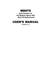
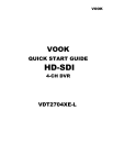
SMART CENTRE VIDEO INTERCOM SYSTEM USERS’ MANUAL VOOK INTELLIGENT TECHNOLOGY MANUAL CODE: VHD-M1743MX Contents INSTALLATION MANUAL Cover Contents 1 Installation Guide 2 Features & Specifications 3 Descriptions for Monitor 4 Descriptions for Doorbell/Camera 5 Wiring Diagrams and Schematics 6-11 Installation 12-13 OPERATION GUIDE Operation Guide 14 System Settings 15-19 Care Instructions 19 1 Installation Guide 2 FEATURES & SPECIFICATIONS Features Dual communication & Call Transfer Door Release Image capture (option without memory, 8 or 64 Pictures memory ) Picture memories with date and time By no answer, automaticly picture memory TV/MUSIC Playing CCTV Surveillance Supports 2 cameras and 8 Monitors Monitor/Intercom/Broadcast System settable (Time/volume/Brightness/Contrast/Color) Hands free surface/flush mounted, 7 inch TFT Screen Technical Specifications: Monitor Display screen 7 inch TFT Resolution > 400 TV lines Scan frequency 15,625Hz(H)×50Hz(V) Power voltage DC 18V 800mA Video input 75ς 1Vp-p(CCIR standard) Power consumption 1.5w ~12 w Wiring mode 4 wires,polar Dimension 260(W)× 195(H)×44(D) Doorbell/Camera Camera Resolution Video output View angle Min illumination Night vision light Power voltage Power consumption 1/3 inch color 380 TV lines 75ohm 1Vp-p(PAL standard) 78-degree wide-angle camera 0 Lux 6 infrared LED DC 12v 2w 3 DESCRIPTIONS OF MONITOR 1. LCD Screen 2. Monitor/Answer Button 3. Intercom Button 4. Door Release 5. Adjustment: Left/Right 6. On/Off Button 7. Image Capture 8. Microphone 9. Speaker 10. Siren 11. Indicator 4 DESCRIPTIONS OF DOORBELL CAMERA 1. 2. 3. 4. 5. Camera Infrared LED Call button Loud speaker Microphone 5 WIRING DIAGRAMS AND SCHEMATICS Cable and Connections for Doorbell/Camera z z z z 1R: 2B: 3Y: 4W: +12V GND VIDEO AUDIO power supply positive for Doorbell/camera power supply ground for Doorbell/camera image signal transmitting line talk and control lines Cable and Connections for Monitor Connection block CN1: 18V,GND:Terminals for Power Supply Input Connection block CN2: 12V,GND,AU1,VD1,UNLOCK1+(SDOOR1): Terminals for Power supply/Ground/Audio/Video/Unlock for the Doorbell/camera1. Connection block CN3: 12V,GND,AU2,VD2,UNLOCK2+(SDOOR2): Terminals for Power supply/Ground/Audio/Video/Unlock for the Doorbell/camera2. 6 Connection block CN4: Standby Block AU3,GND,VD3,GND: Terminals for Expanded Audio/Ground/Expanded Video/Ground Connection block CN5: VD4,VD5,VD6,GND: Terminals for Expanded Video/GND Connection block CN6: +18V,GND,DATA,AU,VD,GND: terminals for Power+/Power Ground/Data/Audio/Video/Video Ground System Schematics 2 Cameras, 2 Latches Multiple Monitors 7 Wiring Diagrams 1 Camera, 1 Latch 1 Monitor 8 Wiring Diagrams 2 Cameras, 2 Latches 1 Monitor 9 Wiring Diagrams 2 Cameras, 2 Monitors, 2 Latches 10 Wiring Diagrams 2 Cameras, 2 Latches Multiple Monitors NOTE: 1.The connectors for “+18V & GND” on the connection block CN1 need to be connected with 18V DC power supply. 2. The 75R Jumping Line for the last extension needs be jumped to the 75Ω connector 11 INSTALLATION Installation Instructions Please see the relevant wiring diagram for the System you have chosen and ensure you have the correct cable for that systems requirements. 1. Single Monitor Installations: 1.1 Determine both Monitor and Doorbell/Camera operating positions and heights. (Average height 1.5 to 1.6 Metres). 1.2 Run the appropriate cable between the two positions allowing at least 350mm excess at each location. 1.3 Unplug the connection terminal from the back of the monitor (Terminal J5). 1.4 Ensure power supply is disconnected at this point. 1.5 Connect cables as per the wiring diagram. 1.6 Re-connect terminal to rear of Monitor. 1.7 Remove top and bottom facia trim for mounting points Install the monitor to the wall or mounting box if fitted. 1.8 Power up when Doorbell/Camera is fitted. 12 2. Single Doorbell/Camera: 2.1 Please take a moment to select the most suitable Doorbell/Camera position. 2.2 Please consider both daytime, night time and likely weather condition impact. Direct sunlight on the camera and direct contact with rain should be avoided. 2.3 Determine Camera Position: Please ensure you run cable through the camera mounting plate. (Average Height 1.5 to 1.6 metres). 2.4 Surface Mount Doorbell/Cameras require fitting of each cameras mounting. Please check locating screws in top and bottom of Cameras. 2.5 The Surface Mount Doorbell/Camera has an internal back box that requires mounting on the wall. 2.6 Please ensure you run the cable through the mounting plate. 2.7 Connect your cable to the Doorbell/Camera following the wiring diagram. 2.8 Affix the Doorbell/Camera onto its mounting plate and secure with locator screws supplied. Power up Intercom system when all connections are complete. 13 Operation Guide 14 SYSTEM SETTINGS At standby mode, press and hold “Photo Button” for 2 seconds to get into the set-up mode as below. SYSTEM SETTI NGS TI ME 10- 20- 05 12: 50: 27 CHI ME TI ME 30S CHI ME VOL HI GH TALK VOL HI GH CHAR ADD ENABLE I NTECOM SUB z z z z z z z z z 1st line: Day/Mth/Yr & Time for system 2nd line: Chime Duration Time 3rd line: Chime Volume (High/Low/Mute) 4th line: Talk Volume (High/Low) 5th line: Character Add: Enable/Disable “DOOR1/DOOR2” on monitor screen) 6th line: Main/Sub Multiple Monitor set up HOLD button 6 on MAIN or SUB for 3 seconds 7th line: Photo Image Enable (optional) 1. Date and Time Setting The curser flashes at the first character of Day, press “◄► ” (BUTTON 5) to change value, press BUTTON 6 to move to the next value until both day/mth/yr and 24 hour clock is set. Pressing BUTTON 6 will continue your progress through system settings until Intercom/Main menu. Use “◄►” (BUTTON 5) to select Main or Sub. At this point, hold BUTTON 6 for 3 seconds, screen will then display the current setting mode of the photo image function, keep pressing this button to enable or disable the photo function (only operates if Image memory option is fitted. Press “On/Off” (button 2) to “SAVE” system settings. Self turn off after 5 seconds. The system settings will be recorded to memory when power is off. 15 2. Intercom function In standby mode, a single press of BUTTON 3 from any monitor will call the other monitors. Extension monitors will chime until any monitor answers by pressing button 2. 3. Broadcasting function to other monitors At standby mode, press and hold BUTTON 3 of any monitor to activate the broadcasting function, while held down talk to all other monitors. 4. Call & Unlock function When visitors press the Doorbell/Camera, the visitors image of will show on the Monitor screen. Press BUTTON 2 to stop the chime. 1) You now have 60 seconds talk time (Set as default). 2) You can now talk to your visitor and determine if you wish to operate the door release if fitted BUTTON 4. The unlock signal will be sent to the electronic door release continually as long the you press and hold the “Unlock” key. The shortest unlocking time is 1sec. The Green/Red Indicator lights will be on when the door is unlocked. Green Light for the Doorbell/Camera1. Red light for the Doorbell/Camera 2. Door release button only operates during answering mode ie For security reasons it cannot be operated at any other time (accidental pressing). 3) If the visitor wants to talk with another person, you may press” Monitor” button again to hold on, the word “mute” displays on the screen simultaneously. During this time you may get a chance to ask another person if he/she would like to answer the visitor. press ” Monitor” button again getting into the communicating mode. 4) If nobody answers the visitor, the system will stop chiming after preset time (see system setting). A photo image of the Visitor can be saved in memory if you have chosen the image store option. If you wish to transfer the visitor to another person or to another area then the visitor audio video image can be transferred to another monitor by the procedure below: Press “call” (BUTTON 3) on the monitor, all other monitors in the system will receive your call message, eg. “Visitor for John”, John then presses the answer BUTTON 2 in the nearest monitor to see and talk with the visitor. 16 5. Monitoring function: View Outside from Doorbell/Camera at any time Press and hold “Monitor” (BUTTON 2) on any monitor will view the outside images from the Doorbell/Camera. Green & Red lights will display for Camera 1 or 2 respectively. The monitoring time is preset at 30sec. 6. Brightness/Contrast/Colour In standby mode press BUTTON 2 to display an image, press either adjustment ” ◄►”(button 5) to adjust the Brightness/Contrast/Color for the image. In monitoring mode, keep pressing BUTTON 5 back or forwards to adjust Brightness. Press BUTTON 7 to move between Brightness Contrast & Colour Settings. Br i ght ness Cont r ast Col our 7. Adjusting Chime Duration The chime duration is preset at 30 seconds. If you wish to adjust this time: The curser flashes at the first character of Day, keep pressing BUTTON 7 to move to the chime duration setting. Then press “◄►” *(BUTTON 5) to adjust the chime time. The chime duration setting is from 10 – 90 seconds. 8. Adjusting Chime Volume In standby mode, press “answer” BUTTON 2 for 6 seconds, the blue screen will show the defaulted chime mode. Then press “◄►” (BUTTON 5) to adjust the chime volume to high, low or mute. E.g. figure below: When the mute function is on, a red LED will light up on the monitor and the screen displays the word“mute”. If you are called by other monitors or your visitors press “call” button on Doorbell/Camera, this monitor will remain mute. However, the broadcasting function still works when the mute function activated. Press “hang up” BUTTON 6 to turn off the screen, or it will be turned off automatically after 5 seconds without pressing any button. 17 CHI ME VOL LOW CHI ME VOL HI GH CHI ME VOL MUTE TALK VOL LOW TALK VOL LOW TALK VOL LOW 9. Adjusting Talk Volume In standby mode, press “answer” BUTTON 2 for 6 seconds, the blue screen will display the current talk volume. Keep pressing this button to adjust the talk volume. E.g fig. below: CHI ME VOL HI GH CHI ME VOL HI GH TALK VOL LOW TALK VOL HI GH In this mode, with the current setting flashing, press BUTTON 7 to move adjustment from chime to the talk-setting. The defaulted talk volume is ”HIGH”. Press “◄►” (BUTTON 5) to adjust. If talk volume “LOW’ is selected, a green light is displayed. Press BUTTON 6 to save and turn off the screen, or it will turn off automatically after 5 seconds without pressing any buttons. 10. Character Add In standby mode, press BUTTON 7 to get into the setting mode, move the curse to the 5th line, press “◄►” (BUTTON 5) to choose Enable or Disable, if choose Enable the character “DOOR1” or “DOOR 2” will display on the monitor screen. If choose Disable, the monitor screen will not display any characters. 11. Intercom SUB or MAIN If more than one Monitor installed, one Monitor should be setup as MAIN, or other should be setup as SUB. 18 12. Photo Function ( VHD-M1743M8 , VHD-M1743M64 ) When visitor press BUTTON 3, if there is no answer from the Monitor/Monitors after 10 seconds, the photo function will take an image of the visitor and store it for later viewing. The date / time is also stored. Up to 64 images ( VHD-M1743M64 ) can be stored. As new images are stored old images are deleted. 13. Audio/Video Function If fitted cameras with audio function for baby-rooms and connected the audio/video wires with monitors, in standby mode, press BUTTON 2 of any monitors for 3 times activating the Audio/Video Function to monitor the baby-rooms. 14. Video expanded function Besides 1 Audio/Video channel, this intercom also can be expanded 3 video channels to monitor home status via fitted camera. In standby mode, keep pressing button2 to monitor door1, door2, audio/video channel1, expanded video channel1, expanded video channel2, expanded video channel3. 15. System Time Entering set-up mode (press and hold Button 7) the power out time will remain in the display. However, the time and date clock will still run in the background. Exit set-up mode and re-enter set-up mode and the current time will be displayed. CARE INSTRUCTIONS 1) 2) 3) 4) Please ensure you use the recommended cable for the conditions set out in this guide. Do not use cleaning agents or solvents on the Screens of these products. Use a moist damp cloth and gently wipe lens surfaces outwards. Image distortion may occur if your equipment is mounted too close to magnetic field e.g. Microwaves, TV, Audio equipment or speakers. The Doorbell/Camera should be fitted with an approved weather shield if the position chosen is in direct sunlight, or in contact with rain, snow or irrigation sprinkler systems. 19