1
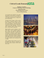
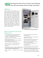
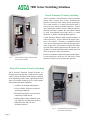
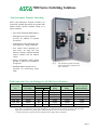
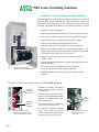
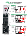
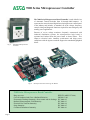
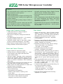
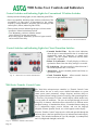
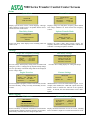
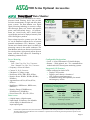
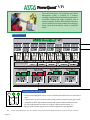
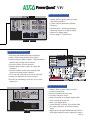
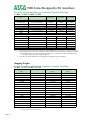
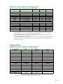
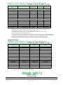
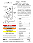
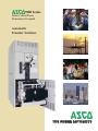
7000 Series When Critical Power Protection is Essential Automatic Transfer Switches THE POWER AUTHORITY Critical Loads Demand Healthcare Facilities Commercial Buildings/Industrial Buildings Data Processing Telecommunications Centers Process Manufacturing As we become more dependent on the quality and reliability of electrical power, interruption or complete loss of power can create serious and even crippling financial losses, or impose dangers to life and safety. Automatic Switch Company (ASCO) provides the solutions to handle the transfer of critical loads to emergency sources reliably and with state of the art products. Using ASCO products can mean the difference between a minor inconvenience and a major catastrophe. You’ll find ASCO Automatic Transfer Switches wherever there is a critical load to be protected. When flexibility in power switching is a must, ASCO offers a variety of product solutions to meet virtually every application requirement. That’s why the 7000 Series is available in the conventional, two-position transfer configuration, plus closed or delayed transition modes of operation. Additionally, switched or overlapping neutral options provide for reliable operation of ground fault protection systems and reduction of voltage transients from unbalanced load switching. ASCO automatic transfer switches are the first CE Marked, IEC 60947-6-1 compliant and Kema Keur marked Automatic Transfer Switch in the world. Page 2 The Recognized Leader in Power Transfer Switch Technology Offers the Most Advanced Automatic Transfer Switches in the World. 7000 Series ASCO Automatic Transfer Switches are the standard of the industry. High speed transfer of loads between alternate sources of power, regardless of ampacity size, is achieved by a reliable, field proven solenoid operating mechanism. When combined with a programmable microprocessor controller with keypad and LCD display, it offers the most advanced method of transferring all types of loads, such as, motors, electronic drives, UPS’s and microprocessor based systems. It is the only true double throw, inherently interlocked transfer switch in the industry and is available in ampacity sizes from 30 through 4000 amperes. 7000 Series automatic transfer switches are available open or enclosed, with the largest selection of optional accessories offered anywhere. Fig. 1 7000 Series Automatic Transfer Switch rated 3 pole 1200 amperes (shown with optional data monitor). 7000 Series Automatic Transfer Switches Product Features • Conventional two-position transfer configuration, plus closed and delayed transition modes of operation. All configurations available with either automatic or non-automatic control. • Qualified and listed to UL 1008 and CSA automatic transfer equipment standards. • Independently qualified and listed to IEC 60947-6-1, CE and Kema Keur marked (optional). • Rated up to 600 VAC, 30 through 4000 amperes. • Reliable and field proven solenoid operating • Front replaceable main and arcing contacts (600-4000 amperes). • Programmable microprocessor controller with keypad and LCD display. • Centrally located terminal block for customer control connections (260-4000 amperes). • Heavy-duty, 16mm, industrial grade control switches and indicating lights. • Switch position indicators and true source acceptability lights. mechanism. • Standard ground lug or ground bus connection. • High withstand and close-on ratings including 30 cycle • Four auxiliary contacts, two contacts closed withstand current rating for optimum flexibility in circuit breaker coordination (1000-4000 amperes). • Solid, switched, or overlapping neutral conductor options. when switch is in normal position and two contacts closed when switch is in emergency position. • Local/remote serial communications capability for interfacing with ASCO PowerQuest products. Page 3 7000 Series Switching Solutions Closed-Transition Transfer Switching ASCO Automatic Closed-Transition Transfer Switches feature main contacts that overlap, permitting the transfer of electrical loads without power interruption. The switch transfers in a make-before-break mode if both sources are within acceptable parameters. Control logic continuously monitors source conditions and automatically determines whether the load transfer should be open (conventional non-overlap mode) or closed transition. Available 150 through 4000 amperes. Closed-Transition Transfer within 5 electrical degrees is achieved passively. Active control of the engine generator is not required. Therefore, no additional control wire runs are required between the ATS and engine generator set governor. Plus, protective relaying may not be required under normal operation since the contact overlap time is less than 100 milliseconds (consult your local utility on protective relay requirements). Fig. 2 Closed-Transition Bypass Transfer Switch rated 4 pole 800 amperes. Failure to synchronize annunciation and extended parallel time protection is built-in to all 7000 Series closed transition controls to prevent abnormal operation. Delayed Transition Transfer Switching ASCO Delayed Transition Transfer Switches are designed to provide transfer of loads between power sources with an intentional load disconnect position for an adjustable period of time. Applications include older style variable frequency drives, rectifier banks, and specialized medical equipment. • Available 150 through 4000 amperes. • Utilizes reliable, field proven solenoid operating mechanisms. • Mechanical interlocks to prevent direct connection of both sources. • Indicator light (16mm, industrial grade type LED) for load disconnect position. • Adjustable time delay for load disconnect position. Fig. 3 Page 4 Delayed Transition Transfer Switch rated 4 pole 1200 amperes. 7000 Series Switching Solutions Non-Automatic Transfer Switching ASCO Non-Automatic Transfer Switches are electrically operated units which are operated with manual control switches mounted locally or at remote locations. • Sizes from 30 through 4000 amperes. • Microprocessor based controller provides for addition of optional accessories. • Controller prevents inadvertent operation under low voltage conditions. • Low control circuit operating currents allow for long line runs between remotely mounted manual control switches and the transfer switch. • Source acceptability lights inform operator if sources are available to accept load. Fig. 4 • Standard inphase monitor can be activated for transferring motor loads. Non-Automatic operated, electrically operated 400 ampere switch shown in Type 1 enclosure. Withstand and Close-On Ratings for all 7000 Series Products UL 1008 Withstand and Close-On Ratings at 480 Volts AC Switch Rating amps Current-Limiting Fuse Rating 30 70, 100, 150 150*,260, 400 600, 800 1000, 1200 1600, 2000 3000, 4000 100,000 200,000 200,000 200,000 200,000 200,000 200,000 Max. Fuse Size amps types 60 200 600 1200 2000 3000 6000 J J J L L L L Specific Breaker Rating “Any” Breaker Rating 30 Cycles Long Time Withstand Ratings 10,000 22,000 42,000 65,000 85,000 100,000 100,000 10,000 10,000 35,000 50,000 85,000 100,000 100,000 N/A N/A N/A N/A 65,000 65,000 65,000 Notes: All values are available symmetrical RMS amperes and tested in accordance with the withstand and close-on requirements of UL 1008. See publication 1128 for more information on withstand and close-on ratings for ASCO transfer switches. Application requirements may permit higher withstand ratings for certain size switches (Contact ASCO). * 150 amp 7000 Series in bypass-isolation configurations have higher WCR as indicated. Page 5 7000 Series Switching Solutions Automatic Transfer Bypass-Isolation Switching ASCO Automatic Transfer & Bypass-Isolation Switches are available in open transition, closed transition and delayed transition designs. The bypass and isolation features allow power transfer switches to be inspected, tested, and maintained without any interruption of power to the load. • Available 150 to 4000 amperes. • Bypass switch and transfer switch have identical electrical ratings. • Heavy duty mechanical interlocks prevent undesirable operation. • Bypass contacts carry current only during bypass mode. • Allows bypass-isolation without load interruption. • Transfer switch is drawout design for ease of maintenance. • Bypass and isolation handles are permanently mounted. The bypass switch has dead front quick-make, quick-break operation for transferring of loads between live sources. • Bypass switch is fully rated for use as a manual 3-position transfer switch. • Bypass and isolation functions are simple, requiring a total of two operating handles. Fig. 5 Bypass-Isolation Transfer Switch rated 4 pole 2000 Amperes. • No toggle switches, push buttons, selector switches or levers are required for bypass-isolation operation. • Mechanical flag indicators show bypass and transfer switch positions. Transfer Switch Drawout Features (1000-2000 amperes) • Automatic Automatic Secondary Disconnects Automatic Shutters (optional) secondary disconnects remove all control power as switch is withdrawn. • Drawout carriage provides for easy transfer switch maintenance and/or removal via commercially available breaker hoists. Self Aligning Jaws • For optional transfer switch lifting yoke, specify accessory 82B. • For Fig. 6 Page 6 Bypass-Isolation Transfer Switch secondary disconnects and optional automatic shutters. optional automatic shutters which close when the transfer switch is withdrawn to provide bus isolation, specify accessory 82C. Fig. 7 Bypass-Isolation Transfer Switch Self Aligning power Jaws. 7000 Series Switching Solutions Bypass and Isolation Handles - Simple as 1, 2, 3 Manual engine start switch Bypass to Normal Push in bypass handle and turn it clockwise Bypass Switch E ï Source availability and “not in automatic” mode indicators Bypass Handle L Isolation Handle 1 Bypass Handle (Quick-MakeQuick-Break) N Automatic Transfer Switch Mechanical bypass switch position flags Test Position Bypass Switch Turn isolation handle counter clockwise until window shows “Test” à Isolation Handle E L ï 2 N Automatic Transfer Switch Mechanical isolation handle position window (connected/ test/isolate) Isolation Position Turn isolation handle counter clockwise until window shows “Isolate” Bypass Switch à Fig. 8 Bypass-Isolation Switch user interface (1000-2000 amperes shown). Isolation Handle Padlocking provisions 3 L ï Isolation Handle E N Automatic Transfer Switch Page 7 7000 Series Microprocessor Controller The 7000 Series Microprocessor Based Controller is used with all sizes of Automatic Transfer Switches from 30 through 4000 amperes. It represents the most advanced digital based microprocessor control panel in the industry and includes, as standard, all of the voltage, frequency, control, timing and diagnostic functions required for most emergency and standby power applications. Because of severe voltage transients frequently encountered with industrial distribution systems, the microprocessor logic board is separated and isolated from the power board as shown below. This improves electrical noise immunity performance and helps assure compliance with the rigorous transient suppression standards highlighted below. Fig. 9 7000 Series Microprocessor Controller. Fig.10 Microprocessor Power and Logic PC Boards. 7000 Series Microprocessor Based Controller Ring wave test. Class B Conducted and Class A Radiated Emission. Electrostatic Discharge Immunity, direct contact and air discharge. Radiated Electromagnetic Field Immunity. Electrical Fast Transient Immunity. Surge Immunity. Conducted Disturbance Immunity. Page 8 IEEE472 (ANSI C37.90A) EN55011 1991 IEC1000-4-2 IEC1000-4-3 IEC1000-4-4 IEC1000-4-5 IEC1000-4-6 7000 Series Microprocessor Controller Features • The same controller can be used for open, closed and • Selectable multi-language display (English, German, delayed transition control sequences. Digital microprocessor. Touch pad programming of features and settings without the need for meters, variable power supplies and reference manuals. Sixteen (16) selectable operating voltages available in a single Controller. On-board diagnostics provide control panel and ATS status information to analyze system performance. Displays and counts down active timing functions. Spanish, French. For others contact ASCO). Password protection to prevent unauthorized tampering. Serial communications board (RS-422/485 protocol) for viewing adjustments and features with ASCO PowerQuest communications products. Specify optional accessory 72A. • • • • • • • • Programmable load shed option for SYNCHROPOWER® bus optimization applications. Specify optional accessory 30B. Voltage and Frequency Sensing Time Delays • 3-Phase under and over voltage settings on • • • • • • normal and emergency sources. Under and over frequency settings on normal and emergency. True RMS Voltage Sensing with +/- 1% accuracy; Frequency Sensing Accuracy is +/- 0.2%. Selectable settings: single or three phase voltage sensing on normal and emergency; 50 or 60Hz. Phase sequence sensing for phase sensitive loads. Voltage unbalance detection between phases. Status and Control Features • Output contacts for engine-start signals. • Selection between “commit/no-commit” on • • • • transfer to emergency after engine start and normal restores before transfer. Advanced inphase algorithm which automatically measures the frequency difference between the two sources and initiates transfer at appropriate phase angles to minimize disturbances from transferring motor loads. Event log displays 99 logged events with the time and date of the event, event type and event reason. Output signals for remote indication of normal and emergency source acceptability Statistical ATS/System monitoring data screens which provide: • Total number of ATS transfers. • Number of ATS transfers caused by power source failure. • Total number of days ATS has been in operation. • Total number of hours that the normal and emergency sources have been available. • • • • • • • • Engine start time delay - delays all engine starting signals to override momentary normal source outages - adjustable 0 to 6 seconds (can be extended to 60 minutes with external 24 volt DC source). Transfer to emergency time delay - adjustable 0 to 60 minutes. Emergency source failure time delay to ignore momentary transients during initial generator set loading - adjustable 0 to 6 seconds. Retransfer to normal time delay with two settings: • Power failure mode - 0 to 60 minutes. • Test mode - 0 to 60 minutes. Unloaded running time delay for engine cooldown - adjustable 0 to 60 minutes. Pre and post transfer signal time delay for selective load disconnect with a programmable bypass on source failures - adjustable 0 to 5 minutes. This signal can be used to drive a customer furnished relay, or for (2) sets of double throw contacts rated 3 amps at 480 volts AC, specify ASCO optional accessory 31Z. Fully programmable engine exerciser with (7) seven independent routines to exercise the engine generator, with or without loads, on a daily, weekly, bi-weekly or monthly basis. Contains all alarm signals, logic and time delays for use with closed transition switches. • Insynch time delay - 0 to 3 seconds. • Failure to synchronize - 1 to 5 minutes. • Extended parallel - 0.1 to 1.0 seconds. Delayed transition load disconnect time delay adjustable 0 to 5 minutes. Page 9 7000 Series User Controls and Indicators Control Switches and Indicating Lights for Conventional 2-Position Switches • Switch position indicating lights (16 mm, industrial grade LEDs). • Source acceptability indicating lights with true indication of the acceptability of each source, as determined by the voltage, frequency, voltage unbalance, and phase sequence settings of the control panel (16mm, industrial grade LEDs). • Three position (16mm, industrial grade type) selector switch: • Automatic: Normal maintained position. • Test: Momentary position to simulate normal source failure for system test function. • Reset Delay Bypass: Momentary position to bypass transfer and re-transfer time delay. Fig. 11 7000 Series User Controls and Indicators. Control Switches and Indicating Lights for Closed Transition Switches • • • • Fig. 12 7000 Series User Controls and Indicators. • Extended Parallel Time - Provides visual indication when the pre-set extended parallel time is exceeded and automatically opens the emergency or normal main contacts. The ATS remains locked out until the alarm reset switch is operated. Failure To Synchronize - Visually displays a failure to synchronize alarm if the time delay settings is exceeded. TS Locked Out - Prevents transfer in either direction if the extended parallel time is exceeded. Alarm Reset - Resets extended parallel and failure to synchronize alarms. Closed Transition Bypass - Allows transfer between sources in an open transition mode. 7000 Series Transfer Control Center The 7000 Series microprocessor controller is a Transfer Control Center which allows the user to easily access detailed information on: system status; power source parameters; voltage, frequency and time delay settings; optional feature settings; historical event log; and system diagnostics. A four line, (20) character LCD has a backlit display which enables easy viewing under all conditions. The user can navigate through all screens using only six buttons, which also allows selection of: 18 different source parameter settings; 16 standard time delays; 12 standard feature settings; up to (7) independent engine exercise routines; and even the language (English, German, Spanish, French, etc.) which appears on the display. Since the Transfer Control Center must be visible and operable through the enclosure door, it has been qualified for use in industrial and outdoor applications. This includes installation in Type 3R (raintight), 4 (weatherproof) and 12 (oiltight and dusttight) enclosures. Fig. 13 Page 10 7000 Series Transfer Control Center. 7000 Series Transfer Control Center Screens Status System Status Normal OK Load on Normal Displays system status in clear, concise language. Message shown indicates normal source is acceptable and the load is connected to the normal source. Time Delay Status Source Status Normal Source Vab=480V....................ABC Vbc=480V.........Vunbal=1% Vca=480V................60.0Hz Displays voltage for each phase, frequency, phase rotation and voltage unbalance for both normal and emergency sources. Inphase Transfer Mode Normal OK Emerg OK TD.Engine.Cooldown: 4min15s Waiting for In-Sync -45o 0.02HZ Vdf=1.1% Active time delay status displays time remaining until next control event. Displays the relative phase angle between sources, the frequency difference and voltage differential to indicate the controller is awaiting an inphase condition. Settings Voltage and Frequency Settings Time Delay Settings Normal Voltage Dropout.............75%.360V Pickup...............90%.432V O.V. Trip.........110%.582V TD N>E Xfer Signal Bypass if N Fail: No Pre Xfer: 0 min 20S Post Xfer: 0 min 20S Provides voltage and frequency setting values for normal and emergency sources. Voltage pick-up, dropout and trip settings are set in percentage of nominal voltage and are also displayed in rms voltage values. Provides direct reading display for setting time delays. Engine Exerciser Feature Settings P1..................Engine.Exerciser Enable:.....Yes....WLoad:....Yes Start:19h30. ALL MON Run.Time:...............2h15min Shed Load Seven independent programs, load/no load selection, flexible run times and daily, weekly, bi-weekly and monthly exercise routines. Direction: Inphase: No From E TD/0.25 Standard features can be activated with the keypad. As an example, when enabled, the “shed load” option causes the transfer switch to transfer the load off of the specified source. If desired, the load shed transfer can be made inphase. Data Logging ATS Statistics ATS Statistics ATS Total Xfers: 46 SRC Fail Tot Xfers: 20 Days Energized: 36.5 Instant availability of statistical information on total number of ATS transfers, number of transfers caused by power failures and total days controller has been energized, plus more. Historical Event Log 16.AUG02/95..........13h10:17 Eng.Start...............NormFail. 15.AUG02/95...........13h10:25 Xfer.N>E................................ Displays detailed information for last 99 events, including time of occurance, length of event, date and reason for event. Page 11 7000 Series Optional Accessories Time Delays Neutral Conductor Options 2C An extended time delay on engine starting. Adjustable from 0 to 60 min in 1 second steps. Factory set at 5 minutes. • Note: 7000 Series controller provides a similar standard time delay which can be extended to 60 minutes with an external 24 volt DC source. • • Solid neutral, with fully-rated terminals. (AL-CU) UL Listed. Conventional neutral switching pole. Overlapping neutral transfer contacts. Allows for proper ground-fault sensing and avoids generator voltage transients during transfer. Manual Controls for Automatic Transfer Switches Notes: Specify neutral option in catalog number, see page 16 for instructions. 6C Reset switch for manual retransfer to normal with automatic retransfer in the event of emergency source failure. 6D Selector switch for automatic/manual retransfer to normal. Automatic bypass if emergency fails. Extension Harness Engine Generator Controls and Accessories 23B Three phase ammeter with selector switch (with current transformers and shorting blocks). 24B Three phase voltmeter with selector switch. 12 Three position engine control selector switch. Positions: 1 - Stop 2 - Automatic 3 - Engine Test Note: Engine controls containing “engine stop” positions should be located at the engine generator. (Consult ASCO for application assistance). Indicators 14A/14B Additional auxiliary contact sets to indicate switch position. Two sets are standard. Specify total number of sets if more are required. 18B Two-pole, double-throw contacts operate when emergency source voltage is present at transfer switch terminals. 18G Two-pole, double-throw contacts operate when normal source voltage is present at transfer switch terminals. 99 “Push-to-Test” feature on all pilot light indicators. Customer Control Circuits 30A Load-shedding circuit initiated by opening of a customer-supplied contact. 30B Load-shedding circuit initiated by removal of customer-supplied control voltage. (Specify voltage). 31Z Selective load disconnect control contacts (two provided) which operate with time delay prior to and/or after load transfer and retransfer. 43R Terminal block for all customer control connections on 30-150 amp only (standard on all other sizes). Notes: Page 12 37B Six foot (6’) extension harness to increase distance between transfer switch and control panel on open-type units. Analog Load Metering Options Notes: Refer to ASCO 7000 Series Data Monitor on page 13 which provides voltage, frequency and power monitoring. Serial Communications 72A Serial communication module for remote communications to ASCO PowerQuest products. Surge Protection - ASCO Pulsar 450 rated 40KA 73AC1 Normal source protection. (3∅, 4wire WYE) 73AC2 Emergency source protection. (3∅, 4wire WYE) 73AC3 Load side protection. (3∅, 4wire WYE) Notes: Other distribution voltages available (Contact ASCO). Bypass Isolation Switch Options 14A1 Auxiliary contact to close in “Bypass to Normal” position. 14B1 Auxiliary contact to close in “Bypass to Emergency” position. 14T Auxiliary contact to close when transfer switch is in “Automatic” position. 14U Auxiliary contact to close when transfer switch is in “Isolate” position. 14V Auxiliary; contact to close when transfer switch is in “Test” position. ATS Bypass Isolation Drawout Features (1000-2000 amperes) 82B Transfer switch lifting yoke to facilitate the removal of the transfer switch from the drawout carriage. 82C Automatic shutters to provide isolation of bus stabs. An externally operable quick-make, quick-break (QMQB), manual handle is available on some 7000 Series product configurations. (Consult ASCO for guidance). 7000 Series Optional Accessories Data Monitor The ASCO PowerQuest Data Monitor is a microprocessor based metering device that provides real-time measurements of single and three phase power systems. The Data Monitor uses digital signal processing technology to measure voltage and current per phase; real, reactive and apparent power, and bi-directional energy. All measurements are viewed locally with a backlit liquid crystal display and can be displayed remotely with ASCO PowerQuest products. Direct voltage input for systems up to 600 Volts AC can be monitored without the use of external potential transformers (PTs). Measures 3 phase currents and a fourth current input is available for measuring current in the neutral conductor. The Data Monitor includes one discrete input for transfer switch position, eight general purpose discrete inputs, and four relay outputs for controlling or monitoring external devices. POWER SYSTEM TOTAL 404 KW +1.00 PF 0 KVAR 60.00 Hz 404 KVA ATSºn NORM Fig. 14 ASCO Data Monitor. Power Metering Configurable Designations • Voltage: • Local - A 4 line 20 character LCD backlit display. • Remote - With optional Acc. 72A communication • • • • • • • • • Line - Line: VAB, VBC, VCA, VAVERAGE Line - Neutral: VAN, VBN, VCN, VAVERAGE Frequency: 45.0 to 66.0 Hertz Current: IA, IB, IC, IAVERAGE Unbalance %: Voltage, Amps Real Power: KWA, KWB, KWC, KWNET Reactive Power: KVARA, KVARB, KVARC, KVARNET Apparent Power: KVAA, KVAB, KVAC, KVANET Real Energy: KWHIMPORT, KWHEXPORT, KWHNET Reactive Energy: KVARHIMPORT, KVARHEXPORT, KVARHNET Power Factor: PFA, PFB, PFC, PFNET Data Access module and ASCO PowerQuest monitoring systems. Integrated ATS Features • When configured on load of ATS: • Displays ATS position. • Displays power data as a function of • Optional Configurations and Connection Arrangements Connected To: Load Normal Emergency • 8 digital inputs, 4 digital outputs. • Input/Output 15-character, user definable screen display for identification of input/output signals. Note: ATS position (normal/emergency). Accumulates energy data separately for normal and emergency sources. With Display Acc. 85L Acc. 85N Acc. 85M Without Display Acc. 75L Acc. 75N Acc. 75M Add suffix “A” to above designations if neutral conductor monitoring is required. Note: Accessory 75 and 85 includes component mounting, CTs, shorting blocks and all necessary interwiring. Consult ASCO publications 3014, 3016 and 3047 for specifications and ordering information on ASCO PowerQuest products. The ASCO PowerQuest Data Monitor is also available as a separate unit for monitoring electrical parameters anywhere in the power distribution system. Page 13 VPi The ASCO PowerQuest VPi monitoring and control management system is available in a windows operating system that allows the monitoring and control of transfer switches and engine generators from a personal computer. With an ASCO modem connection, you can remotely access and/or control your emergency power system, from around the corner or around the world. Summary Screen Convenient One-Line Diagram L E E Note: Page 14 N N • Colored icons highlighted to show source availability and which source is connected to load. • Contacts move on icon to indicate main contact position of transfer and bypass switch. (Automatic transfer and automatic transfer and bypass isolation switches must be provided with optional accessory 14 auxiliary contacts shown on page 12.) • Bypass switch contacts appear on icon when configured by user input data. Consult ASCO publications 3014, 3016 and 3047 for specifications and ordering information on ASCO PowerQuest products. VPi Data Monitor Detail Screen • Voltage: phase to phase; phase to neutral and voltage unbalance. • 3 phase currents and neutral (optional). • Frequency. • Kilowatt hours - normal and emergency. • Status and control of (4) digital outputs. • Status of (8) digital inputs. • Device ratings: CT and PT ratio. Transfer Switch Detail Screen • ATS rating and identification data is displayed. • Allows remote testing and time delay bypass. • Voltage, frequency, phase sequence, voltage unbalance and time delay settings can be checked. • Viewing of engine exercise schedules. • Displays phase to phase voltage on normal and emergency. • Provides complete system status message from 7000 series microprocessor controller. • View event log on the last 99 events for each ATS. • Arrange test schedules for transfer switches. • Provides for monitoring of local site or up to 1000 remote sites. Engine-Generator Details • Voltage: Phase to phase; Phase to neutral • Current for each phase. • Kilowatts and kilowatt hours total. • Frequency and power factor. • Status and control of (4) digital outputs which can be customized by the user. • Status of (8) digital inputs. • “Alarm Enabled” selection. These alarms flash the “engine-generator” icon on the summary screen. • Digital inputs for engine malfunctions are derived from engine mounted sensors (supplied by others). Page 15 7000 Series Ordering Information To order an ASCO 7000 Series Automatic Transfer Switch, complete the following catalog number: 7 TS A Product A Automatic NonAutomatic N TS Conventional 2-Position TB Open Transition Bypass CTS Closed Transition CTB Closed Transition Bypass DTS Delayed Transition DTB Delayed Transition Bypass A + Neutral Code --- No Neutral A Solid Neutral B C 3 + + Phase Poles 2 3 Switched Neutral Overlapping Neutral 400 Amperes 30 70 100 150 260 400 600 800 N + 5X + C Voltage Code Grp Code Cabinet + 1000 1200 1600 2000 3000 4000 A B C D E F G H J K L M N P Q R 115 120 208 220 230 240 277 380 400 415 440 460 480 550 575 600 5 5X --C D E F G H No Cabinet K L Type 7 enclosure Type 1 enclosure Type 1 gasketed Type 2 enclosure Type 3R enclosure Type 4 enclosure Type 4X enclosure (stainless steel) Type 12 enclosure Note: Switches rated 30-150, 600-2000 amps available with 2, 3 or either switched neutral (4 poles) or overlapping neutral (optional). For 4 pole applications on switches rated 260 to 400 amps and 3000 to 4000 amps specify overlapping switched neutral (optional). Overlapping neutral is not available on delayed transition transfer products. The Example Catalog Number above is 7ATSA3400N5XC (X could be for Accessory 85L ASCO Data Monitor connected to load). 7A TS, 7N TS, 7A DTS, 7A CTS, 7N DTS, 7N CTS 7A TB, 7N TB, 7A DTB, 7A CTB, 7N DTB, 7N CTB Sizes of UL-Listed Solderless Screw-Type Terminals for External Power Connections Sizes of UL-Listed Solderless Screw-Type Terminal for External Power Connections Switch Rating Max # of Conductors amps per Terminal One 30, 70, 100 150 One 240-400 One Two Three Four 600-800 1000-1200 1 1600-2000 3000-40002 Range of AL-CU Conductor Sizes # 14 to 2/0 AWG #8 to 3/0 AWG #4 AWG to 600 MCM #1/0 AWG to 250 MCM #2 AWG to 600 MCM #1/0 AWG to 750 MCM Six #1/0 AWG to 750 MCM Suitable for Bus Bar Connection Notes: 1. Unit is designed for top cable entry of emergency and load and bottom entry of normal. Optionally, the switch may be supplied with reverse source and/or bottom entry load. A cable pull box is also available for all top or bottom cable access (optional). 2. All main terminals are rear connected. 3000 and 4000 amp switches are arranged for bus bar connection. Contact ASCO if provisions for cable connection are required. Page 16 Switch Rating Max # of Conductors amps per Terminal One 150,260,400 Two Three 600-800 1000-12001 1600-20001 30001 40001 Notes: # 4 AWG to 600 MCM # 1/0 AWG to 250 MCM # 2 AWG to 600 MCM Four # 1/0 AWG to 750 MCM Six Eight # 1/0 AWG to 750 MCM Twelve 1. Range of AL-CU Conductor Sizes # 2 AWG to 600 MCM # 2 AWG to 600 MCM All main terminals are rear connected. 7000 Series Designed to Fit Anywhere Automatic 2-Position Transfer Switching 7A TS, 7N TS Switch Rating amps Enclosed UL Type 1 30, 70, 100, 150 260, 400 600, 800 1000, 12001 1600, 20002 30002 40002 Open Configuration 30, 70, 100, 150 260, 400 260, 400 600, 800 600, 800 1000, 1200 1600, 2000 3000 4000 Poles Width inches (mm) Height inches (mm) Depth inches (mm) 2, 3 or 3 with neutral B/C 2, 3, or 3 with neutral C 2, 3 or 3 with neutral B/C 2, 3 or 3 with neutral B/C 2, 3 or 3 with neutral B/C 2, 3, or 3 with neutral C 2, 3, or 3 with neutral C 18 (457) 22 (559) 30 (762) 38 (965) 38 (965) 37 (940) 46 (1168) 48 (1219) 48 (1219) 63(1600) 87 (2210) 91 (2311) 91 (2311) 91 (2311) 13 (330) 13 (330) 17½ (445) 23 (584) 48 (1219) 60 (1524) 72 (1829) 2, 3 or 3 with neutral B/C 2 or 3 2, 3, or 3 with neutral C 2 or 3 3 with neutral B/C 2, 3 or 3 with neutral B/C 2, 3 or 3 with neutral B/C 2, 3, or 3 with neutral C 2, 3, or 3 with neutral C 10¼ (260) 12 (305) 14½ (368) 19¼ (489) 22¾ (578) 33¼ (845) 33¼ (845) 31½ (800) 41 (1041) 10¼ (260) 18½ (470) 18½ (470) 25 (635) 25 (635) 43 (1092) 28 (711) 52 (1321) 52 (1321) 5½ (140) 6-7/8 (175) 6-7/8 (175) 11 (279) 11 (279) 22¼ (565) 33½ (842) 22½ (572) 25½ (648) Notes: 1. Unit is designed for top cable entry of emergency and load and bottom entry of normal. Optionally, the switch may be supplied with reverse source and/or bottom entry load. A cable pull box is also available for all top or all bottom cable access when required (optional). 2. Enclosures for 1600 - 4000 amp are free-standing with removable top, sides, and back. Shipping Weights 2-Position Transfer Switching 7A TS, 7N TS Switch Rating amps 30, 70, 100 30, 70, 100 30, 70, 100 150 150 150 260, 400 260, 400 260, 400 600, 800 600, 800 600, 800 1000, 1200 1000, 1200 1000, 1200 1600, 2000 1600, 2000 1600, 2000 3000 3000 3000 4000 4000 4000 Notes: Poles 2 3 3 with B/C 2 3 3 with B/C 2 3 3 with C 2 3 3 with B/C 2 3 3 with B/C 2 3 3 with B/C 2 3 3 with C 2 3 3 with C Enclosed lb (kg) 67 (31) 70 (32) 73 (33) 69 (32) 72 (33) 75 (34) 117 (53) 125 (57) 133 (61) 250 (114) 260 (118) 320 (145) 870 (395) 920 (417) 970 (440) 1110 (503) 1160 (525) 1210 (548) 1983 (900) 2133 (968) 2233 (1013) 2208 (1002) 2433 (1104) 2533 (1149) Open* lb (kg) 15 (7) 18 (8) 21 (10) 17 (8) 20 (9) 23 (11) 37 (17) 45 (21) 53 (24) 135 (62) 145 (66) 155 (71) 335 (152) 385 (174) 435 (197) 370 (167) 420 (190) 470 (213) 750 (340) 900 (409) 1000 (454) 975 (443) 1200 (545) 1300 (590) * Open widths include transfer switch and control panel. 1600-4000 amp enclosures require ventilation openings, refer to drawings for details. Page 17 7000 Series Designed to Fit Anywhere Closed Transition and Delayed Transition Transfer Switching 7A DTS, 7A CTS, 7N DTS, 7N CTS Switch Rating amps Poles Width inches (mm) Height inches (mm) Depth inches (mm) 150, 260, 4001 600, 800 1000, 12002 1600, 20003 30003 40003 2, 3 or 3 with neutral C 2, 3 or 3 with neutral B/C 2, 3 or 3 with neutral B 2, 3 or 3 with neutral B 2, 3 or 3 with neutral C 2, 3 or 3 with neutral C 24 (610) 30 (762) 38 (965) 38 (965) 37 (940) 46 (1168) 63 (1600) 63 (1600) 87 (2210) 91 (2311) 91 (2311) 91 (2311) 17½ (445) 17½ (445) 23 (584) 48 (1219) 60 (1524) 72 (1829) Open Configuration 150, 260, 400 600, 800 600, 800 1000, 1200 1600, 2000 3000 4000 2, 3 or 3 with neutral C 2 or 3 with neutral B/C 2 or 3 with neutral B/C 3 or 3 with neutral B 2, 3 or 3 with neutral B 2, 3 or 3 with neutral C 2, 3 or 3 with neutral C 14 ¾ (375) 19¼ (489) 22¾ (578) 33¼ (845) 33¼ (845) 31½ (800) 41 (1041) 30 (762) 28¾ (730) 28¾ (730) 43 (1092) 28 (711) 52 (1321) 52 (1321) 5 7/8 (149) 11 (279) 11 (279) 22¼ (565) 29 (737) 26½ (637) 29½ (749) Enclosed UL Type 1 Notes:1. For 400 amp, 7A DTS and 7N DTS with neutral code B; dimensions are 30 (762) X 63 (1600) x 1742 (445). 2. Unit is designed for top cable entry of emergency and load and bottom entry of normal. Optionally, the switch may be supplied with reverse source and/or bottom entry load. A cable pull box is also available for all top or all bottom cable access when required (optional). 3. Enclosures for 1600 - 4000 amp are free-standing with removable top, sides, and back. Shipping Weights Closed Transition and Delayed Transition Transfer Switching 7A DTS, 7A CTS, 7N DTS, 7N CTS Switch Rating amps 150, 260, 400 150, 260, 400 150,260, 400 600, 800 600, 800 600, 800 1000, 1200 1000, 1200 1000, 1200 1600, 2000 1600, 2000 1600, 2000 3000 3000 3000 4000 4000 4000 Notes: Page 18 Poles 2 3 3 with C 2 3 3 with B/C 2 3 3 with B 2 3 3 with B 2 3 3 with C 2 3 3 with C Enclosed lb (kg) 137 (62) 145 (66) 153 (69) 260 (118) 270 (122) 330 (150) 1005 (456) 1055 (478) 1105 (501) 1300 (590) 1350 (612) 1400 (635) 2000 (908) 2150 (976) 2230 (1012) 2360 (1071) 2580 (1171) 2680 (1217) Open* lb (kg) 45 (21) 53 (24) 63 (28) 145 (66) 155 (71) 165 (75) 470 (213) 520 (236) 570 (258) 505 (229) 555 (252) 605 (274) 767 (348) 917 (416) 997 (452) 1127 (511) 1347 (611) 1447 (657) * Open widths include transfer switch and control panel. 1600-4000 amp enclosures require ventilation openings, refer to drawings for details. Automatic Transfer Bypass-Isolation Switching with Transfer Switch Engaged 7A TB, 7N TB Switch Rating amps Poles Width inches (mm) Height inches (mm) Enclosed UL Type 1 150, 260, 4001 600, 8002 1000, 12003 1600, 20003 30004 40004 2, 3 or 3 with neutral C 2, 3 or 3 with neutral B/C 2, 3 or 3 with neutral B/C 2, 3 or 3 with neutral B/C 2, 3 or 3 with neutral C 2, 3 or 3 with neutral C 28½ (724) 36 (914) 38 (965) 38 (965) 78 (1981) 96½ (2451) 62 (1575) 90 (2286) 91 (2311) 91 (2311) 91 (2311) 91 (2311) 19 (483) 22 (559) 60 (1524) 60 (1524) 72 (1829) 72 (1829) Open Configuration 150, 260, 4001 150, 260, 4001 600, 8002 600, 8002 1000, 12003 1600, 20003 2 or 3 3 with neutral C 2 or 3 2, 3 or 3 with neutral B/C 2, 3 or 3 with neutral B/C 2, 3 or 3 with neutral B/C 14 ¾ (375) 19¾ (500) 23¾ (603) 27¼ (692) 38 (965) 38 (965) 61½ (1553) 61½ (1553) 67¼ (1708) 67¼ (1708) 72 (1829) 72 (1829) 22¼ (565) 22¼ (565) 24¾ (629) 24¾ (629) 38 (965) 38 (965) Notes: Depth inches (mm) 1. Handles extend 3½ inches (89mm). 2. Handles extend 6¼ inches (159mm) standard enclosures for 600 - 800 amp sizes are suitable for top cable entrance only. Specify 44” wide enclosure for bottom cable entry. 3. Recommended clearance to enclosure: 3 feet (914mm) from rear, 4 feet (1219mm) from front (25 inches required for transfer switch drawout). 4. For 3000 - 4000 amp sizes, ATS and bypass sections can be reversed, contact ASCO. Recommended clearance to enclosure: 3 feet (914mm) from rear, 5 feet (1524mm) from front (3 feet required for transfer switch rollout). Shipping Weights Automatic Transfer Bypass-Isolation Switching with Transfer Switch Engaged 7A TB, 7N TB Switch Rating amps 150, 260, 400 150, 260, 400 150, 260, 400 600, 800 600, 800 600, 800 1000, 1200 1000, 1200 1000, 1200 1600, 2000 1600, 2000 1600, 2000 3000 3000 4000 4000 Notes: Poles 2 3 3 with C 2 3 3 with B/C 2 3 3 with B/C 2 3 3 with B/C 3 3 with C 3 3 with C Enclosed lb (kg) Open* lb (kg) 340 (154) 350 (158) 360 (163) 695 (315) 710 (322) 725(329) 1910 (866) 2130 (966) 2350 (1066) 2180 (989) 2360 (1070) 2540 (1152) 5100 (2314) 5500 (2495) 6300 (2858) 6900 (3130) 135 (61) 145 (66) 155 (70) 370 (168) 385 (175) 425 (193) 1280 (507) 1280 (580) 1440 (652) 1300 (589) 1550 (702) 1800 (815) ------------- * Open widths include transfer switch, bypass-isolation switch and control panel. 1000-4000 amp enclosures require ventilation openings, refer to drawings for details. Page 19 Automatic Transfer Bypass-Isolation in Closed Transition and Delayed Transition Switching. 7A DTB, 7A CTB, 7N DTB, 7N CTB Switch Rating amps Poles Width inches (mm) Height inches (mm) Enclosed UL Type 1 150, 260, 4001,5 600, 8002 1000, 12003 1600, 20003 30004 40004 2, 3 or 3 with neutral C 2, 3 or 3 with neutral B/C 2, 3 or 3 with neutral B/C 2, 3 or 3 with neutral B/C 2, 3 or 3 with neutral C 2, 3 or 3 with neutral C 28½ (724) 36 (914) 38 (965) 38 (965) 78 (1981) 96½ (2451) 74 (1880) 90 (2286) 91 (2311) 91 (2311) 91 (2311) 91 (2311) 19 (483) 22 (559) 60 (1524) 60 (1524) 72 (1829) 72 (1829) Open Configuration 150, 260, 4001,5 150, 260, 4001,5 600, 8002 600, 8002 1000, 12003 1600, 20003 2 or 3 3 with neutral C 2 or 3 2, 3 or 3 with neutral B/C 2, 3 or 3 with neutral B/C 2, 3 or 3 with neutral B/C 14 ¾ (375) 19¾ (500) 23¾ (603) 27¼ (692) 38 (965) 38 (965) 61½ (1553) 61½ (1553) 67¼ (1708) 67¼ (1708) 72 (1829) 72 (1829) 22¼ (565) 22¼ (565) 24¾ (629) 24¾ (629) 38 (965) 38 (965) Notes: Depth inches (mm) 1. Handles extend 3½ inches (89mm). 2. Handles extend 6¼ inches (159mm) standard enclosures for 600 - 800 amp sizes are suitable for top cable entrance only. Specify 44” wide enclosure for bottom cable entry. 3. Recommended clearance to enclosure: 3 feet (914mm) from rear, 4 feet (1219mm) from front (25 inches required for transfer switch drawout). 4. For 3000 - 4000 amp sizes, ATS and bypass sections can be reversed, contact ASCO. Recommended clearance to enclosure: 3 feet (914mm) from rear, 5 feet (1524mm) from front (3 feet required for transfer switch rollout). 5. 400 amp, 7A DTB and 7N DTB with neutral code B are 36 (914)W x 90 (2286)H x 22 (559)D. 6. Overlapping neutral (code C) not available on 7A DTB and 7N DTB switching arrangements. Shipping Weights Automatic Transfer Bypass-Isolation in Closed Transition and Delayed Transition Switching. 7A DTB, 7A CTB, 7N DTB, 7N CTB Switch Rating amps 150, 260, 400 150, 260, 400 150, 260, 400 600, 800 600, 800 600, 800 1000, 1200 1000, 1200 1000, 1200 1600, 2000 1600, 2000 1600, 2000 3000 3000 4000 4000 Notes: Poles 2 3 3 with C 2 3 3 with B/C 2 3 3 with B 2 3 3 with B 3 3 with C 3 3 with C Enclosed lb (kg) Open* lb (kg) 340 (154) 350 (158) 360 (163) 695 (315) 710 (322) 750 (340) 2045 (928) 2265 (1027) 2485 (1127) 2315 (1050) 2495 (1132) 2675 (1213) 5100 (2314) 5500 (2495) 6300 (2858) 6900 (3130) 145 (66) 155 (70) 165 (75) 385 (175) 400 (181) 440 (200) 1225 (556) 1415 (642) 1575 (714) 1435 (651) 1685 (764) 1935 (878) ------------- * Open widths include transfer switch, bypass-isolation switch and control panel. 1000-4000 amp enclosures require ventilation openings, refer to drawings for details. 800-937-ASCO www.asco.com ASIA • AUSTRALIA • BRAZIL • CANADA • GERMANY • JAPAN • MEXICO • SOUTH AFRICA • UNITED ARAB EMIRATES • UNITED KINGDOM • UNITED STATES Florham Park, New Jersey 07932 USA Publication 3040 © Automatic Switch Co. 1998 Printed in the U.S.A.