1
Application
This manual has been issued by Canon Inc. for qualified persons to learn technical theory, and
repair of the products.
Corrections
This manual could include typographical errors or technical inaccuracies due to improvements or
changes in the products. When changes occur in applicable products or in the content of this manual,
Canon will release service manual report as the need arises. In the event of major changes in the
contents of this manual over a long or short period, Canon may issue new editions of this manual.
The following paragraph does not apply to any countries where such provisions are inconsistent
with local law.
Trademarks
The product names and company names described in this manual are the registered trademarks of
the individual companies.
Copyright
This manual is copyrighted with all rights reserved. Under the copyright laws, this manual may not
be copied, reproduced, published (including on the World Wide Web) or translated into another
language, in whole or in part, without the written consent of Canon Inc..
Copyright © 2002 by Canon Inc.
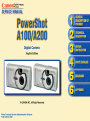
CANON INC.
Digital Imaging Products Service Dept.
30-2, Shimomaruko 3-Chome, Ohta-ku,
Tokyo 146-8501, Japan
SAFETY PRECAUTIONS
The following precautions should be observed when servicing.
1.
Since many parts in the unit have special safety-related characteristics, always use genuine CANON replacement parts.
Especially critical parts in the power circuit block should not be replaced with other makes.
2.
Critical parts are marked with ! in the schematic diagrams.
When servicing, observe the original lead dress. If a short circuit is found, replace all parts which have been overheated or damaged
3.
by the short circuit.
After servicing, see to it that all the protective devices such as insulation barriers, insulation papers shields are properly installed.
4.
After servicing, make the following leakage current checks to prevent the customer from being exposed to shock hazards.
4-1 Leakage Current Cold Check
1) Unplug the AC cord and connect a jumper between the two prongs on the plug.
2) Measure the resistance value, with an ohmmeter, between the jumpered AC plug and each exposed metallic cabinet part
on the equipment such as screwheads, connectors, control shafts, etc. When the exposed metallic part has a return path to
the chassis, the reading should be between 1MΩ and 5.2MΩ. When the exposed metal does not have a return path to the
chassis, the reading must be ∞.
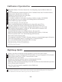
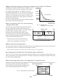
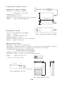
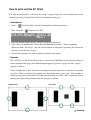
4-2 Leakage Current Hot Check
1) Plug the AC cord directly into the AC outlet. Do not use an isolation transformer for this check.
2) Connect a 1.5KΩ 10 watt resistor, paralleled by 0.15µF capacitor, between each exposed metallic parts on the unit and a
good earth ground such as a water pipe, as shown in the figure below.
3) Use an AC voltmeter, with 1000Ω/volt or more sensitivity, to measure the potential across the resistor.
4) Check all exposed metallic parts of the cover (Cable connection, Handle bracket, metallic cabinet.
Screwheads, Metallic overlays, etc), and measure the voltage at each point.
5) Reverse the AC plug in the AC outlet and repeat each of the above measurements.
6) The potential at any point should not exceed 0.75V RMS.
A leakage current tester (FLUKE MODEL : 8000A equivalent) may be used to make the hot checks.
Leakage current must not exceed 0.5 milliamp.
In case a measurement is outside of the limits specified, there is a possibility of a shock hazard, and corrective action must
be taken before returning the instrument to the customer.
AC VOLTMETER
DEVICE
UNDER
TEST
Test all
exposed
metal parts
1.5KΩ
0.15µF
Water pipe
(Earth Ground)
AC OUTLET
Figure. 1 Leakage Current Hot Check
CHAPTER 1. GENERAL DESCRIPTION
OF PRODUCT
CONTENTS
1 Development Background
1-1 Development Objectives --------------------------------------------------------------------------------------------------- 1-1
1-2 Product Concept ------------------------------------------------------------------------------------------------------------- 1-1
1-3 Design Concepts ------------------------------------------------------------------------------------------------------------- 1-3
1-4 PS A200/A100 Spec.Comparison ---------------------------------------------------------------------------------------- 1-4
2 Full Features*
2-1 Full Features / Operation ease --------------------------------------------------------------------------------------------- 1-5
2-2 High Image Quality --------------------------------------------------------------------------------------------------------1-10
2-3 High Grade Design -------------------------------------------------------------------------------------------------------- 1-12
2-4 System Accessories and Software -------------------------------------------------------------------------------------- 1-13
3 Exterior
3-1 Camera -----------------------------------------------------------------------------------------------------------------------1-15
3-2 6-dimensional views -------------------------------------------------------------------------------------------------------1-17
3-3 Nomenclature ---------------------------------------------------------------------------------------------------------------1-18
3-4 User Interface display -----------------------------------------------------------------------------------------------------1-19
4 Specifications
4-1 Camera Specifications -----------------------------------------------------------------------------------------------------1-22
4-2 System Requirements ------------------------------------------------------------------------------------------------------1-28
4-3 Specifications of Major Accessories -------------------------------------------------------------------------------------1-29
5 System
5-1 Accessory compatibility ---------------------------------------------------------------------------------------------------1-31
5-2 System Diagram ------------------------------------------------------------------------------------------------------------1-33
1 Development Background
1-1 Development Objectives
As of November 2001, Canon is responding to a wide range of customer demands with the six series in our line:
the single-lens-reflex EOS 1D and EOS D30, the PowerShot Pro90 IS with 10x zoom lens, the PowerShot G2
with high image quality and advanced features, the highly compact PowerShot S40/S30, the ultra compact IXY
DIGITAL 300/200 and the basic value PowerShot A20/A10.
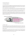
However, as digital cameras are proliferating rapidly recently, we believe there are many potential consumers
who want to enjoy the convenience of digital photography, but who consider the $300 to $400 class such as the
PowerShot A20/A10 too expensive, and ‘toy’ cameras in the $100 and under class to be inadequate. We therefore believe that we can enhance our market share by providing a low-end Canon digital camera for these
consumers, and we are undertaking development of new digital cameras to respond to these demands.
This means that first-time users of digital cameras, and those who mainly want ease of use, are the main targets
for the low-end class (2-megapixel) PowerShot A200 and (1.3-megapixel) PowerShot A100, which will be
distinguished from other brands by a combination of high-end features such as primary filters plus a new image
engine, movie recording and Camera Direct features, and basic features such as a fixed-focus lens and simple
operation aimed at this class of users.
For Digital Camera Beginners
Beyond the Class
yFull Features/Operation Ease
yHigh Image Quality
yHigh Grade Design
For Casual Digital Camera Users
1-2 Product Concept
Because these models are aimed at users purchasing a digital camera for the first time, who want to enjoy
convenient digital photography economically, the PowerShot A200/A100 will be priced as low as possible, while
providing the same capabilities and features as higher-end models as much as possible. The product concept is
therefore “Excelling Classes of Advanced Features with Convenient Operation and High Image Quality with
High Grade Design.”
Also, despite the low price of the PowerShot A200/A100, we propose to foster a new culture of convenient
photo printing for the class of digital camera users who use a PC monitor or TV to display digital photographs, by
providing the Direct Print feature compatible with the CP-10 Card Photo Printer and the CP-100 Photo Printer,
to enable simple credit card or postcard size photo printing at home.
1-1
Full Features / Operation Ease
N - Photo Effect Modes (Vivid color, Neutral color, Low Sharpening, Sepia and Black & White) are
provided
N Direct Print Function for dedicated printers (CP-10 Card Photo Printer and CP-100 Photo Printer)
N - Shutter speed is allowed from 1 to 1/2000 sec.
N - Enabling for On/Off selection of AF-assist Beam
N - Macro Function focuses down to 5 cm
N - Use of widely available size AA battery (2) (primary: alkaline, secondary: NiCd/NiMH)
N - One-click open/close lens cover (dual use for switching between still and movie)
N - Inverted Galilean-type optical viewfinder
N - Reset of all settings by one-touch operation
- Movie recording and playback (selectable pixel size from QVGA and Q2VGA )
- AF Frame (3-point) auto selection (AiAF) and center single-point selection (AF)
N - Magnified playback for convenient image confirmation (from approx. 2x to 10x zoom)
- High continous shooting (approx. 3 images/sec. (PS A100) when LCD monitor is off)
- Eleven-language international GUI support
- Convenient operation using cross-configured buttons, with a new GUI
- Digital zoom function changes viewing angle continuously (4X:PS A200), (3.2X:PS 100)
- Stress free operation with 1.4 sec. interval shooting (OVF:PS A100)
- Built-in flash with four flashing modes
- Low-temperature, polysilicon 1.5-inch LCD monitor with power-saving backlight (approx.120k pixels)
- Total of nine image quality modes (3 recording pixels X 3 compression ratio)
- Rec.-review function (instant erase possible while reviewing)
- High-Speed image Transfer (during playback)
- High-Speed Image Transfer on USB Interface
- Self-Timer Photo Function
High Image Quality
- Primary color filters and signal processing algorithms to get the most of these features
N - High resolution 1/3.2-type 1.2 megapixel* CCD (PS A100), 1/3.2-type 2 megapixel* CCD (PS A200)
N - High-resolution fixed-focus F2.8 lens (35 mm equivalent: 39 mm)
- AF maintains focus at any distance
- Intelligent AE determines optimum exposure in all photographic situations
- High-precision white balance (Auto, plus five preset positions)
- Wide range of ISO-equivalent speed settings (Auto, ISO 50(A200)-64(A100)/100/200/400 equivalent)
- Noise reduction feature for high S/N
- Super Fine mode image quality comparable to that of RAW mode
* Camera effective pixels
N : New features equiped for new cameras which will be launched in spring 2002.(including improved existing features)
The explanations of some features shown in gray letters are omitted in section 2.
1-2
High-grade Design
- 2:1 sideways layout
N - Graphical symbols at the top of the screen show major functions at a glance
System Accessory / Application Software
N - Waterproof case submersible to 30m
N - Compact power adapter for power supply
N - Full featured application softwares
Canon Image Gateway* compliance for image upload, album creation, on-line photo printing, etc*.
ZoomBrowser EX 3.3/3.4 (Win)/ImageBrowser 2.3 (Mac) featuring improved ease of operation
PhotoRecord 1.4 (Win) for easy layout and printing of pictures
PhotoStitch 3.1 for creating precise panoramic pictures
RemoteCapture 2.4/2.5 for transfering images to the PC and capture control from the PC
Twain Driver 4.3/4.5 / WIA Driver 4.3/4.5 (Win)
Plug-in module 4.3/4.5 / USB mounter 1.4/1.6 (Mac)
RAW Image Converter 2.0 for processing RAW images
Apple QuickTime 5.0
CP-10 PrinterDriver.
* for Japanese market only
N : New features equiped for new cameras which will be launched in spring 2002.
(including improved existing features)
1-3 Design Concepts
z Freshness
A fresh and intimate appearance to suit an entry model that is easy for anyone to use
- “Bright Silver” color for a bright, cheerful appearance
- Exterior design using plastic skillfully for excellent handling
- Details utilizing different materials such as clear plastic, chrome and elastomer
z Sincerity
Basic ease of use camera intended to distinguish itself from the cheap “Toy Cameras”
- Adhering to the “box and circle” design
- Use of circle motif and lens cover with ingenious operation
- The tripod mounting hole and lens light share the same axis to suit panoramic photography
- Cross-configured buttons and control buttons for separate functions, with just enough for necessity
- Sideways layout for easy holding and inserting/removing from pocket or bag
1-3
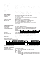
1-4 PS A200/A100 Spec.Comparison
zPowerShot A200 & PowerShot A100
Pow erShot A200
CCD
Color filter
Lens(focal length 35mm film equivalent)
Digital zoom
Optical view finder
LCD monitor
AF
Normal shooting range
Macro shooting range
Shutter
Shutter speed
Light metering method
Exposure compensation
ISO equivalent speed
Flash
White balance
Shooting mode
Photo effect mode
Continuous shooting
Recording media
File format
Compression
Recording pixels
Enlarged playback
Direct print
Interface
Battery
Dimensions(W×H×D)
Weight
Normal
Macro
L
M
S
Pow erShot A100
1/3.2 type 2.0M (effective), about 2.1M (total)
Primary color filter
5mm (39mm) F2.8
4×
Reverse Galilean
1.5"low temp.p-si TFT
Selectable 3 focusing points(AiAF) or 1(Center), w ith AF lock
20cm- ∞
5-20cm
Mechanical shutter + electronic shutter
1-1/2000 sec
Evaluative
±2.0EV (1/3EVstep)
Auto/50/100/200/400
At Auto setting, camera automatically adjusts speed according to ambient light,
from ISO 64 to ISO 150 equivalent
20cm-2m
5-20cm
Auto + Preset (5 positions)
Auto/manual/stitch-assist/movie
Vivid/Neutral/Low sharpening/Sepia/BW
** images/s, Large/Fine LCD monitor off
CF (Type I)
DCF (Applied to Exif2.2),DPOF
SuperFine/Fine/Normal × L/M/S (9 patterns)
1600×1200
1024×768
640×480
about 2-10×
possible (CP-10/CP-100)
USB
AA alkaline×2, AA NiMH×2, Compact pow er adapter
110×58×36.6
Approx. 175g
1-4
1/3.2 type 1.2M (effective), about1.3M (total)
←
←
3.2×
←
←
←
←
←
←
←
←
←
Auto/64/100/200/400
At Auto setting, camera automatically adjusts speed according to ambient light,
from ISO 64 to ISO 150 equivalent
←
←
←
←
←
3 images/s, Large/Fine LCD monitor off
←
←
←
1280×960
←
←
←
←
←
←
←
←
2 Full Features
2-1 Advanced Features with Convenient Operation
z Photo Effect Modes (Vivid color, Neutral color, Low sharpening, and Sepia and Black & White)
are provided
The color modes in the PowerShot G2 and PowerShot S40/S30 are included in the PowerShot A200/A100, with
a Low sharpening mode added to the Vivid, Neutral, Sepia and Black & White modes, for a total of five modes.
Also, for the PowerShot A200/A100, settings are made by special-purpose buttons instead of the mode dial
setting system on the PowerShot G2 and PowerShot S40/S30. So, for example, color effects can be applied
while making a movie. Table 2-1 shows the contents and effects.
Photo Effect
Description
Vivid color
Emphasizes contrast and color intensity
Neutral color Reduces contrast and color intensity
Low sharpening Reduces edge's emphasis
Sepia
Adds sepia toning to the color information
Black & White Sets the color gain to "0," producing a black & white image
Effect
Produces a vivid and sharply-defined image
Produces a subdued, plain image
Produces a mild image
Creates an old-fashioned appearance
Produces a binary image with sharp contrast; used for text
Table 2-1 Contents and Effects of Photo Effect Setting
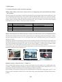
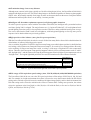
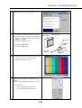
z Direct Print Function for dedicated printers (CP-10 Card Photo Printer and CP-100 Photo Printer)
The PowerShot A200/A100 includes the Direct Print function to enable high quality image printing by connecting with a special cable to Canon’s CP-10 Card Photo Printer and CP-100 Photo Printer, newly developed for
postcard size prints.
All printing operations are performed from the camera, including selection of frame/no-frame, date on/off, and
adjusting the print area to match the image aspect ratio when creating card-size prints with no frames. The print
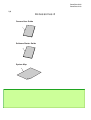
area can be positioned by the upper side, center, or lower side (see Photo 2-1). With card-size printing, single
stickers the size of the whole print sheet can be made, as well as eight stickers per card sheet.
A new image engine in the camera provides the high-speed color processing calculations for printing that are
normally performed by the PC printer driver.
Photo 2-1 Printing area (Card size print)
z Shutter speeds is allowed from 1 to 1/2000 sec.
The PowerShot A200/A100 provides up to 1/2000 second shutter speed, the highest level available in this class
of camera. Combining this speed with the F5.6 aperture setting provides photos with a maximum of EV 17, for
photography in bright environments and minimal blurring of fast-moving objects.
Also, when the one-second slow shutter speed is combined with the F2.8 aperture setting, photos up to EV 3 can
be taken, and in combination with the slow synchro flash mode, portrait photography with night background is
possible.
1-5
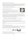
zEnabling for On/Off selection of AF-assist beam
Many of the PowerShot series are equipped with an assist light to ensure proper autofocus when subject
brightness is below a certain level. However, when photographing animals in a dark environment, they may react
to the AF-assist beam by running away, preventing the desired photo from being taken in such situations.
The PowerShot A200/A100 therefore includes the capability to turn the AF-assist beam on and off, so that
photos can be taken without it in situations like the above.
34 mm/1.3 inch
*When the surrounding light level is extremely low, the AF function may be unable to determine the
proper focus. In such cases, the focus is fixed at a specific point.
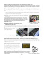
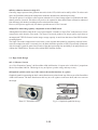
zMacro Function focuses down to 5 cm
The PowerShot A200/A100 includes a macro function that can photograph
as close as 5 cm from the subject. The area of the photo is about 46 × 34 mm
with the PowerShot A200, and about 47 × 35 mm with the PowerShot A100,
46 mm/1.8 inch
which is the smallest area that can be photographed so far by any camera in
Photo 2-2 Max. capturing area
the PowerShot/IXY series’.
zUse of widely available size AA battery with (2) (primary: alkaline, secondary: NiCd/NiMH)
For convenience, the PowerShot A200/A100 can be powered by AA-size batteries. This convenience is especially significant because only two batteries are required instead of four, such as in the PowerShotA20/A10.
While the primary battery type is alkaline, NiCd*2 or NiMH batteries may also be used, so the user can choose
the best battery type according to the usage situation and environment.
*1 Manganese batteries cannot be used. Also, because alkaline batteries vary considerably among
manufacturers, it is preferable to use brands recommonded by Canon.
*2 NiCd battery capacity also varies considerable among manufacturers, so we do not recommend their use.
zOne-click open/close lens cover (dual use for switching between still and movie)
The lens cover of the PowerShot A200/A100 can be opened and closed with one touch. Also, clever use of two
springs (patent application planned) for the opening and closing mechanism provides convenient operation with
minimum effort.
Additionally, a one-touch selection is provided to use the lens cover for switching between still images and
movies.
zInverted Galilean-type optical viewfinder
The reverse Galileo-type optical viewfinder system was adopted instead of the previous actual-image system. In
the reverse Galileo-type system, the object lens is concave and the eyepiece is convex. The mechanism is simple
(2 lenses), resulting in clear visibility and suitable compactness for a small camera.
Further, the eye relief being as long as 16 mm, excellent observation is also possible for people wearing eyeglasses.
Eye-point
Fig. 2-1 Optical viewfinder
16mm
(0.63inch)
zReset of all settings by one-touch operation
The user can make many settings on the PowerShot A200/A100 LCD, and by pressing the menu button for five
seconds, all settings can be canceled (returned to defaults).
1-6
z Movie recording and playback (selectable pixel size from QVGA and Q2VGA )
The PowerShot A200/A100 can record movies in QVGA (320 × 240 pixels) and Q2VGA (160 × 120 pixels)
formats at 20 frames/second (15 f/s with the PowerShot A100). Up to ten seconds continuous recording is
possible in QVGA, and up to 30 seconds in Q2VGA format.
The focus, exposure, WB and zoom settings are set at the start of recording, and are used until finished recording. While recording, the available time remaining is displayed on the LCD. The movie file format is Motion
JPEG.
* When the remaining capacity of the CF is less than the buffer memory capacity, recording can continue until the
time determined by the remaining capacity of the CF.
z AF Frame (3-point) auto selection (AiAF) and center single-point
selection (AF)
The PowerShot A200/A100 incorporates both the 3-point AiAF method
in which the camera automatically determines the proper AF frame from
three measurement points, and the standard AF method that uses a single
center point, so the user can select the best method depending on
photographic conditions.
When AF frame is selected, frame turns on to green.
z Magnified playback for convenient image review
(from approx. 2x to 10x zoom)
Photo 2-3 3-point AiAF
During playback, the displayed image can be magnified with continuous zoom from two to ten times. Also, by
pressing the SET button when setting magnification, the magnification steps in three preset ratios of 2.5, 5 and
10x.
Magnified images can be scrolled
to view a desired region.
Photo 2-4 Magnified playback
<Original>
<10X>
z High speed continuous shooting (approx. 3 images/sec.(PA A100) when LCD monitor is off)
The PowerShot A100 can shoot continuous pictures at up to approx. 3 images per second (PS A200 : approx. 2
images per second). The maximum number of continuous images that can be taken are 10 (PS A100), 7 (PS
A200) in the Large/Fine mode.
z Eleven-language international GUI support
The LCD menu on the PowerShot A200/A100
supports eleven languages, expanding the number
of native-language environments for the camera.
The following languages are supported.
z Convenient operation using cross-configured buttons, with a new GUI
Despite the PowerShot A200/A100 being a low-priced model, a cross-configured
button arrangement is adopted, resulting in very easy operation. The GUI layout
Fig. 2-2 Cross-configured buttons
is also simplified.
1-7
zDigital zoom function changes viewing angle continuously (4X: PS A200), (3.2X: PS 100)
Although the PowerShot A200/A100 have a single-focus lens,
the PowerShot A200 incorporates 4x digital zoom, and the
PowerShot A100 incorporates 3.2x digital zoom. So the
PowerShot A200 functions as a 39-156 mm zoom equivalent,
and the PowerShot A100 as a 39-125 mm zoom equivalent
(relative to a 35-mm film camera). However, because of the
characteristics of digital zoom, image quality is degraded at
the higher telephoto settings.
Even so, the actual effective pixels at the maximum telephoto
limit is about 120k (OSGA-equivalent).
Recording Pixels
(Image Quality)
1600X1200
1280X960
PowerShot A200
1024X768
800X600
640X480
400X300
PowerShot A100
35
105
140
Focal length (mm)
(35mm film equivalent)
zStress free operation with 1.4 sec. interval shooting
(during OVF:PA A100)
The new image engine installed in products since Spring
2001 is incorporated in the PowerShot A200/A100,
providing a photo interval of approx. 1.4 seconds (during
OVF:PS A100) to minimize stress on the user.
Furthermore, functions that usually require a long
processing time such as camera startup, digital zoom,
image transfer during playback and display magnification
can be performed with minimal stress.
70
Fig. 2-3 Digital zoom
(Magnify vs. Image quality)
SW1
ON
Next SW1
ON
SW2 Exposure Exposure
ON starts
stops
Shutter time lag
approx. 0.05 sec.
Shutter speed
Shooting Interval : approx. 1.4 sec.
* The shortest interval from one photo to the next
(details are shown in Fig. 2-4: Large/Fine mode).
However, this value depends on the subject.
Fig. 2-4 Picture taking sequence
zBuilt-in flash with four-flashing modes
The built-in flash of the PowerShot A200/A100 can be set to four lighting modes: auto red-eye reduction, auto
on (off) and slow synchro, according to the photographic situation.
* When the flash is charging, the LCD moniter turns off owing to power saving function.
zLow-Temperature Poly-Siillcon TFT LCD Monitor (approx. 120k pixels)
The LCD (1.5-inch) monitor in the PowerShot A200/A100 adopts a power-saving white LED backlight. Also,
the low-temperature polycrystalline silicon TFT with about 120,000 pixels, the highest resolution in this class,
provides extremely sharp images.
zTotal of nine image quality modes (3 recording pixels X 3 compression ratio)
With the PowerShot A200/A100, image quality can be selected from nine combinations of recording pixel resolution (large, medium and small) and compression
Prints for high image quality
Display
ratio (super fine, fine and normal), supporting a wide
Large
Large
Large
variety of photographic applications for the user.
Superfine Fine
Fig. 2-5 Image quality for each purpose
Archive
1-8
Normal
Nedium Nedium
Nedium
Superfine Fine
Normal
Small
Superfine
Small
Fine
Small
Normal
Net image
zImmediate image review (can erase while reviewing)
The PowerShot/IXY series displays an image for two seconds (or ten seconds, depending on setting)* for
confirmation immediately after the photo is taken. The PowerShot A200/A100 supplements this feature with the
Erase One Image mode, activated by the button with the same name.
This feature allows an undesired image to be erased immediately after the photo is taken, so it does not take up
memory space.
* An image is displayed continuously on the LCD monitor while the shutter button is pressed, and if the
SET button is pressed while an image is displayed.
1-9
2-2 High Image Quality
z Primary color filters and signal processing algorithms to get the most of these features
The PowerShot A200/A100 adopts the primary color filters and
signal processing algorithms, optimized for them, that we have used
in products since Spring 2001.
Although primary color filters are inferior to complementary color
filters with regard to brightness resolution and S/N, they are
excellent for color reproduction, so their use in digital cameras
Primary color filter Complementary color
has recently been growing. However, the important technological
filter
considerations of inferior brightness resolution and S/N remain.
Fig. 2-6 Filter arrangement
Canon has developed signal processing algorithms optimized for
primary color filters, and the newly incorporated image engine to
Sensitivity
Canon’s primary color
handle these algorithms effectively removes false colors and
Secondary
enhances S/N. Also, by redesigning the optics, enhancing
Color
color filter
reproduction
sensitivity and maintaining good color reproduction, brightness
resolution and S/N performance comparable to complementary
Primary
color filter
color filters is achieved.
Conventional
processing
z High Resolution: 1/3.2-type 1.2 megapixel CCD (in PS A100),
1/3.2-type 2 megapixel CCD (in PS A200)
Fig. 2-7 Filter’s types
and positionings
The PowerShot A200 adopts the newly developed 1/3.2-type
2-megapixel* CCD (1.2-megapixels for the PowerShot A100). These CCDs have almost the same number of
pixels as those in the PowerShot A20/A10, but the screen size is reduced from 1/2.7 type to 1/3.2 type, making
the smaller optical system possible.
However, when images photographed with the PowerShot A200/A100 are printed on the CP-100, the resolutions are as shown in Table 2-2.
Postcard size
L size
Card size
(148mm x 100mm) (120mm x 82mm)
(86mm x 54mm)
Table 2-2
Print size and image
resolution (calculated value)
obtainable with PS A200/A100
PowerShot A200
(1600 x 1200)
4.5 lp/mm
5.4 lp/mm
5.9 lp/mm*
PowerShot A100
(1280 x 960)
3.6 lp/mm
4.3 lp/mm
5.9 lp/mm*
* Although the camera can achieve 7.9lp/mm (PS A200) or 6.3lp/mm (PS
A100) of resolution , this resolution is regulated by the printer’s lower reso
lution.
z High-resolution single-focus F2.8 lens (35-mm equivalent: 39 mm)
The PowerShot A200/A100 incorporates a newly developed 5-mm F2.8 single-focus lens (35-mm equivalent:
39 mm). The lens configuration consists of five groups of five elements including an aspherical (on one side)
lens, and focusing is achieved by moving all five lens elements of the system as a unit.
The optical capability is sufficient to support a CCD with resolution of 2-megapixels at 1/3.2 element pitch, and
each aberraction is minimized by the aspherical lens.
1-10
zAF maintains image focus at any distance
Although most cameras in this class typically use fixed-focal-length (pan) focus, the PowerShot A200/A100 is
equipped with high-precision AF. This allows sharp images to be obtained regardless of distance to photographic
subject. Also, the normally unusable focal range for most such cameras between the macro focal plane and the
minimum normal focal plane from 5 cm to infinity, becomes possible.
zIntelligent AE determines optimum exposure in all photographic situations
To achieve precise exposure control with the PowerShot A200/A100, the intelligent AE system that has been
used since Spring 2001 is adopted. The major features are (1) 3-point AF-linked AE, (2) low brightness/background lighting correction, and (3) close-up flash correction. Therefore, under conditions usually prone to exposure errors, and when the flash is used in low brightness, with background lighting or close up, more precise
exposure can be obtained than was previously possible.
zHigh-precision white balance (auto, plus five preset positions)
With the PowerShot A200/A100, the whole screen is divided into many blocks from which calculation data for
white balance is collected, allowing precise control.
Also, as with the PowerShot G2/S40/S30, the Fluorescent Lamp preset white balance position is subdivided into
two settings, called Fluorescent Lamp and Fluorescent Lamp H, for a total of five setting positions. Recently,
color rendering of fluorescent lamps has varied, covering a wide range of high and low color temperature
objects. Therefore, the Fluorescent Lamp position supports relatively lower color temperatures such as “white”
and “daylight white”, and the Fluorescent Lamp H position supports relatively higher color temperatures such as
“daylight color”. The regular light bulb position is also used for incandescent-colored fluorescent bulbs.
Types of Fluorescent Light
Three-wavelength type fluorescent light designed to mimic incandescent light
Daylight white fluorescent light, white fluorescent light,
daylight white three-wavelength type fluorescent light
Daylight fluorescent light, daylight three-wavelength type fluorescent light
White Balance
Preset Position
Incandescent
Fluorescent
Fluorescent H
Table 2-3 Types of fluorescent light and white balance preset position
zWide range of ISO-equivalent speed settings (Auto, ISO 50(A200)-64(A100)/100/200/400 equivalent)
The PowerShot A200/A100 user can select ISO speed equivalent to film ratings of ISO 50(64), 100, 200 and
400. For example, in a bright environment where there is no need to worry about camera shake, the ISO 50(64)
setting can be selected to provide low noise conditions for highest image quality, and in a dark environment, the
ISO 400 setting can be selected to minimize the effects of camera shake. During auto operation, the camera
selects the optimum value from 50(64) to 140 (50(64) to 150 with the flash, or for movies 50(64) to 280 for
QVGA, and 50(64) to 560 for Q2VGA.)
1-11
z Noise reduction feature for high S/N
Generally, longer exposure times generate more noise in the CCD, which can be readily visible. To reduce such
noise, the PowerShot A200/A100 incorporates automatic internal noise reduction processing.
The specific process is as follows: after exposure when the iris is closed, image capture is repeated for the same
shutter period as just used. This allows only noise to be captured as data, and this data can then be subtracted
from the image just obtained, resulting in noise reduction in the image.
However, this process applies only for shutter speeds between 1/8 and 1 second.
z SuperFine mode image quality comparable to that of RAW mode
Although the PowerShot A200/A100 is a low-priced model, it includes a “Super Fine” mode that uses a lower
compression ratio than the Fine mode. The Super Fine mode produces an image quality equivalent to
uncompressed TIFF file format, but the image storage capacity is much less than that of the JPEG baseline
recording format.
The Super Fine mode compression is not lossless, so the original data cannot be completely restored, but because the compression ratio is extremely low, the block distortion peculiar to JPEG is practically eliminated.
Also, this mode is good for general use because of the short processing time and ability to be played back even
without the TWAIN driver, because of the ordinal JPEG baseline format.
2-3 High Grade Design
z 2 : 1 Sideways Layout
As a “New Generation Camera”, the PowerShot A200/A100 has the 2:1 aspect ratio “wide & low” proportions
like the PowerShot S40/S30. This design is easy to slip into a pocket or bag, and easy to carry.
z Graphical symbols on the top of the camera show main functions at a glance
Graphical symbols representing the basic camera functions are printed on the top of the screen of the PowerShot
A200/A100 cameras. The basic functions are this easy to see at a glance on the store shelf, and serve to accent
the design.
Photo 2-5 PowerShot A100
Fig. 2-9 Graphical symbols at the top
1-12
2-4 System Accessories and Software
z Waterproof case submersible to 30 m
The PowerShot A200/A100 fits into the WP-DC500 Waterproof Case, submersible to 30 meters for diving and
snorkeling.
* We intend to publish information later about the special technologies used in the waterproof case.
z Special-purpose compact power adapter
The PowerShot A200/A100 can be powered from household power source using the CA-PS800 Compact
Power Adapter.
z Full featured application software
{Usage of Canon Image Gateway
When an PowerShot A100/A200 purchaser registers as a member, they can receive the following on-line
photo services at Canon Image Gateway:
-Image upload service
-On-line photo album service
-Stored image printing service
-Photo collection creating service (My Book)
-Cellular telephone support (name undetermined)
-DP Service: prints up to L size, double-sided
Plan
* for Japanese market only
Fig.2-10 CIG Top scren
{ZoomBrowser EX 3.3(A100)/3.4(A200) (Win)/ImageBrowser 2.3(A100/A200) (Mac) featuring
improved ease of operation
ImageBrowser 2.3 (Mac) is supported by Mac OS 10.1 (though not by Mac OS 10). In the previous
version, rotating a JPEG image required the image to be decompressed, then rotated as RGB data, and
then recompressed as the JPEG image. In this version, JPEG images are rotated as is, so image data loss
is eliminated.
{Photorecord 1.4 (Win) for easy layout and printing for many pictures
Unchanged from previous version, for convenience.
{PhotoStitch 3.1 for creating precise panoramic pictures
Unchanged from previous version, for convenience.
{RemoteCapture 2.4(A100)/2.5(A200) for transfering images to the PC and capture control from
the PC
Unchanged from previous version, for convenience.
1-13
{Twain Driver 4.3(A100)/4.5(A200) / WIA Driver 4.3(A100)/4.5(A200) (Win)
Unchanged from previous version, for convenience.
{Plug-in module 4.3(A100)/4.5(A200) / USB mounter 1.4(A100)/1.6(A200) (Mac)
Unchanged from previous version, for convenience.
{RAW Image Converter 2.0(A100) for processing RAW images
From this version, the TWAIN driver and UI share the same development prosess.
Also, loading RAW data into ZoomBrowser EX 3.3/3.4 (Win) and ImageBrowser 2.3 (Mac) causes
RAW Image Converter 2.0 to load automatically for developing and saving the data.
* This application is not available for the PowerShot A200 and A100 because they cannot record RAW data.
{Apple QuickTime 5.0
Unchanged from previous version, for convenience.
{CP-10 PrinterDriver.
Unchanged from previous version, for convenience.
1-14
3 Exterior
3-1 Camera
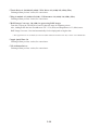
Bright-silver
Smoke-gray
Photo 3-1 PowerShot A200 front
Titanium-metalic
Photo 3-2 PowerShot A200 rear
Photo 3-3 PowerShot A200 top
* These photos have slightly different exterior from mass-production model because of prototype.
1-15
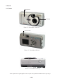
Bright-silver
Smoke-blue
Photo 3-4 PowerShot A100 front
Titanium-metalic
Photo 3-5 PowerShot A100 rear
Photo 3-6 PowerShot A200/A100 operation part
* These photos have slightly different exterior from mass-production model because of prototype.
1-16
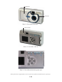
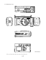
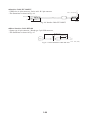
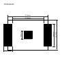
39.8(1.57)
36.6(1.44)
3-2 6-dimensional views
58.0(2.28)
110.0(4.33)
Unit:mm(inch)
* The size of PowerShot A200 is the same as PowerShot A100.
1-17
3-3 Nomenclature
Shutter Button
Optical Viewfinder
Window
Strap
Eyelet
Lens
Lens Cover
Flash
Date Battery
Holder
CFCard Slot
/Battery Cover
Tripod Socket
Button
(Display)Button
(Erase)Button
Zoom Button
Shooting:
(Tele photo)/
(Wide Angle)
Replaying:
(Magnifying images)/
(Index Views)
Power/Replay Button
(Exposure Compensation)/
WB (White Balance)/
(Photo Effect)
Button
Indicators
Viewfinder
LCD Monitor
(Flash)/
Button
(Continuous shooting)
(Self-Timer)/ Button
(Macro)/
(Infinity)/
Button
SET Button
* In PowerShot A200,the model name display on the front changes into A200 from A100, and
picture display changes into 2.0 from 1.2.
1-18
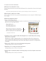
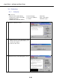
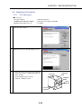
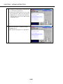
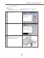
3-4 User Interface display
Rec.Menu
(A100 Rec.mode: Auto)
<Compression>
<Digital Zoom>
y Super Fine
y Fine
y Normal
y On/ y Off
<Review>
<AF-assist Beam>
<File No. Reset>
y Off/ y 2Sec./ y 10Sec.
y On/ y Off
y On/ y Off
<Resolution>
y L : 1280X960
y M : 1024X768
y S : 640X480
Set up...
<Beep>
<Date/Time>
<Language>
y On/ y Off
y
y
y
y
y
y
* Although the layout of these screens may differ slightly from that of
the final product, there is no change operationally.
1-19
English
y Italiano
Deutsch
y Norsk
Francais
y Svenska
NederLands y Espanol
Dansk
y
Suomi
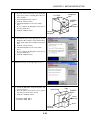
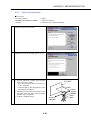
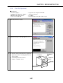
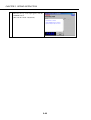
<Information during shooting>
Shooting mode: Auto/Manual/Stitch Assist
.............
..........
ISO Speed: Auto/64/100/200/400 ..................
.........
......
Compression: Resolution:
/Super Fine/Fine/Normal.........
3
Photo Effect: Off/Vivid/Neutral/Low Sharpening/Sepia/ B/W
White Blance: Auto/Daylight/Cloudy/Tungsten/Fluorescent/Fluorescent H
Exposure Compensation:-2∼+2
Focus: Normal/Macro/Infinity/
Remaining Image
Capacity
Drive: Single Shot/Shooting continuously/
Self-timer(10sec)
Flash: Red-eye reduction auto/ON/(OFF)/Slow-syncro speed
1-20
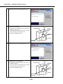
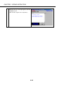
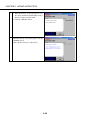
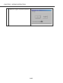
DPOF
<Set up>
<Order>
Print
(order)
<Print Type>
Transfer Order (DPOF)
y Standard
<Date>
<File No>
y On/ y Off
y On/ y Off
y Index
y Both
Transfer
Mark all
1-21
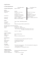
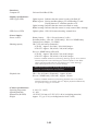
4 Specifications
4-1 Camera Specifications
( PowerShot A200 )
Approx. 2 million
( PowerShot A100 )
Approx. 1.2 million
-Total pixels
-Filter array
Interline
4.48 (H) X 3.38 (V) mm
(0.18 X 0.13 in.
equivalent to 1/3.2-inch size
2.75 (H) X 2.75 (V) micron
(0.108 X 0.108 m-in.)
Approx. 2.1 million (1,704 X 1,257)
Primary color filter (Beyer)
<<
4.48 (H) X 3.36 (V) mm
(0.18 X 0.13 in.)
equivalent to 1/3.2-inch size
3.5 (H) X 3.5 (V) micron
(0.14 X 0.14 m-in.)
Approx. 1.3 million (1,344 X 971)
<<
<Lens>
-Focal length
-f/number
-Lens construction
5 mm (39 mm : 35mm film equivalent)
2.8
5 pieces in 5 groups (include 1 aspherical lens)
<Camera effective pixels>
<CCD>
-Reading format
-Image size
-Unit cell size
<Focusing range> (Measured from tip of lens)
-Normal
20 cm (0.67 ft.) -infinity
5 cm (0.17 ft.) - 20 cm (0.67 ft.)
-Macro
*Max.shooting area PS A200 : 46 X 34 mm (1.8 X 1.3 in.)
PS A100 : 47 X 35 mm (1.9 X 1.4 in.)
5 m (17 ft.) - infinity
-Landscape
<Optical viewfinder>
-Type
-Magnification
-Coverage
Inverted Galilean finder
0.45
Vertical : 80% Horizontal : 80%
<LCD monitor>
-Type
-Effective pixels
-Display size
-Coverage
Low-temperature polycrystalline silicon TFT color LCD
117,600 (490 (H) X 240 (V))
38 mm diagonal (1.5 inch)
100%
<Focusing>
-Control system
-Focusing points
TTL AiAF (3 focusing points) / TTL AF (Selectable)(1 focusing point)
(Focus lock is available.)
3 focusing points or 1 focusing point (center)
<Exposure control>
-Light Metering method
-Exposure method
-Exposure compensation
Evaluation (Linked with focusing point)
Program AE
+/-2.0EV (at every 1/3-stop)
1-22
<Aperture and shutter>
-Shutter type
-Shutter speed
-Aperture range
<White balance>
-Mode
Mechanical shutter and electronic shutter
1 - 1/2,000 sec.
(1 - 1/6 sec. shutter is available at flash-off or slow-syncro. in Manual mode.)
(Slow shutter of 1/6 sec. and more operates with noise reduction.)
f/2.8 / f/5.6
TTL auto white balance, pre-set white balance
(Available settings : Daylight, Cloudy, Tungsten, Fluorescent or Fluorescent H)
<Flash (Built-in)>
-Operation modes
-Flash range
Red-eye reduction auto, Auto, On, (Off), Slow-syncro.
20 cm - 2 m (0.67 - 6.7 ft)
* The flash photograpy are not allowed in macro mode due to inaccurate
exposure control.
(When sensitivity is set to ISO100 equivalent.)
1/30 sec. or faster (Normal) / 1 sec. or faster (Slow-syncro.)
10 sec. or shorter (full flash, battery voltage = 3 V)
-Flash syncro. speed
-Recycling time
* When the flash is charging, the LCD monitor turns off owing to power
saving function.
<Shooting specifications>
-Shooting modes
-Color effects
-Continuous shooting modes
Auto / Manual / Stitch assist / Movie
Vivid color / Neutral color / Low sharpening/ Sepia / Black & White
Approx. 2 images/sec.(PS A200) (Large/Fine, LCD monitor OFF)
Approx. 3 images/sec.(PS A100) (Large/Fine, LCD monitor OFF)
Number of
L/SF L/F L/N M/SF M/F M/N S/SF S/F
shooting pictures PS A100 7
10
20
10
15
29
22
32
PS A200
5
7
14
9
14
26
19
28
S/N
56
50
Operates with 10 seconds countdown.
Auto, ISO50(PS A200 only), 64(PS A100 only), 100, 200 and 400
(At Auto setting, camera automatically adjusts speed according to ambient
light, from ISO50 (PS A200) / 64 (PS A100) to ISO150 equivalent.)
-Digital zoom
PS A200 : 4x
PS A100 : 3.2x
-Shutter release from PC
Use of “Remote Capture” software (include) when USB connection
-Camera wake-up time/ Release time lag (sec.)
-Self timer
-ISO equivalent speed
Mode
Finder
Shooting EVF
OVF
Playback -
Wake-up time
Release time lag
PS A100|PS A200 PS A100|PS A200
2.4
2.5
0.07
0.08
1.7
1.7
0.05
0.08
3.7
2.8
-
*Varies with shooting modes
-Shooting interval (*right table)
Shooting
Shooting Interval (sec.)
Finder N/M
PS A100 | PS A200
Mode
Auto
EVF Normal
1.6
1.8
Macro
2
2.4
OVF Normal
1.4
1.6
Macro
1.6
1.8
*The actual shooting interval is that of shutter
time (sec.) added to the above data.
<Recording specifications>
-Compression mode
Super Fine, Fine or Normal
-Number of recording pixels
Large : 1,600 X 1,200 (PS A200) / 1,280 X 960 (PS A100)
Medium : 1,024 X 768
Small : 640 X 480
Movie : 320 X 240 (20fps,Approx.9sec.:A200), (15fps,Approx.14sec.:A100)
160 X 120 (20fps,Approx.26sec.:A200), (15fps,Approx.30sec.:A100)
1-23
-File format
Design rule for Camera File system (DCF*)(Exif 2.2)
* “DCF” is an abbreviation of “Design rule for Camera File system” standardized by Japan
Electronic and Information Technology Industries Association (JEITA), however a use of this
abbreviation is allowed in Japan only due to trademark rights. Exif 2.2 records shooting
parameters useful for the image correction processing performed at the time of printing.
-Recording format
-Storage media
-Storage capacity
Digital Print Order Format (DPOF) Version 1.1
Still image : JPEG
Movie
: Motion JPEG
CompactFlash™ (CF) card (Type I)
PS A200
File Size
FC-8M
FC-16M
FC-32M
FC-64M
FC-128M
L / SF
L/F
L/N
M / SF M / F
M / N S / SF
S/F
957KB 611KB 302KB 450KB 294KB 155KB 208KB 141KB
7
11
24
16
24
46
35
50
15
24
48
32
49
92
70
99
31
49
99
67
102
189
143
206
64
100
200
135
205
379
288
415
128
200
401
271
412
760
577
831
S/N
79KB
87
172
353
707
1417
L / SF
L/F
L/N
M / SF M / F
M / N S / SF
S/F
693KB 450KB 228KB 450KB 294KB 155KB 208KB 141KB
10
16
32
16
24
46
35
50
21
32
64
32
49
92
70
99
43
67
131
67
102
189
143
206
88
135
263
135
205
379
288
415
177
271
528
271
412
760
577
831
S/N
79KB
87
172
353
707
1417
PS A100
File Size
FC-8M
FC-16M
FC-32M
FC-64M
FC-128M
PS A200 (Movie)
PS A100 (Movie)
320×240
File Size 380KB/sec.
FC-8M
18 sec.
FC-16M
36 sec.
FC-32M
76 sec.
FC-64M
152 sec.
FC-128M
305 sec.
160×120
130KB/sec.
48 sec.
97 sec.
198 sec.
399 sec.
799 sec.
320×240
160×120
File Size 285KB/sec. 98KB/sec.
FC-8M
24 sec.
63 sec.
FC-16M
49 sec.
126 sec.
FC-32M
100 sec.
263 sec.
FC-64M
201 sec.
527 sec.
FC-128M
404 sec. 1056 sec.
* Any documents to be distributed outside the company should
state that Above-written figures are measured under Canon’s
standard shooting conditions and may vary depending on the
scene, subjects or camera settings.
-Tone reproduction
<Playback specifications>
-Playback modes
-Direct print
-Magnify
-Vertical and horizontal
conversion
<Erasing specifications>
-Erasing modes
Luminance signal : 8 bits
Color signal
: 8 bits (Cr / Cb)
Single, Index (9 thumbnail images), Magnification or Slide show
Image output to dedicated printer (CP-10, CP-100)
Approx. 2X to 10X on built-in LCD monitor (Zoom)
Vertical and horizontal conversion can be set on each image.
(Both LCD and Video Out play an image according to setting.)
Single image
All images
(When “All images” is set, any images in the CF card captured with another
digital camera or peripheral device (DCF format) are erased. Regarding
Canon digital cameras, images taken by PowerShot Pro70 or prior
models are not erased. Images taken by PowerShot A50 (DCF format) or
latest models are erased (except EOS D2000/D6000).
However images which are protected are not erased.
1-24
<Interface>
-Computer I/F
<Display specifications>
-LED (Upper LED)
-LED (Lower LED)
<Power Supply>
-Power sources
-Shooting capacity
Universal Serial Bus (USB)
Lights in green : Indicates that the camera is ready with flash off.
Blinks in green : During start/Recording to CF card/Reading CF card/
Erasing data on CF card/Data transfer to PC
Lights in orange : Indicates that the camera and flash are ready.
Blinks in orange : Indicates that the camera is ready (camera shake warning)
Lights in yellow : SW1 ON in macro shooting / manual focus
Primary battery : LR 6 / Size AA battery (2 cells)
Secondary battery : (Size AA / NiCd battery), Size AA / NiMH battery
Compact power adapter : CA-PS800
LR 6 / Size AA battery (Panasonic)
LCD ON : Approx. 90 (A200) / 100 (A100) images
LCD OFF : Approx. 300 (A200) / 380 (A100) images
Size AA / NiMH battery (NB-1AH)
LCD ON : Approx. 200 (A200) / 210 (A100) images
LCD OFF : Approx. 550 (A200) / 630 (A100) images
* Canon’s standard conditions of measuring shooting capacity are as follows:
Normal temperature (23 Celsius degrees). LCD viewfinder is ON. Shoot
images with 20 seconds intervals. Use flash at every 4-time shootings.
Turn camera off and on at every 8-time shootings.
* Whth alkaline batteries the shooting capacity is extremely
reduced in low-temperature environments.
-Playback time
LR 6 / Size AA battery (Panasonic) : Approx. 90 min.
Size AA / NiMH battery (NB-1AH) : Approx. 120 min.
* Canon’s standard conditions of measuring playback time are as follows:
Normal temperature (23 Celsius degrees). Repeat playback automatically
at a speed of 1 image per 3 seconds.
<Camera specifications>
-Operating temperature
-Operating humidity
-Dimensions (WxHxD)
-Weight
0 - 40 C (32 - 104 F)
10 - 90%
110 X 58 X 36.6 mm (4.33 X 2.28 X 1.44 in.) (excluding protrusion)
Approx. 175 g (6.17 oz) (excluding batteries and CF card)
1-25
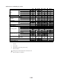
zParameter availability by modes
Auto
Auto
Red-eye reduction auto
ON
OFF
Slow-syncro.
Flash
*
Manual
Stitch
Movie
*
*
Macro
Shooting
*
Single
Continuous
Self-timer
Photo effect
AF frame selection
3 points(AiAF)
1 point
Exposure compensation
White balance
L
M
S
Recording pixels
Movie(320×240)
Movie(160×120)
Superfine
Fine
Compression level
Normal
JPEG
Recording format
M-JPEG
ISOequivalent speed
Digital zoom
AF-assist beam off
*
(1)
*
(1)
*
(1)
*
(1)
Auto only
*
*
*
*
*
*
Auto only
: Default
: Selectable
: Selectable for the first picture only.
--- : Not selectable
: Settings are memorized after switch turns off.
(1) : Not selectable for ”Macro”
{
∇
1-26
Auto only
Auto only
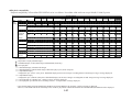
zPlayback compatibility
Playback compatibility of PowerShot/IXY DIGITAL series is as follows. PowerShot A200/A100 can accept 3200(H) X 2400(V) pixels.
PS 350
PS A5/A5
PS Pro70
Z
Image
PS 350
PS A5/A5 Z
taking
Cameras PS Pro70
PS A50
CIFF
CIFF
CIFF
CIFF
DCF
PS S10/S20
DCF
IXY DIGITAL
DCF
PS G1
DCF (Still)
PS Pro90 IS
(Movie)
EOS D30
DCF
IXY DIGITAL
DCF (Still)
200/300
(Movie)
PS A10/A20
DCF
PS G2
DCF (Still)
(Movie)
PS S30/S40
DCF (Still)
(Movie)
PS A40/A30
DCF (Still)
(Movie)
PS A200/A100 DCF (Still)
(Movie)
Other DCF
DCF (Still)
Cameras
(Movie)
*1
*2
*2
×
×
×
×
×
×
×
×
×
×
×
×
×
×
×
×
×
×
×
×
×
×
×
×
×
×
×
×
×
×
×
×
×
×
×
×
×
×
*1
*1
*1
×
×
×
×
×
×
×
×
×
×
×
×
×
×
×
×
×
×
×
PS A50
PS
S10/S20
Playback Cameras
IXY
PS G1
DIGITAL Pro90 IS
×
×
×
×
×
×
×
×
*1
*1
*1
*1
*3
*1
*1
*1
*1
*1*3
*1
*1
*1*3
*1
*1
*1
IXY D
200/300
×
×
×
×
PS
A10/A20
×
×
×
×
*1
*1
*1
*5
*1
*1
*1
*5*6
*1
*5*6
*1
*5*6
*6
*5
*1
EOS D30
×
×
×
×
*1
PS G2
×
×
×
×
*1
PS
S30/S40
×
×
×
×
PS
A40/A30
×
×
×
×
PS A200
/A100
×
×
×
×
*1
*1
*1
*5
*5
*5*6
*5*6
*5*6
*5*6
*1
*6
*1*3
*1
*1
*5*6
*1*3
*3
*1
*4
*1
*4
*6
*4
*4
*5
*4
*1
*5*6
*4
*4
*4
*4
{ : Replayable
: Impossible to replay in RAW images
: Thumbnail display of AVI (imain image with thumbnail (.thm) only)
: Not replayable
*1 : y Thumbnail display of RAW mode images
*2 : y Thumbnail display of RAW mode images. JPEG file replay up to 1,024 X 768 pixels
*3 : y Only JPEGfile replay
: y Replayable up to 1,632 X 1,232 pixels. Thumbnail display (160 X 120) of images exceeding that size and ”Image too large” message displayed.
*4 : y Only JPEGfile replay
: y Replayable up to 3,2002 X 2,400 pixels. Thumbnail display (160 X 120) of images exceeding that size and “Image too large” message displayed.
*5 : y Not replayable up to definite size. “Image too large” message displayed.
*6 : y Not replayable up to definite movie shooting timesize. “Corrupted data” message displayed.
* Since the PS G2/PS G1/Pro90 IS/EOS D30’s RAW has an internal JPEG file for playback, a full screen image is displayed.
However, if the RAW from the PS A50 and previous models is played back with the PS G2/PS G1/Pro90 IS/EOS D30, thumbnails will be displayed.
1-27
*4
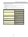
4-2 System Requirements
Windows
-Windows 98 (including SE)
-Windows 2000
-Windows Me
*Windows XP
Macintosh
-Mac OS from 8.6 to 9.2 (PS A100)
-Mac OS from 8.6 to 10.1 (PS A200) *
CPU
Pentium 150MHz and over
(XP requires 233MHz and over)
Power PC
Memory
(RAM)
-32MB or more (Win98)
-64MB or more (Win Me/2000)
-128MB or more (Win XP)
-ZoomBrowser EX 3.3 (PhotoRecord 1.4) :
120MB or more
-PhotoStitch 3.1 : 40MB or more
-Remotecapture 2.4 : 20MB or more
-Raw Image Converter 2.0 : 10MB or more
-USB TWAIN Driver 4.3 : 25MB or more
-USB WIA Driver 4.3 : 25MB or more
20MB or more for application
OS
Space capacity P
of hard disk
S
A
1
0
0
-CP-10 PrinterDriver : 1MB or more
*1: Capacity for
installation
P
S
A
2
0
0
-USB Mounter is available with Mac OS 9.0 to 9.2
*1
-ZoomBrowser EX 3.4 (PhotoRecord 1.4) :
120MB or more
-PhotoStitch 3.1 : 40MB or more
-RemoteCapture 2.5 : 20MB or more
-USB TWAIN Driver 4.5 : 25MB or more
-USB WIA Driver 4.5 : 25MB or more
-CP-10 PrinterDriver : 1MB or more
Display
* unavailable of Mac OS 10.0
* unavailable with Mac OS 10.1 at UFS (Unix File System)
*1
-ImageBrowser 2.3 : 20MB or more
-PhotoStitch 3.1 : 30MB or more
-Remotecapture 2.4 : 15MB or more
-Raw Image Converter 2.0 : 10MB or more
-USB Mounter 1.4 : 5MB or more
-USB Plug-In Module 4.3 : 15MB or more
*1
-CP-10 PrinterDriver : 3.8MB or more
-ImageBrowser 2.3 : 20MB or more
-PhotoStitch 3.1 : 30MB or more
-Remotecapture 2.5 : 15MB or more
-USB Mounter 1.6 : 5MB or more
-USB Plug-In Module 4.5 : 15MB or more
-CP-10 PrinterDriver : 3.8MB or more
*1
800 x 600 dots (256 color) or more
1,024 x 768 dots (32000 color) or more
(recommended)
800 x 600 dots (8 bits) and over
1,024 x 768 dots (16 bits) and over
(recommended)
* Solution Disk Ver. 9.0 is bundled with the PS A100
Solution Disk Ver. 10.0 is bundled with the PS A200
1-28
104 (16.2)
31.4(1.23)
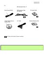
z Compact Power Adapter CA-PS800
• Rated input : 100 - 240 V AC (50/60 Hz)
16 VA (100 V) - 26 VA (240 V)
• Rated output: 3.15 V DC, 2 A
• Ambient temperature : 0 - 40 ºC
• Dimensions : 42.5 (1.67) X 104 (4.11) X 31.4 (1.27) mm (inch)
• Weight
: Approx. 180 g (Excluding cable)
42.6(1.68)
4-3 Specifications of Major Accessories
z Ni-MH Battery NB-1AH
• Type : Size-AA Ni-MH battery (rechargeable)
Unit:mm(inch)
• Voltage
: 1.2 V DC
Fig.4-1 Compact Power Adapter CA-PS800
• Capacity : 1600 mAH (1550 mAH : min.)
• Ambient temperature : 0 - 40 ºC
• Dimensions : Approx. 14.5 (0.57) dia. x 50 (1.97) mm (inch)
• Weight
: Approx. 27 (0.95 oz) g
z Battery Charger CB-3AH
• Rated input : 100 - 240 V AC (50/60 Hz)*, 8 W
• Rated output : Charging current 0.92 A (average for 1 or 2 batteries), 0.46 A (average for 3 or 4 batteries)
• Charging time : Approx. 110 min. for 1 or 2 batteries, approx. 220 min. for 3 or 4 batteries
• Charging indicator : During charging : Orange lamp blinks
Charging completed : Orange lamp lights
• Ambient temperature : 0 - 40 ºC (0 - 35 ºC recommended)
• Dimensions : Approx. 113 (4.45) x 74 (2.91) x 27.4 (1.08) mm (inch)
• Weight
: Approx. 100 (3.53) g (oz)
*In the US, it will be 120 VAC (60 Hz).
27.4(1.07)
Unit: mm(inch)
Fig.4-2 NiMH Battery NB-1AH
113.0 (44.48)
14.5
50.0 (1.96)
(0.57)
74.0 (2.91)
Fig.4-3 Battery Charger CB-3AH
1-29
Unit : mm (inch)
6.8(0.27)
z Interface Cable IFC-300PCU
• USB Series A 4-pin connector - Series mini - B 5-pin connector
• The dimensions are shown in Fig. 4-4.
15.8(0.62)
12.2(0.78)
38.5(1.52)
Fig. 4-4 Interface Cable IFC-300PCU
24.3
(0.96) 7.0
(0.27)
φ4.6
(0.18)
z Direct Interface Cable DIF-100
• Square type 10-pin connector - Round type 5-pin USB connector
• The dimensions are shown in Fig. 4-5.
60.0 (2.36)
40.0(1.57)
Fig. 4-5 Direct Interface Cable DIF-100
1-30
Unit : mm (inch)
5 System
5-1 Accessory compatibility
zPowerShot / IXY series accessory compatibility
<Battery>
NB-5H
NB-4H
NB-1L
BP-511
BP-512
NB4-100
NB-2L
PS A200
PS A100
PS A40
PS A30
PS S30
PS S40
PS G2
O*1
-
O
-
O
O
O
-
IXY D 200 IXY D 300
PS A20
PS A10
IXY
DIGITAL
PS Pro
90 IS
PS G1
PS S10
PS S20
PS Pro70
PS A5 Z
PS A50
PS A5
O
-
O
-
O
-
O
-
O
-
O
-
O
-
O
-
O
-
O
-
O
O
-
O
O
-
-(O)*2
O
O
-
O
O
O
-
O
O
-
O
O
-
O
-
O
-
O
-
O
-
* 1 2 sets of 2 batteries (4 battery package).
<Adapter/Charger>
CA-PS100/100E
CA-PS200
CA-PS300
CA-PS500
CA-560
CR-560
CA-PS800
CB-2L/2LE
CB-2LS/2LSE
CB-3AH
CBK100
CB-2LT/CB-2LTE
O
O*3
O*3
-
-(O)*2
O
O
-
O
O
O
-
* 2 It is possible to use by inserting the adapter's DC plug in the jack of PS A40/A30/A20/A10 cameras directly without using DC coupler.
* 3 4 batteries (2 set of 2) can be recharged.
<DC Coupler>
DR-100/100A
DR-200
DR-300
DR-500
DR-700
<Lens Accessory>
WC-DC58
WC-DC52
TC-DC58
250D 58mm
500D 58mm
250D 52mm
LA-DC58
LA-DC52
LH-DC58
TC-DC52
LA-DC52B
-
-
O
-
O
-
O
-
-
O
-
-
-
O
-
O
-
O
-
O
-
-
O
O
O
O
-
O
O
O
O
-
-
-
O
O
O
O
-
-
O
O
O
-
O
O
O
O
-
-
-
-
-
1-31
<Speed Lite>
220EX
380EX
550EX
420EX
(MR-14EX)
<Remote Sw itch>
WL-DC100
RS-8N3
<Cable, Others>
VC-100
VC-200
AVC-DC100
AVC-DC200
IFC-100PCS
IFC-100MC
IFC-200PCS
IFC-200PCU
IFC-200MC
IFC-300PCU
AD-PC98
DIF-100
DIF-200
-
-
-
O
O
O
O
O
-
-
-
-
O
O
O
O
-
O
O
O
O
-
-
O
O
-
-
-
-
-
-
O
-
-
-
-
-
O
-
O
-
-
O
-
-
O
O
-
O*4
O*6
O
O
-
O
O
O
-
O
O
O
-
O
O
O
O
O
O
-
O*5
O
O
-
O
O
-
O
O
O
O
O
-
O
O
O
O
O
-
O
O
O
O
O
-
O
O
O
O
-
O
O
O
O
-
O
O
O
O
-
* 4 PS A30 only
<Case>
SC-PS100
SC-PS300
SC-PS400
SC-PS500
SC-PS600
O
SC-PS700
SHC-PS200
SHC-PS300
SC-PS800
SC-PS900
O
<All Weather Case / Waterproof Case>
AW-PS100
AW-PS110
AW-PS200
WP-DC100
WP-DC200
WP-DC300
WP-DC200s
O
WP-DC400
O
-
* 5 PS A20 only
* 6 PS A40 only
O
O
O
-
O
-
O
-
O
-
O
-
O
-
O
-
O
-
O
-
O
-
O
-
O
-
-
O
-
O
-
O
O
-
O
-
-
-
-
-
O
-
O
-
1-32
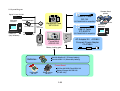
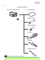
5-2 System Diagram
Camera direct
printer
Digital Printer CD-300
Macintosh
Windows
PCMCIA Adapter
PC Card Slot
(IXY D300/A20/A10 compatible) CP-10
Type I
CF Card
Waterproof Case
WP-DC400
USB I/F Cable
IFC-300PCU
CF Card Reader
Digital
git al
Digit
CF slot
(Type I)
Batteries :
DC
DC
PowerShot
A200/A100
Terminal
part
(IXY D300/A20/A10 compatible)
AC Adapter Kit ACK800
Compact Power Adapter
CA-PS800
Battery loading gate
Size-AA Alkaline X 2 (Primary battery)
Size-AA NiMH X 2 (Secondary battery)
Canon Brand
Size-AA NiMH
NB-1AH
Battery Charger
CB-3AH
4X Size-AA NiMH Pack NB4-100
Battery/Charger Kit CBK100
(4Z NB-1AH)
1-33
New
w
New
Windows/
Macintosh
CF OPEN
Parallel I/F
(Only Windows)
Direct I/F Cable
DIF-100
CP-100
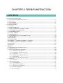
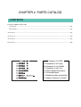
CHAPTER 2. TECHNICAL DESCRIPTION
CONTENTS
1. Functions of each unit
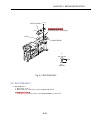
1.1 MAIN PCB ASS’Y --------------------------------------------------------------------------------------------------------- 2-1
1.2 FLASH UNIT ---------------------------------------------------------------------------------------------------------------- 2-1
2. Outline of Circuits
2.1 Power Supply Control ------------------------------------------------------------------------------------------------------ 2-2
2.1.1 Power Supply Block Diagram ----------------------------------------------------------------------------------- 2-2
2.1.2 Power Control Sequence ------------------------------------------------------------------------------------------ 2-2
2.2 Signal Processing ------------------------------------------------------------------------------------------------------------ 2-3
2.2.1 System Control ----------------------------------------------------------------------------------------------------- 2-3
2.2.2 Picture Processing ------------------------------------------------------------------------------------------------- 2-4
3. Troubleshooting
3.1 When an Error Code is Displayed ---------------------------------------------------------------------------------------- 2-5
3.2 When a Problem Occurs ---------------------------------------------------------------------------------------------------- 2-7
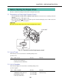
CHAPTER 2. TECHNICAL DESCRIPTION
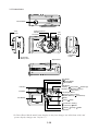
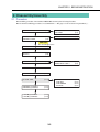
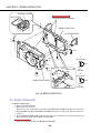
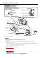
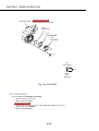
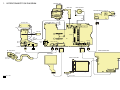
1. Functions of each unit
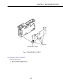
1.1 MAIN PCB ASS’Y
1)
2)
3)
4)
Driving the CCD Sensor.
Conversion of the image signal from the analog signal to the digital signal.
Controlling the power supply and the system by CPU. (Refer to Sections 2.1 and 2.2.)
Image processing, and reading and writing the image signal to and from the CF card using DSP.
(Refer to Section 2.2.2.)
5) LCD drive.
6) Power supply drive (DC/DC converter).
7) Backlight for LCD drive.
1.2 FLASH UNIT
1) Flash drive and charging circuit for the flash.
RLS PCB ASS’Y
MAIN PCB ASS’Y
FLASH UNIT
OPTICAL UNIT
Fig. 1
2-1
CHAPTER 2. TECHNICAL DESCRIPTION
2. Outline of Circuits
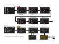
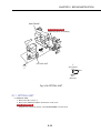
2.1 Power Supply Control
The power supply is controlled by the CPU mounted on the main PCB ass’y.
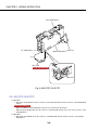
2.1.1 Power Supply Block Diagram
MAIN PCB ASS'Y
E1, E2, E3
CPU
BATTERY
or
DC_IN
VBATT
DC/DC
CONVERTER
E1
OUTPUT
FUSE
E2
OUTPUT
E3
OUTPUT
REG
(2.5V)
REG
(2.5V)
VCC1
(3.3V)
VCC1A
(3.3V)
VCC1M
(3.3V)
VDD2
(15V)
VEE2
(–7.5V)
VCC2
(4.2V)
VDD34
(13.5V)
VCC3
(4.2V)
REG
(3.0V)
for DSP
for System Control
for Motor Drive
for Image Process (CCD etc.)
for LCD
for System Control
VBATT
Fig. 2 Power System Block Diagram
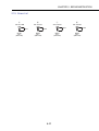
2.1.2 Power Control Sequence
"Battery is Installed" or "DC-IN"
Turn on the PLAY switch
Playback Mode
LCD ON
(E3)
Open the Barrier (E1)
Shooting Mode
LCD OFF
(E2)
2-2
LCD ON
(E2, E3)
CHAPTER 2. TECHNICAL DESCRIPTION
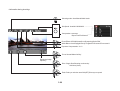
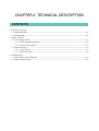
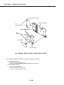
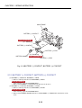
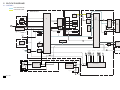
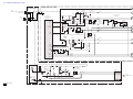
2.2 Signal Processing
MAIN PCB ASS'Y
SDRAM
CF card
HD, VD
CLK
Drive Pulse
TG
DSP
CCD
Sensor
LCD
Driver
CDS, A/D
LCD
Motor
Driver
EF LENS
AF Support LED
FLASH MEMORY
FINDER LED
USB
Buzzer
CPU
RTC
SW
KEY
Electric FLASH
Fig. 3 Signal System Block Diagram
2.2.1 System Control
The CPU on the main PCB ass’y controls the EF lens (motor, shutter), operation switch receiver, USB
communication and flowing circuits.
•
•
•
•
•
•
•
•
TG: Creation of the CCD drive pulse
CDS, A/D: CCD signal processing and conversion of the digital data
LCD Driver: Driving the LCD
FLASH MEMORY: Firmware memory
DSP: Picture processing
RTC: Clock count for watch
AF Support LED: AF auxiliary, self-timer and red-eye protection also serves as a lamp
Electric Flash: Flash and charging circuit
2-3
CHAPTER 2. TECHNICAL DESCRIPTION
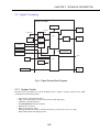
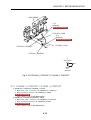
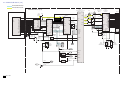
2.2.2 Picture Processing
1) The drive pulse of the CCD sensor is created by both clock from DSP and TG that is operated by
sync. signal.
The picture signal by the drive pulse is output from CCD sensor.
The output signal of the CCD picture is converted to the signal processing and the digital data by
the CDS and A/D converter, and is sent to the DSP.
2) The DSP circuit performs the following signal processing.
• Processes the picture data (using the SDRAM).
• Writes and reads the picture data to and from the CF card.
• Outputs analog video signal to the LCD.
3) The video signal that is supplied form the DSP is controlled by the LCD driver and is displayed
on the LCD.
2-4
CHAPTER 2. TECHNICAL DESCRIPTION
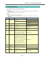
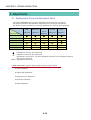
3. Troubleshooting
3.1 When an Error Code is Displayed
[Remedy]
• Check for any abnormalities in the mounting of probable faulty parts or connector connections referring
to the table below.
• Try replacing probable faulty parts referring to the below.
[NOTE]
• The error code is displayed on the LCD Monitor.
• Adjustments must be performed after the part has been replaced. For details, see the chapter of
“Adjustments”.
Error Code
E02
Name
Occurrence Conditions
Cause and Probable Faulty Part
AF
AF processing did not end within the
MAIN PCB ASS’Y
TIME OUT
specified time.
OPTICAL UNIT
The focus lens was not driven.
MAIN PCB ASS’Y
OPTICAL UNIT
E03
E09
E14
EF
Auto Flash Control did not end within the
MAIN PCB ASS’Y
TIME OUT
specified time.
OPTICAL UNIT
JPEG DMA
JPEG processing did not end within the
TIME OUT
specified time.
UNKOWN
When unkown error, cause of which is
MAIN PCB ASS’Y
UNKOWN
not known, occurs.
E16
IMAGING TIME
When communication between CPU and
OUT
peripheral IC is not completed within the
MAIN PCB ASS’Y
specified time during recording using
EVF or after completion of recording.
E23
CF NO SPACE
When the CF becomes full during writing
of photographed images to CF, writing is
repeatedly performed with the JPEG
compression ratio successively increased
to reduce the size of the image file until it
MAIN PCB ASS’Y
can be successfully written to CF.
This error occurs when writing of the
JPEG image file fails after 10 retries at
increasingly higher compression ratios.
E24
E25
E26
POWER ON
The power of the imaging circuit on the
ERROR
MAIN PCB ASS’Y was not detected.
FOCUS PI
Detection of the focus PI (photo-
OPTICAL UNIT
ERROR
interrupter) failed.
MAIN PCB ASS’Y
CAPTURE
Writing of the photograph image to
TIME OUT
SDRAM did not end within the specified
time.
2-5
MAIN PCB ASS’Y
MAIN PCB ASS’Y
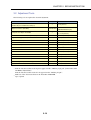
CHAPTER 2. TECHNICAL DESCRIPTION
Error Code
E27
Name
Occurrence Conditions
CF WRITE
Free area could not be secured in the
TIME OVER
buffer for the photograph image within
the specified time in the continuous
Cause and Probable Faulty Part
CF CARD
MAIN PCB ASS’Y
shooting mode.
E30
POWER OFF
The camera power was turned OFF while
The battery or DC plug was removed
ERROR
the image was being recorded to the CF
while the image was being recorded to
Card. (The error code is displayed when
the CF Card.
the camera is next turned ON.)
→ Remedy: Restart the camera.
* This error may occur after E23.
E50
E51
E52
CF FORMAT
The CF Card could not be formatted
ERROR
properly.
CF ACCESS
When image data cannot be read from
ERROR
CF normally.
QUICK REVIEW
Review of the photograph image failed.
ERROR
2-6
CF CARD
CF CARD
MAIN PCB ASS’Y
CHAPTER 2. TECHNICAL DESCRIPTION
3.2 When a Problem Occurs
[Remedy]
• Check for any abnormalities in the mounting of probable faulty parts or connector connections referring
to the table below.
• Try replacing probable faulty parts referring to the table below.
[NOTE]
• Adjustments must be performed after the part has been replaced. For details, see the chapter of
“Adjustments”.
Problem (when an error code is not displayed)
Cause and Probable Faulty Part
The camera does not work.
MAIN PCB ASS’Y
REAR COVER UNIT
FLASH UNIT
The image is not displayed on the LCD Monitor.
MAIN PCB ASS’Y
BUTTON PCB ASS’Y
LCD PANEL
BACK LIGHT UNIT
The photograph image is abnormal.
OPTICAL UNIT
MAIN PCB ASS’Y
The zoom does not function.
MAIN PCB ASS’Y
BATTERY BOX UNIT
REAR COVER UNIT
The Built-in Flash does not fire.
FLASH UNIT
MAIN PCB ASS’Y
Communications with the personal computer is not possible.
MAIN PCB ASS’Y
The CF card or Micro Drives is not recognized.
CF CARD
REAR COVER UNIT
MAIN PCB ASS’Y
Buttons/The Mode dial do not work.
REAR COVER UNIT
RLS PCB ASS’Y
2-7
CHAPTER 3. REPAIR INSTRUCTION
CONTENTS
1. Before Starting the Repair Work
1.1 Precaution on Flash High Tension Circuit ------------------------------------------------------------------------------- 3-1
1.2 List of Tools ----------------------------------------------------------------------------------------------------------------- 3-1
1.3 List of Supplies -------------------------------------------------------------------------------------------------------------- 3-1
1.4 Flexible Connectors --------------------------------------------------------------------------------------------------------- 3-2
2. Disassembly/Assembly
2.1 Procedure --------------------------------------------------------------------------------------------------------------------- 3-3
2.2 REAR COVER UNIT ------------------------------------------------------------------------------------------------------ 3-4
2.3 FRONT COVER UNIT, BATTERY COVER -------------------------------------------------------------------------- 3-5
2.4 BACKLIGHT UNIT, LCD PANEL -------------------------------------------------------------------------------------- 3-6
2.5 MAIN SHIELD CASE 2 --------------------------------------------------------------------------------------------------- 3-7
2.6 M-S FPC, M-R FPC -------------------------------------------------------------------------------------------------------- 3-8
2.7 MAIN PCB ASS’Y --------------------------------------------------------------------------------------------------------- 3-9
2.8 MAIN SHIELD CASE 3, MAIN SHIELD CASE 1 ------------------------------------------------------------------3-10
2.9 RLS PCB ASS’Y ---------------------------------------------------------------------------------------------------------- 3-11
2.10 FLASH UNIT ---------------------------------------------------------------------------------------------------------------3-12
2.11 OPTICAL UNIT ---------------------------------------------------------------------------------------------------------- 3-13
2.12 BATTERY (-) CONTACT, BATTERY (+) CONTACT -------------------------------------------------------------3-14
2.13 LITHIUM (-) CONTACT, LITHIUM (+) CONTACT ---------------------------------------------------------------3-15
2.14 CCD ASS’Y ----------------------------------------------------------------------------------------------------------------3-16
2.15 Screw List -------------------------------------------------------------------------------------------------------------------3-17
3. Adjustments
3.1 Replacement Parts and Adjustment Items ----------------------------------------------------------------------------- 3-18
3.2 Adjustment Tools ----------------------------------------------------------------------------------------------------------3-19
3.3 Before Starting Electrical Adjustments ---------------------------------------------------------------------------------3-20
3.3.1 TWAIN Driver Installation --------------------------------------------------------------------------------------3-20
3.3.2 Installing the Adjustment Software --------------------------------------------------------------------------- 3-20
3.3.3 Preparation -------------------------------------------------------------------------------------------------------- 3-22
3.3.4 Starting up the Adjustment Software ---------------------------------------------------------------------------3-23
3.3.5 Menu Window -----------------------------------------------------------------------------------------------------3-23
3.3.6 How to Use the Adjustment Software -------------------------------------------------------------------------3-23
3.4 Calibration ----------------------------------------------------------------------------------------------------------------- 3-24
3.4.1 Calibration -------------------------------------------------------------------------------------------------------- 3-24
3.5 Adjustment Procedure -----------------------------------------------------------------------------------------------------3-29
3.5.1 CCD Adjustment ------------------------------------------------------------------------------------------------- 3-29
3.5.2 Optical Unit Adjustment ---------------------------------------------------------------------------------------- 3-31
3.5.3 Imaging Process Adjustment ------------------------------------------------------------------------------------3-33
3.5.4 Pixel Dot Adjustment --------------------------------------------------------------------------------------------3-37
3.5.5 Flash Adjustment -------------------------------------------------------------------------------------------------3-39
CHAPTER 3. REPAIR INSTRUCTION
1. Before Starting the Repair Work
Be sure to read the following precaution before starting the repair work.
1.1 Precaution on Flash High Tension Circuit
•
•
When the FRONT COVER UNIT and REAR COVER UNIT are removed, be sure to discharge the main
capacitor.
(Discharging resistor : 1 kΩ, approx. 5 W.)
First contact the GND
terminal of the main capacitor with the discharging resistor. Then contact the
positive
terminal of the main capacitor.
CAUTION:
Be careful of electric shock because the circuit is the high tension circuit.
FLASH UNIT
+ terminal
(1k /5W)
– terminal
Fig. 3-1 Precaution on flash high tension circuit
1.2 List of Tools
The following tools are used for the re-assembling during service.
(1) List of tools
New
Name of tools
Screwdriver (Local Purchase)
Tweezers (Local Purchase)
Soldering iron (Local Purchase)
Part No.
Remarks
1.3 List of Supplies
The following supplies are used for the re-assembling during service.
(1) List of supplies
New
Name of supplies
ADHESIVE TAPE SONY T4000
ADHESIVE TAPE 3M No.56
DIA BOND No.1663G
Solder (Local Purchase)
Part No.
CY4-6012-000
CY4-6018-000
CY9-8129-000
3-1
Remarks
Double-sided Tape
Insulation Tape
CHAPTER 3. REPAIR INSTRUCTION
1.4 Flexible Connectors
This product uses the three types of the flexible connectors.
1 Type A
UNLOCK
LOCK
The contact-piece
should face
downwards
Unlocked state
Locked state
2 Type B
UNLOCK
LOCK
The contact-piece
should face
upwards
Unlocked state
Locked state
3 Type C
The contact-piece
should face
frontwards
Unconnected state
Connected state
Holes
Fig. 3-2 Flexible connectors
CAUTIONS:
1. For the connectors of Type A and Type B, set them to the unlocked
state before removing and inserting flexible card. After flexible card
is inserted, set them to the locked state.
2. The flexible card is equipped with the holes as shown. Use them for
removal and insertion by inserting the tweezers into them as required.
3-2
Fig. 3-3 Holes for removal
CHAPTER 3. REPAIR INSTRUCTION
2. Disassembly/Assembly
2.1 Procedure
Disassembling procedure of PowerShot A100/A200 is shown by the following flowchart.
Reverse the disassembling procedure to reassemble them. ∗ The pages to refer are shown in parenthesis ( ).
REAR COVER UNIT
(2-2)
BACKLIGHT UNIT
LCD PANEL
(2-4)
(2-4)
FRONT COVER UNIT
BATTERY COVER
(2-3)
(2-3)
BARRIER PANEL
(2-3)
MAIN SHIELD CASE 3
MAIN SHIELD CASE 1
(2-8)
(2-8)
CCD ASS'Y
CCD UNIT
CCD RUBBER
IR FILTER
(2-14)
(2-14)
(2-14)
(2-14)
CAUTION
Be careful high tension
MAIN SHIELD CASE 2
(2-5)
M-S FPC
M-R FPC
(2-6)
(2-6)
MAIN PCB ASS'Y
(2-7)
RLS PCB ASS'Y
(2-9)
FLASH UNIT
(2-10)
OPTICAL UNIT
(2-11)
BATTERY(-)CONTACT
BATTERY(+)CONTACT
(2-12)
(2-12)
LITHIUM(-)CONTACT
LITHIUM(+)CONTACT
(2-13)
(2-13)
3-3
CHAPTER 3. REPAIR INSTRUCTION
BATTERY COVER
NOTE (Assembling)
Positioning when assembling
SIDE COVER
(1)-3
b
(1)-3
REAR COVER UNIT
LITHIUM BATTERY
b
(1)-3
(1)-1
(1)-4
(1)-2
a
a
a
(1)-2
CD1-4157-000
4.0mm
(1)-2
a
(1)-2
a
(1)-2
LCD FPC
MO FPC
(1)-4
METAL
M1.7
REAR COVER (SELF TAP)
UNIT
b
XA4-9170-557
CONNECTOR COVER
5.5mm
METAL
M1.7
(SELF TAP)
Fig. 3-4 REAR COVER UNIT
2.2 REAR COVER UNIT
(1) REAR COVER UNIT
1. Remove the Lithium Battery.
2. Remove the four screws a.
Remove one screw among them by turning the CONNECTOR COVER in the direction of the arrow.
3. Open the SIDE COVER and BATTERY COVER in the direction of the arrow and remove the four
screws b.
4. Open the REAR COVER UNIT in the direction of the arrow and remove it by disconnecting the two
flexible printed wired boards (LCD FPC and MO FPC).
NOTE (Assembling)
Align the positioning dowel of the REAR COVER UNIT.
3-4
CHAPTER 3. REPAIR INSTRUCTION
(1)-2
(1)-2 BATTERY COVER
(1)-2
FRONT COVER UNIT
(1)-2
NOTE (Assembling)
(1)-3
BARRIER PANEL
BR FPC
(1)-1
Fig. 3-5 FRONT COVER UNIT, BATTERY COVER
2.3 FRONT COVER UNIT, BATTERY COVER
(1) FRONT COVER UNIT, BATTERY COVER
1. Disconnect the BR FPC.
2. Remove the FRONT COVER UNIT in the direction of the arrow. At the same time, remove the
BATTERY COVER in the direction of the arrow too.
3. Remove the BARRIER PANEL.
NOTE (Assembling)
When assembling, apply the DIA BOND1663G.
3-5
CHAPTER 3. REPAIR INSTRUCTION
REAR COVER UNIT
NOTE (Assembling)
Positioning when assembling
NOTE (Assembling)
(1)-1
Soldering
(2)-1
Claws
(2)-1
LCD PANEL
(1)-2
c
NOTE (Assembling)
(2)-1
Claws
(1)-2
c
c
(1)-3 BACKLIGHT UNIT
XA4-9170-407
4.0mm
METAL
M1.7
(SELF TAP)
Fig. 3-6 BACKLIGHT UNIT, LCD PANEL
2.4 BACKLIGHT UNIT, LCD PANEL
(1) BACKLIGHT UNIT
1. Remove soldering at three locations.
NOTE (Assembling)
After soldering, apply the DIA BOND1663G.
2. Remove the four screws c.
3. Remove the BACKLIGHT UNIT.
NOTE (Assembling)
Align the two positioning dowels of the REAR COVER UNIT at each location.
(2) LCD PANEL
1. Release the six claws in the top, bottom, right and left, and remove the BACKLIGHT UNIT and LCD
PANEL.
NOTE (Assembling)
The BACKLIGHT supplied as the service part had the protection sheet. Remove it.
3-6
CHAPTER 3. REPAIR INSTRUCTION
Soldering
MAIN SHIELD CASE 2
Fig. 3-7 MAIN SHIELD CASE 2
2.5 MAIN SHIELD CASE 2
(1) MAIN SHIELD CASE 2
1. Remove soldering at four locations.
2. Remove the MAIN SHIELD CASE 2.
3-7
CHAPTER 3. REPAIR INSTRUCTION
RLS PCB ASS'Y
(1)-2
(1)-2
ST PCB ASS'Y
MAIN PCB ASS'Y
(1)-1
M-R FPC
(1)-1
M-S FPC
NOTE (Assembling)
M-S FPC
Fig. 3-8 M-S FPC, M-R FPC
2.6 M-S FPC, M-R FPC
(1) M-S FPC
1. Disconnect the M-S FPC from the connector on the ST PCB ASS’Y and the connector of the MAIN PCB
ASS’Y.
NOTE (Assembling)
When assembling, fold the M-S FPC in trisection as shown in the illustration.
When inserting the M-S FPC into the connector on the ST PCB ASS’Y side, loosen the two screws of the
ST PCB ASS’Y.
(2) M-R FPC
1. Disconnect the M-R FPC from the connector of the RLS PCB ASS’Y and the connector of the MAIN
PCB ASS’Y.
3-8
CHAPTER 3. REPAIR INSTRUCTION
NOTE (Assembling)
Routing the LITHIUM LEAD
NOTE (Assembling)
Positioning when assembling
OPT FPC
OPTICAL UNIT
NOTE (Assembling)
LITHIUM LEAD
Red
(1)-2
Soldering
(1)-4
NOTE (Assembling)
Positioning when assembling
Soldering
(1)-3
Red
c
(1)-5
Black
CCD-UNIT
Black
FLASH cable
NOTE (Assembling)
c
(1)-1 Soldering (1)-5
(1)-6
MAIN PCB ASS'Y
c
XA4-9170-407
4.0mm
METAL
M1.7
(SELF TAP)
Fig. 3-9 MAIN PCB ASS’Y
2.7 MAIN PCB ASS’Y
(1) MAIN PCB ASS’Y
1. Remove soldering at sixteen locations where the CCD-UNIT pins are fixed.
2. Remove soldering at two locations and remove the two LITHIUM LEADs (red and black).
NOTE (Assembling)
After soldering, apply the DIA BOND1663G.
For routing the LITHIUM LEADs, pass them between MAIN FRAME and OPTICAL UNIT.
3. Remove soldering at two locations and remove the two FLASH cables (red and black).
NOTE (Assembling)
After soldering, apply the DIA BOND1663G.
4. Disconnect the OPT FPC from the connector of the MAIN PCB ASS’Y.
5. Remove the four screws c.
6. Remove the MAIN PCB ASS’Y.
NOTE (Assembling)
Align the two positioning dowels of the MAIN FRAME at each location.
3-9
CHAPTER 3. REPAIR INSTRUCTION
MAIN SHIELD CASE 3
MAIN PCB ASS'Y
(1)-1
Soldering
(1)-2
MAIN SHIELD CASE 1
(2)-2
Soldering
EM1 SHEET
(2)-1
(2)-2 Soldering
Fig. 3-10 MAIN SHIELD CASE 3, MAIN SHIELD CASE 1
2.8 MAIN SHIELD CASE 3, MAIN SHIELD CASE 1
(1) MAIN SHIELD CASE 3
1. Remove soldering at two locations.
2. Remove the MAIN SHIELD CASE 3 in the direction of the arrow.
(2) MAIN SHIELD CASE 1
1. Remove the EM1 SHEET.
2. Remove soldering at four locations.
3. Remove the MAIN SHIELD CASE 1.
3-10
CHAPTER 3. REPAIR INSTRUCTION
(1)-1
RLS PCB ASS'Y
c
NOTE (Assembling)
Positioning when assembling
(1)-2
Claws
MAIN FRAME
c
XA4-9170-407
4.0mm
METAL
M1.7
(SELF TAP)
Fig. 3-11 RLS PCB ASS’Y
2.9 RLS PCB ASS’Y
(1) RLS PCB ASS’Y
1. Remove the screw c.
2. While taking care of the claws, remove the RLS PCB ASS’Y.
NOTE (Assembling)
Align the two positioning dowels of the MAIN FRAME at each location.
3-11
CHAPTER 3. REPAIR INSTRUCTION
CAUTION : Discharge of Capasitor
Do not touch the terminals of the
discharging capasitor.Be sure to discharge
the main capasitor with a discharge resistor.
(1 k ohms, approx.5 W)
NOTE (Assembling)
OPTICAL UNIT
MAIN FRAME
terminal
BATTERY LEAD
Orange
(2)-2
MICROPHONE LEAD
Gray
(1k
/5W)
Recessed portion of
the MAIN FRAME
– terminal
Claws
Recessed portion of the MAIN FRAME
ELECT CAPASITOR
(2)-3
(2)-1
NOTE (Assembling)
Soldering
Black
BATTERY
LEAD
Orange
Gray
Gray
Black
Orange
Red
(2)-2
MICROPHONE
LEAD
(1)-3
Mold part
(1)-4
c
XA4-9170-407
Red
4.0mm
(2)-1 Soldering
(1)-2
(1)-1 Soldering c
NOTE (Assembling)
FLASH UNIT
METAL
M1.7
(SELF TAP)
Fig. 3-12 FLASH UNIT
2.10 FLASH UNIT
CAUTION
Be sure to discharge the main capacitor with a discharging resistor.
(1) FLASH UNIT
1. Remove soldering at two locations and remove the two BATTERY LEADs (red and black).
2. Remove the two screws c.
3. Insert the sharp point tweezers between the mold part of the FLASH UNIT and MAIN FRAME and
remove the mold part of the FLASH UNIT from the dowel.
4. Remove the FLASH UNIT in the direction of the arrow.
(2) ELECT CAPACITOR
1. Remove soldering at four locations.
NOTE (Assembling)
After soldering, apply the DIA BOND1663G.
2. Remove the two MICROPHONE LEADs (gray and orange).
NOTE (Assembling)
Route the MICROPHONE LEAD through the recessed portion of the MAIN FRAME and route it under
the BATTERY LAED.
3. While taking care of the claws, remove the ELECT CAPACITOR.
3-12
CHAPTER 3. REPAIR INSTRUCTION
MAIN FRAME
NOTE (Assembling)
Positioning when assembling
(1)-2
OPTICAL UNIT
(1)-1
c
c
XA4-9170-407
4.0mm
METAL
M1.7
(SELF TAP)
Fig. 3-13 OPTICAL UNIT
2.11 OPTICAL UNIT
(1) OPTICAL UNIT
1. Remove the three screws c.
2. Remove the OPTICAL UNIT in the direction of the arrow.
NOTE (Assembling)
Align the two positioning dowels of the MAIN FRAME at each location.
3-13
CHAPTER 3. REPAIR INSTRUCTION
MAIN FRAME
BATTERY (-) CONTACT
(1)-2
NOTE (Assembling)
(1)-1 Soldering
BATTERY (+) CONTACT
(2)-2
BATTERY (-) LEAD
BATTERY GUARD
(2)-1 Soldering
NOTE (Assembling)
BATTERY (+) LEAD
Fig. 3-14 BATTERY (-) CONTACT, BATTERY (+) CONTACT
2.12 BATTERY (-) CONTACT, BATTERY (+) CONTACT
(1) BATTERY (-) CONTACT, BATTERY (-) LEAD
1. Remove soldering and remove the BATTERY (-) LEAD.
NOTE (Assembling)
After soldering, apply the DIA BOND1663G.
2. Remove the BATTERY (-) CONTACT in the direction of the arrow.
(2) BATTERY (+) CONTACT, BATTERY (+) LEAD
1. Remove soldering and remove the BATTERY (+) LEAD.
NOTE (Assembling)
After soldering, apply the DIA BOND1663G.
2. Remove the BATTERY GUARD and remove the BATTERY (+) CONTACT in the direction of the
arrow.
3-14
CHAPTER 3. REPAIR INSTRUCTION
MAIN FRAME
(1)-2
Soldering
NOTE (Assembling)
LITHIUM (+) LEAD
(2)-2
Soldering
NOTE (Assembling)
(1)-1
c
(2)-1
c
LITHIUM (+) CONTACT
LITHIUM (-) LEAD
LITHIUM (-) CONTACT
c
XA4-9170-407
4.0mm
METAL
M1.7
(SELF TAP)
Fig. 3-15 LITHIUM (+) CONTACT, LITHIUM (-) CONTACT
2.13 LITHIUM (+) CONTACT, LITHIUM (-) CONTACT
(1) LITHIUM (+) CONTACT, LITHIUM (+) LEAD
1. Remove the screw c and remove the LITHIUM (+) CONTACT.
2. Remove soldering and remove the LITHIUM (+) LEAD.
NOTE (Assembling)
After soldering, apply the DIA BOND1663G.
(2) LITHIUM (-) CONTACT, LITHIUM (-) LEAD
1. Remove the screw c and remove the LITHIUM (-) CONTACT.
2. Remove soldering and remove the LITHIUM (-) LEAD.
NOTE (Assembling)
After soldering, apply the DIA BOND1663G.
3-15
CHAPTER 3. REPAIR INSTRUCTION
OPTICAL UNIT
NOTE (Assembling)
Positioning when assembling
(1)-4
IR FILTER
(1)-3
CCD RUBBER
(1)-2
CCD UNIT
(1)-1
d
d
XA4-9140-307
3.0mm
METAL
M1.4
(SELF TAP)
Fig. 3-16 CCD ASS’Y
2.14 CCD ASS’Y
(1) CCD UNIT, CCD RUBBER, IR FILTER
1. Remove the three screws d.
2. Remove the CCD UNIT.
NOTE (Assembling)
Align the two positioning dowels of the OPTICAL UNIT at each location.
3. Remove the CCD RUBBER.
4. Remove the IR FILTER.
3-16
CHAPTER 3. REPAIR INSTRUCTION
2.15 Screw List
a
b
c
d
CD1-4157-000
XA4-9170-557
XA4-9170-407
XA4-9140-307
METAL
M1.7
(SELF TAP)
4.0mm
5.5mm
4.0mm
METAL
M1.7
(SELF TAP)
METAL
M1.7
(SELF TAP)
3-17
3.0mm
METAL
M1.4
(SELF TAP)
CHAPTER 3. REPAIR INSTRUCTION
3. Adjustments
3.1 Replacement Parts and Adjustment Items
PowerShot A100/A200 requires electrical adjustments when certain parts are replaced.
The table below indicates the adjustments required for the respective part replacements.
For all other parts not listed below, no electrical adjustments are necessary after replacement.
Adjustment Items
CCD
Adjustment
Optical Unit
Adjustment
Replacement Part
CCD UNIT
Imaging
Process
Pixel Dot
Flash
Adjustment
Adjustment
Adjustment
#1
#2
#3
#4
#5
OPTICAL UNIT
FLASH UNIT
MAIN PCB ASS’Y
LCD PANEL
BACK LIGHT UNIT
: Adjustment is necessary after replacement.
: Adjustment is necessary after replacement.
(Adjustment is not necessary, only if the adjustment data has been saved and then transferred
after the part is replaced.)
Blank : Adjustment is unnecessary.
∗ When CCD UNIT is replaced, adjust certainly at the procedure as below.
#1. CCD Adjustment
#2. Optical Unit Adjustment
#3. Imaging Process Adjustment
#4. Pixel Dot Adjustment
#5. Flash Adjustment
3-18
CHAPTER 3. REPAIR INSTRUCTION
3.2 Adjustment Tools
The following tools are required for electrical adjustment.
DESCRIPTION
PARTS NO.
PC/AT-Compatible Machine
(Windows98 pre-installed Model, USB port)
—
Adjustment Software (CD-ROM)
CY8-4377-031
REMARKS
Local purchase
CD-ROM,
SERVICE MANUAL (J/E)
Compact Power Adapter CA-PS800
—
Enclosed in camera kit
(or Local purchase)
INTERFACE CABLE IFC-300PCU (USB Cable)
—
(or Local purchase)
Brightness Box (light source A)
—
Local purchase
Color Viewer (5600° K)
DY9-2039-100
(or Local purchase)
Standard Color Bar Chart
DY9-2002-000
(or Local purchase)
Standard 18% Gray Chart
CY4-6016-000
CHART, 18%GRAY
AF Chart
—
*1
W-10 Filter *2
CY9-1543-000
(or Local purchase)
C-12 Filter
DY9-2029-000
(or Local purchase)
ND-2 Filter
—
Local purchase
ND-4 Filter
—
Local purchase
ND-8 Filter
—
Local purchase
Light-Shielding Cloth (500 × 500 or larger)
—
Local purchase
Tripod
—
Local purchase
*1
Print the Auto Focus Chart on the legal size paper from the “AFChart_Legal.pdf ” (in the folder of this
CD-ROM, :\Adjust\Chart).
Print the Auto Focus Chart on the A3 size paper from the “AFChart_A3.pdf ”.
Make use of the Auto Focus Chart for the PowerShot A100/A200.
*2
2pcs. required.
3-19
CHAPTER 3. REPAIR INSTRUCTION
3.3 Before Starting Electrical Adjustments
3.3.1
TWAIN Driver Installation
Install the USB Driver for Adjustment in the CD-ROM to PC.
(“This Adjustment Software” is impossible when the RS-232C TWAIN driver is used.)
3.3.2
Installing the Adjustment Software
1. Double click the icon on the launcher screen or a file in the CD-ROM. (Model name of the camera
that you are going to adjust and the name of the adjustment software are different.)
Camera Type
Power Shot A100
Power Shot A200
A30, A40, A100&A200
Icon
File Path
A100_ENG_Adj.
A200_ENG_Adj.
Font Set
\Adjust\A100\Eng\Setup.exe
\Adjust\A200\Eng\Setup.exe
\Adjust\Font Set\Setup.exe
2. When the dialog box below appears, click the “OK” button.
3-20
CHAPTER 3. REPAIR INSTRUCTION
3. When the dialog box below appears, click the
button. (Software installation will then begin.)
4. When the dialog box below appears, click the “Continue” button.
(In the case that you do not add a shortcut on desktop, remove clicking from the check box.)
3-21
CHAPTER 3. REPAIR INSTRUCTION
3.3.3
Preparation
Before starting up the Adjustment Software, follow the preparatory steps below:
1. Obtain all the tools necessary for the adjustment.
2. Connect the Camera to the Power Source with the Compact Power Adapter CA-PS800.
3. Set the Replay Mode on the camera and turn on.
Personal Computer
USB
INTERFACE CABLE
IFC-300PCU
CAMERA BODY
DIGITAL
Compact Power Adapter
CA-PS800
4. Connect the Camera’s Digital terminal to the PC’s USB Port with INTERFACE CABLE IFC-300
PCU.
5. Turn on the camera.
Note: Perform the preparation in the following order otherwise the camera won’t work properly.
3-22
CHAPTER 3. REPAIR INSTRUCTION
3.3.4
Starting up the Adjustment Software
After completing the preparatory steps, click Start and move the cursor to Program; then select Canon
Digital Camera and click PowerShot A100/A200 Adjustment.
3.3.5
Menu Window
When the Adjustment Software starts up, the Menu Window below will appear.
3.3.6
How to Use the Adjustment Software
Calibration/Adjustment
For starting, click the button related with adjustment.
* Whenever you use your light source for the adjustment for the first time, be sure to click the “Calibration” Button.
Quitting the Adjustment Software
Click the “Exit” button.
Saving or Loading data
• “Save” button : This button saves all adjustment data stored on the camera in text format.
• “Load” button : This button loads all adjustment data saved in text format to the camera.
Saving or Loading data
• “Save” button : This button saves all adjustment data stored on the camera in text format.
• “Load” button : This button loads all adjustment data saved in text format to the camera.
Notes
• If the adjustment fails, a message indicating the failure will appear on each product. If this happens,
do the adjustment again.
• The Adjustment Software is dedicated only to Canon Digital Camera PowerShot A100/A200.
Never use it for any other camera.
• The Windows98 must be pre-installed on the computer that is equipped with the USB terminal.
(Windows95 does not support the USB.)
* The operation with the Win2000, WinMe, etc. is not guaranteed.
3-23
CHAPTER 3. REPAIR INSTRUCTION
3.4 Calibration
3.4.1
Calibration
■ Tools Used
• Reference Camera (Merchandise)
• Compact Power Adapter CA-PS800
• Adjustment Software
• INTERFACE CABLE IFC-300PCU
• Personal Computer
• Color Viewer (5600° K)
• C-12 Filter
1
Click the “Calibration” button.
2
1. When the message on the right appears, check
that the reference camera (Merchandise) is connected to the computer.
2. Click the “OK” button.
3
When the message on the right appears, go to 4.
3-24
• ND-8 Filter
• ND-2 or ND-4 Filter
• W-10 Filter (2pcs.)
CHAPTER 3. REPAIR INSTRUCTION
4
1. Place the camera so that lens is set against the
light source surface of the Brightness Box via
the C-12 Filter.
2. Set the Brightness Box to EV12.
3. Click the “Check” button.
4. Check the Brightness level if it is within
0 ± 5.
* If not, calibrate the Brightness Box until it
becomes within 0 ± 5.
5. Click the “NEXT” button.
5
1. When the message on the right appears, Set the
Brightness Box to EV15 and attach the ND-8
Filter while setting the C-12 Filter between the
lens.
2. Click the “Check” button.
3. Check the Brightness level if it is within
0 ± 5.
* If not, calibrate the Brightness Box until it
becomes within 0 ± 5.
4. Click the “NEXT” button.
6
When the message on the right appears go to 7.
7
1. Attach the ND Filter* between the Lens and
the Color Viewer.
2. Place the camera so that the lens is set against
the center part of the Color Viewer.
3. Click the “ADJUST” button.
C-12 Filter
Brightness
Box
CAMERA
BODY
Power
Source
Personal
Computer
Color Viewer
ND-4 or ND-2
Filter
CAMERA
BODY
Power
Source
* PowerShot A100 : ND-4
PowerShot A200 : ND-2
Stand
Personal
Computer
3-25
CHAPTER 3. REPAIR INSTRUCTION
8
When the message on the right appears go to 9.
9
1. Remove the ND Filter.
2. Attach the two W-10 Filters between the Lens
and the Color Viewer.
Place the camera so that the lens is set against
the center part of the Color Viewer.
3. Click the “ADJUST” button.
Color Viewer
W-10
Filter
CAMERA
BODY
Power
Source
Stand
Personal
Computer
10
When the message on the right appears go to 11.
11
1. Remove the two W-10 Filters.
2. Attach the C-12 Filter between the Lens and
the Color Viewer.
Place the camera so that the lens is set against
the center part of the Color Viewer.
3. Click the “ADJUST” button.
Color Viewer
C-12
Filter
CAMERA
BODY
Power
Source
Stand
Personal
Computer
3-26
CHAPTER 3. REPAIR INSTRUCTION
12
When the message on the right appears go to 13.
13
1. Attach the Color Bar Chart to the Color Viewer.
2. Place the camera so that the Viewing image of
the color bar chart is the full of LCD with the
ND Filter* attached.
3. Click the “ADJUST” button.
Color Viewer
Color Bar Chart
ND-4 or ND-2
Filter
CAMERA
BODY
* PowerShot A100 : ND-4
PowerShot A200 : ND-2
Power
Source
Personal
Computer
14
1. Shift a black frame on the displayed screen with
a mouse to choose a color of color bar.
2. Click the “Sampling” button.
15
Check “Save as Reference”, and click the “OK”
button to store the data.
3-27
Stand
CHAPTER 3. REPAIR INSTRUCTION
16
When the message on the right appears, click the
“FINISH” button.
(This ends the “Calibration”.)
3-28
CHAPTER 3. REPAIR INSTRUCTION
3.5 Adjustment Procedure
3.5.1
CCD Adjustment
■ Tools Used
• Personal Computer
• INTERFACE CABLE IFC-300PCU
• Brightness Box (light source A)
• Adjustment Software
• Compact Power Adapter CA-PS800
• C-12 Filter
1
Click the “CCD” button.
2
When the message on the right appears, go to 3.
3
1. Place the camera so that lens is set against the
light source surface of the Brightness Box via
the C-12 Filter.
2. Set the Brightness Box to EV12.
3. Click the “ADJUST” button.
C-12 Filter
Brightness
Box
CAMERA
BODY
Power
Source
Personal
Computer
3-29
CHAPTER 3. REPAIR INSTRUCTION
4
When the message on the right appears, Set the
Brightness Box to EV15 while setting the C-12
Filter between the lens.
Click the “ADJUST” button.
5
When the message on the right appears, click the
“FINISH” button.
(This ends the “CCD” Adjustment.)
3-30
CHAPTER 3. REPAIR INSTRUCTION
3.5.2
Optical Unit Adjustment
■ Tools Used
• Personal Computer
• INTERFACE CABLE IFC-300PCU
• AF Chart
• Tripod
• Adjustment Software
• Compact Power Adapter CA-PS800
1
Click the “Optical Unit” button.
2
When the message on the right appears, go to 3.
3
1. Place the AF Chart at 52.0cm away from the
front of the camera finder.
* Place the Auto Focus Chart on a plain color
wall or equivalent.
* Adjust the light so that the brightness of the
chart will be about EV8.5.
2. Adjust the position of the camera finely so that
the center of the Auto Focus Chart is aligned
with the center of the LCD.
3. Click the “ADJUST” button.
3-31
AF CHART
52.0cm
Power
Source
Personal
Computer
CAMERA
BODY
Tripod
CHAPTER 3. REPAIR INSTRUCTION
4
When the message on the right appears, click the
“FINISH” button.
(This ends the “Optical Unit” Adjustment.)
3-32
CHAPTER 3. REPAIR INSTRUCTION
3.5.3
Imaging Process Adjustment
■ Tools Used
• Personal Computer
• INTERFACE CABLE IFC-300PCU
• Brightness Box (light source A)
• Compact Power Adapter CA-PS800
• Color Viewer (5600° K)
• Adjustment Software
• W-10 Filter (2 pcs.)
1
Click the “Imaging Process” button.
2
When the message on the right appears, go to 3.
3
1. Attach the ND Filter* between the Lens and
the Color Viewer.
2. Place the camera so that the lens is set against
the center part of the Color Viewer.
3. Click the “ADJUST” button.
Color Viewer
• Color Bar Chart
• ND-2 or ND-4 Filter
• C-12 Filter
ND-4 or ND-2
Filter
CAMERA
BODY
Power
Source
* PowerShot A100 : ND-4
PowerShot A200 : ND-2
Stand
Personal
Computer
3-33
CHAPTER 3. REPAIR INSTRUCTION
4
When the message on the right appears, go to 5.
5
1. Remove the ND Filter.
2. Attach the two W-10 Filters.
Place the camera so that the lens is set against
the center part of the Color Viewer.
3. Click the “ADJUST” button.
Color Viewer
W-10
Filter
CAMERA
BODY
Power
Source
Stand
Personal
Computer
6
When the message on the right appears, go to 7.
7
1. Remove the two W-10 Filters.
2. Attach the C-12 Filter.
Place the camera so that the lens is set against
the center part of the Color Viewer.
3. Click the “ADJUST” button.
Color Viewer
C-12
Filter
CAMERA
BODY
Power
Source
Stand
Personal
Computer
3-34
CHAPTER 3. REPAIR INSTRUCTION
8
When the message on the right appears, go to 9.
9
1. Attach the Color Bar Chart to the Color Viewer.
2. Place the camera so that the viewing image of
the color bar chart is the full of LCD with the
ND Filter* attached.
3. Click the “ADJUST” button.
Color Viewer
Color Bar Chart
ND-4 or ND-2
Filter
CAMERA
BODY
* PowerShot A100 : ND-4
PowerShot A200 : ND-2
Power
Source
Personal
Computer
10
1. Shift a black frame on the displayed screen with
a mouse to choose a color of color bar.
3. Click the “Sampling” button.
11
Check “Yellow and Red”, and click the “OK”
button.
If these data are within specifications, go to 13.
* Specification
Ave_Cr = Reference Camera ± 10
Ave_Cb = Reference Camera ± 10
3-35
Stand
CHAPTER 3. REPAIR INSTRUCTION
12
1. Confirm to see that the image on the PC monitor satisfies the specifications.
2. If the image on the PC monitor does not satisfy
the specifications, change the data using UP,
DOWN button or change the data directly by
typing the data in the text box. Then click the
“UPDATE” button.
13
When the adjustment is completed, click the
“FINISH” button.
(This ends the “Imaging Process” Adjustment.)
3-36
CHAPTER 3. REPAIR INSTRUCTION
3.5.4
Pixel Dot Adjustment
■ Tools Used
• Personal Computer
• INTERFACE CABLE IFC-300PCU
• Brightness Box (light source A)
• Color Viewer (5600° K)
• Compact Power Adapter CA-PS800
• Adjustment Software
• C-12 Filter
• Light-Shielding Cloth (500 × 500 or larger)
1
Click the “Pixel Dot” button.
2
When the message on the right appears, go to 3.
3
1. Place the camera so that lens is set against the
light source surface of the Brightness Box via
the C-12 Filter.
2. Set the Brightness Box to EV12.
3. Click the “ADJUST” button.
C-12 Filter
Brightness
Box
CAMERA
BODY
Power
Source
Personal
Computer
3-37
CHAPTER 3. REPAIR INSTRUCTION
4
1. When the message on the right appears, cover
the camera with the Light-Shielding Cloth so
that the no light reasons the CCD.
2. Click the “ADJUST” button.
5
When the message on the right appears, click the
“FINISH” button.
(This ends the “Pixel Dot” Adjustment.)
3-38
CHAPTER 3. REPAIR INSTRUCTION
3.5.5
Flash Adjustment
■ Tools Used
• Personal Computer
• INTERFACE CABLE IFC-300PCU
• Compact Power Adapter CA-PS800
• Adjustment Software
1
Click the “Flash” button.
2
When the message on the right appears, go to 3.
3
1. Set 18% Gray Chart 60cm from the Finder
front.
2. Make the room as dark as a darkroom.
3. Click the “ADJUST” button.
• 18% Gray Chart
• Tripod
18% Gray Chart
60cm
Power
Source
CAMERA
BODY
Personal
Computer
3-39
Tripod
CHAPTER 3. REPAIR INSTRUCTION
4
When the message on the right appears, click the
“FINISH” button.
(This ends the “Flash” Adjustment.)
3-40
CHAPTER 3. REPAIR INSTRUCTION
3.5.6
Language (For Oth)
■ Tools Used
• Personal Computer
• INTERFACE CABLE IFC-300PCU
• Compact Power Adapter CA-PS800
• Adjustment Software (FontSet.exe)
1
Open the “FontSet.exe”
and click the “New Connection” button.
2
When the message on the right appears, confirm
the model name, and click the “OK” button.
3
When the message on the right appears,
click the “Oth” button.
3-41
CHAPTER 3. REPAIR INSTRUCTION
4
*Make sure to appear “err:0 on the bottom line.
3-42
CHAPTER 4. PARTS CATALOG
CONTENTS
PowerShot A200/PowerShot A100
Casing Parts ----------------------------------------------------------------------------------------------------------------------- Pg1
Internal Parts ---------------------------------------------------------------------------------------------------------------------- Pg2
Accessories-1 ------------------------------------------------------------------------------------------------------------------------- Pg3
Accessories-2 ------------------------------------------------------------------------------------------------------------------------- Pg4
Accessories-3 ------------------------------------------------------------------------------------------------------------------------- Pg5
Service Tools -------------------------------------------------------------------------------------------------------------------------- Pg6
Category of CLASS
A: Frequency of use: High
B: Frequency of use: Middle
C: Frequency of use: Low
D: Safety-related critical parts
E: Consumable parts
F: Standard screws and washers
S: Supply of the parts is limited
PowerShot A200
PowerShot A100
Casing Parts
Pg1
16
8
c
12
a
d
10
15
11
N.S
9
17
13
b
5
17
c
e
7
16
2
a
6
b
e
1
3
d
15
18
4
14
15
15
PowerShot A200
PowerShot A100
Pg1
PARTS LIST
SYMBOL
PARTS NO.
CLASS QTY
DESCRIPTION
REMARKS
1
CM1-1307-000
CM1-1440-000
B
B
1
1
FRONT COVER UNIT
FRONT COVER UNIT
A100
A200
2
3
CD1-4159-000
CB1-8303-000
B
B
1
1
CUSHION, BATTERY COVER
PLATE, LOGO
4
CD1-4324-000
B
1
PANEL, BARRIER
5
6
CD1-4126-000
CD1-4121-000
B
C
1
1
COVER, CF
PLATE, BATTERY CONTACT
7
8
CD1-4124-000
CD1-4127-000
B
B
1
1
COVER, BATTERY
COVER, SIDE
9
CD1-4128-000
C
1
BAR, BATTERY COVER
10
CK5-0051-000
CK5-0051-001
C
C
1
1
PANEL, LCD
PANEL, LCD (SELECTION)
11
12
CM1-1310-000
CD1-4138-000
C
B
1
1
BACK LIGHT UNIT
HOLDER, LITHIUM BATTERY
13
CM1-1308-000
B
1
REAR COVER UNIT
14
CY1-6158-000
CY1-6159-000
CY1-6160-000
B
B
B
1
1
1
PLATE, BODY NUMBER (J)
PLATE, BODY NUMBER (N)
PLATE, BODY NUMBER (E)
A100
A100
A100
CY1-6161-000
CY1-6181-000
B
B
1
1
PLATE, BODY NUMBER (O)
PLATE, BODY NUMBER (J)
A100
A200
CY1-6182-000
B
1
PLATE, BODY NUMBER (N)
A200
CY1-6183-000
CY1-6184-000
B
B
1
1
PLATE, BODY NUMBER (E)
PLATE, BODY NUMBER (O)
A200
A200
15
16
CD1-4157-000
XA4-9170-557
F
F
4
4
SCREW
SCREW
17
XA4-9170-407
F
4
SCREW
18
CD1-4118-000
B
1
COVER, CONNECTOR
PowerShot A200
PowerShot A100
Pg2
Internal Parts
25
26
29
28
24
27
23
29
a
22
15
29
16
21
29
9
17
29
13
18
11
12
14
19
10
29
2
3
a
4
20
30
5
6
29
31
8
32
1
29
7
29
PowerShot A200
PowerShot A100
Pg2
PARTS LIST
SYMBOL
PARTS NO.
CLASS QTY
DESCRIPTION
REMARKS
1
2
CY1-6156-000
YN1-1936-000
B
C
1
1
OPTICAL UNIT
FILTER, IR
YN1-1937-000
CD1-4087-000
C
C
1
1
FILTER, IR
RUBBER, CCD
A200
3
4
CY1-6157-000
C
1
CCD UNIT
A100
C
C
1
1
CCD UNIT
LEAD, MICROPHONE (-)
A200
5
CY1-6180-000
CK2-1269-000
6
7
CK2-1268-000
CM1-1305-000
C
C
1
1
LEAD, MICROPHONE (+)
FLASH UNIT
8
CK2-1270-000
C
1
FPC, M-S
9
10
CD1-4120-000
CK2-1271-000
C
C
1
1
CONTACT, BATTERY (-)
LEAD, BATTERY (+)
11
12
CD1-4119-000
CD1-4122-000
C
C
1
1
CONTACT, BATTERY (+)
GUARD, BATTERY (+)
13
CK2-1272-000
C
1
LEAD, BATTERY (-)
14
15
16
CK9-0402-000
CM1-1302-000
CD1-4125-000
C
C
C
1
1
1
CAPASITOR, ELECT., 80µ/330V
PCB ASS’Y, RLS
PLATE, BATTERY LOCK
17
CK2-1290-000
C
1
LEAD, LITHIUM (+)
18
19
CD1-4139-000
CK2-1291-000
C
C
1
1
CONTACT, LITHIUM (+)
LEAD, LITHIUM (-)
20
21
CD1-4140-000
CD1-4113-000
C
C
1
1
CONTACT, LITHIUM (-)
FRAME, MAIN
22
CD1-4418-000
C
1
SHEET, EM 1
23
24
CD1-4141-000
CD1-4143-000
C
C
1
1
CASE, MAIN SHIELD 1
CASE, MAIN SHIELD 3
25
26
CK2-1257-000
CD1-4142-000
C
C
1
1
FPC, M-R
CASE, MAIN SHIELD 2
27
CD1-4419-000
C
1
SHEET, EM 2
28
CM1-1301-000
CM1-1439-000
C
C
1
1
PCB ASS’Y, MAIN
PCB ASS’Y, MAIN
29
30
XA4-9170-407
XA4-9140-307
F
F
13
3
SCREW
SCREW
31
CK9-0416-000
C
1
FUSE, SKK UMF 2012
32
CK9-0415-000
C
1
FUSE, SKK I14
A100
A100
A200
PowerShot A200
PowerShot A100
Pg3
Accessories-1
Wrist Strap WS-200
USB Interface Cable
IFC-300PCU
CF Card FC-8M
1
N.S
Canon Digital Camera
Solution Disk
2
AC Cable
N.S
Alkaline Batteries (X2)
3
N.S
N.Sl : N.S Stand for No Stock (Product available)
PowerShot A200
PowerShot A100
Pg3
PARTS LIST
SYMBOL
1
2
3
PARTS NO.
CLASS QTY
DESCRIPTION
REMARKS
C84-1060-000
C84-1115-000
B
S
1
1
WRIST STRAP WS-200
CD-ROM, SOLUTION DISK VER.9.0 (J/E) PS A100
C84-1116-000
S
1
AUSTRALIA
CD-ROM, SOLUTION DISK VER.9.0 (E/F/S) PS A100 FOR USA, CANADA
C84-1117-000
S
1
CD-ROM, SOLUTION DISK VER.10.0 (J/E) PS A200
C84-1118-000
S
1
CD-ROM, SOLUTION DISK VER.10.0 (E/F/S) PS A200 FOR USA, CANADA
WT3-5062-000
WT3-5063-000
C
C
1
1
AC CABLE (J)
AC CABLE (N)
FOR JAPAN
FOR USA, CANADA
WT3-5064-000
WT3-5115-000
C
C
1
1
AC CABLE (E)
AC CABLE (B)
FOR EUROPE, ASIA
FOR USA
WT3-5066-000
C
1
AC CABLE (A)
FOR AUSTRALIA
FOR JAPAN, ASIA,
FOR JAPAN, ASIA,
AUSTRALIA
PowerShot A200
PowerShot A100
Pg4
Accessories-2
Water proof Case WP-DC400
Water proof Seal
1
N.S
Grease Packing
2
Protector Moisture
3
Neck Strap
4
Wrist Strap
5
Diffusion Plate Unit
6
N.Sl : N.S Stand for No Stock (Product available)
PowerShot A200
PowerShot A100
Pg4
PARTS LIST
SYMBOL
PARTS NO.
CLASS QTY
DESCRIPTION
1
2
CY1-6175-000
DY9-3029-000
B
C
1
1
PACKING, RUBBER, WP-DC400
GREASE, PACKING
3
4
DY9-3028-000
CY1-6099-000
C
B
1
1
PROTECTOR, MOISTURE
NECK STRAP
5
CY1-6174-000
B
1
WRIST STRAP
6
CY1-6176-000
B
1
DIFFUSION PLATE UNIT
REMARKS
PowerShot A200
PowerShot A100
Pg5
Accessories-3
Camera User Guide
1
Software Starter Guide
2
System Map
3
PowerShot A200
PowerShot A100
Pg5
PARTS LIST
SYMBOL
1
PARTS NO.
CLASS QTY
DESCRIPTION
REMARKS
CDI-J036-000
CDI-E037-000
S
S
1
1
I.BOOK (J) PS A100
I.BOOK (E) PS A100
FOR JAPAN
FOR USA, CANADA, ASIA,
CDI-F027-000
S
1
I.BOOK (F) PS A100
FOR CANADA
CDI-S034-000
S
1
I.BOOK (S) PS A100
FOR USA
CDI-J038-000
CDI-E039-000
S
S
1
1
I.BOOK (J) PS A200
I.BOOK (E) PS A200
FOR JAPAN
FOR USA, CANADA, ASIA,
CDI-F029-000
S
1
I.BOOK (F) PS A200
FOR CANADA
CDI-S036-000
S
1
I.BOOK (S) PS A200
FOR USA
CDI-J035-000
CDI-E045-000
S
S
1
1
SOFTWARE GUIDE (J) PS A100
SOFTWARE GUIDE (E) PS A100
FOR JAPAN
FOR USA, CANADA, ASIA,
AUSTRALIA
AUSTRALIA
2
AUSTRALIA
3
CDI-F035-000
S
1
SOFTWARE GUIDE (F) PS A100
FOR CANADA
CDI-S032-000
S
1
SOFTWARE GUIDE (S) PS A100
FOR USA
CDI-J042-000
CDI-E046-000
S
S
1
1
SOFTWARE GUIDE (J) PS A200
SOFTWARE GUIDE (E) PS A200
FOR JAPAN
FOR USA, CANADA, ASIA,
AUSTRALIA
CDI-F036-000
CDI-S033-000
S
S
1
1
SOFTWARE GUIDE (F) PS A200
SOFTWARE GUIDE (S) PS A200
FOR CANADA
FOR USA
CDI-J037-000
S
1
SYSTEM MAP (J) PS A100
FOR JAPAN
CDI-E038-000
S
1
SYSTEM MAP (E) PS A100
FOR USA, CANADA, ASIA,
AUSTRALIA
CDI-F028-000
CDI-S035-000
S
S
1
1
SYSTEM MAP (F) PS A100
SYSTEM MAP (S) PS A100
FOR CANADA
FOR USA
CDI-J039-000
S
1
SYSTEM MAP (J) PS A200
FOR JAPAN
CDI-E040-000
S
1
SYSTEM MAP (E) PS A200
FOR USA, CANADA, ASIA,
AUSTRALIA
CDI-F030-000
CDI-S037-000
S
S
1
1
SYSTEM MAP (F) PS A200
SYSTEM MAP (S) PS A200
FOR CANADA
FOR USA
PowerShot A200
PowerShot A100
Pg6
S e rv i c e T o o l s
DIA BOND NO.1663G BLACK
W-10 Filter
5
1
Adhesive Tape SONY T4000
18% Gray Chart
2
6
Adhesive Tape 3M NO.56
SERVICE MANUAL CD-ROM
3
7
C-12 Filter
4
PowerShot A200
PowerShot A100
Pg6
PARTS LIST
SYMBOL
PARTS NO.
CLASS QTY
DESCRIPTION
1
2
CY9-8129-000
CY9-6012-000
Y
Y
1
1
BOND, DIA BOND NO.1663G BLACK
ADHESIVE TAPE, SONY T4000
3
4
CY4-6018-000
DY9-2029-000
Y
Y
1
1
ADHESIVE TAPE, 3M NO.56
FILTER, C-12
5
CY9-1543-000
Y
1
FILTER, W-10
6
7
CY4-6016-000
CY8-4377-031
Y
Y
1
1
CHART, 18% GRAY
CD-ROM, SERVICE MANUAL (J/E)
REMARKS
6mm X 50m roll
15mm X 66m roll
CHAPTER 5. DIAGRAMS
CONTENTS
1. INTERCONNECTION DIAGRAM
2. BLOCK DIAGRAMS
2-1. OVERALL
2-2. MAIN PCB ASS’Y (1/4)
2-3. MAIN PCB ASS’Y (2/4)
2-4. MAIN PCB ASS’Y (3/4)
2-5. MAIN PCB ASS’Y (4/4)
2-6. Abbreviation in Block Diagrams
3. P.C.B. DIAGRAMS
3-1. MAIN PCB ASS’Y
3-2. FLASH UNIT
3-3. OPR PCB ASS’Y
3-4. RLS PCB ASS’Y
3-5. BL FPC ASS’Y
1. INTERCONNECTION DIAGRAM
OPTICAL UNIT
DATE BATTERY
OPT FPC
(–)
(+)
RLS PCB ASS’Y
Release SW
SW302
SW301
CCD
SENSOR
CN301
1
6
CF/Battery Cover
Detect SW
RED
BLK
MAIN PCB ASS'Y
FLASH, LED
RED
–
+
BLK
BRN
11
GRY
WHT
1
CN1701
1
BLK
GRY
CAPCITOR
ORG
BLUE
CN1009
RED
BLK
CN101
DC IN
1
FLASH UNIT
CN1702 CN1008
USB
50
1
FU101
CN1003
1
6
6
Barrier close
Detect SW
CN1011
23
1
5
6
CN1502
6
BLK
24
1
RED
BATTERY
BL FPC ASS’Y
Barrier open
Detect SW
5
6
FU102
3
CN104 1
CN1503
2
REAR COVER UNIT
LCD PANEL
BACK LIGHT UNIT
RED
BLK
BUZZER
1
23
CN201
01 June, 2002
(Direct solder)
C CANON INC., 2002
CONNECTORS
MAIN PCB ASS’Y
REAR COVER UNIT
CN1003
01 June, 2002
CN1009
CN1011
CN1503
FLASH UNIT
CN201
RLS PCB UNIT
CN101
CN301
1
M_GND
1
GND
1
VCC3
1
VBUS
1
VCC3
1
BATT+
1
M_GND
2
VBAT_TMP
2
D03
2
LED_BL
2
D-
2
LED_BL
2
SW
2
VBATT_TEMP
3
CFQP
3
D04
3
VCC1
3
D+
3
VCC1
3
GND
3
CFOP
4
SW2
4
D05
4
LED_MACRO
4
Not Connected
4
LED_MACRO
CN104
4
SW2
5
SW1
5
D06
5
LED_GREEN
5
UV_GND
5
LED_GREEN
1
GND
5
SW1
6
SCAN
6
D07
6
LED_ORANGE
CN1701
6
LED_ORANGE
2
EFCHG
6
SCAN
CN1008
7
/CE1
7
M_GND
1
AFA+
7
M_GND
3
GND
1
M_GND
8
A10
8
M_GND
2
AFB-
8
M_GND
4
STSP
2
BRCL
9
/CE1
9
SCAN
3
AFA-
9
SCAN
5
VCHGVL
3
SCAN
10
A09
10
ERASE
4
AFB+
10
ERASE
6
LED_SELF
4
BROP
11
A08
11
MENU
5
AFRST_COM
11
MENU
5
VBATT_R
12
A07
12
DSIP
6
AFRST_CO
12
DISP
6
M_GND
13
VCC
13
LEFT
7
AFRST_AN
13
LEFT
14
A06
14
DOWN
8
IR+
14
DOWN
15
A05
15
SET
9
IR-
15
SET
16
A04
16
RIGHT
10
SH+
16
RIGHT
17
A03
17
UP
11
SH-
17
UP
18
A02
18
WIDE
CN1702
18
WIDE
19
A01
19
TELE
GND
19
TELE
20
A00
20
PLAY
2
EFCHG
20
PLAY
21
D00
21
VBATT
3
GND
21
VBATT
22
D01
22
BUZZER
4
STSP
22
BUZZER
23
D02
23
C_GND
5
VCHGVL
23
C_GND
24
/IOIS15
CN1502
6
LED_SELF
25
/CD2
1
TESTL
26
/CD1
2
COM
27
D11
3
VST
28
D12
4
VCK
29
D13
5
EN
30
D14
6
DWN
31
D15
7
VDD
32
/CE2
8
VSS
33
/VS1
9
VDDG
34
/IORD
10
VSSG
35
/IOWR
11
Not Connected
36
/WE
12
WIDE
37
IREQ
13
HST
38
VCC
14
REF
39
Not Connected
15
Not Connected
40
/VS2
16
CEXT/REXT
41
RESET
17
HCK2
42
/WAIT
18
HCK1
43
Not Connected
19
PSIG
44
/REG
20
GREEN
45
Not Connected
21
RED
46
Not Connected
22
BLUE
47
D08
23
RGT
48
D09
24
Not Connected
49
D110
50
GND
1
C CANON INC., 2002
2. BLOCK DIAGRAMS
2.1 OVERALL
DATA COMMUNICATION
ANALOG IMAGE SIGNAL
OPTICAL UNIT
MAIN PCB ASS’Y
CCD
Sensor
CDS, A/D
RLS PCB ASS'Y
CPU
TH
OPT FPC
Digital
Signal
Processing
IC
CPU
Motor Driver
Release Switch
CF Open Switch
T.G
IRIS Motor
VCC1M
LCD
Driver
SHUTER Motor
LCD
PANEL
AF Motor
REAR COVER UNIT (1/3)
Buzzer
SDRAM
KEY Switch
FINDER LED
VCC1
REAR
COVER
UNIT(3/3)
RTC
VCC1
RESET
VDD3
DATE
BATTERY
OSC_N
FLASH MEMORY
Barrier
Open/Close
Switch
VBATT
VCC1
CF Card
BATTERY
Load Test
FRONT COVER UNIT
FLASH
for CCD
for LCD
BACK LIGHT
UNIT
FLASH UNIT
HV/OSC/XE_Drive
AF Support
LED
SELF
Red Eye
for Motor
VDD3
for System
Control
VCC1M
USB
Control
VCC 1
VCC 1A
VCC3
CN1503
VBATT
USB
VDD2
VCC 2
VEE 2
REAR COVER
UNIT (2/3)
DC/DC CONVERTER
BATTERY BOX UNIT
DC_IN
01 June, 2002
C CANON INC., 2002
2.2 MAIN PCB ASS’Y (1/4)
DATA COMMUNICATION
ANALOG IMAGE SIGNAL
MAIN PCB ASS’Y (1/4)
IC1011 (1/3)
Digital Signal Processing IC
MB87J8070PBT2-G
VCC1A_3
AVD
OPTICAL UNIT
Q1301
BUFFER
2SC4627J
C1317
OS
16
IC1304 TG
LR38575
IC1303 TG LR36685
CCD
Sensor
V1A
V1B
V2
V3A
V3B
V4
OFD
H2
H1
RS
OOFD
OD
PW
GND
14
13
12
11
10
9
3
8
7
5
6
1
10
9
4
8
7
5
1
V1X
VH1AX
V2X
V3X
VH3AX
V4X
VH1BX
VH3BX
OFDX
VL VH,VFOCH VDO
V1A
V1B
V2
V3A
V3B
V4
POFD
20
19
21
18
15
14
13
23
22
2
3
5
8
9
11
4
10
VEE2
IC1302 CDS,A/D
VSP2260Y
30
PBLK
19
13
YOUT1
CCDIN
AD_D0
ı
AD_D9
18
FCOS
19
FS
16
ADCK
32
HD
29
VD
25
CKI
27
CLK
A200 Model
B0
ı
B9
PBLK
10
Q1309
SWITCH
HN1804FU-GR
3 VCC-AD
28
CO8
4
21
SHP
22
SHD
16
ADCCK
CLP0B2 20
CLPOB
TG_HD
TG_VD
TG_CK
TG_MCK
C1512 22
Q1013
2SA1774
A100 Model
C1513 23
2
CCD2
ı
CCD11
Q1011
2SA1774
3
5
Q1512
HN2A01FU-GR
EX0
EX1
EX13
SCLK3
SDATA3
LCD_CS
47
CLP0B2
TG_HD
TG_VD
TG_CK
TG_MCK
SDATA
48
SCLK
46
SLOAD
AVDD,DVDD
Q1304
SWITCH
2SC4617
SSGOUT5
SSGOUT0
SSGOUT1
TGCLKO
CCDCLK
G/Y
R/R-Y
VST
VSK
EN
DWN
WIDE
HST
HCK1
HCK2
RGT
B/B-Y
25
SYNC_IN
32
SCK
33
SDAT
31
SEN
VCC1A_3
VDD3
Q1508
REG.
2SC4617
CN1502
10
R_OUT
12
G_OUT
8
B_OUT
6
COM
27
REF
6
COUT2
2
C1511 24
1
P4L_2
IC1502
LCD CONTROL
CXA3572R
4
RBOUT3
Q1012
2SA1774
6
35 SDATA2
ED2
34 SCLK2
ED1
33 TG_CS AD_LD
ED0
VDD4 1,2
VDD1-3
Q1308
VSUB CONT
DTC144EE
VDD2
Q1305
SWITCH
2SC4617
V1X
VH1AX
V2X
V3X
VH3AX
V4X
VH1BX
VH3BX
43
FH2
41
FH1
46
FR
1
OFDC
4
2
15
Q1507
2SA1774
SSGOUT4
VDD2
Q1011-Q1013
Q1507,Q1512
BUFFER
PSIGOUT
VCC1
VDD1,2 VCC2
3
2
1
47
46
44
42
43
40
RED
GREEN
BLUE
COM
REF
21
20
22
2
14
VST
VCK
EN
DWN
WIDE
HST
HCK1
HCK2
RGT
3
4
5
6
12
13
18
17
23
VDDG
9
19
LCD PANEL
14
PSTG
Q1509
REG.
2SC4617
SSGOUT3
6
P3_0
2
4
1
Q1302
SWITCH
UFM5N
5
4
1
5
SDATA2
SCLK2
6
EX10
EX9
TG_CS
AD_LD
Q1514
BUFFER
HN1804FU-GR
TG_HD
EX11
EX12
3
2
Q1515
BUFFER
HN1804FU-GR
6
1
4
5
3
VCC2
VCC2_AD
VCC1
VDDH1-20
VCC1A
IC1014
5 +2.5V REG 4
MM1385NN
IC1006
5 +3.0V REG 4
MM1385HN
AVD
AVD1-3
VREF1-3
VCC1A_3
VDDL1-8
A2LAT
LED_BL
01 June, 2002
2
EX36
VDD
1
VOUT
IC1016
2.5V REG
R1130H251B
P3_4
Q1010 LED Drive
2SC4617
C CANON INC., 2002
2.3 MAIN PCB ASS’Y (2/4)
DATA COMMUNICATION
ANALOG IMAGE SIGNAL
IC1001 (2/2) CPU
µPD82434S1-023-6C
TCTL0
MAIN PCB ASS’Y (2/4)
CN1503
D_P
2 D1 VBUS
3
Q1008
SWITCH
RN47A3
3
2
4
USB_VBUS
Q1009
SWITCH
RN47A3
2
1
Q1003 SWITCH
RN47A3
3
4
4
Q10002
2SD1664
2
EX39
1
TOUT3
EX6
INTP0
IC1002
VCC1
DATE
BATTERY
+
2
RESET
S-80927ANMP
INTP2
1
DQ0
ı
DQ15
16
11
/WE
26
/CE
28
/OE
WE
OE
TG_CS
AD_LD
LCD_CS
EX11
EX12
EX13
VCC
CLK
DATA
6
7
EX62
EX61
CF_IREQ
EX11
EX12
EX13
8
9
IRIS
Motor
IN3
IN4
12
OUT3
10
OUT4
SH +
SH -
10
11
SHUTTER
Motor
AFA +
1
AFA -
3
AFB +
4
AFB -
2
LB1836ML
IC1703 AF Motor Drive
OUT1
VCC
OUT2
5
OUT3
IN1
2
IN2
OUT4
3
ENA
LB1848M
EX68
EX57
EX56
8
7
9
10
A+
A–
B+
B–
AFRST_AN 7
AFRST_CO 6
AF
Motor
AF PI
AFRST_CA 5
2
Q1703
SWITCH
RN47A3
1
4
EX60
CS2
32KIN
VDD 1-24
AVDD
AVREF
EX47
CPUAD_0
ı
CPUAD_15
EX7
AVREFP
WE
OE
TRST
TMS
TCK
TDO
INTP1
WAITB
CSENGB
UBEB
ALE
EX42
ECLK
ESDT
ESREQ
VCC1A-3
CPUADR_0
ı
CPUADR_3
8
CPURDWR
CPUMEMIO
TRST
TMS
TCK
TDI
INTR
NWAIT
NCSE
P3_1
UBEB
AIN 4
AIN 5
AIN 6
AIN 7
5
6
7
3
2
1
VCC1
2
1
IC1010
AND GATE
TC7SH08FU
4
CN1702
LED_SELF
EFCHG
VCHGLVL
STSP
6
2
5
4
To FLASH UNIT
EFCHGC
IC1701
Comparator
NJM12903R
ALE
NRESET
BUSCLK
ESDT
ESREQ
AIN 1
Q1704
LED Drive
RN47A3
Q1703
SWITCH
RN47A3
VCC1
EX35
EX63
EXPORT
VCC_CF
IR +
IR -
1
IC1011 (2/3)
Digital Signal Processing IC
MB87J8070PBT2-G
INTP2
NAIB
PLL_AVDD
IOCHRDY
AIN6
13
9
3
OUT1
5
OUT2
VCC1
LIVDD
VCC2_AD
VCC 3
VBAT TEMP
6
CN1701
VCC,VS1
IN1
IN2
3
EX4
EX5
VCC 1
VCC 1A
VCC 1A_3
IC1702 IRIS/Shutter Drive
1,4
2
EX2
ı
EX68
RESETB
IC1007 Real Time Clock
RTC-4574JE
8
CE1
2
FOUT
3
CE0
1
EX14
EX15
EX40
Q1001
RN47A3
1
MRWB
CSMEMB
MRDB
VCC1M
ADIN_0
3
2
OPT FPC
A0
ı
A19
20
D0
ı
D15
EX41
VBATT
A1
ı
A20
1
BATTERY LOAD
TEST
OPTICAL UNIT
D_N
VCC1
4
EX0
EX1
EX9
EX10
IC1005
FLASH PROM
MBM29LV800BA-90PFTN
L1504
3 D+
USB
TG_HD
SCLK3
SDATA3
SCLK2
SDATA2
EX0
EX1
EX9
EX10
VDD2
1
2
4
IC1704
AND GATE
TC7SET08U
CXIN
OSC1_X1
OSC1_X2
X1001
24MHz
IC1003
AND GATE
TC7SH08FU
2
4
1
E1LAT
E2LAT
E3LAT
EX35
EX36
EX37
EX36
EX37
VCHGLVL
01 June, 2002
C CANON INC., 2002
2.4 MAIN PCB ASS’Y (3/4)
MAIN PCB ASS’Y (3/4)
DATA COMMUNICATION
IC1011 (3/3)
Digital Signal Processing IC
MB87J8070PBT2-G
IC1012
16M SDRAM
HY57V653220BTC-10
RLS PCB ASS'Y
CN1003
CN301
TH301
BATTERY Temp. Detect
VBATT_TEMP 6
AIN 6
2 VBATT_TEMP
A0
ı
A11
EXPORT
SW301
Release
SW1
SW2
SW1 5
SW2 4
SCAN 6
5 SW1
4 SW2
6 SCAN
CFOP 3
3 CFOP
EX25
EX24
DQ0
ı
DQ31
EX26
SW302
CF Open
CN201
YELLOW
GREEN
ORANGE
ERASE Button
MENU Button
DISP Button
LEFT Button
DOWN Button
SET Button
RIGHT Button
UP Button
WIDE Button
TELE Button
PLAY Button
CN1011
VCC1
LED_MACRO
LED_GREEN
LED_ORANGE
3
4
5
6
3
4
5
6
SCON
SCAN
ERASE
MENU
DISP
LEFT
DOWN
SET
RIGHT
UP
WIDE
TELE
PLAY
VBATT
9
10
11
12
13
14
15
16
17
18
19
20
21
9
10
11
12
13
14
15
16
17
18
19
20
21
SCAN
ERASE
MENU
DISP
LEFT
DOWN
SET
RIGHT
UP
WIDE
TELE
PLAY
VBATT
BUZZER 22
Q1004
LED/SWITCH Drive
RN1964
4
3
2
6
5
1
DIAL1
22 BUZZER
VCC3 1
LED_BL 2
1
2
VCC3
LED_BL
EX52
EX17
EX51
EX20
EX19
EX16
EX17
EX18
EX23
EX22
4
2
6
Q1007
LED Drive
RN1964
Q1020
Level Shift
RN47A3
Barrier Open
BR FPC
CN1008
2
3
4
5
BRCL
VBATT_R
VDD1-4
VDDQ1-8
32
SDDT_0
ı
SDDT_31
4
SDDQM_0
ı
SDDQM_3
EX 2
EX55
SDWE
SDCAS
SDRAS
SDCS_0
SDCLK
SDCKE
NXIN
5
NXOUT
P3_3
P3_2
3
3
4
1
VCC_CF
4
Q1005
Level Shift
RN47A3
P1_0
ı
P1_7
CF_A_3-10
3
8
4
1,2
5,6
PCDT_0
ı
PCDT_15
CF_D_0-15
16
INTP 2
NPCRD
NPCWR
PCCE1
PCCE2
PCRDY
PCIRQ
PCIOIS
P0-5
P0-1
P0-0
P0-4
EX28
EX29
EX30
EX31
CN1009
AD0
20
19
AD2
18
17
AD3
16
15
14
12
11
10
AD10
8
21
D00
22
23
2
3
4
5
6
47
48
49
27
28
29
30
D15
31
/IORQ 34
/IOWR 35
7
/CE1
32
/CE2
/WAIT 42
37
IREQ
/IOIS15 24
36
/WE
RESET 41
44
/REG
9
/CE
33
/VS1
40
/VS2
26
/CD1
/CD2
25
13
VCC
38
CF Card
3
EX53
LED_BL
17
/WE
18
/CAS
19
/RAS
20
/CS
68
CLK
67
CKE
X1002
14.31818MHz
3
2
1
Q1015
CF POWER SW
SI3445DV
Q1017,Q1016
DTC144EE
EX54
Q1016-Q1018
CF POWER CONT
SCAN
BROP
VCC1
VBATT
EX43
01 June, 2002
SDBS_O
SDBS_1
1
2
OPR PCB
UNIT
Barrier Close
DQM0
ı
DQM3
VCC1
VCC3
BACK LIGHT UNIT
2
CF_A_0-2
EX45
EX44
REAR COVER UNIT
Buzzer
BA0
BA1
12
SDADR_0
ı
SDADR_11
PCADR_0
ı
PCADR_2
Q1018
2SC4617
EX28-31
EX35
EIPLAT
FRONT COVER
UNIT
C CANON INC., 2002
2.5 MAIN PCB ASS’Y (4/4)
MAIN PCB UNIT (4/4)
FLASH UNIT
VBATT
Q1906
VDD2 REG
2SC4617
FU101
D1903
1
2
C1907
2SC4617
T1902
IC1901
SW REG CONTROL
LA5679T
L1907
IN2-
VCC
1
Q1904
PWM SW
MCH3406
36
6,29
OUT3
IN3-
DTC2
VREF
L1908
Q1905,Q1908
VEE2 REG
Q1905
DTC144EE
D1907
5
L1909
Q1908
2SA1774
D1902
4
5.6
S
G
D
3
Q1911
RN47A3
Q1913
2SK3019
Q1912
DTC144EE
VEE2
C1937
L1910
VCC1
L1911
1.2
VCC1A
L1912
VCC1M
Q1909
REG
SI34450V
18
C1922
IN1+
VCC1A_3
VCC2
D1904
3
12
Q1903
PWM SW
CPH3106
OUT1
Q1911,Q1912,Q1913
SWICH
Q107
2SC4617
6
7
C1923
VBIA51.2
Q1902
PWM SW
CPH3206
7
4
28
3 T1901 5
D1906
2
4
7
6
D1905
1
8
35
Q1916,Q1915
2SC4617
4
32
Q1910
PWM SW
DTC144EE
L1905
VDD3
L1906
VCC3
C1930
C1933
OUT2
8
2
C1927
C1928
1
3
2
1
C1924
CN101
DC_IN
Q1907
VCC1A-3 REG
VDD2
C1934
From
BATTERY CONTACT
DTC1,3
STBY3
STBY2
STBY1
FLASH
17
2
E1P LAT
E2 LAT
33
E3 LAT
D104
D103
Q104
XE Drive
CY20AAJ-B
Q102
EF Charge
2SB1197K
1
F
4
FU102
CN104
3
T102
LED
EX37
T101 2
5
AF Support
SELF
Red Eye
EIPLAT
EX36
Q203
OSC
2SC4672
EFCHG
Q101 SW
DTC144EE
STSP
EFCHG
VCHGLVL
From
MAIN PCB ASS’Y
VCHGLVL
STSP
LED_SFLF
01 June, 2002
3
5
2
1
C CANON INC., 2002
2.6 Abbreviation in Block Diagrams
Abbreviation
Nominal name
ADC
Analog-to-Digital (A/D) Converter
AE
Automatic Exposure control
AF
Automatic Focussing control
AND
Logic AND circuit
R-Y/B-Y
Description
Color difference signals of TV system
BPF
Band-Pass Filter
BUFFER
Buffer circuit
C
Chrominance signal
Color component signal of TV system
CCD
Charge-Coupled Device
CCD imager
CDS
Correlated Double Sampling system
COMP.VIDEO
Composite video signal
COMPARATOR
Voltage comparator
CPU
Central Processing Unit
DAC
Digital-to-Analog (D/A) Converter
DRAM
Dynamic Random Access Memory
Memory with which read and write are freely possible.
DSP
Digital Signal Processing
Typically DSP device
EEPROM
Electrically Erasable PROM
PROM that is electrically erasable.
EVF
Electronic View Finder
FET
Field Effect Transistor
FLASH MEMORY
Non-volatile memory with which write and read are freely
possible.
HPF
High-Pass Filter
I/F
InterFace
The circuit that interconnects 2 devices or circuits.
IGBT
Insulated Gate Bipolar Transistor
Conductivity-modulation type FET transistor
INV.
Logic Inverter circuit
IR
InfraRed ray
IRIS
Iris
LCD
Liquid Crystal Device
Typically LCD display
LED
Light Emitting Diode
Typically LED display
LPF
Low-Pass Filter
NTSC
National Television System Committees
OP Amp
OPerational Amplifier
OR
Logic OR circuit
OSC
OSCillator
PAL
Phase Alternating by Line
PLL
Phase Locked Loop
PROM
Programmable Read Only Memory
PWM
Pulse Width Modulation
REG.
REGulated power supply
NTSC color TV system developed in USA
PAL color TV system developed in Germany
Non-volatile memory in which program can be written.
RTC
Real Time Clock
Reference clock oscillator
SDRAM
Synchronous Dynamic RAM
DRAM whose bus interface is synchronous.
SECAM
SEquential Colour À Mémoire
SECAM color TV system developed in France
SW REG
SWitching REGulator
Switching type regulated power supply device
TG
Timing Generator
USB
Universal Serial Bus
VCO
Voltage Controlled Oscillator
VCXO
Voltage Controlled X’tal Oscillator
XE
Xenon Tube
Y
Y-signal
USB type serial data communication system
Luminance component signal of TV system
3. P.C.B. DIAGRAMS
3.1 MAIN PCB ASS’Y
MAIN PCB ASS’Y (SOLDERING SIDE)
01 June, 2002
MAIN PCB ASS’Y (COMPONENT SIDE)
C CANON INC., 2002
3.2 FLASH UNIT
FLASH PCB ASS’Y (SOLDERING SIDE)
01 June, 2002
FLASH PCB ASS’Y (COMPONENT SIDE)
C CANON INC., 2002
3.3 OPR PCB ASS’Y
01 June, 2002
C CANON INC., 2002
3.4 RLS PCB ASS’Y
01 June, 2002
C CANON INC., 2002
3.5 BL FPC ASS’Y
01 June, 2002
C CANON INC., 2002
How to print out the AF Chart
The large materials such as “AF Chart” that occupy a page of large size, can be divided into several
smaller pages using “Graphic Select Tool” for printing the entire page.
< Procedures >
1. Select “
Text Select Tool” from the Command Bar and keep pressing it.
Then, select the “
Graphic Select Tool”.
2. Select the desired portion to print. (Drag the cursor on desired area.)
3. Click “Print” of the Menu Bar. Check “Selected Thumbnails/Graphic”, then start printing.
When you check “Fit to Page”, the date can be reduced or enlarged of its printing size so that the
printing size fits the size of paper.*
4. To cancel the printing area, click an arbitrary position on the display.
* Remarks
The “AF Chart” of the Service Manual that is saved in this CD-ROM, has the colored markings in
colors so that the entire page can be divided into print papers (legal-size x 4 pages, A3 size x 3 pages).
Operate as follows.
Select “Graphic Select Tool”. Select the 2 markings having the same color to select the first printing
area. Press “Print” to print the first printing area. Perform the above steps 2 and 3. Select another 2
markings having the second color to select the second printing area. Press “Print” to print the second
printing area. Repeat this procedure until the all pages are printed.
<Legal-size>
<A3 size>
: Markings
PowerShot A100 / A200 AF Chart
PowerShot A100/A200 AF Chart
Dimensions
467.83mm
96.94mm
346.98mm
260.0mm
93.00mm
370.89mm