1
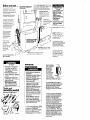
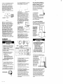
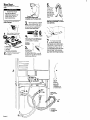
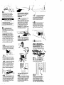
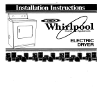
w IMPORTANT Installer: Leave Installation Instructions with the homeowner. Homeowner: Keep Installation Instructions for future reference. Save Installation Instructions for local electrical inspector’s use. Part No. 3389584 Rev. C Large Capacity Thin Twin Washer Dryer 120/240 Volt l -. Before YOU start-e- Check locofion where washer/dryer WIII be Installed Proper Installation 1syour responslbllity Moke sure you hove everyihlng necessary for correct lnstollotlon Important: govermng nrdinancns observe all coaes and Check llmlt or ciornes moblle Contact Grounded eleclrical outlet ISrequired See Electrlcol requIremen& code requirements. Some codes do no1 permit the lnsfallaflon of aryers In garages. closets. homes and sleeplna auarlers. your local bullbln~ltispector provide water pressure Of 5-100 PSI Untape and open washer lid. Remove pockages and hoses from washer. Slondpipe drain system needs a tie-inch diameter stondpipe with mInImum carry-bwoy capoclty of I? gallons per minute. Top of s.ondpipe must be at least 34 Inches high ona than _ ^ no higher , 12 lncnes rrom rIoor Floor drain system requires o siphon break. Port No 285320. ovollable from Whirlpool outhorized ports dGr!butors Waler heater: set to deliver 140°F water to the washer Laundry tub drain system: needs at least o 20.gallon laundry tub Top of tub must be at least 34 Inches high and no higher than 72 inches from floor I Dryer may be exhoustedfrom the rear or left or right side. Exhoustlng through the side requires Port NO. 3391335 See Exhaust requirements. Panel 8. SEE RECESSED AREA INSTRUCTIONS ON BACK COVER. If o longer drain hose is needed, droin hose Part No 388423. and hose extension kit Part No. 285442. are available from Whirlpool outhorzed parts distributors vel floor: maximum slope under washer/dryer. I inch ’ Supporl: floor must be sturdy enough to suppori washer/dryer weight. with water and clothes. of 500 pounds Fire Hazard Do Not use or slore gosoline, polni. Ihinners and other flammable materials near washer/dryer. Fumes lrom such materials could result in fire or explosion. . Never install washer/dryer against draperies or curtains or on carpet. To do so may result in a fire. l Keep any and all ilems from falling or collecting behind the washer/dryer. Failure to do so may result in a fire. . Replace all access panels before operating washer/ dryer. Failure to do so may result in 0 fire or electrical shock. l L Tools and materials needed for installatfon EIectrhI requirements Electrlcal Shock Hazard . Electrical ground is required on this product. . Improper connection oi the equipment-grounding conductor can result in electrical shock. . Check with a qualified electrician if you are in doubt OS to whether the appliance is properly grounded. s Do Not modifv the Dower SUDDIV cord plug. If ii will riot fit the ’ ’ outlet, have a proper outlet rnstalled by a qualified electrician. Modifying the power supply cord plug could result in electrical shock. - Use a new JO-ampere power supply cord kit. Do Not reuse an old power supply cord. Possible electrical shock or fire hazard could occur if old power supply cord is used. v Do Nol use an extensron cord with thus appliance. Such use may result in a fire, electrical shock or other personal injury. B Do Not have a luse in Ihe neutral or grounding circuit. This could result in electrical shock. 1. A three-wire, single phase, 120/240 volt. 60 Hz. AC only electrical supply (or three-wire, 120/208 volt r specified on nameplate) is required on a separate 30ampere circuit. fused on both sides of the line (timedelay fuse or circuit breaker Is recommended). Panel A Polentlal product Damage Do Not store or operate washerldryec below 32°F tsome water may remain in washer). Propef operation reauires temaeratures abbe 45OF. ‘See Use d Care Guide for ‘Winteridng” information. Failure lo lollow above may resull in freeze damage. Localion: should be large enough to open dryer door at least 90”. See back cover for Recessed and closet instollotion instructions and Product dimensions. 2. This washer/ dryer Is equipped with a three-wire, Damp rated flexible-type power supply cord (pIgtoil) with neutrol wire connected to the cabinet. 3 Where local 1~ePtOCle codes permit. It Figure I must be plugged in to a mating Damp receptacle (NEMA type 103oR). See Figure 1. 3. IF THE POWER SUPPLY CORD IS REMOVED. THE WASHER/DRYER MUST BE CONNECTED WITH l&GAUGE MINIMUM COPPER WIRE ONLY. See Ponel F and G. Atternate electrlcal connectlon. for detailed instructions. 4. The power supply cord (pIgtail) can be removed and the appliance con be connected directly to an individuol. X-ampere fuse circuit breaker box through flexible ormored or non-m&allic sheathed, l@oauoe minimum coDDer cable. It isihe~ersonal respar%bil#y and obligation of the customer to contact a quollfled electricion to assure that the electrical lnstollatlon is adequate and is in conformance with National Electrtcal Code ANSI/ NFPA 7Blatest editlon and local codes and ordinances. Allow slack in the line between the wall ond the appliance so that 5 can be moved if servicing Is ever necessary. A U.L.listed stroln relief must be provided at each end of the power supply cable (at the oppllonce and at the iunction box). Four-inch Rrgid Metal Pipe 15preferred Plan instollal!on to use ihe lewest number of elbows and IurnS 5. For four -wire insiollation the threewire power supply cord must be removed and the oppl~ance wiring must be revised. The appltance cabinet must not be grounded to the neutral terminot. but must be connected to the Qroundrng wire (green) of power s6pply cord See Panel G. Alternate electrical connection - Mobile home installation, for detailed instructions. ’ Figure 2 When 0 four-wire receptacle of NEMA Type 14-3X is used (see Figure 2). a matching 120/240 volt minimum. S&ere. U.L.-listed dryer power supply cordkii(pigtail) must be used. This cord contains four No.-10 copper conductors with ring terminals or spade terminals wtth upturned ends on dryer end terminating in CI NEMA Type 14-3DP plug on supply end The fourth (grounding) conductor must be identified by a green or green/yellow cover and the neutral conductor by o white cover. Cord should be Type SRD or SRDT. with U.L.-lied strain relief and be at least four feet long. The power supply cord and strain relief ore not prov-kded with the washer/dryer. Exhaust requfrements ’ i 1 j,’ / Melal flexible duct must be fully extended and supported when the drver ,~ b in its final oosttion. DO NOT KINK OR CRUSH THE DUCT. The metal flexible duct must be completely open to allow adequate exhaust air to flow. Allow OSmuch room OS possible when using elbows or making turns Bend duct gradually to avoid kinkIng. Remove excess flexible duct to &oid sagging and kinking that may resutl in reduced I An Exhaust hood should cap the exhaust duct to prevent exhausted iii.!k air from returning into dryer. The outlet of the hood must be at least 12’ from the ground or any object that mov be in the path of the exhaust The exhaust duct can be routed up. down. left, right or straight out the back of the washer/dryer. Space requirements ore provided on the back cover of Installation Instructions and on the tear panel 01 the washer/dryer. Exhausting the dryer through the side of the washer/dryer requires the use of Side Exhaust. Part No. 3391335. Follow kit installation instructions for proper exhaust installation. E a”” Moximum tength of the exhaust system depends upon the type of duct used; number of elbows and the tvoe of exhaust hood. The maximum length for both rigid and flexible duct is shown in chart 4-inch outtet hood is preferred. However, ct 2-l/2 inch outlet exhaust hood may be used. A 2-l/2 inch outlet creates greater back pressure than other hood types. Fire Hazard Exhausting your dryer indoors is not recommended. The moisture ond linl indoors moy ccruse: . FIRE HAZARD lrom lint collected in dryer; . Moisture domoge to woodwork, furniture. point. woltpaper. carpet. etc.; * Housecleaning problems. possibte health problems. Failure to follow Me above precaution could result in fire domage or personal injury. Fire Hazard Do Not use non-metal, flexible duct. l Do Not use metal duel smaller ihan four inches in diomeler. l Do Not use exhaust hoods wilh magnetic latches. Improper air supply for exhousling may resull in a fire. l Check that exhaust system is not longer than specified. Exhaust syslems longer than specilied wrll: Accumulate lint. Shorten the life of the producl. Reduce performance ond result in longer drying limes and increased energy usage. Failure to follow spectficotions may result in 0 fire. If the washer/dryer is inslolled in o confined area such as o bedroom. bathroom, or closet. it must be exhausted to the outside and provision musl be made for enough air for combustion and ventilation. Check governing codes and ordinances. Also refer to the Recessed and closet installation instructions on the bock cover. l . Do Not exhaust dryer into o chimney. furnace cold ok duct, otttc or CrowI space, or any other duct used for venting l Clean the exhaust syslem every other yeor. l Do Not install llexible duct under wall. ceiling or lloor moleriols. Accumulated lint could resull rn o lire or cause moisture damage. Use duct lope to seal all joints Panel B Mobile For Exhausl systems not covered by the exhaust length chart, see Whirlpool Service Manual. Exhoustina Whirlpool DrverL Pari No 603197 wallable from vow Service check: The back pressure in any exhaust system used must not exceed 0.6 inches of water column measured with on incline manometer at the point that the exhaust duct connects to the dryer. Exhausting the dryer outside is recommended. A closet installation must be exhausted outsde Recessed instollatlon that is’not exhausted outside must use Exhaust Deflector Part NO. 694609 available from your Whirlpool dealer. See Recessed and closet installation instructions on the back cover for odequote unobstructed oir opening reauirements. home installation This appliance is suitable for mobile home installations The installation of the washer/dryer must conform to the Monufoctured Home Construction and Safety Standard. Trtle 24 CFR. Port 3280 (formerly the Federal Standard for Mobile Homes I/ Construction and Safety. Title 24. HUD Port 280. I 1975) or the latest edition Mobile home exhaust requirements: The washer/dryer must have an outside exhaust. If the dryer is exhausted ihrough the floor and the Oreo under the mobile home is enclosed, the exhaust system must terminate outside the enclosed orea. Extension beyond the enclosure WIII prevent lint and moisture buildup under the mobile home. 6. Now Start.. . with washer/dryer area. in laundry Personal Injury Hazard More than one person is required to WI, tilt or move the washer/dryer because of its weight and size. Failure IO lollow these instructions may result in personal injury. I Truck only from the rear to prevent product damage. I Pull the yellow St&ping strap completely oui of the washer/dryec. 3 Remove label that covers the , yellow shipping strop. Pull to Completely remove the Shipping strap from the inside of the washer/dryer. Slide nozzle end of drain hose through the small ‘laop” in the wire form Wrap the hook end of the wire form around the drain hose to form a “hookshape. Do Not force excess length 01 drain hose down the standpipe. This could cause stphantng. Use new hoses and washers that came with your washer/dryer. coupling washer 4. Insert a flai washer into each end of the inlet hoses. Check that washers are firmly seated in couplings. l l l 1 wire form 4 flat. water hose washers 1 grounding wire assembly Remove pork from pOCkOQe. Check that 011parts were ’ included. 2 valve openino tfirst. Then. second hose to top inlet valve. Tighten couplings bv hand: then use Dliers to make an abditionol two-thirds turn. 7 Put ‘hook’ end of drain . hose into laundry tub or stondpipe. Estimate length of drain hose needed when washer/dryer is in finol Dosition. If drain hose is too long - remove clamp ond coupling Cut flexible end of hose. (Do not cut hook-shaped end of drain hose.) Push and twist coupling securely onto drain hose. (You should feel top of drain hose through coupling.) Slide clamp over coupling and hose. II 9. 17. Pull the yellow shipping shop with 3 cotterpins completely out of washer/dryer Install wire form on drain hose. 6. 16. 10. Numbers correspond to steps. Panel C Insert comer posts or other type of suoaorl6 inches tram lett lea. Do Ndt’insed comer posts or otlier support In the center of the washer/dryer. Place hose clamp over washer drain connector. Push coupling end of drain hose onto washer connector. Use pliers to open clamp and slide clamp over drain hose. Check for QOOd fii. 14 If it is not level, carefully n tilt washerldrver backward until front of washer/ dryer Is 3-4 inches off of floor. Insert 4 comer posts under washer/dryer about 6 Inches from the left leg. Loosen nuts on each front leg. Adjust the front legs up or down. Titt washerldwer bockword and remove comer posts. Gently lower the washer/dryer to the floor. Repeat Step 13. If it is still not level, repeat Step 14 and then Step 13 until washer/dryer is level. Potential Floor Damage Slide washer/dryer onto cardboard or hardboard before moving across floor. Failure to do so may cause damage lo floor covering. 9 It you have room to work from either side ot the washer/dryer, move washer/dryer close to final position so you can easily complete the following steps Go to Step 10. n If you are worklng In a closet or recessed area, move the washer/ dryer into its final position and remove cardboard or hardboard from under washer/dryer, Remove crccess panel bv removina three Phillips-head screws and one bumper. located at the top of the access panel. Set panel. screws and bumper aside. (See Step 17. Panel D.) Complete the following steps through the access area. 17 If you did not remove the access panel in Step 9. do so by removing three Phillipshead screws and one bumper. located at the top of the access panel. Set panel. screws and bumper aside. n 18 Determine the length of n exhaust duct that is needed to connect the drver to the exhaust hood (see Exhbust requirements. Panel 6). Connect exhaust duct to the washer/dryer and then to the exhaust hood. nuts on front legs UP tightly against washer/dryer base. If nuts are not tight against washer/dryer base, the washer/dryer may vibrate. . to seal all joints. ” 20 CHECK ELECTRICAL . REQUIREMENTS. BE SURE YOU HAVE CORRECT ELECTRICAL SUPPLY AND RECOMMENDED GROUNDING METHOD. Check the Installation Instructions to see that you have completed each step. Complete any mlssed steps before you continue. 10 Put “hook’ end of droin n hose back in laundry tub or stondpipe. Check for proper length of drain hose. If drain hose is too Iona. disconnect and repeat Steps 7 &id 8. 11 Before attaching water Inlet hoses, run water through both faucets into o bucket. This will get rld of particles in water lines that might clog hoses. 12 Check that all ports ore now Instatlect. (See parts Itst, Panel C.) lf there Is an extra port. go back through steps to see which step was sklpped. n Attach bottom hose (inlet marked “H-) to hot woter faucet. Attach top hose (inlet marked ‘CY to cold water faucet. Tighten the coupling to the faucet bv hand. Use oliers to make final Go-thirds turn Move washer/dryer to its permanent location. Remove cardboard or hardboord from under washer/dryer. 13 n Tllt washer/dryer forward n ralslng back legs 1’ off of floor to adjust rear. setf-leveling legs. Gently lower washer/dryer to floor. Check levelness of the washer/dlyer bv placlnct a carpenter’s level on top of th&washdr,-first side to side, then front to back. If washer/dryer is level. go to Step 15. Panel D CHECKTHAT I KINKED AND I 16 Secure drain hose to tub or standpipe by wrapplng the plastic strap around the hose as shown In Figures A-C. lf draln hose cannot be dropped in place, tt must be cut exactly to length so the ‘hooL’ end is held tighth/ over the edge of the tub or standpipe as shown in Figure D. n 22’ - Check t&t vou removed all the shipping pIekeS IklUdlnQ the yellow shipplng strop with tts 3 cotterpins. Dispose of all shlpping pieces in the proper manner. It you do nol remove the yetlow shipping strap, your washer/dryer may “walk” away Worn Its location. If washer/dryer does operate properly... Check the foIlowIng not to be sure that I Electric supply IS connected 2 House fuse or circuit breaker 1s Intact and light 3 Washer IId or dryer door IS closed 4 Controls are set In a runntng or “ON’ position j Dryer start button has been firmly pushed 6 Make sure yellow shippIng strap has been completely removed 23 24 leak; IS leaking . Check that you of your tools have all Turn on the water . faucets and check for TIghten the couphngs If there 25 Replace the access panel Be sure to tlgh-en the three PhillIps-head sue&s at the top of the access panel. Replace the bumper under the :enter screw. n 26 Read the Use and Core . -to fully understand your new washer/dryer Plug electrical cord Into grounded outle?t Now start the washer and allo~v It to complete the regular cyc e 27 Open the dryer door Check to be sure the ht ‘teen 15 in Its proper position Wipe out the drum I 28 Start the dryer and . allow It to complete cycle to make sure It IS working prop erly 29 with tne Panel E Finally. save all literature and keep washer/dryer n a it During normal business hours the Wh~rloool COOL-LINE” Service WIII answer any questtons about operating or malntainlng you, washer/dryer not covered In you! Ooerailna Instructions The Whirlpool-COOL-LINE* SewIce Dial just number IS (800) 253-1301 as you normally dial long distance the call is free - -. Alternate electrical connection Electrical Shock Hazard . Electrical ground is required on this appliance. . Improper conneclion of the equipment-grounding conductor line con result in electrical shock. . Check with a auakfied eleclrician if ydu are in doubt OS to whether Ihe appliance is properly grounded. - Do NoI modlly the power supply cord plug. If it will not fit the outlet, have a proper outlet installed by a aualilied electrician. . Use Q new 30-ampere power supply cord kit. Do Not reuse on old Dower SUDDIY cord. Possible electrical shdckgr Rre hazard could occur It old power supply cord is used. . Disconnect the power supply cord from Ihe electric supply before making these changes. Failure to do so may result in personal injury. Failure to follows these inslructions could result in electrical shock. This appliance is manufactured the neutral terminal connected the cabinet. with to p Ppe Use grounding wire and clamp assembly (Part No. 685463) or No. IC-gauge minimum copper grounding wire. No. A who Cold waler Figure 8 Connect grounding wire to a grounded cold-water pipe’ with the clamo and then to the external grounding connector on the washer/dryer. (See Figure 3.) Do not ground to a gas supply pipe or holwater pipe. Do not connect the power supply cord to electric power supply until the appliance is permanently grounded. ‘Grounded cold-water pi e mut have metol continuify to &c+rcaf P ground and rubber of not be interrupted by lztlc. 0rnel e~~hicaf 1~10 tPng connecton such OS tlorEs. ntthgs. washer or gaskets (Includl”~ water meter a pump). A,,” ImulaHn comector shtid be eleCtrIca lumped as shown a Ffgwe 7 tim 0 lengm Of NO. 4 tire securely Clamped to bale metal at both ends. F When local codes.. . A. B. Permit use of a flexible type power supply cord (pigtail) that comes equipped with the washer/dryer but Do Not Permit connecting the cabinet-grounding conductor to the neutral wire of the power supply cord: cenlsr sllvercolorad lermlnal tick screw and neuhal we Groundi (green WI “R, Y.IIOW ShlPeer) Do Not Permit the use of the flexible power supply cord equipped with the washer/dryer and Permit solid copper power supply cable and Permit connecting cabinetgrounding conductor to the neutral wire of the power supply cable: Figure 4 Figure 3 1. Disconnect the power supply. 2. Remove terminal block cover. 3. Remove the grounding wire (green with yellow stripes) from the external grounding connector and fasten under center, silver-colored terminal block screw. See Figure 3. 4. Connect a separate copper aroundina wire (NO. IO minimum). . See “To c‘bnnect a separate grounding wire-, Panel F for detailed instructions. 5. Replace the terminal block cover. po;;move To connect a separate grounding wire - Panel When local codes.. . the power supply 1. Disconnect the power supply 2. Remove the terminal block cover from the dryer. 3. Disconnect the power supply cord from the termlnol block. 4. Use a screwdriver to loosen the strain-relief screws. 5. Pull downword on the power supply cord until it is removed from the dryer. See Figure 9. 1. Disconnect the power supply. 2. Remove the power cord equipped with the washer/dryer as instructed. See ‘To remove the power supply cord’. Panel F. 3. Install solid copper, power-supply cable through strain relief. 4. Connect the neutral wire of the flexible armored or non-metallic sheathed, solid copper powerSUDDIV cable to the center. silvercdl&d terminal screw and the terminal block. Connect the other wires to the outer teninals. Tighten screws firmlv See Fiaure 4. For plain-end wires. see:Dlrect wlrlng connection.’ Pcnel F. 5. Replace the terminal block cover, Direct wiring connectton 1, Strip the outer covering back 3 inches from the end exposing the three wires. 2. Strip the lnsulatlon back 1 Inch from the end of each wire. Form the bare wires into a V-shaped hook. See Figure 10. Pblnw7d wlflng Figure IO I: 3. Loosen, do not remove, screws from terminal block. Attach wires according to instructions for type of connection needed, 4. Slide the end of each wire under the screw head with the open side of the screw hook on the right. ._Squeeze the wire rogerner To rorm a loop. 5. Tlghten each screw firmly. 6. Tighten strain relief screws -. When local codes.. . C. Do Not Permit the use of the flexible power SUODIV cord eauiooed with the wash&/dryer and’ Permti copper, power-supply cable and Do Not Pen-nit connecting cabinet-grounding conductor to the neutral wire of the power supply cable: Figure 5 1. Disconnect the power supply. 2. Remove the power supply cord equipped with the washer/dryer as instructed. See “To remove the power supply cord’. Panel F. 3. lnstoll copper, power-supply cable through strain relief. 4. Remove the grounding wire (green with yellow stripes) from the external aroundina connector and fasten under cent&. silver-colored terminal block screw. Panel G Mobile home and four-wire installation 5. Connect the neutral wire of the flexible armored or non-metallic sheathed. copper power-supply cable to the center, sihrer-colored terminal screw of the termlnal block. Connect the other wires to the outer terminals. Tighten screws See Figure 5. For plain-end wires, see ‘Direct wiring connection.’ Panel F. 6. Connect a separate copper grounding wlre (NO. 10 minimum). See ‘To connect a separate grounding wire’, Panel F, for detailed Instructions 7. Replace the terminal block cover. When a four-wire receptacle, NEMA Type 14-3OR is used. a matching 120/240 volt minimum, JOampere. U.L.-llsted dryer power supply cord kit(pigtai0 must be used. This cord contains four, No. 10 copper conductors with ring terminals or spade terrnlnals with upturned ends on dryer end terminating In a NEMA Tvpe 14-30P plug on supply end. Groundlng WI. (green With Figure 6 1. Disconnect the power supply. 2. Remove the power supph/ cord equipped with the washer/dryer as instructed. See Panel F. ‘To remove the power supply cord’. 3. Install copper, 4-wlre power SUDDIV cord or cable throuah strain reiief.‘Trghten strain relief sc;ews. 4. Remove the grounding wire (green with yellow stripes) from the external grounding connector and fasten under center. sitver-colored terminal block screw. 5. Connect the aroundina wire (green with vell6w strip&of the copper. Qwire power supply cord or cable to the external grounding connector. 6. Connect the neutral (white) of the power supply cord or cable to the center. siher-colored terminal screw of the terminal block. Connect the other wires to the O&r termin&. Tighten screws firmly. See Figure 6. For plain-end wires, see ‘Direct wiring connection.’ Panel F. 7. Replace the terminal block cover. -. Recessed and closet installation Product dimensions Recessed, nonexhausted installation must use only the rear exhaust position and Exhaust Deflector Part instructions 3f B NO. 694609. I Fire Hazard l l It is recommended that the dryer be exhausted outside. Failure to do so may result in the risk of tire. If washer/dryer is installed in a closet, the dryer MUST be exhausted outside. Failure to do so may cause a fire. This washer/dryer may be installed in a recessed area ar clasd. The installation spacing l.sIn inches and Is minimum allowable. Additional spacing should be considered for ease of Installation, servicing and compliance with local codes and ordinances. LLi 28 48’ -‘\ i+5 SideWow Rocossed mea mlnlnwm tnrtdatton spoclng. Note: tt recessed Instatlalion Is exhausted t0 the side or rear. 6’ must be availabl? above ~gbyashor/dryer bul all other spactng can +27-3/C If closet door is installed, the minimum unobstructed air openings in top’ond bottom is required, Louvered doors with equivalent air Closet openings are acceptable. installation must be exhausted. Other installations must use the minimum dimensions indicated. To prevent large amounts of lint and moisture from accumulating and to maintain drying efficiency, this appliance should be exhausted outdoors. Front Vtew T&f1 2 Port No 3389584 0 19po WhIrlpool Rev C Corporomn 36. -TM A 24 sq In. f - Prepared by Whirlpool Corporation. 20-l/2 Dmtn 01 COPPauATlON Benton Harbor. Mlchlgon 49022 Punted In U S A