1
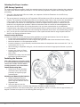
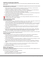
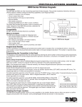
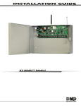
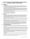
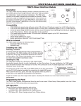
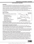
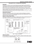
Installation Guide
1184 Wireless Carbon Monoxide Detector
Description
The 1184 is a 3V battery powered wireless carbon
monoxide (CO) detector that provides early warning
when the electrochemical sensing technology measures
carbon monoxide levels in the air.
The detector consists of an electrochemical carbon
monoxide sensor assembly coupled with an 1100 Series
wireless transmitter and an audible sounder. The
transmitter can send alarm, trouble, tamper and low
battery condition messages to the alarm panel.
The 1184 is an ideal carbon monoxide detector for
difficult to wire locations, applications where room
aesthetics are critical or where hazardous materials
exist.
CO ENTRY PORTS
Compatibility
AUDIBLE SOUNDER
Figure 1: Carbon Monoxide Detector
All DMP 1100 Series Wireless Receivers and Panels
What is Included
The 1184 Wireless Carbon Monoxide Detector includes the following items:
• One 1184 Carbon Monoxide Detector with DMP wireless transmitter installed
• One 3V lithium Model CR123-FIRE battery
• Hardware pack
• Zone name and number label
• Serial number labels
Transmitter Serial Number
For your convenience, an additional pre‑printed serial number label is included. Prior to installing the device, record
the serial number or place the pre-printed serial number label on the panel programming sheet. This number is
required during programming. As needed, use the zone name and number label to identify a specific transmitter.
Programming the Transmitter in the Panel
Locate and record the detector serial number. This number is required during programming. Program the device
zone type in Zone Information during panel programming. At the Serial Number: prompt, enter the eight-digit serial
number. Continue to program the zone as directed in the panel programming guide. In addition to the detector’s
audible sounder, if an Emergency zone type (EM) is selected, the bell output can also be programmed for a desired
indication in Bell Options panel programming.
Note: When a receiver is installed, powered up, or the panel is reset, the supervision time for transmitters is reset.
If the receiver has been powered down for more than one hour, wireless transmitters may take up to an additional
hour to send a supervision message unless tripped, tampered, or powered up. This operation extends battery life for
transmitters. A missing message may display on the keypad until the transmitter sends a supervision message.
Detector Annunciation Notifications
The 1184 provides the following transmitter messages, LED display, and audible annunciations:
Message
Alarm
Keypad Display
ALARM
Low battery
LO BAT
Detector head removed
TROUBLE
Tamper
TAMPER (XR100/XR500
XR150/XR350/XR550)
OPEN (XTL/XT30/XT50)
Detector End of Life
TROUBLE
Red LED
Blinks once every
second
Blinks once every 45
seconds
Blinks once every 5
seconds
Off
Green LED
Off
Sounder
Temporal 4
Off
Chirps after 7 days
Off
One chirp every
45 seconds
Off
Blinks once every 10
seconds
Off
On
One chirp every
45 seconds
Selecting the Proper Location
(LED Survey Operation)
For optimum wireless performance, install the transmitter away from large metal objects. Mounting the transmitter
on or near metal surfaces impairs performance. For the LED Survey Operation complete the following steps before
proceeding:
1. Since the 1184 transmitter PCB is not visible, use a separate 1100 Series Transmitter for the LED Survey
Operation such as an 1107.
2. The survey button is located on the 1107 transmitter PCB and the survey LED can be seen near the survey button
location. The transmitter PCB Red Survey LED turns on whenever data is sent to the receiver then immediately
turns off when the receiver acknowledgement is received. Pressing the tamper switch is a convenient way
to send data to the receiver to confirm operation. When the tamper switch is pressed or released, the LED
blinks once to indicate proper operation. When the transmitter does not receive an acknowledgement from
the receiver the LED remains on for about 8 seconds to let you know communication is not established.
Communication is also faulty when the LED blinks multiple times in quick succession. Relocate the transmitter or
receiver until the LED immediately turns off indicating the transmitter and receiver are communicating properly.
3. Also, you can test the communication between the control panel and the detector using the panel walk test
feature. See Testing the Detector Alarm.
General Location Guidelines
In addition to NFPA 720, use the following location guidelines to optimize performance from the CO detector:
• Locate ceiling-mounted detectors at least 12 inches from any wall
• Locate wall-mounted detectors at least as high as the light switch and at least 6 inches from the ceiling.
• Mount the detector on a firm permanent surface
• Locate the detector in environmentally controlled areas where the temperature does not exceed 104° F (40° C)
or drop below 32° F (0° C).
• When mounting to suspended ceiling tile, the tile must be secured with the appropriate fastener to prevent
tile removal
• Locate in the vicinity of flamefueled appliances, but no closer
than 10 feet.
• Keep detectors away from vents and
the reach of children and pets.
Installing the Detector
Note: When setting up a wireless system,
it is recommended to program zones and
connect the wireless receiver before
installing batteries in the transmitters.
Install the Mounting Base
1. Using the two screws provided,
mount the base in the location
previously surveyed for proper
communication.
Attaching and Removing the Detector
1. Using the alignment notch on
the lip of the mounting base as a
guide, align the detector with the
alignment tabs.
Figure 2: Exploded View of CO Detector
2. Insert the detector into the
mounting base and turn clockwise approximately 15 degrees to snap into place.
To remove the detector from the mounting base, grasp the detector and turn it counterclockwise approximately 15
degrees. The detector snaps off of the mounting base. See Figure 2.
Digital Monitoring Products
2
1184 Detector Installation Guide
Installing or Replacing the Batteries
Observe polarity when installing the battery. Use only 3.0V lithium batteries, DMP Model CR123-FIRE or Panasonic
Model CR123A.
Note: When setting up a wireless system, it is recommended to program zones and connect the receiver before
installing batteries in the transmitters.
1. Remove the detector from the mounting base by grasping the detector and turning it counterclockwise
approximately 15 degrees. The detector snaps off of the mounting base.
2. The battery is located on the inside of the detector. The detector is supplied with a pre-installed battery.
During the initial installation simply remove the battery pull tab to begin operation.
3. If replacing the battery, remove the old battery and dispose of properly.
4. Observing correct polarity, insert the new 3V lithium battery into the battery compartment and replace the
cover. Use only new batteries when replacing old ones.
5. Reattach the detector to the mounting base. See Attaching and Removing the Detector.
6. Test the detector. See Testing the Detector.
Caution: Properly dispose of used batteries. Do not recharge, disassemble, heat above 212°F (100°C), or
incinerate. Risk of fire, explosion, and burns.
Testing the Detector Alarm
Wireless Communication
1. To test the detector’s alarm, enable Walk Test operation on the control panel. If the system is monitored, the
system sends a System Test Begin report (System message S66) to the central station.
To conduct the Walk Test, reset the control panel by momentarily placing a jumper on J16. From the keypad,
enter the code 8144. The keypad displays WALK TEST. Refer to the panel programming guide for complete
information on Walk Test operation.
2. Insert a small screwdriver into the Test hole on the front of the detector to activate the test, sound the
detector’s audible and send a message. Verify that the walk test trip counter increments to indicate a
successful test.
3. Select END to stop the Walk Test. When the Walk Test ends or a 20-minute time-out expires, a final Sensor
Reset occurs. The System Test End message (System message S67) is sent to the central station along with
verify and fail messages for each zone under test. Faulted zones then display on the keypad.
Important: The control panel alarm and all auxiliary functions should be verified for a complete test of the system.
See the panel programming guide for additional information.
Detector Sensitivity
1. With a small screwdriver, press and hold the recessed Test switch on the detector for approximately 2
seconds. The detector will temporarily sound an alarm and the red LED will illuminate.
2. Within a few seconds the green LED will start to blink rapidly indicating the detector is in functional test
mode awaiting gas entry.
3. Spray a very small amount of Solo brand C6 canned CO, available at most local security distributors or online,
into one of the 3 small gas entry holes located on the top center of the detector.
4. Upon successful gas entry and if functioning properly, the detector will alarm by sounding in a Temporal 4
pattern with the red LED blinking. An alarm signal will be sent to the panel providing verification of alarm
signal.
5. The alarm condition at the detector will time out in 20 to 60 seconds or when the CO gas has cleared.
6. If gas entry is unsuccessful, the test will time out after 27 seconds.
7. Reset the panel as needed.
Important: Before testing, be sure to notify the central station to avoid false alarms.
Battery Life Expectancy
Typical battery life expectancy for DMP wireless CO detectors is at least 2 years. DMP wireless equipment uses twoway communication to extend battery life.
The following situations can reduce battery life expectancy:
• If a receiver is unplugged or not installed.
• Frequent transmissions, such as how often the detector is tested.
• When installed in extreme hot or cold environments.
1184 Detector Installation Guide
Digital Monitoring Products
3
FCC Information
This device complies with Part 15 of the FCC Rules. Operation is subject to the following two conditions:
(1) This device may not cause harmful interference, and
(2) this device must accept any interference received, including interference that may cause undesired operation.
Changes or modifications made by the user and not expressly approved by the party responsible for compliance could
void the user’s authority to operate the equipment.
NOTE: This equipment has been tested and found to comply with the limits for a Class B digital device, pursuant
to part 15 of the FCC Rules. These limits are designed to provide reasonable protection against harmful
interference in a residential installation. This equipment generates, uses and can radiate radio frequency
energy and, if not installed and used in accordance with the instructions, may cause harmful interference
to radio communications. However, there is no guarantee that interference will not occur in a particular
installation. If this equipment does cause harmful interference to radio or television reception, which can be
determined by turning the equipment off and on, the user is encouraged to try to correct the interference by
one or more of the following measures:
- Reorient or relocate the receiving antenna.
- Increase the separation between the equipment and receiver.
- Connect the equipment into an outlet on a circuit different from that to which the receiver is connected.
- Consult the dealer or an experienced radio/TV technician for help.
NOTE: The 1100 Series wireless system is a two-way supervised wireless design. It is compliant with FCC rules as
they pertain to 900 MHz Spread Spectrum devices. In rare instances it has been observed that certain 900
MHz cordless telephones may occasionally experience a clicking sound on the telephone while in use. If
this occurs, it may be resolved by selecting a different channel on the cordless telephone, or replacing the
cordless phone with a different brand or model of 900 MHz telephone or other cordless telephone.
To comply with RF exposure requirements, a minimum distance of 20cm must be maintained between the
antenna and all persons.
Industry Canada Information
This device complies with Industry Canada Licence-exempt RSS standard(s). Operation is subject to the following
two conditions: (1) this device may not cause interference, and (2) this device must accept any interference,
including interference that may cause undesired operation of the device.
Le présent appareil est conforme aux CNR d’Industrie Canada applicables aux appareils radio exempts de licence.
L’exploitation est autorisée aux deux conditions suivantes : (1) l’appareil ne doit pas produire de brouillage, et (2)
l’utilisateur de l’appareil doit accepter tout brouillage radioélectrique subi, même si le brouillage est susceptible
d’en compromettre le fonctionnement.
Compatibility
Battery
Life Expectancy At least 2 years
(normal operation)
3.0V Lithium
CR123-FIRE
See Battery Life Expectancy for full details.
Low battery 2.7V
Frequency Range
905 - 924 MHz
Dimensions
5.8” x 2.2”
(14.3cm x 6.1cm)
ColorWhite
Patents
U. S. Patent No. 7,239,236
1100D Wireless Receiver
1100DH Wireless High Power Receiver
1100DI Wireless In-line Receiver
1100X Wireless Receiver
1100XH Wireless High Power Receiver
XTL Series Panels with integrated wireless receiver
XTLN / XTLN-WiFi Panel
XT50 Series Panel with integrated wireless receiver
XT30 Series Panel
XR100/XR500 Series Panel
XR150/XR350/XR550 Series Panel
Listings and Approvals
FCC Part 15: CCKPC0104
New York City 1100 Series Wireless (FDNY COA #6167)
Industry Canada: 5251A-PC0104
Underwriters Laboratories (UL) Listed
ANSI/UL 2075 Gas and Vapor Detectors and Sensors
800-641-4282
INTRUSION • FIRE • ACCESS • NETWORKS
www.dmp.com
2500 North Partnership Boulevard
Designed, Engineered
and Assembled in U.S.A.
Springfield, Missouri 65803-8877
LT-1196 1.03 © 2014 Digital Monitoring Products, Inc.
14405
Specifications