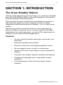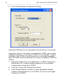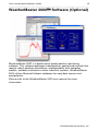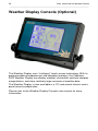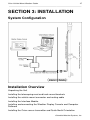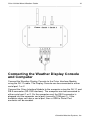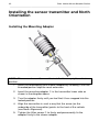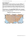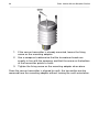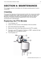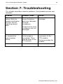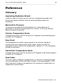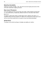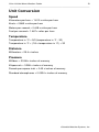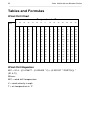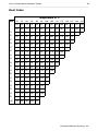
1
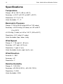
Orion Vehicle Mount Weather Station 1 ________________________________________________________________________ Orion Vehicle Mount Weather Station™ User Manual Version 1.02 All specifications subject to change without notice. Printed in U. S. A. Columbia Weather Systems, Inc. 2 Orion Vehicle Mount Weather Station ________________________________________________________________________ © Copyright 2006 Columbia Weather Systems, Inc. All Rights Reserved. Proprietary Notice: Orion, Orion 510, Orion Vehicle Mount, Capricorn 2000, Capricorn 2000MP and Capricorn 2000EX are trademarks of Columbia Weather Systems, Inc. The information and drawings contained herein are the sole property of Columbia Weather Systems, Inc. Use of this publication is reserved exclusively for customers of Columbia Weather Systems, Inc. and their personnel. Reproduction of this material is forbidden without the express written consent of Columbia Weather Systems, Inc. Parts of the Orion Vehicle Mount Weather Station™ user manual were adapted from the Weather Transmitter WXT510 User’s Guide with permission from Vaisala Oyj. WINDCAP®, RAINCAP®, HUMICAP®, BAROCAP® and THERMOCAP® are registered trademarks of Vaisala. Orion Vehicle Mount Weather Station 3 ________________________________________________________________________ Welcome! Welcome to the Columbia Weather Systems family of users and congratulations on your purchase of the Orion Weather Station. The Orion Vehicle Mount Weather Station is quite easy to install and you may be tempted to skip the installation procedure or other portions of this manual. We recommend that you resist that urge. A thorough knowledge of these installation and calibration procedures will greatly increase the usefulness and the accuracy of your instrument. In particular, a proper installation will help prevent problems with both operation and maintenance. Please read this manual completely prior to installation. Columbia Weather Systems, Inc. 4 Orion Vehicle Mount Weather Station ________________________________________________________________________ Orion Vehicle Mount Weather Station 5 ________________________________________________________________________ Important Notice: Shipping Damage BEFORE YOU READ ANY FURTHER, please inspect all system components for obvious shipping damage. The Orion 510 is a high precision instrument and can be damaged by rough handling. Your unit was packaged to minimize the possibility of damage in transit. Therefore, we recommend that you save the shipping container for any future shipment of your Orion unit. In the event your order arrives in damaged condition, it is important that the following steps be taken immediately. The title transfers automatically to you, the customer, once the material is entrusted to the transport company. NOTE: DO NOT RETURN THE INSTRUMENT TO COLUMBIA WEATHER SYSTEMS until the following steps are completed. Failure to follow this request will jeopardize your claim. 1. Open the container and inspect the contents. Do not throw away the container or any damaged parts. Try to keep items in the same condition as originally received. 2. Notify the transport company immediately in writing, preferably by facsimile, about the shipping damage. 3. Wait for the transport company’s representative to inspect the shipment personally. 4. After inspection, request permission from Columbia Weather Systems for return of the damaged instrument by calling the Service Department, (503) 629-0887. 5. Return approved items to us at the following address: Columbia Weather Systems, Inc. 2240 NE Griffin Oaks Street, Suite 100 Hillsboro, OR 97124 6. After return authorization is issued and we receive the instrument, an estimate of the cost of repair will be sent to you for submittal to the transport company as a claim. Columbia Weather Systems, Inc. 6 Orion Vehicle Mount Weather Station ________________________________________________________________________ ESD Protection Electrostatic Discharge (ESD) can cause immediate or latent damage to electronic circuits. Vaisala products are adequately protected against ESD for their intended use. However, it is possible to damage the product by delivering electrostatic discharges when touching, removing, or inserting any objects inside the equipment housing. To make sure you are not delivering high static voltages yourself: 1. Handle ESD sensitive components on a properly grounded and protected ESD workbench. When this is not possible, ground yourself with a wrist strap and a resistive connection cord to the equipment chassis before touching the boards. When neither of the above is possible, at least touch a conductive part of the equipment chassis with your other hand before touching the boards. 2. Always hold the boards by the edges and avoid touching the component contacts. Orion Vehicle Mount Weather Station 7 ________________________________________________________________________ Table of Contents WELCOME! ..................................................................................3 IMPORTANT NOTICE: SHIPPING DAMAGE .......................5 ESD PROTECTION ............................................................................................. 6 SECTION 1: INTRODUCTION ................................................11 THE ORION WEATHER STATION ..................................................................... 11 Features:.................................................................................................... 11 SPECIFICATIONS .............................................................................................. 12 Temperature............................................................................................... 12 Barometric Pressure .................................................................................. 12 Wind Speed ................................................................................................ 12 Wind Direction........................................................................................... 12 Relative Humidity....................................................................................... 12 Rainfall ...................................................................................................... 13 Input Voltage.............................................................................................. 13 Heating Power Source ............................................................................... 13 PRINCIPLES OF MEASUREMENTS ..................................................................... 14 Wind Measurement .................................................................................... 14 Barometric Pressure, Temperature, and Relative Humidity (PTU) Module ................................................................................................................... 15 Rainfall Measurement................................................................................ 16 SECTION 2: PHYSICAL DESCRIPTION...............................17 ORION 510 SENSOR TRANSMITTER ................................................................. 17 Sensor Transmitter Components ................................................................ 17 Mounting Adapter ...................................................................................... 19 Internal Terminal Block............................................................................. 19 Heating (Optional)..................................................................................... 21 Orion Interface Module ............................................................................. 22 ORION DATA MANAGER SOFTWARE............................................................... 23 Orion Data Manager Installation and Configuration................................ 23 WEATHERMASTER 2000 SOFTWARE (OPTIONAL) ....................................... 25 WEATHER DISPLAY CONSOLE (OPTIONAL) .................................................... 26 SECTION 3: INSTALLATION .................................................27 SYSTEM CONFIGURATION ............................................................................... 27 INSTALLATION OVERVIEW.............................................................................. 27 UNPACKING THE UNIT .................................................................................... 28 INSTALLING THE TELESCOPING MAST AND VEHICLE-MOUNT BRACKETS ......... 29 INSTALLING THE VEHICLE MOUNT SENSOR CONNECTOR AND ROUTING CABLE 30 INSTALLING THE INTERFACE MODULE............................................................ 30 Columbia Weather Systems, Inc. 8 Orion Vehicle Mount Weather Station ________________________________________________________________________ CONNECTING THE WEATHER DISPLAY CONSOLE AND COMPUTER ................. 31 INSTALLING THE SENSOR TRANSMITTER AND NORTH ORIENTATION .............. 32 Installing the Mounting Adapter ................................................................ 32 North Alignment......................................................................................... 33 SECTION 4: OPERATION ........................................................35 COMMUNICATION SETTINGS ........................................................................... 35 WEATHER SOFTWARE ..................................................................................... 35 TERMINAL COMMANDS .................................................................................. 35 Displaying current sensor readings ........................................................... 35 CONTINUOUS DISPLAY OF WEATHER INFORMATION ........................................ 36 SECTION 5: CALIBRATION....................................................39 CALIBRATING THE BAROMETRIC PRESSURE SENSOR ...................................... 39 Altitude Setting........................................................................................... 39 Optional Calibration Procedure ................................................................ 39 CALIBRATING THE TEMPERATURE SENSORS ................................................... 40 SECTION 6: MAINTENANCE .................................................41 CLEANING....................................................................................................... 41 REPLACING THE PTU MODULE....................................................................... 41 FACTORY CALIBRATION AND REPAIR SERVICE .............................................. 42 SECTION 7: TROUBLESHOOTING.......................................43 SECTION 8: USER SUPPORT INFORMATION ...................45 LIMITED WARRANTY ...................................................................................... 45 EXCLUSIONS ............................................................................................ 45 RETURN FOR REPAIR PROCEDURE .................................................................. 46 REFERENCE...............................................................................49 GLOSSARY ...................................................................................................... 49 Aspirating Radiation Shield ....................................................................... 49 Barometric Pressure .................................................................................. 49 Celsius Temperature Scale......................................................................... 49 Dew Point .................................................................................................. 49 Fahrenheit Temperature Scale................................................................... 49 Heat Index.................................................................................................. 49 Relative Humidity....................................................................................... 50 Sea Level Pressure..................................................................................... 50 Wind Chill .................................................................................................. 50 UNIT CONVERSION ......................................................................................... 51 Speed.......................................................................................................... 51 Temperature............................................................................................... 51 Distance ..................................................................................................... 51 Orion Vehicle Mount Weather Station 9 ________________________________________________________________________ Pressure ..................................................................................................... 51 TABLES AND FORMULAS ................................................................................. 52 Wind Chill Chart........................................................................................ 52 Wind Chill Equation .................................................................................. 52 Heat Index.................................................................................................. 53 Dew Point .................................................................................................. 54 Columbia Weather Systems, Inc. 10 Orion Vehicle Mount Weather Station ________________________________________________________________________ Orion Vehicle Mount Weather Station 11 ________________________________________________________________________ SECTION 1: INTRODUCTION The Orion Weather Station Utilizing cutting-edged ultrasonic technology at an amazingly affordable price, the Orion Weather Station is the newest product in our family of innovative weather monitoring systems. Orion provides ultrasonic wind direction and speed measurements, a highly-accurate impact rain sensor, capacitive relative humidity, temperature and barometric pressure readings – all in a single sensor module. High accuracy and fine resolution make this new system ideal for precision weather monitoring. Orion’s sensors meet FAA and WMO specifications for aviation operations, as well as EPA requirements for scientific environmental monitoring applications. Features: • Six most essential weather parameters measured in one instrument • Accurate and stable measurement • Ultrasonic wind sensor and impact precipitation sensor • No moving parts means virtually no maintenance • Optional LCD touch-screen display console and powerful software • Low power consumption improves reliability and longevity • Compact and lightweight with a single cable for quick installation • 9-ft telescoping mast with truck mount quick release hardware Columbia Weather Systems, Inc. 12 Orion Vehicle Mount Weather Station ________________________________________________________________________ Specifications Temperature Range: -60 to 140°F (-52 to +60°C) Accuracy: ±-0.5°F (±0.3°C) at 68°F (+20°C) Resolution: 0.1°F (0.1°C) Units Available: °F, °C Barometric Pressure Range: 17.50 to 32.50 InHg (600 to 1100 mbar) Accuracy: ±0.015 InHg (0.5 mbar) at +32 to 86°F (0 to 30°C) ±0.03 InHg (1 mbar) at -60 to 140°F (-52 to 60°C) Resolution: 0.01 InHg (0.1 mbar) Units Available: Kpa, mbar, InHg Wind Speed Range: 0 - 115 mph (0 - 60 m/s) Accuracy: ±0.7 mph (±0.3 m/s) Resolution: 1 mph (1 m/s) Units Available: knots, mph, km/hr, m/s Wind Direction Azimuth: 0 - 360° Accuracy: ±2° Resolution: 1° Relative Humidity Range: 0 - 100%RH Accuracy: ±3%RH (0-90%), ±5% (90-100%) Resolution: 1%RH Units Available: %RH Orion Vehicle Mount Weather Station 13 ________________________________________________________________________ Rainfall Range: cumulative Collection Area: 60 cm2 Accuracy: ±5% (spatial variations may exist) Resolution 0.01 in. (0.254mm ) Units Available: mm, inches Input Voltage The Orion is supplied with a wall mount transformer Input: 120 VAC, 60 HZ, 16 W Output: 12 VDC, 800 mA The Orion can also be powered directly using a DC voltage source Input: 5 to 30 VDC (60 mA at 12 VDC) Heating Power Source Input: 5 to 30 VDC (1.1 A at 12 VDC) Columbia Weather Systems, Inc. 14 Orion Vehicle Mount Weather Station ________________________________________________________________________ Principles of Measurements Wind Measurement Both wind speed and direction are measured using advanced ultrasonic technology. The sensor utilizes ultrasound to determine horizontal wind readings. The array of three equally-spaced ultrasonic transducers on a horizontal plane is an ideal design that ensures accurate wind measurement from all directions, without blind angles or corrupted readings. The wind sensor has no moving parts, which makes it virtually maintenance free. The wind sensor has an array of three equally spaced ultrasonic transducers on a horizontal plane. Wind speed and wind directions are determined by measuring the time it takes the ultrasound to travel from each transducer to the other two. The wind sensor measures the transit time (in both directions) along the three paths established by the array of transducers. This transit time depends on the wind speed along the ultrasonic path. For zero wind speed, both the forward and reverse transit times are the same. With wind along the sound path, the up-wind direction transit time increases and the down-wind transit time decreases. The wind speed is calculated from the measured transit times using the following formula: Vw = 0.5 x L x (1/ tf – 1/tr where: Vw = Wind speed L = Distance between the two transducers tf = Transit time in forward direction tr = Transit time in reverse direction Measuring the six transit times allows Vw to be computed for each of the three ultrasonic paths. The computed wind speeds are independent of altitude, temperature and humidity, which are cancelled out when the transit times are measured in both directions, although the individual transit times depend on these parameters. Using Vw values of two array paths is enough to compute wind speed and wind direction. A signal processing technique is used so that wind speed and wind direction are calculated from the two array paths of best quality. Orion Vehicle Mount Weather Station 15 ________________________________________________________________________ The wind speed is represented as a scalar speed in selected units (m/s, kt, mph, km/h). The wind direction is expressed in degrees (°). The wind direction reported indicates the direction that the wind comes from. North is represented as 0°, east as 90°, south as 180°, and west as 270°. The wind direction is not calculated when the wind speed drops below 0.05 m/s. In this case, the last calculated direction output remains until the wind speed increases again to the level of 0.05 m/s. The average values of wind speed and direction are calculated as a scalar average of all samples over the selected averaging time (1 ... 900 s). The sample count is based on a 4 Hz sampling rate. The minimum and maximum values of wind speed and direction represent the corresponding extremes during the averaging time. Barometric Pressure, Temperature, and Relative Humidity (PTU) Module Barometric pressure, temperature, and humidity measurements are combined in an advanced sensor module (PTU) utilizing a capacitive measurement method for each parameter. The PTU module contains separate sensors for pressure, temperature, and humidity measurement. The measurement principle of the pressure, temperature, and humidity sensors is based on an advanced RC oscillator and two reference capacitors against which the capacitance of the sensors is continuously measured. The microprocessor of the transmitter performs compensation for the temperature dependency of the pressure and humidity sensors. Barometric pressure is measured using a capacitive silicon BAROCAP® sensor. The sensor has minimal hysteresis and excellent repeatability, as well as outstanding temperature and long-term stability. Temperature is measured with a capacitive ceramic THERMOCAP® sensor. Relative humidity measurement is based on a capacitive thin film polymer HUMICAP®180 sensor. The sensor is highly accurate with negligible hysteresis and excellent long-term stability in a wide range of environments. Radiation Shield: This module is mounted in a specially-designed radiation shield which protects the sensors from both scattered and direct sunlight and precipitation. The composite material in the plates offers excellent thermal characteristics and UV stabilized construction. The white outer surface reflects radiation, while the black inside absorbs accumulated heat. Columbia Weather Systems, Inc. 16 Orion Vehicle Mount Weather Station ________________________________________________________________________ The internal sensor module is easily replaceable and readily available as a spare component. To order a replacement module, please use catalog no. 9581. Rainfall Measurement Rainfall is measured with an impact sensor, which detects the size and impact of individual rain drops. The signals resulting from the impacts are proportional to the volume of the drops. Hence, the signal from each drop can be converted directly to the accumulated rainfall. This measurement method eliminates flooding and clogging, as well as wetting and evaporation losses. The sensor transmitter uses RAINCAP® sensor 2 technology in precipitation measurement. The precipitation sensor comprises of a steel cover and a piezoelectrical sensor mounted on the bottom surface of the cover. The precipitation sensor detects the impact of individual raindrops. The signals from the impact are proportional to the volume of the drops. Hence, the signal of each drop can be converted directly to accumulated rainfall. Advanced noise filtering technique is used to filter out signals originating from other sources than raindrops. The measured parameter is accumulated rainfall. Detection of each individual drop enables computing of rain amount with high resolution. Orion Vehicle Mount Weather Station 17 ________________________________________________________________________ SECTION 2: PHYSICAL DESCRIPTION Orion 510 Sensor Transmitter The Orion 510 Sensor Transmitter is an all-in-one sensor unit containing ultrasonic wind speed and direction sensor, temperature sensor, relative humidity sensor, barometric pressure sensor and an impact rain sensor. The temperature, relative humidity and barometric pressure sensors are combined in a single module housed in a self-aspirating radiation shield. Sensor Transmitter Components 1: Top of the transmitter 2: Radiation Shield 3: Bottom of the transmitter 4: Screw conver Columbia Weather Systems, Inc. 18 Orion Vehicle Mount Weather Station ________________________________________________________________________ Cut Away View 1: Wind Transducers (3 pcs) 2: Precipitation Sensor 3: Pressure sensor inside the Sensor Module 4: Humidity and temperature sensor inside the Sensor Module Bottom of the Transmitter 1: Alignment direction sign 2: Service port 3: Water tight cable gland 4: Unused cable gland, covered 5: Connector (not available with Orion) Orion Vehicle Mount Weather Station 19 ________________________________________________________________________ Mounting Adapter To facilitate easy installation and north alignment, the Orion 510 Sensor Transmitter comes standard with a mounting adapter. The mounting adapter is easily connected on the end of the mast and the sensor transmitter simply snaps into it. The north alignment needs to be performed only once. Internal Terminal Block The sensor transmitter is shipped with a one (1) foot cable terminated by an 8-pin connector half. This cable is connected to the sensor transmitter via a terminal block. The Orion sensor transmitter has a standard RS-232 wiring as shown bellow: Columbia Weather Systems, Inc. 20 Orion Vehicle Mount Weather Station ________________________________________________________________________ Terminal Number 3 5 6 19 20 Signal TXRXD SGND VINVIN+ Color Orange Black Green White Red For heated sensor transmitters, terminal 17 (HTG-) is connected to the Blue wire and terminal 18 (HTG+) is connected to the Brown wire. Orion Vehicle Mount Weather Station 21 ________________________________________________________________________ Heating (Optional) Heating elements located below the precipitation sensor and inside the wind transducers keeps the precipitation and wind sensors free from snow and ice. A heating temperature sensor (Th) underneath the precipitation sensor controls the heating. Three fixed temperature limits, namely +3 °C, -2 °C, and -4 °C (+37 °F, +38 °F, +25 °F) control the heating power as follows: Th > +3 °C heating is off -2 °C < Th < +3 °C 50% heating power -4 °C < Th < -2 °C 100% heating power Th < -4 °C 50% heating power Columbia Weather Systems, Inc. 22 Orion Vehicle Mount Weather Station ________________________________________________________________________ Orion Interface Module The Orion Interface Module is used to supply power to the sensor transmitter and to provide two RS-232 communication ports. The RS-232 ports can be connected to computers, display consoles, transceivers, and other such devices. Orion Vehicle Mount Weather Station 23 ________________________________________________________________________ Orion Data Manager Software The Orion Data Manager Software is a virtual Control Module that communicates with the Sensor Transmitter, collects and processes the sensor data and makes it available to over a virtual serial port for other weather software packages such as WeatherMaster 2000 or any terminal programs such as Hyper Terminal. The Orion Data Manager is only needed if a software viewing option is required. The Data Manager is not needed with the Weather Display Console. Orion Data Manager Installation and Configuration 1. Insert the software CD into drive. 2. Wait for the Autorun to start the installation or run setup.exe. 3. Follow the instructions on the screen to finish the installation. 4. When the installation is finished, the Orion Data Manager will automatically start. Click OK 5. In the System Tray, you will see the Orion Data Manager icon. Right click on the icon to display the menu items. Start Orion Data Manager Stop Orion Data Manager Configure… Exit Select Configure… Columbia Weather Systems, Inc. 24 Orion Vehicle Mount Weather Station ________________________________________________________________________ 6. Orion Data Manager Configuration Dialog: Select the COM port for the input data from the Sensor Transmitter. Usually the Sensor Transmitter is connected to COM1, but in newer notebook computers, a serial port (COM1) is not available. To get a serial port, use a USB to serial converter or a serial port computer card. The USB to serial converters are usually installed on COM 4 or COM 5. 7. Select the Output Port. The default port is COM 8. Change the default port if it is used by another program or if the weather software does not go up to COM 8. 8. Click OK to close the Configuration dialog. 9. Install WeatherMaster software or other compatible weather software and configure it to use COM 8. Or you can use Hyper Terminal on COM 8. Orion Vehicle Mount Weather Station 25 ________________________________________________________________________ WeatherMaster 2000 Software (Optional) WeatherMaster 2000 is a professional grade weather monitoring software. This software package is designed for specialized markets that require robust weather calculations, interoperability with computer models, and data interfaces to other industrial systems. WeatherMaster 2000 utilizes Microsoft Access database for easy data access and manipulation. Please refer to the WeatherMaster 2000 user manual for more information. Columbia Weather Systems, Inc. 26 Orion Vehicle Mount Weather Station ________________________________________________________________________ Weather Display Console (Optional) The Weather Display uses “intelligent” touch-screen technology. With its programmable microprocessor and abundant memory, the Capricorn 2000 Weather Display can display weather information, perform complex computations, and store relatively large amounts of weather data. The Weather Display is also available in a 19” rack-mount chassis and a panel-mount configuration. Please refer to the Weather Display Console user manual for more information. Orion Vehicle Mount Weather Station 27 ________________________________________________________________________ SECTION 3: INSTALLATION System Configuration Installation Overview Unpacking the Unit Installing the telescoping mast and truck-mount brackets Installing the vehicle mount connector and routing cable Installing the Interface Module Installing and connecting the Weather Display Console and Computer Software Installing the Orion sensor transmitter and Quick-North Orientation Columbia Weather Systems, Inc. 28 Orion Vehicle Mount Weather Station ________________________________________________________________________ Unpacking the Unit The sensor transmitter comes in a custom shipping container. Be careful when removing the device. CAUTION: Beware of damaging any of the wind transducers located at the top of the three prongs. Dropping the device can break or damage the transducers. If any the prongs bends, twists, or becomes misaligned, re-aligning the sensor can be difficult or impossible. Unpack the Orion weather station and verify that all parts are included. 1. Standard system includes: Orion WXT510 Sensor Transmitter 15 ft external sensor cable and male sensor connector (plus additional cable lengths, if ordered) 50 ft internal cable with vehicle mount female sensor connector (plus additional cable lengths, if ordered) and allweather connector cap Orion Interface Module (2) 3-positon terminal block connectors Interface module power supply Orion Data Manager Software User Manual 6-foot RS-232 cable (plus additional cable lengths, if ordered) 9 ft telescoping mast with vehicle-mount brackets Mast extension sleeve adapter 2. Weather Display Console (Optional) Display Console Power supply 6-foot RS-232 cable (plus additional cable lengths, if ordered) User Manual 3. WeatherMaster Software, with User Manual (Optional) Inspect all system components for obvious shipping damage (Refer to “Important Notice: Shipping Damage” in case of damage). Orion Vehicle Mount Weather Station 29 ________________________________________________________________________ Save the shipping carton and packing material in case the unit needs to be returned to the factory. If the system does not operate or calibrate properly, see Section 6: Maintenance and Section 7: Troubleshooting, for further instructions. Installing the telescoping mast and vehicle-mount brackets 1. Select a location on the vehicle where the Orion sensor mast will be installed. 2. There are three mounting brackets that come with the mast. Two of the brackets will be permanently mounted to the vehicle for quick and easy set up. These mounting brackets consist of one mounting base plate and one spring-loaded securing mounting bracket. The third bracket is attached to the mast and mates with the slot on the spring-loaded mounting bracket. This bracket may be loosened and re-positioned on the mast to fit the installation scheme and mounting bracket positioning. 3. Ensure the vehicle-mount sensor connector is in close proximity to the mast’s mounting bracket location (refer to the vehicle-mount sensor connector section below). Mark and drill the appropriate mounting bracket holes. Be sure to allow for sufficient structural backing, to adequately support the mast and sensor. 4. External sensor cabling is intended to freely hang along the side of the mast. This assures the mast’s easy extension and retraction without pinching, crimping, or cutting the sensor cable. Users may tie-wrap the cable to the lower portion of the mast to keep it from flagging in the wind. The external sensor cable has a male connector that couples to the vehicle-mount female connector on the side of the vehicle. 5. Extending the mast. At the top of the nested mast there is a large textured locking ring which loosens and tightens the mast extension. A counter-clockwise rotation loosens the ring and allows the mast to be fully extended. Clockwise ring rotation tightens the extension in place. Columbia Weather Systems, Inc. 30 Orion Vehicle Mount Weather Station ________________________________________________________________________ Installing the vehicle mount sensor connector and routing cable 1. To install the female vehicle-mount sensor connector, drill a ¾” hole in close proximity to the sensor mast mounting bracket installation. A recommended location is near the mast’s lower base bracket. 2. Drill four small pilot holes for the mounting screws. 3. Run 25-ft cable through the hole and route to the Orion Interface Module location. 4. Connect the cable to the 3-position connectors, as listed in the chart below. 5. Affix the connector with mounting screws on the external side of the vehicle and ensure the associated all-weather connector cap is securely attached. Installing the Interface Module Using a #1 Straight Slot screwdriver, attach the wires from the end of the sensor cable to the terminal block screws on the Interface Module as follows: Terminal Number 1 2 3 4 5 6 Signal +12 V Ground No Connection Signal Ground RX TX Color RED White and Bare Green Black Orange Orion Vehicle Mount Weather Station 31 ________________________________________________________________________ Connecting the Weather Display Console and Computer Connect the Weather Display Console to the Orion Interface Module using the RJ-11 cable. The Display Console can be connected to either serial port 1 or 2 Connect the Orion Interface Module to the computer using the RJ-11 and DB-9 connector (RS-232 Interface). The computer can be connected to either serial port 1 or 2. On the computer end, the DB-9 connector is plugged into the computer serial port (normally COM port 1). If the computer does not have a serial port, then a USB to Serial Port converter will be needed. Columbia Weather Systems, Inc. 32 Orion Vehicle Mount Weather Station ________________________________________________________________________ Installing the sensor transmitter and North Orientation Installing the Mounting Adapter NOTE: The sensor transmitter must be installed to an upright, vertical position. 1. Insert the telescoping mast sleeve adapter by screwing it into the threaded portion atop the mast extension. 2. Insert the mounting adapter in the transmitter lower side as shown in the diagram above. 3. Turn the adapter firmly until you feel that it has snapped into the locked position. 4. Align the transmitter in such a way that the arrow (on the underside of the transmitter) points to the front of the vehicle (see North Alignment). 5. Tighten the Allen screw to firmly and permanently fix the adapter firmly to the sleeve adapter. Orion Vehicle Mount Weather Station 33 ________________________________________________________________________ North Alignment North Orientation. Locate the alignment arrow and text North on the underside of the transmitter. With the mast mounted on the vehicle, extend the mast to its fullest extension. Before tightening the mast into place, use the field compass provided to orient the transmitter in such a manner that the alignment arrow points to Magnetic North. Rotate the mast extension until the sensor is properly oriented. Tighten the locking nut. Wind direction can refer to either Magnetic North, which is read with a magnetic compass, or True North, which uses the earth’s geographic meridians. The magnetic declination is the difference in degrees between the true north and magnetic north. Columbia Weather Systems, Inc. 34 Orion Vehicle Mount Weather Station ________________________________________________________________________ 1. If the sensor transmitter is already mounted, loosen the fixing screw on the mounting adapter. 2. Use a compass to determine that the transducer heads are exactly in line with the compass and that the arrow on the bottom of the transmitter points to north. 3. Tighten the fixing screw on the mounting adapter when done. Once the sensor transmitter is aligned to north, the transmitter can be removed from the mounting adapter without loosing the north orientation. Orion Vehicle Mount Weather Station 35 ________________________________________________________________________ Section 4: Operation Communication Settings The protocol for both serial ports is the following: Bits per Second (baud rate): 9600 Data bits: 8 Parity: None Stop bits: 1 Flow control: None Weather software Once an RS-232 connection is made between the computer and the Orion Interface Module and the Orion Data Manager is installed, commands can be issued to the weather station using a "Terminal" software such as Hyper Terminal (available with Windows operating system) over the virtual port created by the Data Manager. The protocol is 8-bit, no parity, 1 stop bit and 9600 baud. All commands must be entered using upper case letters and followed by a carriage return. The weather station will return "ok" after the results of each command. If the command is incorrect, the weather station will return "?". The Orion Weather Station is also compatible with WeatherMaster 2000 software and other third party weather software. Terminal Commands The following is a description of the commands available using a terminal program such as Hyper Terminal to communicate with the Orion Weather Station. Please note that the Orion Data Manager needs to be installed on the computer before this interface is available. Displaying current sensor readings SAMPLE: This command is used to display the current sensor readings in a one line record format (the same format as the datalog). The record starts with the letter S followed by the date and time of the sample, followed by the sensor values and ends with a check sum value. All of these fields are comma delimited. Columbia Weather Systems, Inc. 36 Orion Vehicle Mount Weather Station ________________________________________________________________________ Example: S,02/11/98,11:09,36WD,003WS,00.06R,072RH,29.88P1,+050.59T1,+070.77T2,+068.23T3,+064.6 0T4,04.43LW,0.00X1,0.00X2,6007ok Where, WD is wind direction, WS is wind speed in MPH, R is rain fall in inches, RH is relative humidity percentage, P1 is barometric pressure in Inches-Hg, T1 is air temperature in degrees F. T2 through T4 are not used, LW, X1 and X2 are also not used. Wind direction is displayed in a 64 degree compass or 360 degree compass. If the software is set to the 360 degree setting, wind direction is reported in degrees (1 = 1). If the software is set to the 64 degree setting, then 1 = 5.625 degrees. For example: 0 4 8 12 16 20 24 28 32 36 40 44 48 52 56 60 Degrees N 0 NNE 22.5 NE 45 ENE 67.5 E 90 ESE 112.5 SE 135 SSE 157.5 S 180 SSW 202.5 SW 225 WSW 247.5 W 270 WNW 292.5 NW 315 NNW 337.5 Continuous display of weather information 1 XFER: This command continuously displays a Sample record every 15 seconds and wind speed and direction every one second. The wind speed and direction record starts with the letter W followed by three digits for wind speed in MPH followed by two digits for wind direction. Example: W00124 Orion Vehicle Mount Weather Station 37 ________________________________________________________________________ S,02/11/98,17:44,24WD,001WS,00.08R,085RH,29.82P1,+048.56T1,+070.85T2,+067.24T3,+065.0 8T4,01.74LW,0.00X1,0.00X2,6014 W00224 W00224 W00124 W00124 W00124 W00120okok An <Esc> followed by a carriage return terminates this command. XSET: This command defines the frequency the Sample record is displayed in the XFER output. The default frequency of the Sample record in the XFER output is 15 seconds. This frequency can be changed using the XSET command. For example, 60 XSET will cause the Sample record to be issued every 60 seconds. XSET will change the frequency of the XFER output on both serial ports. CONT: This command will continuously output the Sample record at a specified interval. For example, 5 CONT will output a Sample record every 5 seconds. The time interval is limited to a range of 1 to 16 seconds. S,05/01/99,09:44,40WD,000WS,00.00R,022RH,29.10P1,+070.70T1,+255.00T2,04.80LW,5.00X1,0 .10X2,4923 S,05/01/99,09:44,40WD,000WS,00.00R,023RH,29.09P1,+070.70T1,+255.00T2,04.80LW,5.00X1,0 .10X2,4932 S,05/01/99,09:44,40WD,000WS,00.00R,023RH,29.09P1,+070.70T1,+255.00T2,04.80LW,5.00X1,0 .10X2,4932 S,05/01/99,09:44,40WD,000WS,00.00R,023RH,29.10P1,+070.70T1,+255.00T2,04.80LW,5.00X1,0 .10X2,4924 S,05/01/99,09:45,40WD,000WS,00.00R,023RH,29.10P1,+070.70T1,+255.00T2,04.80LW,5.00X1,0 .10X2,4925 S,05/01/99,09:45,40WD,000WS,00.00R,023RH,29.10P1,+070.70T1,+255.00T2,04.80LW,5.00X1,0 .10X2,4925 S,05/01/99,09:45,40WD,000WS,00.00R,023RH,29.10P1,+070.70T1,+255.00T2,04.80LW,5.00X1,0 .10X2,4925 S,05/01/99,09:45,40WD,000WS,00.00R,023RH,29.10P1,+070.70T1,+255.00T2,04.80LW,5.00X1,0 .10X2,4925 S,05/01/99,09:46,40WD,000WS,00.00R,023RH,29.10P1,+070.72T1,+255.00T2,04.80LW,5.00X1,0 .10X2,4928 Columbia Weather Systems, Inc. 38 Orion Vehicle Mount Weather Station ________________________________________________________________________ S,05/01/99,09:46,40WD,000WS,00.00R,023RH,29.10P1,+070.72T1,+255.00T2,04.80LW,5.00X1,0 .10X2,4928okok An <Esc> followed by a carriage return terminates this command. The output will stop after one more Sample record is issued. For example, if CONT is set to repeat the Sample record every 15 seconds (15 CONT) and an <ESC><RETURN> was entered, one more Sample record will be issued before the double ok is displayed indicating that the command is terminated. Orion Vehicle Mount Weather Station 39 ________________________________________________________________________ SECTION 5: CALIBRATION Calibrating the Barometric Pressure Sensor Altitude Setting After calibration at the factory, the altitude is set to zero. To get an accurate barometric pressure reading, the local altitude needs to be set in the weather software and the display console. To set the altitude, use the ALT command and enter the altitude in feet. Please refer to Section 4: Operation for more information. The altitude can also be set using weather software or display console. Please refer to the product user manual. Optional Calibration Procedure Even though the barometric pressure sensor is calibrated at the factory, the sensor can be calibrated on-site. This might be required if the weather station needs to match a local source. To calibrate the barometric pressure on-site: Using a terminal program enter the elevation using the ALT command. Set the barometric pressure offset to zero by entering: 0 BAR-OFFSET Wait approximately 5 seconds, and then take a pressure reading using the SAMPLE command. Record the barometric pressure from a local reliable source at the same elevation as the sensor transmitter. Calculate the barometric pressure offset as follows: Barometric Pressure Offset = Source Reading – Orion Reading. Enter the barometric pressure offset in 1/100 of in.Hg using the BAROFFSET command. Columbia Weather Systems, Inc. 40 Orion Vehicle Mount Weather Station ________________________________________________________________________ Calibrating the Temperature Sensors Even though the temperature sensor is calibrated at the factory to ±0.5° F and requires no further calibration, the sensor reading can be adjusted using the TCAL1 command. Using a terminal program enter a temperature offset using the TCAL1 command. For example, if you would like to increase the temperature reading by 0.5° F, enter 50 TCAL1 and if you want to decrease the reading by 0.5° F, enter -50 TCAL1. Orion Vehicle Mount Weather Station 41 ________________________________________________________________________ SECTION 6: MAINTENANCE This chapter contains instructions for the basic maintenance of sensor transmitter. Cleaning To ensure the accuracy of measurement results, the sensor transmitter should be cleaned when it gets contaminated. Leaves and other such particles should be removed from the precipitation sensor and the transmitter should be cleaned carefully with a soft, lint-free cloth moistened with mild detergent. Replacing the PTU Module 1. Turn the power off. 2. Loosen the three screws at the bottom of the transmitter. 3. Pull out the top of the transmitter. 4. Release the small white flap and remove the PTU module. 5. Connect a new PTU module (Catalog no. 9581), replace the top and tighten the three bottom screws. 6. Turn the power on. Columbia Weather Systems, Inc. 42 Orion Vehicle Mount Weather Station ________________________________________________________________________ Factory Calibration and Repair Service Send the device to Columbia Weather Systems, Inc. for calibration and adjustment, see Section 8: USER SUPPORT INFORMATION for more information. Orion Vehicle Mount Weather Station 43 ________________________________________________________________________ Section 7: Troubleshooting This chapter describes common problems, their probable causes and remedies. Problem Possible Cause Action Wind measurement failure. Both the speed and direction sensors are not reporting correct data Blockage (trash, leaves, branches, bird nests) between the wind transducers. Remove the blockage. Pressure, humidity or temperature measurement failure. PTU module may not be properly connected. There may be water in the PTU module. Check that the wind transducers are not damaged. Ensure the proper connection of the PTU module. Remove and dry the module. Columbia Weather Systems, Inc. 44 Orion Vehicle Mount Weather Station ________________________________________________________________________ Orion Vehicle Mount Weather Station 45 ________________________________________________________________________ SECTION 8: USER SUPPORT INFORMATION This section consists of the following items: 1. One-Year Limited Warranty: Please read this document carefully. 2. Return for Repair Procedure: This procedure is for your convenience in the event you must return your Orion for repair or replacement. Follow the packing instructions carefully to protect your instrument in transit. Limited Warranty Columbia Weather Systems, Inc. (CWS), warrants the Orion 510 Weather Station to be free from defects in materials and/or workmanship when operated in accordance with the manufacturer’s operating instructions, for one (1) years from date of purchase, subject to the provisions contained herein. CWS warranty shall extend to the original purchaser only and shall be limited to factory repair or replacement of defective parts. EXCLUSIONS Certain parts are not manufactured by CWS (i.e., certain purchased options, etc.) and are therefore not covered by this warranty. These parts may be covered by warranties issued by their respective manufacturers and although CWS will not warrant these parts, CWS will act as agent for the administration of any such independent warranties during the term of this warranty. This warranty does not cover normal maintenance, damage resulting from improper use or repair, or abuse by the operator. Damage caused by lightning or other electrical discharge is specifically excluded. This warranty extends only to repair or replacement, and shall in no event extend to consequential damages. In the event of operator repair or replacement, this warranty shall cover neither the advisability of the repair undertaken, nor the sufficiency of the repair itself. THIS DOCUMENT REFLECTS THE ENTIRE AND EXCLUSIVE UNDERSTANDING OF THE PARTIES, AND EXCEPT AS OTHERWISE PROVIDED HEREIN, ALL OTHER WARRANTIES, EXPRESS OR IMPLIED, PARTICULARLY THE WARRANTIES OF MERCHANT Columbia Weather Systems, Inc. 46 Orion Vehicle Mount Weather Station ________________________________________________________________________ ABILITY AND/OR FITNESS FOR A PARTICULAR PURPOSE ARE EXCLUDED. This warranty gives you specific legal rights, and you may also have other rights which vary from state to state. Return for Repair Procedure 1. In the event of defects or damage to your unit, first call the Service Department Monday through Friday, 8:30 am to 4:00 pm PST, (503) 629-0887 to determine the advisability of factory repair. The Service Depatment will issue an RMA number (Return Merchandise Authorization) to help us identify the package when received. Please place that number on the outside of the box. 2. In the event factory service is required, return your Orion Weather Station as follows: A. Packing Wrap the Sensor Transmitter in a plastic bag first. Pack in original shipping carton or a sturdy oversized carton. Use plenty of packing material. B. Include: A brief description of the problem with all known symptoms. Your phone number. Your return street shipping address (UPS will not deliver to a P.O. box). Write the RMA number on the outside of the box. C. Shipping Send freight prepaid (UPS recommended). Insurance is recommended. (The factory can provide the current replacement value of the item being shipped for insurance purposes.) Orion Vehicle Mount Weather Station 47 ________________________________________________________________________ D. Send to: Columbia Weather Systems, Inc. 2240 NE Griffin Oaks Street, Suite 100 Hillsboro, Oregon 97124 E. C.O.D. shipments will not be accepted. 3. If your unit is under warranty, after repair or replacement has been completed, it will be returned by a carrier and method chosen by Columbia Weather, Inc. to any destination within the continental U.S.A. If you desire some other specific form of conveyance or if you are located beyond these borders, then you must bear the additional cost of return shipment. 4. If your unit is not under warranty, we will call you with an estimate of the charges. If approved, your repaired unit will be returned after all charges, including parts, labor and return shipping and handling, have been paid. If not approved, your unit will be returned as is via UPS COD for the amount of the UPS COD freight charges. Columbia Weather Systems, Inc. 48 Orion Vehicle Mount Weather Station ________________________________________________________________________ Orion Vehicle Mount Weather Station 49 ________________________________________________________________________ Reference Glossary Aspirating Radiation Shield A device used to shield a sensor such as a temperature probe from direct and indirect radiation and rain while providing access for ventilation. Barometric Pressure The pressure exerted by the atmosphere as a consequence of gravitational attraction exerted upon the “column” of air lying directly above the point in question. Celsius Temperature Scale A temperature scale with the ice point at 0 degrees and the boiling point of water at 100 degrees. Dew Point The temperature to which a given parcel of air must be cooled at constant pressure and constant water-vapor content in order for saturation to occur. When this temperature is below 0°C, it is sometimes called the frost point. Fahrenheit Temperature Scale A temperature scale with the ice point at 32 degrees and the boiling point of water at 212 degrees. Heat Index The heat index or apparent temperature is a measure of discomfort due to the combination of heat and high humidity. It was developed in 1979 and is based on studies of evaporative skin cooling for combinations of temperature and humidity. Columbia Weather Systems, Inc. 50 Orion Vehicle Mount Weather Station ________________________________________________________________________ Relative Humidity Popularly called humidity. The ratio of the actual vapor pressure of the air to the saturation vapor pressure. Sea Level Pressure The atmospheric pressure at mean sea level, either directly measured or, most commonly, empirically determined from the observed station pressure. In regions where the earths surface pressure is above sea level, it is standard observational practice to reduce the observed surface pressure to the value that would exist at a point at sea level directly below. Wind Chill That part of the total cooling of a body caused by air motion. Orion Vehicle Mount Weather Station 51 ________________________________________________________________________ Unit Conversion Speed Kilometers per hour = 1.610 x miles per hour Knots = 0.869 x miles per hour Meters per second = 0.448 x miles per hour Feet per second = 1.467 x miles per hour Temperature Temperature in °C = 5/9 (temperature in °F - 32) Temperature in °F = (1.8 x temperature in °C) + 32 Distance Millimeters = 25.4 x inches Pressure Millibars = 33.86 x inches of mercury Kilopascals = 3.386 x inches of mercury Pounds per square inch = 0.49 x inches of mercury Standard atmospheres = 0.0334 x inches of mercury Columbia Weather Systems, Inc. 52 Orion Vehicle Mount Weather Station ________________________________________________________________________ Tables and Formulas Wind Chill Chart Temperature in °F Wind (MPH) 70 60 50 40 30 20 10 0 -10 -20 -30 -40 -50 -60 -70 5 69 58 48 37 27 10 65 53 41 28 16 16 6 -5 -15 -26 -36 -47 -57 -68 -78 4 -9 -21 -33 -46 -58 -70 -82 -95 15 63 49 36 22 -107 9 -4 -18 -31 -45 -58 -72 -85 -98 -112 20 61 47 33 -125 18 4 -10 -24 -39 -53 -67 -81 -95 -110 -124 -138 25 60 45 30 15 1 -14 -29 -44 -59 -73 -88 -103 -118 -133 -147 30 59 35 58 44 28 13 -2 -17 -32 -48 -63 -78 -93 -109 -124 -139 -154 43 27 12 -4 -19 -35 -51 -66 -82 -97 -113 -128 -144 40 -159 58 42 26 10 -5 -21 -37 -53 -68 -84 -100 -116 -131 -147 -163 45 57 42 26 10 -6 -22 -38 -54 -70 -86 -101 -117 -133 -149 -165 50 57 41 25 9 -7 -23 -39 -55 -71 -86 -102 -118 -134 -150 -166 55 57 41 25 9 -7 -23 -39 -55 -71 -87 -103 -119 -135 -151 -167 60 57 41 25 9 -7 -23 -39 -55 -71 -87 -102 -118 -134 -150 -166 65 57 41 26 10 -6 -22 -38 -54 -70 -86 -102 -118 -134 -149 -165 70 58 42 26 10 -6 -21 -37 -53 -69 -85 -101 -116 -132 -148 -164 Wind Chill Equation WC = 91.4 - ((0.474677 - (0.020425 * V) + (0.303107 * SQRT(V))) * (91.4-T)) Where: WC = wind chill temperature V = wind velocity in mph T = air temperature in °F Orion Vehicle Mount Weather Station 53 ________________________________________________________________________ Heat Index Temperature in °F 70 75 80 85 90 95 100 105 110 115 120 125 130 135 0 64 66 73 78 83 87 91 95 99 5 64 69 74 79 84 88 93 97 102 107 111 116 122 126 10 65 70 75 80 85 90 95 100 105 111 116 123 131 15 65 71 76 81 86 91 97 102 108 115 123 131 20 66 72 77 82 87 93 99 105 112 120 130 141 25 66 72 77 83 88 94 101 109 117 127 139 30 67 73 78 84 90 96 104 113 123 135 148 35 67 73 79 85 91 98 107 118 130 143 40 68 74 79 86 93 101 110 123 137 151 45 68 74 80 87 95 104 115 129 143 50 69 75 81 88 96 107 120 135 150 55 69 75 81 89 98 110 126 142 60 70 76 82 90 100 114 132 149 65 70 76 83 91 102 119 138 70 70 77 84 93 106 124 144 75 70 77 85 95 109 130 150 80 71 78 86 97 113 136 85 71 78 87 99 117 140 90 71 79 88 102 122 150 95 71 79 89 105 126 100 72 80 90 108 131 RH 103 107 111 117 120 Columbia Weather Systems, Inc. 54 Orion Vehicle Mount Weather Station ________________________________________________________________________ Dew Point B = (ln (RH/100) + ((17.2694*T) / (238.3+T))) / 17.2694 Dew Point in °C = (238.3 * B) / (1-B) Where: RH = Relative Humidity T = Temperature in °C Ln = Natural logarithm Orion Vehicle Mount Weather Station 55 ________________________________________________________________________ Columbia Weather Systems, Inc. 2240 NE Griffin Oaks Street, Suite 100 Hillsboro, OR 97124-6463 Telephone (503) 629-0887 Fax (503) 629-0898 Web Site http://www.columbiaweather.com Email [email protected] Version 1.02 Printed in U.S.A. Columbia Weather Systems, Inc.