1
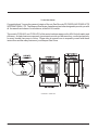
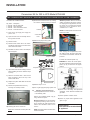
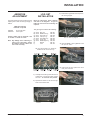
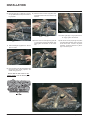
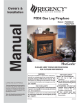
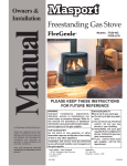
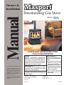
Owners &
Installation
Manual
Freestanding Gas Stove
LISTINGS AND CODE APPROVALS
These gas appliances have been
tested in accordance with AG 103,
NZS 5262 and have been certified by
the Australian Gas Association for
installation and operation as
described in these Installation and
Operating Instructions.
Your unit should be serviced
annually by an authorised service
person.
Models: FG38-NG
FG38-LPG
PLEASE KEEP THESE INSTRUCTIONS
FOR FUTURE REFERENCE
WARNING:
Improper installation, adjustment,
alteration, service or maintenance can
cause injury or property damage. Refer to
this manual. For assistance or additional
information consult an authorised installer,
service agency or the gas supplier.
FOR YOUR SAFETY
Do not store or use gasoline or other
flammable vapours and liquids in the vicinity
of this or any other appliance.
Installation and service must be performed
by an authorised installer, service agency or
the gas supplier.
Head Office - New Zealand
1-37 Mt Wellington Hwy.Panmure,
P.O. Box 14349
Auckland 6.
918-244b
FOR YOUR SAFETY
What to do if you smell gas:
Do not try to light any appliance
Do not touch any electrical
switch: do not use any
phone in your building.
Immediately call your gas
supplier from a neighbour's
phone. Follow the gas supplier's instructions.
If you cannot reach your
gas supplier, call the fire
department.
Australia
P.O. Box 533
Braeside, Victoria, 3195
06/08/05
To the New Owner:
Congratulations! You are the owner of a state-of-the-art Gas Stove by FPI FIREPLACE PRODUCTS
INTERNATIONAL LTD. The Masport Gas Series of appliances has been designed to provide you with
all the warmth and charm of a woodstove, at the flick of a switch.
The models FG38-NG, and FG38-LPG of this series has been approved by AGA for both safety and
efficiency. As it also bears our own mark, it promises to provide you with economy, comfort and security
for many trouble free years to follow. Please take a moment now to acquaint yourself with these
instructions and the many features of your Masport Gas Stove.
FG38-NG & FG38-LPG
2
Masport FG38 FireGenie Freestanding Gas Stove
TABLE OF CONTENTS
Page
Page
Safety Label
Operating Instructions
Specifications ............................................................... 2
Operating Instructions ................................................. 13
Safety Label .................................................................. 4
Lighting Instructions .................................................... 13
Resetting the Unit ....................................................... 13
Installation
General Information ....................................................... 5
Before you start ............................................................ 5
General Safety Information ............................................ 5
Installation Checklist ..................................................... 6
Clearances to Combustibles ......................................... 6
Draft diverter .................................................................. 6
Flueing .......................................................................... 6
Shutdown Instructions ................................................. 13
First Fire ..................................................................... 13
Fan Operation ............................................................. 13
Flame Height Adjustment ............................................ 14
Summary of Controls .................................................. 14
Normal Operating Sounds of Gas Appliances .............. 14
Copy of Lighting Plate Instructions .............................. 15
Maintenance
- Flueing Requirements ............................................... 6
Gas Connection ............................................................ 7
Maintenance Instructions ............................................ 16
Gas Pressure Test ........................................................ 7
Log Replacement ........................................................ 16
S.I.T. Valve Description ................................................. 7
Gold Plated Doors ....................................................... 16
System Data ................................................................. 7
Door and Glass Gasket ............................................... 16
Conversion from NG to LPG .......................................... 8
Glass Replacement ..................................................... 16
Aeration Adjustment ...................................................... 9
Fan Maintenance ........................................................ 17
Log Installation .............................................................. 9
Removing Valve ........................................................... 18
Front Door Installation ................................................. 11
Test for Flue Spillage .................................................. 11
Parts List
Remote Control (optional) ............................................ 12
Final Check ................................................................. 12
Electronic Components ............................................... 19
Wiring Diagram ........................................................... 12
Main Assembly ........................................................... 20
Burner & Log Assembly .............................................. 21
Door Assemblies ......................................................... 22
Warranty
Warranty ..................................................................... 23
Masport FG38 FireGenie Freestanding Gas Stove
3
SAFETY LABEL
This is a copy of the label that accompanies
each Freestanding Gas Stove. We have printed a copy of the contents here for your review.
The safety label is located on the inside of the
drop down pedestal door.
NOTE: Masport units are constantly being improved. Check the label on the unit and if there
is a difference, the label on the unit is the correct
one.
(Australia Only)
4
Masport FG38 FireGenie Freestanding Gas Stove
INSTALLATION
GENERAL
INFORMATION
This installation must conform with local codes
or, in the absence of local codes, with AG 601
(Australia) NZS 5261 (New Zealand).
IMPORTANT:
The FG38 Freestanding Gas Stove must be
installed in accordance with these instructions. Carefully read all the instructions in this
manual first. Consult the "authority having
jurisdiction" to determine the need for a permit
prior to starting the installation.
THIS APPLIANCE SHOULD
BE INSTALLED, REPAIRED,
INSPECTED BEFORE USE
AND CLEANED ANNUALLY
BY AN AUTHORISED SERVICE PERSON. MORE FREQUENT CLEANING MAY BE REQUIRED, DUE TO EXCESSIVE LINT FROM CARPETING, ETC. IT IS
IMPERATIVE THAT CONTROL COMPARTMENT, BURNERS AND CIRCULATING AIR PASSAGEWAYS OF THE APPLIANCE BE KEPT CLEAN.
DUE TO HIGH TEMPERATURES, THE APPLIANCE
SHOULD BE LOCATED OUT
OF TRAFFIC AND AWAY
FROM FURNITURE AND
DRAPERIES.
THIS APPLIANCE CAN ONLY
BE FLUED IN ACCORDANCE
WITH AG 601 OR LOCAL
CODES.
FAILURE TO INSTALL THIS
APPLIANCE CORRECTLY
MAY CAUSE A SERIOUS
HOUSE FIRE.
Provide adequate clearances for servicing,
proper operation and around the air openings
into the combustion chamber. Adequate combustion and ventilation air must also be provided.
The appliance must be installed on a flat, solid,
continuous surface (i.e. wood, metal, concrete). This may be the floor, or it can be raised
up on a platform to enhance its visual impact.
The Masport Freestanding Gas Heater can be
installed in a wide variety of ways and will fit
nearly any room layout. It may be installed in a
recessed position, framed out into the room, or
across a corner.
We recommend that you plan your installation on
paper using exact measurements for clearances and floor protection before actually installing
this appliance. If an existing chimney is not
utilised, position the appliance to allow free
passage of factory-built listed chimney through
the ceiling and roof.
Masport FG38 FireGenie Freestanding Gas Stove
BEFORE YOU START
GENERAL SAFETY
INFORMATION
1) The appliance shall be installed in accordance with the manufacturer's installation
instructions, local gas fitting regulations,
municipal building codes, water supply regulations, electrical wiring regulations, with
AG 601 (AGA gas installation code) NZS
5261 (New Zealand)
INSTALLATION AND REPAIR
SHOULD BE DONE BY AN AUTHORISED SERVICE PERSON. THE APPLIANCE SHOULD BE INSPECTED
BEFORE USE AND CLEANED ANNUALLY BY AN AUTHORISED
SERVICE PERSON. MORE FREQUENT CLEANING MAY BE REQUIRED DUE TO EXCESSIVE LINT
FROM CARPETING, BEDDING MATERIAL, ETC. IT IS IMPERATIVE
THAT CONTROL COMPARTMENTS,
BURNERS AND CIRCULATING AIR
PASSAGEWAYS OF THE APPLIANCE BE KEPT CLEAN.
2) Installation and repair should be done
ONLY by an authorised person.
DUE TO HIGH TEMPERATURES,
THE APPLIANCE SHOULD BE LOCATED OUT OF TRAFFIC AND
AWAY FROM FURNITURE AND DRAPERIES.
5) Inspect the flueing system annually for
blockage and any signs of deterioration.
WARNING: FAILURE TO INSTALL
THIS APPLIANCE CORRECTLY MAY
CAUSE A SERIOUS HOUSE FIRE
AND WILL VOID YOUR WARRANTY.
7) To prevent injury, do not allow anyone who
is unfamiliar with the operation to use the
fireplace.
CHILDREN AND ADULTS SHOULD
BE ALERTED TO THE HAZARDS OF
HIGH SURFACE TEMPERATURES,
ESPECIALLY THE FIREPLACE
GLASS, AND SHOULD STAY AWAY
TO AVOID BURNS OR CLOTHING
IGNITION.
YOUNG CHILDREN SHOULD BE
CAREFULLY SUPERVISED WHEN
THEY ARE IN THE SAME ROOM AS
THE APPLIANCE.
CLOTHING OR OTHER FLAMMABLE MATERIAL SHOULD NOT BE
PLACED ON OR NEAR THE APPLIANCE.
3) See general construction and assembly
instructions. The appliance should be
inspected before use and at least
annually by an authorised service
person. More frequent cleaning may
be required due to excessive lint from
carpeting, bedding material, etc. It is
imperative that control compartments, burners and circulating air passageways of the appliance be kept
clean and free from excessive lint
from carpeting.
4) This appliance must be connected to a flue
and terminate to the outside of the building
envelope. Never flue to another room.
6) Any safety glass removed for servicing
must be replaced prior to operating the
appliance.
8) Wear gloves and safety glasses for protection while doing required maintenance.
9) Under no circumstances should this appliance be modified. Parts that have to be
removed for servicing should be replaced
prior to operating this appliance.
10) Installation and any repairs to this appliance
should be done by an authorised service
person. An authorised service person
should be called to inspect this appliance
annually. Make it a practice to have all of
your gas appliances checked annually.
11) Do not strike the glass door.
12) Under no circumstances should any solid
fuels (wood, paper, cardboard, coal, etc.)
be used in this appliance.
13) The appliance area must be kept clear and
free of combustible materials, (gases and
other flammable vapours and liquids).
5
INSTALLATION
14) This unit can be installed on a solid combustible surface like a wood floor as well as on
carpeting.
CLEARANCES TO
COMBUSTIBLES
Minimum ceiling
height is 36" / 914
mm from top of
unit.
INSTALLATION
CHECKLIST
The clearances listed below are MINIMUM distances. Measure the clearance to both the
appliance and the chimney connector. (The
farthest distance is correct if the two
clearances do not coincide.) For example, if
the appliance is set as indicated in one of the
figures but the connector is too close, move the
stove until the correct clearance to the connector is obtained.
If further reduced
clearances are
needed, obtain requirements for construction of a protected wall from
your local building
authorities and their
allowable reductions of the listed
clearances.
1) Check Clearances to Combustibles, page
6.
2) Install flueing, page 6.
3) Make gas connections, page 7.
4) If necessary, convert NG to LPG on page
8.
5) Test Gas Pressure, page 7.
6) Install log set where indicated on page 9.
7) Install Front Door, page 11.
8) Test for flue spillage (draft test), page 11.
9) Install Remote Control, page 12.
This unit can be installed on a solid combustible
surface like a wood floor. This unit can also be
installed directly on carpeting or vinyl when the
bottom pedestal cover plate (provided with unit)
is installed.
This appliance may be installed only with the
clearances as shown in the situations pictured.
Do not combine clearances from one type of
installation with another in order to achieve
closer clearances.
Use the minimum clearances shown in the
diagrams below for all installations.
10) Final check, page 12.
FG38-NG & FG38-LPG
Clearances
Before leaving this unit with the customer, the
installer must ensure that the appliance is firing
correctly and operation fully explained to customer.
A Side Wall to Unit
7-1/2" / 190 mm
This includes:
B Back Wall to Unit
6" / 155 mm
E Side Wall to Unit
2" / 50 mm
1) Clocking the appliance to ensure the correct firing rate (rate noted on label) after
burning appliance for 15 minutes.
DRAFT DIVERTER
This heater has a draft diverter built in. It must
not be altered, obstructed, or blocked in any
way, and the unit must be installed so that the
draft diverter is in the same atmospheric pressure zone as the combustion air inlet to the
burner. This heater must be properly connected
to a flueing system.
WARNING: Operation of this heater when
not connected to a properly installed and
maintained flueing system can result in
carbon monoxide (CO) poisoning and
possible death.
FLUEING
FG38-NG & FG38-LPG
Reference Dimensions
This heater is a flued appliance and must be
2) If required, adjusting the primary air to
connected to a chimney/flue in accordance
ensure that the flame does not carbon. First
with the installation codes.
allow the unit to burn for 15-20 min. to C Back Wall to Flue Centerline 10-3/4" / 273 mm
stabilize.
Note: The rear pedestal cover plate must
D Side Wall to Flue Centerline 20-1/2" / 520 mm
always be fitted for safety. ElectriCAUTION: Any alteration to the product that F Side Wall to Flue Centerline 11" / 280 mm
cal connections inside.
causes sooting or carboning or that results in
damage is not the responsibility of the manufacturer.
Flueing Requirements
A100 mm diameter flue is required. For cosmetic
or aesthetic purposes 6" outer flue can be used
as long as an approved inner flue is installed.
Fasten but do not penetrate the inner sleeve of
the flue when tightening the screw.
The minimum flue required is 3.3m from
floor level.
Follow all flueing manufacturer’s requirements
and local building codes or AG 601.
6
Masport FG38 FireGenie Freestanding Gas Stove
INSTALLATION
S.I.T. Valve Description
GAS CONNECTION
The gas line should be rigid pipe. Copper may
also be used if approved by AG 601.
The gas connection at the valve is 1/2 male. For
minimum and maximum supply pressure see the
System Data Table.
GAS PIPE PRESSURE
TESTING
The appliance must be isolated from the gas
supply piping system by closing its individual
manual shut-off valve during any pressure
testing of the gas supply piping system at test
pressures equal to or less than 1/2 psig. (3.45
kPa). Disconnect piping from valve at pressures over 3.45 kPa (14" w.c.).
1)
2)
3)
4)
5)
On-Off Solenoid Valve EV1
On-Off Solenoid Valve EV2
Inlet Pressure Test Point
Outlet Pressure Test Point
Connection for Pressure Regulator/Combustion Chamber Compensation
6) Pressure Regulator for Minimum and Maximum Outlet Pressure
7) Gas Outlet Pressure Electric Modulator
8) Pilot Outlet
9) Main Gas Outlet
10) Side Outlet
System Data
FG38
FG38-NG: For 0 to 610 meters altitude
FG38-LPG: For 0 to 610 meters altitude
Burner Inlet Orifice Sizes:
NG
Burner
#33
Max. Input
NG
LPG
38 mj
31 mj
Min. Input
NG
LPG
20.8 mj
16.1 mj
LPG
#52
Supply Pressure
NG
1.13 kPa
LPG
2.75 kPa
The manifold pressure is controlled by a regulator built into the gas control, and should be
checked at the pressure test point.
Manifold Pressure
NG
0.87 kPa
LPG
2.65 kPa
Note:
Electrical: 240 V. 50Hz.
Circulation: High/Off/LO speed fan, 150/89
CFM.
Log Set: Ceramic fiber, 7 per set.
To properly check gas pressure,
both inlet and manifold pressures
should be checked using the valve
pressure ports on the valve.
1) Make sure the valve is in the "OFF" position.
2) Loosen the "IN" (# 3) and/or "OUT" (# 4)
pressure tap(s), turning counterclockwise
with a 1/8" wide flat screwdriver.
3) Attach manometer to "IN" and/or "OUT"
pressure tap(s) using a 5/16" ID hose.
Aeration Setting
NG 15 mm
LPG 6.4 mm
Flue Restrictor Setting
NG Full Open
LPG Full Open
4) Seal and or check the pilot outlet (# 8)
5) The pressure check should be carried out
with the unit burning and the setting should
be within the limits specified on the safety
label.
6) When finished reading manometer, turn off
the gas valve, disconnect the hose and
tighten the screw (clockwise) with a 1/8"
flat screwdriver. Screw should be snug,
but do not over tighten.
Masport FG38 FireGenie Freestanding Gas Stove
7
INSTALLATION
Conversion Kit for NG to LPG Model #756-969
THIS CONVERSION MUST BE DONE BY A QUALIFIED GAS FITTER IF IN DOUBT DO NOT DO THIS CONVERSION !!
Conversion Kit 756-969 Contains:
Qty. Part #
1 904-390
1 908-528
1 908-255
1 918-270
11) Remove the control box cover by undoing
the 3 screws. Maneuver through antenna.
Description
Burner Orifice #52
Red "LPG" label
Label "Converted to LPG"
Instruction Sheet
Antenna
NOTE: The outlet pressure must be set to
minimum 0.74 kPa.
1) Shut off the gas supply and unplug the
power cord.
Control Box
Cover
2) Open the front door and carefully remove
the logs and lava rock.
3) Remove burner.
Minimum pressure: Remove one of the
cables connected to the electric modulator. Keeping the nut (B) blocked, screw in
the screw (C) to increase the pressure
and screw it out to decrease it. Use a
screwdriver 6 x 1 blade.
Cable
Electric
Modulator
12) Remove the jumper using a plier.
4) Remove burner orifice with a 1/2" wrench
and discard. Use a wrench to hold on to the
elbow behind the orifice.
5) Reinstall new burner orifice LPG stamped
#52 and tighten.
After carrying out all adjustments, block
the setting screws with paint, taking care
not to obstruct the breather orifice of the
pressure.
Jumper Location
Put back the modulator plastic cap.
WARNING: To ensure the correct operation of the modulator it is necessary that the
plastic cap (A) is returned to its original
location.
Burner Orifice
Jumper
A
6) Adjust the burner aeration setting to 6.4mm
before installing the burner. Reverse steps
3) and 2).
B
C
7) Stick the conversion label "This unit has
been converted to LPG" over top of the
serial number decal.
8) Replace the yellow "NG" label with the red
"LPG" label.
13) Reverse steps 11 to 9.
9) Remove the pedestal back cover by
removing the 4 Philips screws.
14) Turn on gas supply and plug in power cord.
15)
Adjusting the Outlet Pressure
All the adjustments must be carried out
in the following order:
Remove the modulator plastic cap (A)
using needle nose pliers.
10) Carefully pull out the control box.
NOTE: The control box is held in place with
velcro.
8
Maximum pressure: Turn the unit ON to
its highest input rating. Screw in the nut
(B) to increase the outlet pressure and
screw it out to decrease it. Use a 10 mm
wrench.
NOTE: The outlet pressure must be set to
maximum 2.65 kPa.
16) At the end of all setting and adjustment
operations, check electrical insulation and
gas leaks.
17) Check operation of flame control.
18) Check for proper flame appearance and
glow on logs.
Installer Notice:
These instructions must be left with
the appliance.
Masport FG38 FireGenie Freestanding Gas Stove
INSTALLATION
AERATION
ADJUSTMENT
LOG SET
INSTALLATION
The burner aeration is factory set but may need
adjusting due to either the local gas supply or
altitude.
Read the instructions below carefully
and refer to the diagrams. If logs are
broken do not use the unit until they are
replaced.
3) Place Rear Log A)02-65 on the two pins on
the rear log support.
A)02-65
FG38 with 38 mj NG
FG38 with 31 mj LPG
The gas log kit contains the following:
FG38-NG
FG38-LPG
15 mm Fully Open
6.4 mm open
Caution: Carbon will be produced if the
air shutter is closed too much.
Note: Any damage due to carboning resulting from improperly setting
the aeration controls is NOT covered under warranty.
a)
b)
c)
d)
e)
f)
g)
h)
i)
02-65
02-56
02-44
02-46
02-45
02-47
02-48
Rear Log
Middle Left Log
Front Left Log
Left Top Log
Front Right Log
Center Log
Middle Right Log
Embers
Lava
902-267
902-230
902-228
902-231
902-229
902-232
902-226
902-151
902-154
Pins on Rear Log Support
4) Place the Middle Left Log B)02-56 on the
two pins as shown.
The "02" refer numbers (i.e. 02-65) are
molded into the rear of each log.
B)02-56
5) Place Front Left Log C)02-44 onto the 2
front pins as shown.
1) Carefully remove the logs from the box and
unwrap them. The logs are fragile, handle
with care - do not force into position.
C)02-44
2) Sprinkle the embers on the left and right
sides of the firebox base.
Embers
Masport FG38 FireGenie Freestanding Gas Stove
Embers
9
INSTALLATION
6) Place the Left Top Log D)02-46 on the pin
on Log B)02-56 and on top of the cutout on
Log A)02-65.
9) Place the notch in Center Log F)02-47 over
Log E)02-45 and across the cutout on Log
A)02-65.
G)02-48
E)02-45
A)02-65
F)02-47
A)02-65
D)02-46
Side View
E)02-45
B)02-56
Bracket
C)02-44
Notch
Pin
Cutout
7) Place Front Right Log E)02-45 on the two
pins as shown.
The bottom right edge of Log G)02-48 must
sit snugly against the bracket
Cutout
10) Position notch in Front Right Log G)02-48
on Log F)02-47 and push the bottom right
edge against the bracket on the burner
tray.
11) Test fire to ensure proper light off (make
sure flame flows smoothly from one end of
burner to the other. If there is any flame
hesitation, check that area for any blockage of the burner port.
G)02-48
A)02-65
-47
E)02-45
F)02
E)02-45
8) Place the lava rock in the area between the
left and right logs, leaving a space in the
middle for log (F) 02-47.
Notch
Ensure that the lava rocks are not
placed directly over the burner ports.
6
A)02-65
B)02-56
C)02-44
10
)0
2-
48
F)0
2-4
7
D)
02
-4
G
E)02-45
Masport FG38 FireGenie Freestanding Gas Stove
INSTALLATION
FRONT DOOR
INSTALLATION
1) Open the two side panels.
2) Slide the door onto the two hinge pins
making sure the two pieces are flush together. See diagram 1.
6) Test the seal around the door by placing a
piece of paper between the unit and the
door, close the door and try to pull the paper
out. If it slips out easily, then the door is not
properly sealed. Tighten or loosen the latch.
See diagram 3.
Note:
The smoke should be drawn into the draft
diverter. If the smoke is not drawn into the draft
diverter, turn the unit off and check for the
cause of lack of draft.
.
The door latch may require adjustment as the door gasket material compresses after a few fires
and after glass replacement. Turn
the latch catch inward or outward to loosen or tighten.
Note: If the flue is blocked or has a strong
reverse flow, check for the cause of the
lack of draft.
Diagram 3
Diagram 1
3) Close the door. The latch plate must be
centered around the alignment pin. See
diagram 2. If the latch plate interferes with
the corner of the stove you may want to
angle the plate slightly so the door closes
easier.
TEST FOR FLUE
SPILLAGE
A "spillage" test must be made before the
installed unit is left with the customer. Follow
the procedure below:
1) Start all exhaust fans in the home and any
other gas appliances. Then close all doors
and windows.
2) Light the unit and set controls to maximum.
3) After five minutes, test that there is a "pull"
on the flue by placing a smoke match,
cigarette or similar device which gives off
smoke, on the edge of the draft diverter.
See diagrams.
Diagram 2
4) The latches should already be at the proper
setting. If they are too hard or too easy to
close, you may want to adjust them by
loosening the latch catch. See diagram 3.
5) Remove the blue plastic protective coating
from the glass.
Masport FG38 FireGenie Freestanding Gas Stove
11
INSTALLATION
REMOTE CONTROL
FINAL CHECK
Use the Masport Remote Control Kit approved
for this unit. Use of other systems may void your
warranty.
Before leaving this unit with the customer, the
installer must ensure that the appliance is firing
correctly. This includes:
The remote control kit comes with a hand held
transmitter and a wall mounting plate.
1) Clocking the appliance to ensure the correct firing rate (rate noted on label) at 15
minutes.
1) Choose a convenient location to mount the
hand held transmitter, protection from extreme heat is very important.
2) If required, adjusting the primary air to
ensure that the flame does not carbon. First
allow the unit to burn for 15 min. to stabilize.
By usiing the wall mounting plate to house the
transmitter, the remote can also be used as a
wall thermostat.
3) Check for proper draft.
CAUTION
Any alteration to the product that
causes sooting or carboning that
results in damage to the exterior
facia is not the responsibility of the
manufacturer.
WIRING
Caution: Ensure that the wires do not
touch any hot surfaces and are away
from sharp edges.
WARNING:
Electrical Grounding Instructions
This appliance is equipped with a three
pronged (grounding) plug for your protection against shock hazard and
should be plugged directly into a properly grounded three-prong receptacle.
Do not cut or remove the grounding
prong from this plug.
12
CAUTION:
Label all wires prior to disconnection
when servicing controls.
Wiring errors can cause improper
and dangerous operation.
Masport FG38 FireGenie Freestanding Gas Stove
OPERATING INSTRUCTIONS
RESETTING
THE UNIT
OPERATING
INSTRUCTIONS
Before operating this appliance, proceed
through the following check list.
1) Read and understand these Instructions
before operating this appliance.
2) Check to see that all wiring is correct and
enclosed to prevent possible shock.
3) Check to ensure there are no gas leaks.
1) Open the pedestal door on the unit.
2) Press and release the reset button, located
on the unit's control panel once.
3) Wait for approximately 8 seconds and the
pilot sparks can be heard and seen. It would
take 2 to 3 seconds for the flame to be lit.
Set the fan speed on the control panel at the top
rear of the unit to adjust to the desired speed.
Pressing and releasing the plus (+) FAN button
will change the fan speed as follows:
OFF -> LOW -> MEDIUM -> HIGH -> OFF, etc.
Pressing and releasing the minus (-) FAN
button will be the reverse of the above.
NOTE: A period of 30 seconds must pass
before another reset is attempted.
4) Make sure the three pieces of door glass
are properly positioned. Never operate the
appliance with any of the glass removed or
with the door open.
SHUTDOWN
INSTRUCTIONS
5) Verify that all flueing and the cap is unobstructed.
6) Verify log placement.
FAN OPERATION
1) Press the ON/OFF switch once.
2) The LED will flash.
LIGHTING
INSTRUCTIONS
3) Turn off all electric power to the appliance
if service is to be performed.
FIRST FIRE
1) Plug the power cord into a power outlet.
2) Press and release the ON/OFF switch once
to start the unit. The LED will be lit.
3) After approximately 8 seconds the spark
ignition system will spark for 8 seconds to
light the main burner.
4) If the main burner does not light, reset the
unit.
The FIRST FIRE in your heater is part of the paint
curing process. To ensure that the paint is
properly cured, it is recommended that you
burn your fireplace for at least four (4) hours
the first time you use it with the fan on.
When first operated, the unit will release an
odour caused by the curing of the paint and the
burning off of any oils remaining from manufacturing. Smoke detectors in the house may go off
at this time. Open a few windows to ventilate
the room for a couple of hours. The glass may
require cleaning.
NOTE: The main burner will always start on
"HIGH" and resume it's last setting after
20 seconds of operation.
NOTE: When the glass is cold and the appliance is lit, it may cause condensation
and fog the glass. This condensation is
normal and will disappear in a few
minutes as the glass heats up.
DO NOT ATTEMPT TO CLEAN THE GLASS
WHILE IT IS STILL HOT!
DO NOT BURN THE APPLIANCE WITHOUT THE GLASS FRONT IN PLACE.
Masport FG38 FireGenie Freestanding Gas Stove
13
OPERATING INSTRUCTIONS
ADJUSTING FLAME
HEIGHT
SUMMARY OF
CONTROLS
There are six flame settings that can be adjusted by pressing and releasing the plus (+) and
minus (-) FLAME button.
On/Off Button
If the unit is switched off, pressing and releasing this button once will switch the unit on. The
unit will resume its last settings.
The FLAME setting button is located on the
control panel at the top rear of the unit.
If the unit is switched on, pressing and releasing this button once will switch the unit off.
Flame:
Increase - If the unit is switched on, pressing
and releasing the flame plus (+) button once will
increase the flame height to the next available
high setting.
Decrease - If the unit is switched on, pressing
and releasing the flame minus (-) button once
will decrease the flame height to the next
available low setting.
Fan:
Increase - If the unit is switched on, pressing
and releasing the fan plus (+) button once will
increase the fan speed to the next available
high setting.
Decrease - If the unit is switched on, pressing
and releasing the fan minus (-) button once will
decrease the fan speed to the next available
low setting.
NORMAL OPERATING
SOUNDS OF
GAS APPLIANCES
It is possible that you will hear some sounds
from your gas appliance. This is perfectly normal due to the fact that there are various gauges
and types of steel used within your appliance.
Listed below are some examples. All are normal operating sounds and should not be
considered as defects in your appliance.
Blower:
Masport gas appliances use high tech blowers
to push heated air farther into the room. It is not
unusual for the fan to make a "whirring" sound
when ON. This sound will increase or decrease
in volume depending on the speed setting of
your fan speed control.
Burner Tray:
The burner tray is positioned directly under the
burner tube(s) and logs and is made of a
different gauge material from the rest of the
firebox and body. Therefore, the varying thicknesses of steel will expand and contract at
slightly different rates which can cause "ticking" and "cracking" sounds. You should also be
aware that as there are temperature changes
within the unit these sounds will likely re-occur.
Again, this is normal for steel fireboxes.
Gas Control Valve:
As the gas control valve turns ON and OFF, a
dull clicking sound may be audible, this is normal
operation of a gas regulator or valve.
WARNING
DO NOT SPRAY AEROSOLS IN
THE VICINITY OF THIS
APPLIANCE WHILE IN
OPERATION
14
Unit Body/Firebox:
Different types and thicknesses of steel will
expand and contract at different rates resulting
in some "cracking" and "ticking" sounds will be
heard throughout the cycling process.
Masport FG38 FireGenie Freestanding Gas Stove
OPERATING INSTRUCTIONS
COPY OF THE LIGHTING PLATE INSTRUCTIONS
FOR YOUR SAFETY READ BEFORE LIGHTING
This appliance must be installed in accordance with local codes, if any; if not,
follow the current CAN1-B149/ANSI Z 223.1 (Australia: AG601, New Zealand: NZS 5261)
WARNING: If you do not follow these instructions exactly, a fire or explosion may result
causing property damage, personal injury or loss of life. Improper installation, adjustment,
alteration, service or maintenance can cause injury or property damage. Refer to the
owner’s information manual provided with this appliance. For assistance or additional
information consult a qualified installer, service agency or gas supplier.
A) BEFORE LIGHTING smell all around the appliance
area for gas. Be sure to smell next to the floor
because some gas is heavier than air and will
settle on the floor.
WHAT TO DO IF YOU SMELL GAS
- Do not try to light any appliance
- Do not touch any electric switch, do not use any
phone in your building
- Immediately call your gas supplier from a
neighbors phone. Follow the gas supplier’s instructions.
- If you cannot reach your gas supplier, call the
fire department.
B) Do not use this appliance if any part has been
under water. Immediately call a qualified service
technician to inspect the appliance and to replace
any part of the control system and any gas control
which has been under water.
This appliance needs fresh air for safe operation
and must be installed so there are provisions for
adequate combustion and ventilation air.
CAUTION: Hot while in operation. Do not touch. Severe Burns may result. Due to high surface
temperatures keep children, clothing and furniture, gasoline and other liquids having
fammable vapors away. Keep burner and control compartment clean. See installation and
operating instructions accompanying appliance.
LIGHTING INSTRUCTIONS
STOP! Read the safety information above on this label.
1)
Plug the power cord into a power outlet.
2)
Press and release the ON/OFF switch once to
start the unit. The LED will be lit.
3)
After approximately 8 seconds the spark
ignition system will spark for 8 seconds to
light the main burner.
4)
If the main burner does not light, reset the
unit.
TO TURN OFF GAS APPLIANCE
1)
Press the ON/OFF switch once.
2)
The LED will flash.
3)
Turn off all electric power to the unit if
service is to be performed.
You may shut off the pilot during prolonged non use periods to conserve fuel.
DO NOT REMOVE THIS INSTRUCTION PLATE
918-247
WARNING:
DO NOT SPRAY AEROSOLS IN THE VICINITY OF
THIS APPLIANCE WHILE IN OPERATION.
Masport FG38 FireGenie Freestanding Gas Stove
15
MAINTENANCE
MAINTENANCE
INSTRUCTIONS
Any maintenance required accessing the
glass door of the unit must be performed by
an authorized service person.
1) Always unplug the power cord before
cleaning. For relighting, refer to lighting
instructions. Keep the burner and control
compartment clean by brushing and vacuuming at least once a year. When cleaning
the logs, use a soft clean brush as the logs
are fragile and easily damaged.
2) Clean glass (never when unit is hot), appliance, louvres, and door with a damp
cloth. Never use an abrasive cleaner. The
gold louvres (and optional gold door) may
be scratched if abrasives are used to
clean them.
The heater is finished in a heat resistant
paint and should only be refinished with
heat resistant paint (not with wall paint).
Masport uses StoveBright Paint - Metallic
Black #6309.
3) Make a periodic check of burner for proper
position and condition. Visually check the
flame of the burner periodically, making
sure the flames are steady; not lifting or
floating. If there is a problem, call an authorized service person.
4) The appliance and flueing system must be
inspected before use, and at least annually, by an authorized field service person,
to ensure that the flow of combustion and
ventilation air is not obstructed.
During the annual service call, the burners
should be removed from the burner tray
and cleaned. Replace the embers - do not
block the burner ports.
5) Keep the area near the appliance clear and
free from combustible materials, gasoline
and other flammable vapours and liquids.
WARNING: CHILDREN AND
ADULTS SHOULD BE ALERTED TO
THE HAZARDS OF HIGH SURFACE
TEMPERATURE AND SHOULD
STAY AWAY TO AVOID BURNS OR
CLOTHING IGNITION. YOUNG
CHILDREN SHOULD BE CAREFULLY SUPERVISED WHEN THEY ARE
IN THE SAME ROOM AS THE APPLIANCE.
16
GLASS
REPLACEMENT
CAUTION: ANY SAFETY SCREEN
OR GUARD REMOVED FOR SERVICING AN APPLIANCE MUST BE
REPLACED PRIOR TO OPERATING THE APPLIANCE.
Your Masport heater is supplied with high
temperature, 5mm Neoceram silica coated ceramic glass that will withstand the highest heat
that your unit will produce. In the event that you
break your glass, purchase your replacement
from an authorized Masport dealer only, and
follow the step-by-step instructions for replacement.
CLOTHING OR OTHER FLAMMABLE MATERIAL SHOULD NOT BE
PLACED ON OR NEAR THE APPLIANCE.
Removing Glass:
DO NOT USE THIS APPLIANCE IF
ANY PART HAS BEEN UNDER
WATER. IMMEDIATELY CALL AN
AUTHORIZED SERVICE TECHNI
CIAN TO INSPECT THE APPLIANCE AND TO REPLACE ANY PART
OF CONTROL SYSTEM AND ANY
GAS CONTROL WHICH HAS BEEN
UNDER WATER.
Note: Wearing gloves will protect your
hands while handling glass.
1) Remove the door from the unit and place on
a soft surface to prevent scratching.
2) Pull out the door gasket.
3) Remove the 24 nuts holding the glass
retainers in place. Do not remove the nuts
underneath the retainers.
6) Verify proper operation after servicing.
4) Remove the door catch plate.
LOG REPLACEMENT
The unit should never be used with broken logs.
Unplug the power cord and allow the unit to cool
before opening door to carefully remove the
logs. If for any reason a log should need
replacement, you must use the proper replacement log. The position of these logs must be as
shown in the diagram under Log Installation.
Note:
5) Remove glass retainers on sides first (3
each side) then remove two center retainers.
Note: Center glass retainers are glued
to center glass.
6) Remove glass from aluminium extrusions.
When removing center glass, leave white
insulation in place.
Improper positioning of logs may
create carbon build-up and will
alter the unit’s performance
which is not covered under warranty.
DOOR AND GLASS
GASKET
If the door gasket requires replacement use
7/8" diameter oval door gasket (Part # 650920). The glass requires 5/8" flat glass gasket.
See your Masport dealer.
GOLD-PLATED DOORS
The 24 carat gold plated finish on the door
requires little maintenance, and need only be
cleaned with a damp cloth. DO NOT use
abrasive materials or chemical cleaners, as
they may harm the finish and will void the
warranty. Clean any fingerprints off before
turning the unit on.
Safety Screen: Only required in Australia
Masport FG38 FireGenie Freestanding Gas Stove
MAINTENANCE
Installing Glass:
1) Install both center and side glass onto
aluminium extrusions as per diagram.
FAN MAINTENANCE
If your fan requires maintenance or replacement, access to the fan is through the access
panel on the rear wall of the firebox.
If the unit is damaged or needs repair, it shall be
repaired by the manufacturer or its service
agent or similiarly qualified person in order to
avoid a hazard.
Note: The unit MUST NOT be operated
without the fan access panel securely in place and correctly
sealed.
To Remove FG38 Fan:
1) Unplug or disconnect power source to
stove.
2) Remove all logs and the rear log support,
then remove the 10 screws holding the
access panel in place, see Diagram 1. (Fan
is also accessible by opening the right side
door. See Diagram 2).
3) Unclip the black, red and white wires from
the fan motor.
IMPORTANT
Disconnect power supply
before servicing
2) Place glass assembly into door frame.
3) Install retainers by placing 1 drop of glue
where previously glued and put in place.
4) Install side retainers.
5) Install door catch plate.
6) Install the 24 nuts loosely, do not tighten yet.
7) Tighten side panels nuts using the following procedure:
a. tighten top & bottom outside corner nuts
(2)
b. tighten inside nuts (3)
c. tighten top & bottom inside corners (2)
8) Tighten the 10 nuts on center glass retainer.
9) Repeat step 7 for other side panel.
10) Replace new gasket by gluing it in place.
IMPORTANT: These fans collect a
lot of dust from within your home.
Ensure you maintain these fan motors on a regular basis by vacuuming out the fan squirrel cages, around
the motor, and around the grills on
the back of the stove.
WARNING: Electrical Grounding Instructions This appliance is
equipped with a three pronged
(grounding) plug for your protection against shock hazard and
should be plugged directly into a
properly grounded three-prong receptacle. Do not cut or remove the
grounding prong from this plug.
Diagram 1
4) Lift fan off of the 2 pins, tip back and pull
through firebox opening. Disconnect the
green ground wire from the left side of the
fan as soon as you can reach it.
11) Install door onto stove and check the seal.
Diagram 2
Replacing FG38 Fan:
Reverse the above steps (1 to 4). If necessary
install a new gasket before replacing the fan
access panel. Make sure the fan wires and the
ground wire are reattached.
Masport FG38 FireGenie Freestanding Gas Stove
17
MAINTENANCE
REMOVING VALVE
If your valve requires maintenance or replacement, follow these instructions:
4) Remove the two outside frame pieces by
removing two screws per side. See diagram below.
NOTE: Always shut off the gas and disconnect the power supply before
removing the valve.
7) At this point you should disconnect the gas
at the valve.
8) Remove the pedestal back cover by removing the 4 Philips screws.
9) Disconnect the ground wires.
1) Open the front door and carefully remove
the logs and lava rock.
2) Remove the burner by removing the two
1/4" hex head screws. See diagram below.
5) Open the side pedestal door by unscrewing
the 2 Philips screws.
6) Disconnect the valve wires from the 9 pin
connector, located on the right side of the
connector.
3) Open the front pedestal door and unhook
chain. You may want to put a soft cloth on
the base of the unit so that when the
pedestal door is open it doesn't scratch the
paint. See diagram below.
Ground
Wires
10) Remove the eight 1/4" hex head screws
holding the burner tray assembly in place.
11) Carefully lift the burner tray assembly out.
Valve wires consist of 2 orange, 1 yellow
and 2 purple colored wires.
12) To replace the burner tray assembly, simply reverse these instructions.
9 Pin
Connector
18
Masport FG38 FireGenie Freestanding Gas Stove
PARTS LIST
ELECTRONIC COMPONENTS PARTS LIST
910-915
910-082
910-089
910-088
910-912
910-084
910-526
910-080
910-906 910-083 910-514
910-916
910-521, 910-522, 910-523
FG37
FG38
FG39
PG33
PG36
HG35
PG121/PG131
N/A
N/A
N/A
N/A
N/A
910-909 Fan Resistor
910-915 Intermittent Pilot
910-082 Direct Spark Ignitor
N/A
N/A
910-089 Flame Cable
910-088 Spark Cable
910-084 Control Box
910-526 Manual Control
N/A
N/A
N/A
910-080 Valve
910-521 Control Box Cable (1)
910-522 Control Box Cable (2)
910-523 Control Box Cable (3)
(2)
910-912 Ignition Module to Valve Cable
N/A
(1)
910-514 Jumper
(2)
(2)
(2)
(3)
N/A
N/A
N/A
910-906 Reset Switch
910-083 Ignition Module (1)
910-916 Ignition Module (2)
N/A*
(1)
(2)
(2)
(2)
(2)
(2)
(2)
N/A
* Note: The Control Box Cable wires for the FG38 come separately: 910-502, 910-505, 910-506, 910-507, 910-509
Masport FG38 FireGenie Freestanding Gas Stove
19
PARTS LIST
FG38 MAIN ASSEMBLY
Part #
1) 560-920
560-922
2) 750-532
9) 750-040
10) 750-074
Description
Top / Bottom Gold Louvre (Set)
Top / Bottom Black Louvre (Set)
Safety Screen (Australia only)
Fan Access Door
Gasket for Fan Access Door
560-519/P
11) 910-169/P
12) 910-714
Fan Assembly
Fan Motor (240 Volt)
Power Cord (240 Volt)
15)
16)
17)
18)
Pedestal Assembly
Pedestal Door
Pedestal Door Magnet
Pedestal Back
*
730-039
904-257
750-084
19) 756-518
20) 756-520
21) 560-031
20
Side Panel Door Assy (Right Side)
Side Panel Door Assy (Left Side)
Hinge for Side Panel
Part #
23)
24)
25)
30)
32)
33)
34)
35)
38)
46)
Description
904-258
948-255
750-095
750-026
730-028
560-535
590-273
590-930
820-058F
750-083
910-087
Side Panel Door Magnet
Door Latch c/w Hook
Door Hold Down Bracket
Rear Panel
Firebox Baffle
False Top Assembly
Flue Attachment Bracket
Ult. 6" Flue Collar (Optional)
Pedestal Base Cover
Rear Control Panel
Switch Manual Control ECS c/w Wire Harness
756-969
948-217
918-244
Conversion Kit - to LPG
Logo Plate
Manual
*Not available as a replacement part.
Masport FG38 FireGenie Freestanding Gas Stove
PARTS LIST
FG38 BURNER & LOG ASSEMBLY
Part #
Description
756-527/P
756-529/P
60) 910-080
910-081
904-689
904-390
Valve Assembly - NG
Valve Assembly - LPG
Valve Sigma 845 - NG
Valve Sigma 845 - LPG
#33 Orifice - NG at 38 mj.
#52 Orifice - LPG at 31 mj.
71)
72)
75)
78)
752-528
910-082
730-935
752-550
Rear Log Bracket Assy
Ignition Direct Spark Assy. - NG/LPG
Log Set
Burner Assy - NG/LPG
910-083
910-084
910-088
910-089
910-906
910-086
Module Sit 230V
Control Box ECS
Wire ECS Module Spark (Red)
Wire ECS Module Flame (Red
Switch Push Button Reset ECS
Remote Control - ECS (optional)
902-267
902-231
902-232
902-226
902-230
902-229
902-228
Rear Log
Left Top Log
Center Log
Middle Right Log
Middle Left Log
Front Right Log
Front Left Log
92)
93)
94)
95)
96)
97)
98)
*Not available as a replacement part.
Masport FG38 FireGenie Freestanding Gas Stove
21
PARTS LIST
FG38 DOOR ASSEMBLIES
Part #
101)
105)
106)
107)
108)
111)
112)
208)
730-924
730-926
730-932
730-928
650-920
*
940-323/P
936-243
940-322/P
*
750-015
940-325/P
Description
Gold Mitred Door - Complete
Black Mitred Door - Complete
Gold Wrap Door - Complete
Gold Panel Door - Complete
Door Gasket Kit
Ceramic Paper
Side Glass
Glass Gasket
Centre Glass
Door Frame Fibre Paper
Door Glass Extrusion
Wrap Glass
*Not available as a replacement part.
22
Masport FG38 FireGenie Freestanding Gas Stove
WARRANTY
THE MASPORT EXPRESS WARRANTY
All new Masport Gas appliances are warranted, subject to the
following conditions, to be free from defects in material or
workmanship under normal use. The Express Warranty on all
parts, including firebox components but excluding fans, flues
and flue accessories is two years from date of original
purchase as well as labour costs involved in the repair or
replacement. The Express Warranty on fans, flues and accessories is for a period of twelve months from date of original
purchase and includes labour costs involved in the repair or
replacement.
This Express Warranty Does Not Cover:
1. Defects, malfunctions or failures caused by incorrect installation, normal wear and tear, misuse, neglect, accidental damage or failure to follow the fuel selection, product operating and
maintenance instructions, or resulting from installations, repairs or modifications to the equipment carried out by unauthorised persons.
2. Defects, malfunctions or failures caused by an act or omission
of other persons after the product has left Masport's control.
3. The costs of collection and delivery of the equipment.
This Express Warranty applies only with respect to defects in
material and workmanship under normal and proper use of
the NEW UNIT in its unmodified condition. Masport's obligation under this Express Warranty is limited to the repair or
replacement, at its option, by an approved Masport Gas
Service Agent (Retailer) of any part found to be defective in
material or workmanship.
Labour costs involved in the repair or replacement are also
covered under this Express Warranty as per the time condition
outlined.
If an approved Masport Gas Service Agent is requested to
attend on a service call that is not covered under this Express
Warranty, a call out charge may be applicable, regardless of
whether a repair is carried out or not.
Masport can accept no obligation whatsoever for any incidental, consequential or special damages or expenses resulting
from any product defect. This Express Warranty applies from
the date of original purchase, applies to the original purchaser, and is not transferable. The decision to repair or replace
defective components will be made by Masport or its agent
and actioned by an approved Masport Service Agent.
4. The cost of labour or materials as a consequence of faulty
installation of gas supply line, flue, burner or log settings, or
non-compliance with local codes.
The Express Warranty is not intended to exclude any rights the
purchaser may have under the laws of the place, state, or
country of purchase. Nothing in this Express Warranty limits or
restricts any other statutory right or remedy available to the
purchaser.
How You Obtain Warranty Service:
Provide proof of the date of purchase. Should the need for a
warranty claim arise reasonable proof of the purchase date is
required therefore you should retain your sales receipt. Where
flueless appliances are not permanently installed, they should be
returned to a Service Agent for evaluation.
Make the faulty part(s) available for inspection by Masport and/or
its agents so that the validity of the claim can be established by
them.
Australia Distributor:
New Zealand:
Masport Pty Limited
P.O. Box 533
Braeside Victoria 3195
Masport Limited
P.O. Box 14-349
Panmure
Auckland 6
For your own records, please complete the following:
Model: ________________________________________ Serial Number: ____________________________
Retailer: ________________________________________________________________________________
______________________________________________________________________________________
Purchase Date: _______________________________
Masport FG38 FireGenie Freestanding Gas Stove
23
© Copyright 2005, FPI Fireplace Products International Ltd. All rights reserved.
Printed in Canada