1
INSTALLATION, OPERATION
AND MAINTENANCE MANUAL
FOR
DJM3
MODEL 3.2 and 3.3
Modulating Burner Control
INDOOR AND OUTDOOR MODELS
UNIT MODEL NO. ____________________________
UNIT SERIAL NO. ____________________________
SERVICED BY _______________________________
TEL. NO: ___________________________________
CANADIAN HEAD
OFFICE AND
FACTORY
1401 – HASTING CRES. SE
CALGARY, ALBERTA
T2G 4C8
USA
HEAD OFFICE AND
FACTORY
rd
32050 W. 83 ST.
DESOTO, KANSAS
66108
CANADIAN
EASTERN FACTORY
1175–TWINNEY DRIVE
NEWMARKET, ONTARIO
L3Y 5V7
SALES OFFICES ACROSS CANADA AND USA
RETAIN INSTRUCTIONS WITH UNIT AND MAINTAIN IN A LEGIBLE CONDITION
PLEASE GIVE MODEL NO. & SERIAL NO. WHEN CONTACTING
FACTORY FOR INFORMATION AND/OR PARTS.
FORM #DJM3 03/01
DJM3.2 MANUAL
TABLE OF CONTENTS
Page
I.
II.
III.
APPLICATION ............................................................................................................ 1
SERVICE..................................................................................................................... 1
GENERAL DESCRIPTION ......................................................................................... 1
Basic Features ..................................................................................................................................2
IV.
V.
WIRING ....................................................................................................................... 3
OVERVIEW OF DJM OPERATION ............................................................................ 3
Supply Fan Operation ......................................................................................................................3
Damper Operation ............................................................................................................................3
VI. SYSTEM TIMINGS...................................................................................................... 5
VII. DIPSWITCHES ........................................................................................................... 5
Switches ............................................................................................................................................5
VIII. POTS .......................................................................................................................... 5
Main Board Pots Located on the Right Side of the DJM3.2 and 3.3 ...........................................6
IX.
STATUS LIGHTS........................................................................................................ 6
LED 1 .................................................................................................................................................6
LED 2 .................................................................................................................................................6
LED 3 .................................................................................................................................................7
LED 4 .................................................................................................................................................7
X.
AUTO BYPASS LOW LIMIT....................................................................................... 7
Resetting Low Limit .........................................................................................................................8
XI.
DAY AND NIGHT OPERATING STRATEGIES.......................................................... 8
Blower/Damper Operation ...............................................................................................................8
Day and Night Operating Strategies...............................................................................................8
XXX = Switch (SW.) can be "ON" or "OFF" ....................................................................................................... 8
Day Mode General Heat/Blower Operation ....................................................................................8
Night Mode General Heat/Blower Operation .................................................................................9
XII. BASIC BURNER OPERATION................................................................................. 10
XIII. TEMPERATURE CONTROL – GENERAL OVERVIEW........................................... 10
XIV. MASTER SET-POINT ............................................................................................... 10
The Optional Reset Inputs.............................................................................................................11
Night Heat........................................................................................................................................11
XV. INDUCED VOLTAGE ON REMOTE CONTROL WIRING ........................................ 11
XVI. NIGHT HEAT THERMOSTATS ................................................................................ 11
Modulating Room Thermostat For Night Heat ............................................................................11
Make/Break Night Heat Thermostats............................................................................................12
XVII. ROOM RESET THERMOSTAT OPTIONS ............................................................... 12
Modulating Room Reset (continuous blower operation only).............................................. 12
ROOM RESET AUTHORITY TABLE ..............................................................................................13
Multiple Room Sensors .................................................................................................................15
BMS Reset (continuous blower only)................................................................................... 15
BMS RESET FROM VOLTAGE APPLIED TO + AND Β ................................................................16
Page i
Revised: 03/11/99
DJM3.2 MANUAL
TABLE OF CONTENTS
Page
BMS Calibration..............................................................................................................................16
Ambient Reset (continuous blower operation only).............................................................. 16
Make/Break Resets and Overrides ...............................................................................................17
XVIII. CALCULATED SET-POINT READOUT (Base Plus Calculated)............................ 22
SET-POINT READOUT AND DISCHARGE TEMPERATURE FROM VOLTAGE ON
READOUT PINS (diagram follows)..................................................................................... 23
XIX. DISCHARGE TEMPERATURE READOUT .............................................................. 23
XX. DISCHARGE/ROOM SENSOR READOUTS, CALIBRATION, ETC........................ 24
TE 6000 Discharge Sensor Self-Test ............................................................................................24
TE 6100 Resistances......................................................................................................................24
Sensor Resistance Chart for TE 6100-960 and TE 6000-960......................................................24
Discharge Sensor Calibration .......................................................................................................25
TEMPERATURE READOUT FROM VOLTAGE ON READOUT PINS (See diagram Page 23)........25
Discharge Set-Point Calibration ...................................................................................................25
Johnson Set Point While Set at 21°C ...........................................................................................26
Built In Set-Point.............................................................................................................................26
For either of the above: .................................................................................................................26
Room Sensor Calibration ..............................................................................................................26
BMS Calibration and Set Up..........................................................................................................26
XXI. DJM3.2 SET UP SHEET MAY 7, 1998 .................................................................... 27
Blower/Damper Operation .............................................................................................................28
XXII. BURNER SET UP ..................................................................................................... 28
Manual Service Switch...................................................................................................................28
Manual Firing Set Up Pot...............................................................................................................28
Important Usage Notes Regarding the Service Pot ....................................................................28
Burner Selection.............................................................................................................................28
Combustion Set Up ........................................................................................................................29
The Standard (or Round) Burner ....................................................................................................29
For Either Burner............................................................................................................................29
High Turndown (Rectangular) Burner ............................................................................................30
Top Loading ....................................................................................................................................30
5.CURVE MATCHING PROCEDURE .............................................................................................31
Pilot Set Up (high turndown).............................................................................................................32
Standard (Round) Burner................................................................................................................32
Propane Gas ...................................................................................................................................34
Inlet/Manifold Pressure Settings...................................................................................................34
XXIII.
SPECIAL SERVICE NOTES ............................................................................... 34
On Board Fuse................................................................................................................................34
Resetting Low Limit, Bad Sensor, Flame Failure Lockout.........................................................34
Low Limit Lockouts........................................................................................................................35
What happens if ignition fails on morning start-up?..................................................................35
Two Speed VAV Applications or High Limit Tripping.................................................................36
Checking Speed Sensor with the Fluke 80 Series Meter............................................................36
Page ii
Revised: 03/11/99
DJM3.2 MANUAL
TABLE OF CONTENTS
Page
Speed Sensor Values.....................................................................................................................37
Pre-purge Light Coming On (when not supposed to)........................................................................37
Constant Purge Light, No Ignition Attempt .................................................................................37
Failed Operation or Solid State Control Contacts by Others ....................................................37
S/A Fan Off Before Room Satisfied in Night Heat Mode ............................................................37
Resolution .......................................................................................................................................38
Air Balancing - Refer to next item......................................................................................................38
Discharge Temperature in Cold Weather.....................................................................................38
Ignition Problems ...........................................................................................................................38
Regulator Gas Pressure Responses ............................................................................................39
Pilot Sensing Problems .................................................................................................................39
DJM3.2 Locks Up on Trial for Ignition..........................................................................................40
Rumble During Light Off................................................................................................................40
Combustion Fan Motor Surging in Speed ...................................................................................40
Modulating Valve Will Not Respond to Signal to Open ..............................................................41
Improper Burning ...........................................................................................................................41
Sooting Burner/Heat Exchanger ...................................................................................................41
Smell From Flue (Products of Combustion) .......................................................................................41
Water and Ice From Combustion ..................................................................................................42
Burner Pulsing, Backfiring, Exploding, Noisy.............................................................................42
Fire Without Combustion Fan .......................................................................................................42
Replacement of Combustion Fan Motors ....................................................................................42
Set Up When Replacing DJM3.2 in Field......................................................................................42
Side Wall Venting ...........................................................................................................................43
Main Gas Valve Over Travel Switch (Option) ................................................................................43
Simulating a Heat Call....................................................................................................................43
XXIV.
MISCELLANEOUS NOTES................................................................................. 43
Combustion Blower Speeds..........................................................................................................43
Maxitrol Modulating Gas Valve Voltages .....................................................................................44
XXV.
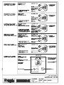
VALVE DRAWINGS ............................................................................................ 44
Page iii
Revised: 03/11/99
A
DJM3.2 MANUAL
MODEL DJM3.2 and 3.3
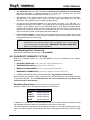
If you note errors or omissions, please contact Wade Pascoe at (403) 287-4775 or Fax (403) 287-4799 or
(243-5059).
To ensure warranty is honoured, only a qualified HVAC service person, which has received training on
the DJM3, should be employed for service and troubleshooting. If further information is required please
contact the nearest Engineered Air office.
NOTE:
The DJM3.2 is similar to the rest of the DJM3 control family, the addition being
the DJM3.2's improved operation as a DOOR HEATER (with dipswitches 7 and
8) and therefore a revised nighttime operation. Please note that the terms DJM
and DJM3 mean DJM3.2 in this manual.
I. APPLICATION
There are two DJM controls - the DJM Model 2 and the DJM model 3. Use the DJM3.2 except:
•
Where wired to CTRAC, METASYS or MEGATRAC;
•
As replacement for the original DJM (instead use the DJM-2).
The DJM3.2 can switch the low limit off and can also have constant maintain purge. These features allow
application of this control to “stairwell pressurization” or as “air doors”.
II. SERVICE
Before servicing this product, the service technician should be familiar with the following points in this
guide:
•
•
•
•
•
•
•
The control has a fuse that should be checked if the control is dead and there is 24 VAC to "T1 and
T2".
System Timings
Basic Operation
Status Lights
Temperature Readout
Calculated Set-Point
Auto Bypass Low Limit
Read the "Special Service Information" if combustion fan runs at full speed only and does not slow
down to light pilot.
Some DJM3's have resets that reset discharge air temperature. Refer to the wiring diagram to determine
if room thermostats, return thermostats, remote set points, ambient resets, building management resets
(BMS), etc., are in use. If used, refer to reset information in this guide after familiarizing with above.
Do not adjust pots or dipswitches unless you are familiar with operation, effect, and how to return to
correct setting. This needs special equipment in some cases. Noting settings will not allow return to the
correct point on some sensitive pots.
Refer to the "Manual Service Switch", "Manual Firing Set Up Pot", and the "Combustion Set Up"
section to adjust combustion.
III. GENERAL DESCRIPTION
The DJM3.2 is a programmed logic control designed for use on the Engineered Air series of "DJ"
heaters. The DJM3.2 modulates a variable speed combustion blower in conjunction with an electromagnetic modulating gas valve (usually MAXITROL). The combustion blower speed and the gas valve's
flow rate will be modulated to satisfy the discharge temperature requirements.
Page 1
Revised: 03/11/99
A
NOTE:
DJM3.2 MANUAL
The discharge temperature requirements can be modified with the use of
certain "reset" devices.
The gas valve's opening curves are programmed into the DJM3.2's logic. All air and gas control is done
electronically to simplify burner set up and eliminate the need to adjust troublesome mechanical air/fuel
linkages.
The DJM3.2 is a stand alone control device designed to provide most of the control requirements for a
heating only unit. The DJM3.2 will operate with either the standard circular Engineered Air DJ burner or
the newer Engineered Air rectangular shaped high turndown burner. The DJM3.2 is an improved version
of the original DJM and contains all the original DJM features plus additions or improvements in the
following areas:
Basic Features
1. The DJM3.2 is designed to be a stand alone DJ unit controller and will perform the following control
functions:
•
•
•
•
Temperature Control
Burner Management
Supply Blower and Inlet Damper Control
Optional Low Limit Control
2. Proportional and Integral (PI) control strategies result in greatly improved temperature control.
3. Wider discharge air temperature operating range. Both the set-point range and the reset range have
been expanded.
4. Built in discharge set point with a 50 to 95°F setting range on Fahrenheit models, 10 to 35°C on
Celsius models.
5. Supports one optional discharge temperature set-point reset from one of the following sources:
•
•
•
•
•
Room
Ambient
0-10 VDC
2-10 VDC
4-20 ma
6. Has a built in self-checking feature for the discharge air sensor.
7. Has a built in auto bypass low limit with optionally wired alarm output contact (LL). The low limit uses
the main discharge air sensor for temperature checking.
NOTE: Low limit function can be disabled on Model 3.2 only.
8. Has input terminals for the fan switch, heat switch, and time clock contact.
9. Night heating and blower operation include the following:
A. Temperature control from:
•
Room control with discharge sensor acting as a modulating high limit.
B. Supply blower operation:
•
•
•
Intermittent fan (if night mode option selected).
Continuous fan in day operation.
Continuous fan operation at night if “K” and “FS” powered.
Page 2
Revised: 3/11/99
A
DJM3.2 MANUAL
C. Damper operation:
•
Dampers are closed at night.
10. The DJM3.2 can be converted from standard to high turndown DJ burner simply by cutting a jumper
wire on the back of the control.
11. Can be used with up to a 0.6 HP combustion motor.
12. Easier burner set up.
13. To reduce ground isolation problems, optical isolation was added to the digital and BMS inputs (+
and Β).
14. There are many standard service and testing features. These include status indicating LED’s,
service pot, and temperature test points.
IV. WIRING
Power supply = 24 VAC @ 1.2 amps
The DJM (terminals T1 and T2) requires a separate isolated 24 VAC 30 VA class 2 transformer. This
transformer must be powered from the same phases that power the combustion blower transformer.
Power applied to the input terminals (HS, FS, and K) should NOT come from the above isolated
transformer on “T1” and “T2”. This second power supply can be from a grounded transformer, terminal
“N” being wired to the neutral "hot" side (which could be grounded), applied to terminals “HS, FS”, and “K”.
Remote wiring for all thermostats and set points should be run using a minimum 22 ga-shielded wire.
For runs over 150 feet, the use of 20 ga-shielded wire is recommended.
Try to keep high voltage wires such as those used on motors and spark ignition, separate from low
voltage wires, such as those used on speed sensors, temperature sensors, flame rod, etc. This is to
avoid “voltage cross-talk” (stray induced high voltage signals that can adversely affect electronic controls).
All DJM3.2 relay contacts are rated at 5 amps. The TRIAC output (combustion blower) will handle up to a
5/8 HP motor at 120 VAC.
V. OVERVIEW OF DJM OPERATION
It is of the utmost importance to realize that this control is designed to reduce hunting (temperature
swings). To accomplish this, the control does not respond quickly to rapid changes in the discharge
temperature or to rapid adjustment of the set point. If you expect to see the heat start or stop within
seconds of adjusting the set point, it may not occur. Changes can take up to 6 minutes to slowly move
to the newly selected setting. This slow control change prevents overshooting and the resultant cycling
of the burner.
Supply Fan Operation
Refer to the DAY/NIGHT section for a full description of supply fan operation schemes (Page 8).
•
•
In day mode, the supply air fan should run continuously (unless just starting the morning warm-up or
tripped on low limit.)
For supply fan operation, the discharge sensor must be operating correctly as it is also used as the
low limit sensor. If the discharge sensor resistance is too high (or open circuit), the DJM3.2
perceives a low limit fault and locks off DJM3.2.
Damper Operation
Refer to the DAY/NIGHT section for damper operation. It is possible that the damper operation may be
independent of the DJM3.2 in many applications, thus the above noted section would not apply.
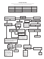
The Basic Burner Operating Scheme
1. Heat doesn’t run until there is a valid heat call and all the required heating operating conditions
Page 3
Revised: 3/11/99
A
DJM3.2 MANUAL
are met. (Example: heat switch turned on.)
NOTE: During “Service Mode” operation or safety operation, this step is ignored.
2. When a heating call is received, and before the combustion air blower is allowed to start, the
combustion blower tachometer checks for a false signal. If no signal is present, the combustion
air blower starts.
3. After the combustion blower starts, the DJM waits until the blower reaches pre-purge speed.
4. When pre-purge speed is obtained, the pre-purge light comes on and the pre-purge timer starts.
During pre-purge the heat exchanger is purged of any unwanted gases that may be present.
5. After the pre-purge cycle is complete, the combustion fan speed reduces to the internally set
ignition or light off speed.
6. The set of relay contacts between DJM terminals 4 and 2 close, thus energizing the flame relay
or ignition control device. The flame relay or ignition control device lights the pilot, proves the
pilot flame and then energizes the main gas valve. At the same time, and from the same ignition
control terminal as used for the main gas valve, a "feedback signal" is also sent to the DJM3.2
on terminal 3.
NOTE: At all times the combustion blower speed is continuously monitored. If any
problem is detected, the burner is shut off and the control logic goes to step 3.
7. After the main flame has been established and the DJM3.2 has received the feedback signal,
the combustion blower speed usually slows down. After about 10 seconds, the pilot contacts
between DJM terminals P and 1 open. If the pilot valve is wired through these contacts, the pilot
is turned off.
8. Combustion blower speed and gas valve modulates to maintain the discharge temperature and
proper combustion.
9. When the heat call is satisfied, the burner cycles off. The combustion blower returns to the
intermediate light off speed.
NOTE: Opening the fan or heat switch cycles the flame off. The combustion blower runs 1 to 4
minutes to cool burner.
10. If there is a requirement for heat within 4 minutes the control logic goes to step 6.
11. If there is no heat call within 4 minutes, the combustion blower is shut off and the control logic
goes to step 1, (unless the DJM3.2 dipswitches are set at constant purge for door heater applications,
in which case the combustion fan runs continuously).
Page 4
Revised: 3/11/99
A
DJM3.2 MANUAL
VI. SYSTEM TIMINGS
Pre-purge seconds
45
Maintained purge
DAY = 4 minutes, NIGHT = 1 minute
Blower start delay
Damper open time = 30 seconds
Burner warm up time
30 seconds
Burner cool down time
1 minute
Heat exchanger cool down time
1 minute nominal
Auto Low limit Bypass (from blower start)
5 minutes
Also resets on change to day or night
5 minutes
L/L trip timer activates for 30 seconds
before lockout
(NOTE: L/L is activated by dipswitch 8.)
Flame fail
90 seconds
VII. DIPSWITCHES
The DJM3.2 has a bank of eight dipswitches. The dipswitches are numbered on the drawing at the
beginning of this manual and are used for the following purposes:
Switches
1.
2.
3.
4.
5.
6.
7.
Voltage or current reset of the discharge temperature.
Ambient reset of the discharge temperature.
Room reset of the discharge temperature.
Not used.
Manual service mode. Must be off except when servicing.
Not used.
Maintains Combustion Fan in constant purge mode if "ON". If in night mode, S/A fan is also on
constantly.
8. Activates low limit
- "OFF" no low limit operation,
- "ON" low limit is operational.
Switches 1, 2, and 3 choose which of the possible reset styles is in use on the DJM3.2. If all these
switches are "OFF", the DJM3 operates strictly as a discharge control (even if a reset device is wired to the
control). Also note if a switch is "ON" for a reset that is not wired, then the DJM3.2 assumes the full reset
downward of the device. It is essential to recognize on new installations where a BMS reset signal
(supplied by others) was proposed but is not operational yet.
NOTE: When “Service Switch” is ‘ON’, the “FS” terminal has to be made before service
mode will work. If FS is off, service mode won’t work.
VIII. POTS
The DJM3.2 has 8 adjustable pots. These pots are listed below by location (terminal number the pot is
closest to), application, and the reference page number that covers adjustment procedures. Do not
adjust any pot without fully reading the correct adjustment procedure for that pot.
Page 5
Revised: 3/11/99
A
DJM3.2 MANUAL
Main Board Pots Located on the Right Side of the DJM3.2 and 3.3
Near
Terminal
Pot Name
Function
S
D Sen Cal
Discharge Sensor Calibration
25
U
Dis SP Cal
Discharge Set-Point Calibration
25
Page #
Z
BMS Cal
BMS Calibration (volt or current input)
16
OR
Room Cal
Room Sensor Calibration
26
+
Hi Service
Manual Firing Pot for Service Mode
28
SP
Reset Ratio
Reset Ratio (for ambient or room reset)*
12
SUB-BOARD POTS LOCATED AT THE TOP OF THE CONTROL
1
Low Fire
G
Curve Match
Low Fire RPM (Combustion Analyzer Required)
31
Curve Matching RPM (Combustion Analyzer Req’d)
31
* Note re possible incorrect label diagram and page 14
IX.
STATUS LIGHTS
There are 4 LED lights. These lights have different meanings based on their rate of flashing.
• SLOW FLASH (2 second rate)
• FAST FLASH (1 second rate)
• IRREGULAR (2 short on flashes followed by a long off)
LED 1
OFF
Discharge temperature is ok, or the unit is shut off (normal operation).
SLOW FLASH
(2 sec) Discharge temperature is below 40°F but the low limit bypass timer is
still operating.
FAST FLASH
(1 sec) Unit is locked out because discharge sensor resistance is greater
than 4000-ohms or less than 880-ohms.
ON
Unit is locked out on low limit. (Also outputs 24 VAC on L/L contacts.) If there
was a pre-purge problem while the S/A fan was running, the pre-purge
problem light would flash until a low limit trip occurs, then the failure status
would switch to low limit. Therefore, a low limit problem may have actually
been caused by a pre-purge problem.
NOTE:
If the low limit has been disabled (dipswitch 8 off) then the status light indication will not
operate.
LED 2
OFF
The heat exchanger ignition pre-purge is completed or the combustion
blower is not running.
SLOW FLASH
Trouble is with the combustion air blower tachometer or the DJM3.2 is
receiving a tachometer signal that is not consistent with the combustion
blower status. If there is a call for heat and the combustion blower IS NOT
RUNNING the DJM3.2 has likely detected a false or grounded tachometer
signal. Remove all three wires to terminals O, YS, and G. If the combustion
blower fails to start, check the combustion motor and or motor wiring. If the
motor starts, replace the speed sensor and/or magnet.
Page 6
Revised: 3/11/99
A
DJM3.2 MANUAL
If the combustion blower IS RUNNING and the tachometer signal is absent,
weak, or grounded. With a digital AC voltmeter, measure the AC volts
present on terminals “YS to G”. When the combustion blower is running
there should be 4 to 6 VAC present. If the AC voltage IS NOT PRESENT,
check the tachometer sensor to magnet gap. It should be 1/16 to 1/8 inch. If
the gap is OK, replace the speed sensor.
NOTE: No part of the speed sensor’s sensing element should be located over the end of
blower motor shaft.
If AC voltage is present, note the DJM3.2 is sensitive to the shape of the
waveform produced by the speed sensor. A sensor with leakage to ground
will provide a distorted waveform, which will cause the DJM3.2 to reject the
signal. Also a bad magnet or speed sensor will produce an uneven
waveform. Try flipping the magnet over, then flipping the speed sensor over,
before replacing the speed sensor to correct this problem.
If the supply fan were running when a speed sensor problem occurred which
activated the speed sensor light, the heat would go off. If the discharge
temperature then falls below 40ºF the L/L failure light would come on, the
supply fan turn off, and the speed sensor failure status light will be lost.
ON
The pre-purge timer is active.
LED 3
OFF
There is no heat call and/or the fan switch is open.
SLOW FLASH
There is a heat call and the fan switch and/or night contact is made, but the
heat switch is open. If the discharge temperature is below 40ºF, the S/A fan
can't run.
IRREGULAR FLASH Dipswitch 5 is in the service position and the fan switch “FS” is on.
ON
Valid heat call present, the system should operate normally.
LED 4
OFF
The flame relay or ignition control device is not energized.
FAST FLASH
Flame failure. The DJM3.2 energized the flame relay, after 90 seconds there
wasn’t a 24 V feedback voltage (to terminal 3) proving pilot flame was
established and the main valve energized. If the flame failure occurred
before the S/A fan started, then this failure light would hold its status. If the
S/A fan is on and the discharge temperature falls below 40ºF, the "L/L" light
will come on, the L/L alarm contacts close, and F/F light goes off.
NOTE: On some units, if the externally wired HIGH LIMIT control is wired to interrupt the
power to the Flame Ignition device without interrupting the power to terminal HS,
the fast flash code may indicate that the high limit contacts opened.
The DJM3.2 flame failure code/function is disabled if the service switch is on.
ON
X.
The flame relay or ignition control device is energized. The ignition control
device now has the responsibility to light the pilot flame, prove the pilot
flame, and then energize the main valve.
AUTO BYPASS LOW LIMIT
NOTE: Low limit can be disabled (dipswitch 8). Refer to Section XXIII re service
information.
The low limit set point is fixed at 40ºF. There are two low limit bypass timers, start-up and anti-noise.
The 5 minute start-up auto bypass low limit timer is started every time the night terminal energized
Page 7
Revised: 3/11/99
A
DJM3.2 MANUAL
status changes (on/off or off/on transition) or when the "SA" (supply air blower) contactor is energized or
FS status is changed to on/off.
A 30-second anti-noise low limit bypass timer is started every time a low limit condition is detected and
the 5-minute auto bypass timer has timed out. This timer is designed to prevent nuisance low limit lock
outs caused by any electrical noise which may be picked up by the discharge sensor. If the low limit
condition exists for more than 30 seconds, a low limit lockout will occur. When the low limit trips, the
DJM3.2 closes it's L/L 24 VAC output alarm contact. Also, LED 1 will be turned on steady. Flame
failure can also activate this output.
Whenever the discharge temperature is below 40°F but one of the bypass timers is operating, LED 1
will flash every 2 seconds. Also note that the low limit bypass timer is reactivated when terminal "K" is
cycled.
NOTE: For additional information see "Discharge Sensor Self Test" (Page 24).
Resetting Low Limit
To reset the low limit, turn the power off and on to the DJM3.2 control terminals "T1" and/or "T2"; or
interrupt power to terminals "FS, HS, and K" all at the same time. Most units can have the low limit
reset at the remote panel by turning the control switch off (often labelled fan or unit switch) and then on
as it will remove power to the "FS, HS, and K" terminals.
XI.
DAY AND NIGHT OPERATING STRATEGIES
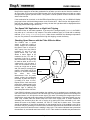
The DJM3.2 supports a variety of fan, damper, and temperature control operating schemes. The exact
operation depends upon the status of terminals “FS, HS”, and “K”.
Blower/Damper Operation
The combination of energized night (K) and fan (FS) terminals set the blower and damper operation at
night.
DAY (FS on, HS on)
Continuous Blower, Dampers Open, Discharge Control
NIGHT (FS off, K on, HS on)
Intermittent Blower, Dampers Off, Room Control
ALTERNATE NIGHT OPERATION
(HS, FS, K terminals all energized)
Continuous Blower, Dampers Off, Discharge Control
with Room Reset
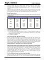
Day and Night Operating Strategies
XXX = Switch (SW.) can be "ON" or "OFF"
Heat
SW.
Fan
SW.
Night
Term.
Blower
Operation
Damper
Operation
Control Source
Control
Mode
XXX
Off
Off
Off
Off
N/A
Off
XXX
On
Off
Constant
Powered
Discharge
Day
Off
XXX
On
Off
Off
N/A
Off
On
Off
On
Intermittent
Off
Room
Night
On
On
On
Constant
Off
Discharge/Room
Night
Day Mode General Heat/Blower Operation
OFF
The first option in the above chart is "Off".
Day
The second option applies to day operation.
If the discharge sensor is warm, the supply air fan will start in 30 seconds.
Page 8
Revised: 3/11/99
A
DJM3.2 MANUAL
If the heat switch is on and there is an immediate heat call or a heat call within the first
minute of the blower starting, the blower will shut off or remain off until the burner has
been running for 30 seconds.
If during this time the heat call is lost, the blower will cycle back on but the pre-purge
will continue (Under some conditions, the supply fan may cycle a few times before the heat
starts).
If there is a heat call and the heat switch is off, and the discharge temperature is not
below 40ºF, the DJM3 will ignore the requirements for having the burner on before the
supply blower is started.
If the discharge temperature is below 40ºF and the heat switch is off, the DJM3.2 will
not start the blower until the discharge sensor rises above 40ºF and the low limit is set
in the activated position (dipswitch 8 "on"). Note that this assumes the low limit bypass
is still timing. If the low limit bypass has timed out the DJM3.2 will lock off on low limit.
Night Mode General Heat/Blower Operation
For night operation, the last three options on the above chart could apply depending on unit wiring and
DJM3.2 configuration.
•
Control Source from Room (see above chart).
•
The DJM3 must have a room thermostat connected to it.
•
If it is a modulating room thermostat it will be wired to the DJM3 terminals “V, X, Y”, and “Z”. If the
night time room temperature drops 1.5ºF below the night room set-point, the heat will be brought
on and kept on until the room temperature rises 1.5º over the room set-point. During this time, the
burner will fire at maximum rate until the room temperature is satisfied or the discharge
temperature is becoming too hot. The internal modulating high limit will act to prevent the
discharge temperature from exceeding 120ºF.
•
If using a make/break room thermostat (usually “X” and “Z”), when it calls, the DJM goes to prepurge, starts heat, fan starts, if heat at discharge air sensor exceeds 120ºF it turns off heat. If heat
is removed from sensor fast enough, the burner restarts and cycling at about 120ºF discharge
continues. If heat is not removed quickly from sensor (such as low air flow) then the S/A fan shuts
down one minute after the heat cycles off.
•
In nighttime operation the supply air fan will start about 30 seconds after the heat starts. The
supply air fan will stop about 60 seconds after the heat goes off. After the heat call is finished, the
combustion fan will run for about one minute in the cool down mode (to cool the heat exchanger).
Depending on the position of dipswitch 3, and the required control source (see above chart), the room
thermostat can be made to operate in the following manner:
•
With dipswitch 3 "on" the DJM3 operates as discharge control WITH room reset during the
day when the blower is operating continuously. At night when operating from the room thermostat,
the blower is operating intermittently. (Dipswitch 3 on.)
•
With dipswitch 3 "off" and the control in "day" operation (no power on terminal “K”), the DJM3
operates only on Discharge Control. There is no room reset being allowed from the room
thermostat. (The supply fan operates continuously during the day.)
•
At night the room thermostat operates as a room control if the heat ("HS") and night ("K") terminals
are activated on the DJM3. The supply fan will be operating intermittently and will be turned on by
the DJM3 after the room thermostat calls for heat. During intermittent blower operation, the supply
fan blower will start 30 seconds after the burner fires up and shut off 60 seconds after the burner
stops firing. The combustion blower will run for 60 seconds after the flame is turned off to assist in
cooling down the heat exchanger.
•
Lower Set-point at Night - If room reset is required during the day at one set-point, and at night
room control is to be at a lower set-point, a separate night thermostat and/or set-point dial must be
switched by an external relay.
Page 9
Revised: 3/11/99
A
NOTE:
DJM3.2 MANUAL
There is an optional room thermostat operation using a standard make/break
thermostat for room sensing in place of the modulating control. For information
on this option refer to this guide under "Make/Break Thermostat operation".
XII. BASIC BURNER OPERATION
The following controls the DJM3 burner:
•
•
•
If the DJM3 is not satisfied, it calls for heat.
Contacts 4-2 close to energize the flame supervision control.
The flame supervision control starts the pilot. If it is a good pilot it opens the main gas valve and
sends a feedback signal to the DJM3 terminal 3.
•
The DJM3 can now shut off the pilot as it controls the burner modulation and combustion fan
speed.
XIII. TEMPERATURE CONTROL – GENERAL OVERVIEW
The DJM3 is primarily a “discharge air control” but has the optional capability of electronically changing
the “calculated set-point” if external reset devices are wired correctly and the appropriate dipswitches
are configured correctly. The “calculated or operating discharge air set-point” is the mathematical
addition of the master set-point and one optional reset signal. The reset signal may be from room
temperature, ambient temperature, voltage, or current input. The voltage and current inputs will only
reset the discharge air calculated set-point (SPC) in the up direction. The room and ambient
temperature resets will reset SPC in both directions.
The only exception to “discharge air control” is when the DJM3 is wired to provide space temperature
control at night (OPTIONAL). During this night time operation the discharge sensor acts as a
modulating high limit and prevents discharge air temperature from exceeding 120ºF.
The DJM3 has proportional and integral (PI) control. On initial start-up, it is designed to bring the
discharge temperature quickly to within 10ºF of the calculated set-point. After this initial start-up time,
small output corrections to the gas valve are gradually made until the discharge air temperature is
within ±1.5ºF of the “calculated” set-point. When the heat load is light and the burner is cycling
between low fire and off there will be some temperature swing. This is especially true for the standard
(round) burner, as it is limited to a 2.5:1 turndown ratio. (This means that a heat exchanger designed for
100ºF-temperature rise will have a temperature rise of 40ºF at low fire, thus it must cycle the burner often.) Low
load operation is inevitable and the burner on/off control algorithms have been improved to provide 20
to 40% better temperature control than was possible with the original DJM.
XIV. MASTER SET-POINT
As a SET-POINT, the DJM3.2 is designed to use either:
•
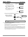
The set-point mounted on the face of the DJM3 (range of 10-35ºC or 52-95ºF). If the DJM3 face
mounted set-point is used, terminals “SP and S” must be jumped; or
•
The Johnson TE 6100-960 set-point (range of 50-85ºF and usually remote mounted). If the TE 6100960 is used as a set-point, “S to SP” is not jumpered and the TE 6100 must be wired:
TE 6100 Wires
DJM3.2 Terminals
Violet (not used, sensor)
Blue
M
Orange
S
Grey
U
Red (not used)
Q
(No jumper S-SP)
P
Page 10
TE 6000 Sensor
Revised: 3/11/99
A
DJM3.2 MANUAL
The Optional Reset Inputs
These may be controlled from room temperature, ambient temperature, voltage, or current input. The
voltage and current inputs will only reset the discharge air calculated set-point (SPC) in the up direction.
The room and ambient temperature resets will reset SPC in both directions. To use any resets, the
DJM3.2 must be properly wired and configured. The resets permit electronically changing the
“calculated set-point” if external reset devices are wired correctly and the appropriate dipswitches are
configured correctly. The “calculated or operating discharge air set-point” is the mathematical addition
of the master set-point and one optional reset signal.
Night Heat
In addition the control can be activated for night heat if configured and wired correctly. (See below for
details.) Night heat operates best on units with return air. Night heat is not as compatible with units
designed to operate as 100% “make-up air” because at night the unit will have to open the outside air
dampers and heat outside air, which is not truly cost effective. If there is a modulating or single stage
room thermostat connected to terminals “X, V, Y, and Z” the night heat function will be activated when
terminal “K” is powered.
The only exception to “discharge air control” is when the DJM3.2 is wired to provide space temperature
control at night (OPTIONAL). During this night time operation the discharge sensor acts as a
modulating high limit and prevents discharge air temperature from exceeding 120ºF.
The DJM3.2 has proportional and integral (PI) control. On initial start-up, (each time the DJM3.2 is
powered or switched to “day” mode) it will quickly raise the discharge temperature within 12ºF of the
calculated discharge air set-point. When this point is attained, small output corrections to the gas valve
are gradually made until the discharge air temperature is within ±2ºF of the “calculated” set-point.
There should be very little temperature swing once the burner has settled into its modulating range.
When the heat load is very light (often less then 5%) and the temperature rise at low fire exceeds
“calculated set-point” it becomes necessary to cycle the burner on and off to avoid overheating. When
the burner is cycling between low fire and off there will be some temperature swing.
XV. INDUCED VOLTAGE ON REMOTE CONTROL WIRING
Following are a number of discharge temperature reset methods. When any of these are ordered at
the time the unit is manufactured the control is calibrated at the factory and this calibration will satisfy
most applications, unless resistance from long wiring runs or induced voltage on the remote wiring
cause it to be out of calibration. (To check for induced voltages, disconnect all of the field wiring in question
from the DJM3.2 while the unit is left operating, and check for AC volts across each questionable wire and
ground.)
XVI. NIGHT HEAT THERMOSTATS
Modulating Room Thermostat For Night Heat
•
If used for night heat, the DJM3.2 must have a room thermostat connected to it. There are two
options, modulating or single stage.
•
If it is a modulating room thermostat it will be wired to the DJM3.2 terminals “V, X, Y”, and “Z”. If
the night time room temperature drops 1.5ºF below the night room set-point, the heat will be
brought on, and kept on, until the room temperature rises 1.5ºF over the room set-point. During
this time, the burner will fire at maximum rate until the room temperature is satisfied or the
discharge temperature is becoming too hot. The internal modulating high limit will act to prevent
the discharge temperature from exceeding 120ºF.
•
In night time operation the supply air fan will start about 30 seconds after the heat starts. The
supply air fan will stop about 60 seconds after the heat goes off. After the heat call is finished, the
combustion fan will run for about one minute in the cool down mode (to cool the heat exchanger).
•
If there is a make/break room thermostat operation, detail is noted below this next section.
Depending on the position of dipswitch 3 (room reset), and the power to FS, HS, etc. (see chart on Page
8), the room thermostat can be made to operate in the following manner:
Page 11
Revised: 3/11/99
A
DJM3.2 MANUAL
•
With dipswitch 3 "on" the DJM3.2 operates as discharge control WITH room reset during the
day when the blower is operating continuously. At night when operating from the room
thermostat, the blower is operating intermittently. (Dipswitch 3 on.)
•
With dipswitch 3 "off " and the control in "day" operation (no power on terminal “K”), the DJM3.2
operates only on Discharge control. There is no room reset being allowed from the room
thermostat. (The supply fan operates continuously during the day.)
•
At night the room thermostat operates as a room control if the heat (“HS”) and night (“K”)
terminals are activated on the DJM3.2. The supply fan will be operating intermittently and will be
turned on by the DJM3.2 after the room thermostat calls for heat. During intermittent blower
operation, the supply fan blower will start 30 seconds after the burner fires up and shut off 60
seconds after the burner stops firing. The combustion blower will run for 60 seconds after the
flame is turned off to assist in cooling down the heat exchanger.
•
Lower Set-Point at Night - If room reset is required during the day at one set-point, then at night
room is to be controlled at a lower set-point, a separate night thermostat and/or set-point dial
must be switched by an external relay.
NOTE: There is an optional room thermostat operation using a standard make/break
thermostat for room sensing in place of the modulating control. For information
on this option refer to this guide under “Make/Break Thermostat Operation”
below. It will control as per detail there.
Make/Break Night Heat Thermostats
Note the information below in the section on ROOM RESET.
XVII. ROOM RESET THERMOSTAT OPTIONS
Refer to the following sections for a full understanding of the room thermostat in your systems
application:
•
DAY/NIGHT OPERATION (option) (also refer to night information above).
•
TEMPERATURE CONTROL (information above and below).
•
MODULATING ROOM RESET (option using TE 6100 thermostat below).
•
MAKE/BREAK THERMOSTATS (option using a standard room thermostat below).
•
Additional technical information is also located under "Staged Resets and Overrides".
Note that when any override is calling, it will affect the "Calculated Set-Point" and its relation with the
"Temperature Readout". It is recommended that the service technician be very familiar with
these two sections of the manual.
Modulating Room Reset (continuous blower operation only)
Dipswitch 3 must be "on". This option also requires a TE 6100 wired:
TE 6100
DJM3.2
GREY
wired to terminal V
VIOLET
wired to terminal X
ORANGE
wired to terminal Y
BLUE
wired to terminal Z
If dipswitch 3 is on and the TE 6100 is not wired to the correct DJM3 terminals, the DJM3 will reset
the discharge temperature down as it thinks that the room sensor is very warm.
The room temperature requirements can increase or decrease (reset) the calculated discharge air setpoint. The required amount of discharge air reset can be estimated by referring to the chart on Page
13.
Page 12
Revised: 3/11/99
A
NOTE:
DJM3.2 MANUAL
If room reset calling, the “calculated” discharge temperature set-point will vary
from the setting of “master” set-point.
•
•
The room-reset feature is activated by dipswitch 3.
Room sensor calibration pot is Pot Room Cal.
•
•
Reset ratio pot is Pot Reset Ratio (refer to table below for values).
Room reset band is ±3ºF (fixed).
The “room reset band” means a room temperature error of just 3ºF will result in a maximum reset of
the discharge air set point. The actual amount reset (in degrees) varies as per both the setting of Pot
Reset Ratio and the discharge set point. The calculated discharge air set point (dial setting + reset) is
limited between 48 and 120ºF.
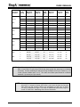
To determine the amount of reset available use the following table.
EXAMPLE: DJM3.2 set-point 70ºF; pot #5 set at 3; room thermostat set 75ºF.
•
If room thermostat sensor is at 75ºF - no reset, discharge at 70ºF.
•
If room sensor is 3° cold (72ºF), discharge is reset up full amount of its authority (+20) to 90ºF. If
room thermostat was at 73ºF then β of the reset would be used (β * 20 adds about 14º), added on
to the set-point of 70ºF giving discharge of 84ºF.
•
If room sensor is 3º hot (78ºF) full reset down will lower the discharge 13º (70 - 13 or a 57ºF
discharge).
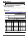
ROOM RESET AUTHORITY TABLE
(also used to determine settings when Make/Break Thermostat is calling or not calling)
Page 13
Revised: 3/11/99
A
Discharge
Set-Point
15.5ºC
60ºF
21ºC
70ºF
27ºC
80ºF
32ºC
90ºF
DJM3.2 MANUAL
Pot #5
Setting
Maximum
Temp. ºC
Minimum
Temp. ºC
Reset
Band
Width
ºC
Maximum
Temp. ºF
Minimum
Temp. ºF
Reset
Band
Width
ºF
1
25 (+9.5)
12 (-3.5)
13
77 (+17)
54 (-6)
23
2
26 (+10.5)
11.5 (-4)
14.5
79 (+19)
53 (-7)
26
3
28 (+12.5)
10.5 (-5)
17.5
82 (+22)
51 (-9)
31
4
33 (+17.5)
9 (-6.5)
24
91 (+31)
48 (-12)
43
5
38 (+22.5)
9 (-6.5)
29
100 (+40)
48 (-12)
52
1
29 (+8)
16 (-5)
13
84 (+14)
61 (-9)
23
2
30 (+9)
15 (-6)
15
86 (+16)
59 (-11)
27
3
32 (+11)
14 (-7)
18
90 (+20)
57 (-13)
33
4
37 (+16)
11 (-10)
26
99 (+29)
52 (-18)
47
5
40.5 (+19)
9 (-12)
31.5
105 (+35)
48 (-22)
57
1
33 (+6)
21 (-6)
12
91 (+11)
70 (-10)
21
2
34 (+7)
19 (-8)
15
93 (+13)
66 (-14)
27
3
35.5 (+8)
18 (-9)
17.5
96 (+16)
64 (-16)
32
4
39 (+12)
15 (-12)
24
103 (+23)
59 (-21)
44
5
44 (+17)
11 (-16)
33
111 (+31)
52 (-28)
59
1
38 (+6)
25 (-7)
13
100 (+10)
77 (-13)
23
2
38 (+6)
23 (-9)
15
101 (+11)
74 (-16)
27
3
40 (+8)
22 (-10)
18
104 (+14)
72 (-18)
32
4
44 (+12)
18 (-14)
26
111 (+21)
64 (-26)
47
5
47 (+15)
13 (-19)
34
116 (+26)
56 (-34)
60
NOTE: Room Reset Authority Pot Mislabelling
DJM 3.2 and DJM 3.3 built before Feb./99 that have square blue pots may be numbered
incorrectly. Correct numbering for this pot moving clockwise is from (5) 6 o’clock to (1) 12
o’clock (incorrect labels read 1 to 5). The older round black pots should be numbered
clockwise 1 (6 o’clock) to 5 (12 o’clock).
NOTE: The above table is not linear and reset up and down is equal at a set-point of
about 82ºF. If set-point is below 82ºF there is more reset up from the set-point
than down from the set-point. Refer to the explanation on “OR” and “V” and/or
"X" and "Z" terminals on Page 17 for reset on make/break thermostats, Page 12
for the TE 6100 Penn “Modulating Room Reset” thermostat.
Page 14
Revised: 3/11/99
A
DJM3.2 MANUAL
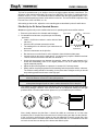
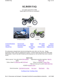
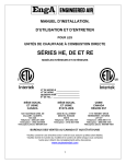
Multiple Room Sensors
Four sensors can be wired to give an average reading of room temperatures to the TRAC control.
They must be wired in a series/parallel arrangement. The drawing above drawing shows a circuit
making use of the built in sensor in the TE6100 Johnson Sensor/Setpoint assembly and using TE6000
sensors for the other three. (The other three could also be TE6100, just using the sensor wires .)
X
TE6000
Grey
TE6000
V
Orange
Y
TE6000
Z
Blue
Built in TE6100
Sensor Element
Violet
BMS Reset (continuous blower only)
Dipswitch one must be on to activate this option. This option requires an analogue voltage or current
signal to be wired to the optically isolated + and Β terminals. The analogue input signal proportionally
increases the calculated discharge air set-point. The calculated discharge set-point equals the dial
discharge set-point plus the input signal multiplied by a reset ratio factor.
NOTE: The direction of reset is UP ONLY. Refer to Page 16 for more information on
BMS reset.
The maximum amount of reset is adjustable from 15 to 60ºF. The very maximum discharge
temperature (dial set-point plus reset) is limited to 120ºF. See BMS CALIBRATION below.
The BMS reset option is activated by dipswitch 1. Reset ratio pot is Pot Reset Ratio.
NOTE:
As a standard, the DJM3 is designed to operate with 4-20 ma or 2-10 VDC into a
500-ohm load.
Some BMS devices do not have enough drive (va) to provide a full 10 VDC when connected to a 500ohm load. The input resistance for this operation can be increased to 1500 ohms by cutting resistor R43. (To
cut this resistor you must turn the board over. It is located on the back of the larger board, just below the dipswitch
block and beside Pot Reset Ratio. This is a 1-watt, 680-ohm resistor colours blue, grey, brown, gold.)
BMS reset is not truly linear. Reset will usually begin at about 4 volts. Following, is an example of
reset from one application that gives a 13ºC reset.
Page 15
Revised: 06/18/033/11/99
A
DJM3.2 MANUAL
BMS RESET FROM VOLTAGE APPLIED TO + AND Β
Current Reset Voltage
(MA) (VDC)
0
3
3
5
4
12
6
7
16
8
9
20
10
Calculated Set-Point
ºC
ºF
13
55
13.5
56
14.5
58
16
61
18
65
20
68
23
75
26
79
BMS Calibration
Apply 100% ma or voltage signal to the DJM3.2 “+” and “Β” terminals (i.e. 10 VDC or 20 ma).
Record the settings of dipswitches 1, 2, and 3. Turn off dipswitches 1, 2, and 3.
Measure the DJM3.2 calculated set-point. (DC voltage across resistor R124.)
Turn dipswitch 1 on.
Measure the DJM3.2 calculated set-point DC voltage again and adjust Pot BMS Cal (located next
to terminal Z) until the voltage is equal to the number of ºC maximum reset.
6. Return the dipswitches to their normal position.
1.
2.
3.
4.
5.
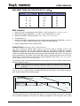
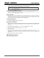
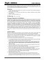
Ambient Reset (continuous blower operation only)
This option requires an ambient sensor (Johnson TE 6000-960) wired to terminals X and Z. The
discharge air set-point will be reset upwards based on the ambient temperature. Ambient
temperatures below 70ºF will gradually increase the calculated discharge air set-point. The maximum
increase in the discharge temperature will be reached when the ambient falls to 20ºF. The amount of
reset is dependant on the position of Pot Reset Ratio and the discharge set-point as set on the dial.
(The discharge set-point will be reset below master set-point if ambient is above 70ºF. In most cases when the
outside ambient is above 70ºF, the heat will be off.)
It is possible to obtain an extended temperature range by placing a 120-ohm resistor in series with the
ambient temperature sensor.
NOTE: With this resistor the discharge temperature will be at its maximum when ambient
is at -15ºF.
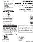
Be aware with this resistor, the calculated discharge air set-point equals the dial set-point at 35ºF
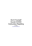
(different from above). Above 40ºF the calculated discharge air temperature will be below the dial setpoint. Note the sample on the following graph.
**
Modified Reset
Slope with 120 ohm Resistor
***
Standard Reset Slope
Vertical Axis is Dial Set-Point Line
(Adjustable 0-35°C)
20°F
-20°F
0°F
Horizontal Axis is Ambient Temperature Scale
40°F
60°F
###
80°F
##
The above graph shows the “Standard Reset Slope” if an outdoor ambient reset sensor is activated.
As the outdoor temperatures cool down, the discharge temperature is driven higher until at about
Page 16
Revised: 3/11/99
A
DJM3.2 MANUAL
25ºF the reset is at maximum. The high point of the slope is represented by (***), while (###)
represents the low end.
The second slope, the modified one, shows the results if a 120-ohm resistor is placed in series with
the ambient sensor. When this is done the outside ambient must be colder before the reset begins to
reset the discharge temperature higher. (**) Represents the high end of the slope while (##)
represents the low end.
As the slope rises above the dial set-point line, the discharge temperature increases until it reaches
the non-adjustable reset value allowed. Two factors determine how much reset is given, the set-point
of the control and how far above the set-point the slope is due to the temperature at the ambient
sensor. The resistor being added does not change the slope, only where it crosses the set-point line.
Following, is some numerical data showing how much reset is available without and with the 120-ohm
resistor added.
Pot Reset Ratio
Setting
Reset Amount ºF
(no resistor)
Reset Amount ºF (with a 120 ohm resistor in series)
1
2
10
11
18
20
3
13
24
4
16
30
5
21
37
Make/Break Resets and Overrides
1. "OR" and "V" Override
DAY OPERATION ONLY (dipswitch 3 should be off).
NOTE:
This will not operate with intermittent night blower, terminal “K” energized.
OR
Thermostat
or Contact
•
With the contact closed, discharge temperature is at 120ºF.
•
With thermostat open, discharge temperature is as per the set-point
dial plus any other reset options values that are activated.
V
The simpler version of the make/break override options is the one that closes a contact between
the DJM3.2 terminals "OR" and "V". This is designed to operate as an override for day operation
and will drive the discharge temperature up to 120º when the contacts for the thermostat are
closed. When the thermostat is not calling, the discharge temperature value is that shown on the
temperature set-point dial (either the DJM3 mounted dial or the optional remote dial).
This set up is designed for a daytime override where you have the fan operating continuously. It
does not respond to terminal “K” for night heat operation. If you attempt to operate this as a night
time override, the heat cannot start because the supply fan is not operating. Additional steps must
be taken for night operation.
If you want to take additional steps to operate the control as a night heat package, note the
following. The "OR" and "V" operation looks for the fan to be running before it can start the heat. It
has no internal method of starting the fan. If it is the intent to use this option as a night heat
function, you must have the room thermostat operate a relay that will close DJM3 contacts "OR"
and "V"; as well as have a second set of contacts that will re-establish power to the "FS" terminal.
When the "FS" terminal is powered, the DJM3 will see that the fan is operating and it will bring on
the heat to operate at 120ºF-discharge temperature until the room thermostat is satisfied.
Page 17
Revised: 3/11/99
A
NOTE
DJM3.2 MANUAL
If this system is to be used as a night heat package with the room temperature
being set back to a lower value then that used in the daytime, this system would
require a separate night thermostat and a device switching between the day and
night thermostats.
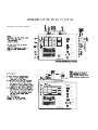
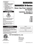
Sample wiring for “OR/V” follows:
HOT
NEUTRAL
E
C
DM
DM
DM
SA
C1
FAN
FS
Μ
LL
Air Flow
Switch
N
AS
2
HS
1
Q
3
IGN.
CONTROL
Μ
TE 6000
U
M
OR
Thermostat
S
PV
PV
SP
V
X
T1
24 V SUPPLY POWER
Y
T2
Z
CB
+
COMBUSTION MOTOR
CB
-
2. X" and "Z" Override (Day and Night Operation)
NOTE:
The unit will not discharge at the Master set-point setting. During day operation
the discharge temperature will be either:
•
Dial setting plus max upward reset, or
•
Dial setting minus max downward reset.
The amount of that reset is determined by Pot Reset Ratio. The effect of the reset is not linear
and to determine the values of the reset authority refer to the table in section on Modulating
Room Reset (Page 13). Note that the table shows a minimum temperature and a maximum
Page 18
Revised: 3/11/99
A
DJM3.2 MANUAL
temperature for each of the main values for the discharge set-point and Pot Reset Ratio settings.
When using this reset system the discharge temperature will modulate to maintain the minimum
or maximum, and will not operate at the discharge set-point.
DIPSWITCH 3 MUST BE ON TO ACTIVATE THIS FEATURE.
CONNECT “S” TO “SP” IF REQUIRED (to activate set-point on DJM3.2).
DAY OPERATION
S
•
If thermostat made between X and Z, discharge temperature equals dial setpoint plus the maximum reset upwards.
SP
•
If thermostat open between X and Z, discharge temperature equals dial setpoint less the maximum reset downwards.
Y
NIGHT OPERATION
X
•
If thermostat made then discharge temperature equals 120 F.
•
If thermostat open then the heat is off.
Z
NOTE:
When the room thermostat calls while operating in night mode, a modulating high limit
feature built into the DJM3.2 will not allow the discharge temperature to exceed 120ºF
if the unit’s heating capacity will allow temperatures to rise that high.
During the night cycle (when the DJM3's terminal “K” is powered) the readouts for the calculated
set-point (across resistor R124) will not be correct. The reading will be that of the set-point dial.
This override is difficult to understand but is more functional then the “OR to V” overrides
discussed above. The control is in effect a two level control with both levels modulating to
maintain each of their desired room discharge temperatures. If the room thermostat is not calling
then the DJM3.2 control will maintain a constant discharge temperature by modulating the burner
at a lower discharge “calculated” set-point. If the room thermostat is calling then the discharge
temperature will be set to maintain a higher “calculated” set-point, again by modulating the burner
to maintain the higher discharge temperature.
This operation is difficult to understand because the discharge temperature - as selected on the
DJM3.2 set-point dial - will never be the selected discharge temperature. Instead of using the
modulating room reset thermostat to obtain a linear room reset operation, this system takes
advantage of the “modulating” reset function at its two extremes, maximum reset up and
maximum reset down. If you refer to the chart located in the “Modulating Room Reset” section on
page 12 of this guide, you will notice that the amount of reset will be split equally at only one
point, that being at about 82ºF. It is therefore important to refer to this chart if you want to know
what the theoretical operating points will be, or else you can use the "Calculated Set-Point
Readout" to read the actual operating points with the room thermostat calling or not calling.
To understand the theoretical set up it is best to use the following example:
The desire is to serve a restaurant dining area by maintaining a space temperature of about 72ºF,
using a room on/off thermostat set at 72ºF. For this explanation we will assume there is a quantity
of fresh air for ventilation purposes that operates at 10% minimum fresh air or at a 58ºF mix box
temperature. In order to satisfy the cooling conditions of the restaurant in its busy hours, the
desire is to discharge air at about 56ºF into the space. When the restaurant is not crowded, the
space may cool down depending on solar load, etc. When the room thermostat calls for heat, the
space temperature has fallen below the desired 72ºF set-point of the room thermostat. It is now
necessary to discharge at a higher temperature then 72ºF to satisfy the rooms needs. We desire to
discharge at about 85ºF to bring the room back up to 72ºF. The difference between the two
Page 19
Revised: 3/11/99
A
DJM3.2 MANUAL
selected discharge temperatures we chose above is 85 - 56 = 29º band width. Referring to the
chart found in the "Set-Points" section and looking at the "Discharge Set-Point" of 60°F, note that
the minimum is 54ºF and the maximum is 77ºF. The band width is 23º.
Our calculations above noted we need a bandwidth of 29º. Therefore peruse down the band width
column until you find a width close to 29º with a minimum discharge close to 56ºF and a
maximum discharge close to 85ºF. This would be found under the 70ºF discharge set-point area
with Pot Reset Ratio set at 3. The minimum discharge shown is 57ºF and the maximum is 90ºF.
As we have the mix box temperature set at 58ºF, we will want the minimum temperature to be just
below that setting. Otherwise as the dampers modulate open to give cooling to the space, the heat
will be on, thus warming up the discharge air. To get the 56º-discharge set-point we desired, note
our theoretical selection gives us 57ºF with the set-point dial at 70ºF. If we turn the set-point dial
down 1º to 69ºF we will then have the desired 56º low discharge and when the room thermostat
calls the discharge temperature will rise to 89ºF. If you have a meter handy it will be best to set
these points by reading the values on the "Calculated Set-Point Readout" resistor with the room
thermostat calling and not calling. Adjustments can be made using the set-point knob and pot #5
to obtain your desired low and high discharge temperatures. (With the above set up, after the
dampers close back to minimum position, and as the outside temperature continues to fall thus
forcing the mix box temperature below the desired 58ºF, the heat will come on to maintain the
discharge temperature at 56º. This will temper the discharge air into the space thus not allowing
air that is too cold to blow onto the patrons.)
NOTE: With the above theoretical settings, the set-point will read 69º but the control
will never try to operate with a 69º discharge. It will operate with a 56º
discharge when the room thermostat is not calling and with an 89º discharge
when the room thermostat calls.
During the "Night" mode when the room thermostat calls, the discharge temperature will go to
120º if the unit heating capacity will allow it. There is a high limit function built into the DJM3 to
stop the night heat from going above the 120º discharge.
HOT
NEUTRAL
DM
C
FAN SW
λ λ
DM
Damper
Motor
SA
C1
FS
LL
H/L
4
2
IGN.
CONTROL
PV
MV
1
λ
λ
HS
3
Q
O
{
YS
{
G
{
U
M
OR
SPEED
SENSOR
S
PV
PV
SP
Room Thermostat
V
X
Y
T1
Z
T2
+
CB
-
CB
24 V SUPPLY POWER
120 V HOT
COMBUSTION MOTOR
Page 20
Revised: 3/11/99
A
DJM3.2 MANUAL
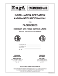
3. Linear Ambient Reset (during day and night) – Room Control with Intermittent
Blower (also refer to Page 16)
During day operation the discharge temperature will be linearly reset based on the ambient
temperature. Dipswitch 2 MUST BE ON.
DURING THE DAY
•
Linear ambient reset
•
No room reset
S
SP
Y
Connect S to SP if
required to use setpoint dial
TCR 1
X
TCR 2
DURING THE NIGHT
•
TE 6000 – 960 Sensor
120°F discharge
Thermostat or Contact
Z
TCR = Time Clock Relay
Or
•
OFF when time clock contacts are open.
•
Time Clock Contact - makes during day.
•
TCR Relay Coil - powered by time clock.
Time Clock Contact
TCR COIL
4. Linear Ambient Reset with Room Reset (during day and night) – Room Control
with Intermittent Blower (also refer to Page 16)
Dipswitch 2 MUST BE ON.
TC
Time clock is made during day
TCR
RELAY COILS
HR
Thermostat Contact
DURING DAY
•
•
S
SP
Y
Connect S to SP if
required to use setpoint dial
Thermostat open, linear ambient reset
Thermostat made, then discharge = 120ºF
TCR 1
X
TCR 2
DURING NIGHT
•
•
TE 6000 – 960 Sensor
Thermostat open, unit off
Thermostat made, discharge = 120ºF
1 HR 1
Z
V
1 HR 2
OR
5. Three Level Discharge
Dipswitch 3 MUST BE ON.
The three levels are:
•
•
•
DIAL Set-Point Β MAX RESET
DIAL Set-Point + MAX RESET
120ºF
Page 21
Revised: 3/11/99
A
DJM3.2 MANUAL
DAY OPERATION
•
•
level(s) 1 and 2 thermostats open
Disc. Set-point = dial - max. down reset
S
SP
Y
Connect S to SP if
required to use setpoint dial
LEVEL 1 THERMOSTAT CLOSED
•
Discharge set-point = dial + max. up
reset
X
Level 1
Thermostat
Z
LEVEL 2 THERMOSTAT CLOSED
•
discharge temperature = 120ºF
V
Level 2
Thermostat
OR
6. Room Override with Variable Override Set-Point (day operation only)
DURING DAY OPERATION
•
1000 to 5000 Ohm
Potentiometer
when the contact closes, the
set-point will be as set on the pot
Thermostat or
Relay Contacts
NOTE:
Set-point MUST BE HIGHER than the normal operating setting or normal reset
amount.
XVIII. CALCULATED SET-POINT READOUT (Base Plus Calculated)
Refer to Section XX for calibration.
The calculated set-point is the actual operating discharge air set-point after all the resets have been
added to the dial set-point. (Also note effect if you have ambient reset with the resistor as noted on Page 16.)
Set-Point Calculation (SPC) = Discharge Dial Set-Point + Resets
The SPC can be read using a DC voltmeter connected across resistor #R124 [¼ watt, 1210 ohms
colour code = brown, red, brown, brown (brown or red)]. This resistor is located next to the R29
temperature readout resistor but is slightly further from terminals M and Q (Β) than R29. The
calculated set-point resistor readout scale is 1 volt = 10ºC. This scale is fairly accurate from 15 to
25ºC. As temperatures approach 45ºC, the scale reads 2 to 4ºC low. DJM3.2s built after the fall of
1995 have terminals added to aid in taking this reading.
Page 22
Revised: 3/11/99
A
DJM3.2 MANUAL
SET-POINT READOUT AND DISCHARGE TEMPERATURE FROM VOLTAGE
ON READOUT PINS (diagram follows)
Voltage (VDC)
ºC
ºF
1
10
50
1.5
15
59
2
20
68
2.5
25
77
3
30
86
3.5
35
95
4
40
104
R29 is the discharge temperature reading
R124 +
R29 +
R124 is the calculated set-point reading
With the voltmeter set on the 20 VDC
scale measure the DC voltage across
R29 (the negative meter probe goes to the
resistor lead closest to terminal Q). The
readings are based on 10ºC per volt. A
reading of 0 volts = 0ºC. A reading of
2.15 volts = 21.5ºC.
Terminals
M
Calc SP
Dis Temp
Q
S
Negitive -
NOTE: When in “service mode” the calculated set-point resistor reading is disabled. During
night cycle when the DJM3.2 terminal “K” is powered the reading taken at R124 is
not a calculated set-point reading. It is only a reading of the set-point knob. At night
the DJM3.2 will try to discharge at about 120ºF if the units design temperature rise
will allow a temperature rise that high.
XIX. DISCHARGE TEMPERATURE READOUT
Refer to the above diagram for location. Refer to Section XX for calibration.
For calibration purposes, the discharge temperature at the temperature sensor, can be obtained by
measuring the voltage across resistor R29. The ¼ watt, 1820-ohm resistor (colour code brown, gray,
red, brown, (brown or red)) is located next to terminals M and Q (Β). The readings are based on 10ºC
per volt. A reading of 0 volts = 0ºC. A reading of 2.15 volts = 21.5ºC. On DJM3's built after the fall of
1995 there are test terminals added to aid in obtaining this reading.
Page 23
Revised: 3/11/99
A
DJM3.2 MANUAL
NOTE: The readable range is 0 to 55ºC. At higher temperatures the reading accuracy is
reduced. Typically at 50ºC the reading will indicate 2-3ºC lower than actual.
XX. DISCHARGE/ROOM SENSOR READOUTS, CALIBRATION, ETC.
TE 6000 Discharge Sensor Self-Test
If the discharge sensor resistance is greater than 4000-ohms or less than 880-ohms, the unit will lock
out either on low limit or bad temperature sensor. The DJM3.2 uses the discharge sensor for both
temperature control and low limit. Because of this, the DJM3.2 will not operate with a bad discharge
sensor. If the DJM3.2 locks out due to an open discharge sensor LED 1 will flash rapidly (one-second
flash).
TE 6100 Resistances
Sensor (purple and blue wires) – same resistance as TE 6000-960. Refer to the following chart.
TE6100-960 Sensor/Set Point
(purple and blue)
SENSOR
POT
Same resistance as TE 6000-960
Set-Point Dialled To
60 degrees
90 degrees
(orange and grey)
2.725 K Ω
3.272 K Ω
(orange and blue)
3.184 K Ω
2.702 K Ω
4.19 K Ω
3.71 K Ω
(blue and grey) 970 Ω
(purple and orange)
OTHER
About 1.981 K Ω (varies with element temp.)
(purple and grey)
Sensor Resistance Chart for TE 6100-960 and TE 6000-960
°C
°F
Resistance Σ
°C
18.3
Resistance Σ
°C
°F
Resistance Σ
65
983
48.9
120
1234
54.4
130
1269
60
140
1333
°F
-40
-40
602-605
-34.4
-30
633
20
68
996
-28.9
-20
665
20.6
69
1000.7
-23.3
-10
698
21.1
70
1005
65.5
150
1365
-17.8
0
732
23.9
75
1026.5
71.1
160
1437
-12.2
10
768
26.7
80
1048
76.7
170
1491
-8.7
20
804
29.4
85
1070
82.2
180
1546
-1.1
30
842
32.2
90
1092
87.7
190
1602
4.4
40
881
35.6
95
1116
93.3
200
1659
10
50
921
37.8
100
1139
98.8
210
1718
12.8
55
941.5
43.3
110
1186
100
212
1778
Reference resistance is 1035 ohms at 77°F. Resistance tolerances are ±0.05 to 0.15% at 77°F.
Temperature range +32 to +104°F. (TE 6100-960 pot is 53C3, 500R, 7/8 by ¼ shaft.)
NOTE: Engineered Air’s normal design discharge temperature range is 30 to 140ºF.
Page 24
Revised: 3/11/99
A
DJM3.2 MANUAL
Discharge Sensor Calibration
The discharge sensor this control is based on is the Johnson Control TE 6000-960, or equivalent.
(Refer to diagram on Page 23.) Above is a chart to determine if the sensor itself is accurate.
NOTE:
These controls are calibrated at the factory and in most instances field calibration
is not necessary. The discharge sensor is used for both temperature control and
low limit safety control. For that reason it is VERY important for this
calibration step is PROPERLY done. The DJM3.2 has two calibration pots. Pot
D Sen Cal is used to calibrate the discharge sensor, and Pot Dis SP Cal is used
to calibrate the discharge set-point.
1. Accurately measure the discharge air temperature at the temperature sensor.
NOTE: The sensor should be located in a stable, non-changing temperature location
between 5 and 30ºC.
2. Read the DJM3.2 discharge temperature by reading the voltage across resistor R29 (see diagram
Page 23). The ¼ watt, 1820 ohm resistor (colour code = brown, gray, red, brown, (brown or red)) is
located next to terminals M and Q. DJM3.2 controls built after the fall 1995 have terminals to aid
in this reading.
With the voltmeter set on the 20 VDC scale measure the DC voltage across R29 (the negative meter
probe goes to the resistor lead closest to terminal Q). The readings are based on 10ºC per volt.
A reading of 0 volts = 0ºC. A reading of 2.15 volts = 21.5ºC.
TEMPERATURE READOUT FROM VOLTAGE ON READOUT PINS (See diagram
Page 23)
Voltage (VDC)
ºC
ºF
1
10
50
1.5
15
59
2
20
68
2.5
25
77
3
30
86
3.5
35
95
4
40
104
NOTE: The readable range is 0 to 55ºC. At higher temperatures the reading accuracy is
reduced. Typically at 50ºC the reading will indicate 2-3ºC lower than actual.
If the discharge sensor needs calibration, adjust Pot D Sen Cal (located next to terminal S) until the
actual temperature reading on R29 agrees with the temperature reading taken at the sensor.
Discharge Set-Point Calibration
1. Record the settings of dipswitches 1, 2, and 3.
2. Turn off dipswitches 1, 2, and 3. If the “OR” terminal is used, the wire to terminal “OR” must be
removed.
3. Set the discharge set point to 21ºC. To calibrate the set point, the calculated operating set-point
(SPC) must be known. Turning the dipswitches off eliminated all the resets and the remaining SPC
value is the dial set point. (SPC = Dial set-point + reset.) The SPC can be read using a DC voltmeter
connected across resistor #R124, ¼ watt, 1210 ohms (colour code = brown, red, brown, brown
(brown/red)). This resistor is located next to the R29 temperature readout resistor but is slightly
further from terminals M and Q than R29 (drawing Page 23). The negative meter probe goes to the
resistor lead closest to terminal Q. The Calculated set-point resistor readout uses the same 1 volt
Page 25
Revised: 3/11/99
A
DJM3.2 MANUAL
= 10ºC scale as the temperature readout. This scale is fairly accurate from 15 to 25ºC. As
temperatures approach 45ºC, the scale reads 2 to 4ºC below actual.
NOTE: There are different calibration procedures for Johnson TE 6100 and the DJM3.2
face mounted set-point.
Johnson Set Point While Set at 21°C
1. Measure the DJM3 set-point across Resistor R124 and adjust Pot Dis SP Cal (located next to
terminal U) until the voltage reading is 2.1 volts.
Built In Set-Point
2. While set at 21ºC, measure the DJM3.2 set-point across Resistor R124. Loosen the set-screw on
the set-point knob and move the knob to the setting that agrees with the measured value. Tighten
the set-screw and return the dipswitches to their normal position.
For either of the above:
3. Return the dipswitches to their normal position.
Room Sensor Calibration
1. Measure the room or return air temperature and set the room set-point dial to the measured value.
(Some units have room mounted sensor/set-point dials, some have separate room set-point dial with sensor
on return air.)
2. Record the settings of dipswitches 1, 2, and 3. Turn off dipswitches 1, 2, and 3.
3. Measure the DJM3.2 calculated set-point. (See Section XVIII.)
4. Turn dipswitch 3 on.
5. Measure the DJM3.2 calculated set-point DC voltage again. Adjust Pot Room Cal (located next to
terminal OR) until the voltage is the same as was measured in step C. If the room is satisfied, there
is no reset.
6. Return the dipswitches to their normal position.
BMS Calibration and Set Up
Refer to notes for BMS on Page 14.
Page 26
Revised: 3/11/99
A
DJM3.2 MANUAL
XXI. DJM3.2 SET UP SHEET
MAY 7, 1998
AUTO BYPASS LOW LIMIT dipswitch 8
ON____ENABLED
OFF____DISABLED
APPLICATION
____DOOR HEATER constant maintain purge dipswitch 7 ON
____OTHER (maintain purge time 4 minutes dipswitch 7 OFF)
ROOM RESET
____Dipswitch 3 ON
RESET RATIO POT RESET RATIO ____ 1=23°F, 2=27, 3=32, 4=44, 5=60 (approx. values)
NOTE: The reset is bi-directional. The numbers given are for total degree of reset.
AMBIENT RESET
_____ Dipswitch 2 ON
RESET RATIO POT RESET RATIO _____
STANDARD WIRING
1=10°F, 2=11, 3=13, 4=16, 5=21
With 120 ohm series resistor – 1=18, 2=20, 3=24, 4=30, 5=37
NOTE: The reset is bi-directional with series resistor and effectively unidirectional for
standard wiring. The numbers given are for total degrees of reset. The ambient
temperature range through which the discharge temperature is reset is:
Standard connection = 20 to 70°F (up reset only)
–
Series resistor = -10 to 72°F. The temperature where no reset occurs is at an
ambient of about 40°F.
VOLTAGE OR CURRENT RESET _____ dipswitch 1 ON
RESET AMOUNT IN ºC
specify amount ______ (8 to 32)
NOTE: Voltage and current reset is in the up direction only.
Page 27
Revised: 3/11/99
A
DJM3.2 MANUAL
Blower/Damper Operation
The combination of energized night (K) and fan (FS) terminals set the blower and damper operation at
night.
DAY (FS on)
Continuous Blower, Dampers Open, Discharge Control
NIGHT (FS off, K on)
Intermittent Blower, Dampers Off, Room Control
ALTERNATE NIGHT OPERATION
(HS, FS, K terminals all energized)
Continuous Blower, Dampers Off, Discharge Control
with Room Reset
XXII. BURNER SET UP
Manual Service Switch
The service switch allows complete manual control over the burner-firing rate. When the service
switch is in the on position, and if the fan switch is on, the burner will cycle on. The burner will be held
on and will not cycle off. Rotating Pot Hi Service will adjust the firing rate from minimum to maximum.
The calculated set-point resistor readout does not function in this mode.
NOTE: If the service switch is on, the DJM3.2 will not lock out on flame failure. This was
done to prevent the whole unit from locking out on flame failure resulting in faster
burner servicing. The low limit is still active in the service mode.
Manual Firing Set Up Pot
This pot is designed to allow a service technician to manually set the burner to any firing rate he
chooses. If the service switch (dipswitch 5) is on and the blower switch (terminal FS) is powered, the
burner firing rate is controlled by the service pot (Pot Hi Service). Pot Hi Service is located close to the
+ terminal and the dipswitches. Rotating this pot will allow the firing rate to be set at any rate between
low and high fire.
NOTE: S/A fan (terminal FS) may need to be turned on manually when service switch is
on.
Important Usage Notes Regarding the Service Pot
•
•
•
•
•
The unit must not be left in the service mode. When leaving the unit make sure that dipswitch
5 is OFF.
When the service switch is on the burner will not cycle off. (The S/A fan may need to be turned on
manually when service switch is on.)
Low fire is at approximately pot position 6 o’clock and high fire is at pot position 3 o’clock.
The low limit is still functional and may lock out if the firing rate has been manually set too low.
An irregular flashing of LED 3 indicates that the unit is in service mode. (Dipswitch 5 is still ON.)
Burner Selection
The DJM3.2 is designed to operate with both the standard (round burner plate) and high turndown
(rectangular) burners. The selection is made by cutting a jumper wire # R100 which is located on the
small board. (The DJM3.2 must be turned over to access the jumper wire.)
NOTE: Jumper wire R100 is cut only for the high turndown burner operation. Caution –
do not cut resistor R100 on the large board.
The small board contains two pots located next to the terminal strip. These pots are accessed from
the front of the control and are designed to be adjusted by a qualified service technician only.
DO NOT ADJUST ANY OTHER POTS LOCATED ON THE SMALL BOARD, WHICH ARE NOT
ACCESSIBLE FROM THE FRONT OF THE DJM3.2.
Page 28
Revised: 3/11/99
A
Pot 1 (located next to terminal G)
is the curve matching pot. It is
possible to use the DJM3.2 with
several different Maxitrol valves.
Each of these valves has a
slightly different opening curve.
The curve matching pot allows
the DJM3.2 to be adjusted to
control all of these valves.
DJM3.2 MANUAL
Top Board
Bottom
Board
Pot Low Fire (located next to
terminal 1) is the low fire RPM
adjustment pot. This pot is used
to adjust the low fire RPM (low
fire air). The low fire speed is
adjustable from 1150 to 1400
RPM (high turndown) and 1800 to
2000 (standard burner).
Jumper R100
To be cut for
high turndown
burner
2 amp fuse
NOTE: The light off RPM is fixed and is non-adjustable. Adjusting the low fire speed will
have no effect on the light off speed.
Combustion Set Up
Preview of Combustion Set Up
There are two burners available.
The high turndown (rectangular) burner
•
•
•
•
•
•
Is capable of 15 to 1 turndown.
You must cut the R100 jumper on the back of the DJM3.2.
Pilot ignition at about 2300 RPM.
10:1 Modulation 1250 and 3400 RPM (20.8-56.6 Hz).
15:1 Modulation 1195 and 3400 RPM (19.91-56.6 Hz).
Note carefully which “M” series valve is in use.
The Standard (or Round) Burner
•
•
•
•
Limited to about 2.5 to 1 turndown.
No jumper to be cut on DJM3.2.
Pilot ignition at about 2700 RPM.
Modulation between 1850 and 3400 RPM.
For Either Burner
•
•
•
•
•
When measuring combustion, ensure probe of analyser inseerts fully into the flue connection to
the heat exchanger. Measuring at the flue outlet may be a diluted reading due to air mixing into
the flue.
First set up high fire
Then set up low fire
Adjust midrange firing (curve matching pot)
Adjust pilot
Page 29
Revised: 3/11/99
A
DJM3.2 MANUAL
NOTE: If combustion is not set correctly it can result improper burning which may
produce products of combustion that smell, carbon and or an excessive amount
of water in the flue. Care should be taken to set burners up properly. Note that
temperature of the air and fuel may have a great affect on the set up you select.
If both the combustion air and the fuel are at a constant temperature throughout
the heating season, once combustion is set it should remain similar through the
season. However, this usually only occurs on indoor units. Setting up an outdoor
unit is not the same as setting up a unit or a boiler inside a building.
When a unit is located outside, it is subject to different temperatures of combustion air and fuel
through the season. These temperatures affect the densities, thus affecting the resulting combustion
process. In some instances units that operate with 3% oxygen at Β40º ambient temperatures will be
found to operate at 9% oxygen on an 80ºF day. How the gas line is run (indoors or across the roof) is
the largest contributor to this problem.
It is better to have a burner that runs clean and doesn’t produce a lot of water from the flue
throughout the season then to set up for best efficiency. Also, we recommend that the probe for
combustion analysis be placed directly into the heat exchanger outlet rather then in the flue. This is
because air can enter into the bottom of the flue and dilute readings in the flue.
Refer also to “Water and Condensation from Combustion” on Page 42 regarding another problem
with improper combustion set up.
High Turndown (Rectangular) Burner
High Fire Set Up
1. Turn on the service switch (dipswitch 5).
2. Set manual firing Pot Hi Service (located next to the + terminal) to high fire. Adjust the high fire
input to the correct clocked rate. Adjust combustion air slider or inlet damper until the high fire
O2 reading is between 3.5 and 4.2%.
Low Fire Set Up
•
For both 10:1 and 15:1 turndown burners.
NOTE: Most high turndown DJ units will employ on of the following Maxitrol modulating
DC volt gas valves.
Series 20
420, M520, M620. These valves do not have high fire regulators. High fire pressure is
set up at the appliance regulator.
Series 50
550, M650, ES350. These valves do not have high fire regulators. High fire pressure is
set up at the appliance regulator
ES345D-L
This valve has a built in high fire regulator. Often used on DJ140 models.
The above valves differ from each other in size, configuration, BTU capacity, physical layout, and low
fire set up.
Check the unit you are working on to verify what type of modulating gas valve you have to ensure the
correct combustion set up method is used.
Top Loading
Ensure that there is a 3" aluminium tubing connected from the top of the modulating gas valve vent
connection to the burner box. This is to guarantee that the varying burner box pressure allows the
proper flow rate through the modulating gas valve. Also ensure that the small vent hole under the oval
shaped cover is sealed off with silicone or Tremco tape. When doing combustion analysis it is
important that the top of the valve be sealed by either reinstalling the cap after each adjustment, or
placing your finger fully over the top to seal the open top on the valve. The reason for this requirement
is that the valve is “top loaded” which means that the valve is having pressure from the combustion
fan added to the top of the valve’s diaphragm thus increasing the gas flow through the valve,
Page 30
Revised: 3/11/99
A
DJM3.2 MANUAL
especially at higher flow.
Series 20/M420, M520 and M620 (high turndown)
As these valves have 2 low fire adjustments the following procedure should be followed carefully.
Once the high fire pressure and combustion has been set up at point “B” above, turn the manual
firing pot (fully CCW) to achieve low fire. Adjust the low fire RPM Pot Low Fire until the low fire
speed on the combustion fan motor is 1250 RPM ±10 RPM (20.8 Hz) for 10:1 set up. (1195 RPM
±5 (19.91 Hz) for 15:1 turndown.) At this point the DC voltage reading at the modulating gas valve
terminals should be 0 VDC.
Under the cover on the Maxitrol series 20 valve is an adjustment screw (brass or silver) that has a
lock ring which uses a special tool (two very small screws) to loosen it, holding it in place.
1. There is a lock ring that needs to be loosened first. Turn it fully CCW, now turn the slot screw
in the centre of the lock ring (spring activated low fire adjustment) full CCW.
Caution: Do not over torque this screw at the top or bottom of its adjustment or it will
break the “c-clip” inside the valve, thus allowing the spring to ride free.
2. Adjust the low fire bypass screw at the bottom side of the valve body until the O2 reading is
between 16.0% to 16.5%. (16.5 to 17.5% oxygen for 15:1 turndown.) At these settings the
turndown will be very close to 10:1. The maximum CO at low fire is 80 PPM.
3. Adjust the Service Pot (manual firing Pot) up very slowly until the DC volts at the modulating
gas valve terminals are about 2.25 VDC. If the voltage rises over 2.25 VDC while adjusting
the manual pot, turn it down and start again from less than 1.5 VDC until 2.25 VDC is
reached.
4. Check the O2 reading again at this point. If the O2 has increased, adjust the spring activated
low fire adjustment on top of the valve until the O2 reading is same as the low fire reading at 0
VDC. You are correcting for valve hysteresis with this adjustment.
5. CURVE MATCHING PROCEDURE
Switch to high fire setting (approximately 3450 RPM or 57.5 Hz) for 1 minute. Adjust the Service
Pot (manual firing Pot) down very slowly until the combustion motor speed is about 3060
RPM (51 Hz). Let the burner stabilize for 2 minutes, then re-check O2 reading. If O2 has
dropped to less then the original high fire O2 reading, adjust the curve matching pot (pot 1 near
terminal G on the top of the DJM3.2). Adjusting CCW increases the O2 reading by reducing the
voltage to the Maxitrol modulating gas valve. The curve matching pot only changes the
voltage to the gas valve, it does not affect fan speed.
6. If the curve matching pot is adjusted to the fully CCW position and the O2 reading is still not
within 10% of the original high fire O2 reading, add a 180-ohm 2 watt resistor across the
modulating gas valve terminals; repeat above test until proper curve matching is achieved. (A
150-ohm, 2-watt resistor may have to be used if O2 level still does not rise to within 10% of original
high fire O2 reading.)
Switch burner to low fire again and re-check low fire, both at 0 VDC and 2.25 VDC. (An
addition of a resistor above may have changed the low fire setting, if it was needed.)
7. Lock the locking ring on the spring activated low fire adjustment screw. Failure to lock it may
cause the screw to vibrate loose allowing low fire gas pressure to increase. This can create
sooting of burner parts and the heat exchanger. If the locking ring is missing, drop one drop of
Loctite thread locker 222 onto the brass screw threads.
Series 50/M550, M650 AND ES350 (high turndown)
These valves have only 1 low fire adjustment (spring activated low fire).
8. The combustion set up is similar to the above except there is no low fire bypass adjustment
on the bottom of these valves. Therefore simply set up low fire by turning the manual firing
Pot Reset Ratio to the low fire position - 1250 RPM ±10 RPM 20.8 Hz. (15:1 turndown set at
Page 31
Revised: 3/11/99
A
DJM3.2 MANUAL
1195 RPM, 19.91 Hz.) Voltage to the series 50 valve should be 0 volts DC. Adjust the spring
activated low fire adjustment at the top of the modulating gas valve (small screw) until an O2
reading of 16.8% to 17.5% is achieved.
9.
Lock the low fire adjustment screw as described in point 7 above and then adjust the curve
matching pot as in points 5 and 6 above.
Type ES345D-L (high turndown)
As this valve has 2 low fire adjustments the following procedure should be applied.
10. Bring the unit to low fire using the service firing pot fully CCW. Adjust Pot Low Fire until the
combustion fan is turning 1250 RPM ±10 RPM (20.8 Hz). (15:1 turndown is 1195 RPM, 19.91
Hz.) Voltage to the ES valve should be 0 volts DC. The low fire bypass adjustment on this
valve is under the top cover on the large port and the adjustment inside it is marked:
Increase ÍÎDecrease
After removing the cover, loosen the locking screw first before making adjustment. This
should be done at 0 VDC to the modulating gas valve terminals and the spring activated
low fire brass screw turned fully CCW and the locking ring loosened off.
11. Bring voltage to gas valve at 2.25 VDC and adjust the spring activated low fire adjustment
located in the head with the electric modulator (smaller screw under cap) to achieve the same
O2 reading as the one achieved at 0 VDC (16.8% to 17.5% O2). After this is complete then
adjust the curve matching pot 1 as described in points 5 and 6 above.
Pilot Set Up (high turndown)
1. On high turndown units, ensure air tube to pilot is free of debris and blockages and then set pilot
pressure to 3.5" WC.
2. Pilot set up is not as critical on the high turndown burner as there is not as much heat on it as on
the regular burner.
Standard (Round) Burner
Most standard turndown DJ units will employ one of the following Maxitrol modulating DC volt gas
valves.
Series 20 Β M520, M620
These valves do not have high fire regulators. High fire
pressure is set up at the appliance regulator. If used on the
standard burner, the low fire adjustment located on the bottom
side of the valve is to be adjusted fully clockwise (no bypass).
Series 50 Β M550, M650, ES350.
These valves do not have high fire regulators. High fire
pressure is set up at the appliance regulator. This series of
valve has been replaced with the M520/620 series.
ES345D-L
This valve has a built in high fire regulator.
High Fire Set Up
1. Turn on the service switch (dipswitch 5).
2. Set manual firing Pot Hi Service (located next to the + terminal) to high fire. Adjust the high fire
input to the correct clocked rate. Adjust the combustion air slider or inlet damper until the high
fire O2 reading is between 3.5 and 4.2%.
Low Fire Set Up
Standard Burner Low Fire Set Up 2.5:1 turndown
Low fire blower input is 40% of high fire blower input.
Page 32
Revised: 3/11/99
A
DJM3.2 MANUAL
The low fire procedure set up is similar to that for the high turndown burners noted above. The
difference is the maximum allowable CO at low fire is 200 PPM. The low fire O2 reading should be
between 10.9% to 11.3%. The combustion slider is different than the high turndown slider. It is a
plate that slides between the blower outlet and the burner box. The low fire RPM is adjusted using
Pot Low Fire to 1850 ±10 RPM (30.5 Hz).
After setting up the low fire, adjust the curve matching pot as described in points 5 and 6 above.
Pilot Set Up for DJ Series Standard Burners
Do not set up pilot until you are confident the burner is operating with correct air/fuel mixture.
1. Ensure the pilot tube is free of debris and blockages.
2. On standard round burners, set pilot as per the following
procedure.
•
•
•
•
•
•
•
•
•
Ign Control
MV meter
Install a 10,000-ohm resistor in series with the flame
rod circuit.
Connect a DC voltmeter across the resistor.
The reading will be in millivolts if your meter does not
10,000 ohms
auto scale.
Connect a manometer to the pilot line.
Run the burner on main flame for a few minutes to have the burner plate warm.
Leave the pilot on but turn the main gas off. You will have to jumper the DJM3.2 terminals
1 and P to do this and remove the wire from terminal 3.
As low pilot gas pressure can damage the ceramics, reduce the pilot gas pressure to 2.5
inches and immediately return it to a higher pressure. This is to ensure the pilot gas
regular responds properly.
Adjust the pilot valve regulator to a pressure in excess of 4.5 inches pressure.
Slowly reduce the pilot gas pressure while watching both the pressure and the voltmeter.
The millivolt reading should be increasing. At the point where it begins to fall you should
stop reducing pressure and return to the high spot.
NOTE:
The fall in pressure could only be as small as a couple of millivolts. This point
should be between 4.5 and 2.5 inches pilot pressure.
NOTE:
Some smaller burners (DJ40 250,000 BTUH and smaller), may need to have a
screw placed through the pilot air tube to reduce the amount of air to the pilot.
This reading is used to determine the adjustment that will usually give the best pilot lighting
and proving strength. However, care must be taken to not adjust the reading for pilot gas
pressure below 2.5 inches water column pressure or you will break the pilot ceramics.
Too large a gap.
Raise burner plate
up to centre.
OK
Next, visually observe the pilot flame. It should be visible at a minimum of 3 of the holes
around the pilot. If the pilot cannot be seen then it is likely burning too deep into the pilot box.
If this is occurring check that the gasket on the pilot assembly is forming a tight seal. Also
ensure that the burner is located in the center of the burner tube. If it is mounted too low then
too much air can flow over the top of the burner and affect the pilot.
Page 33
Revised: 3/11/99
A
DJM3.2 MANUAL
NOTE: After set up is complete make sure to turn off dipswitch 5.
Propane Gas
Combustion set up for propane fuels for either the high turndown or the standard burner are similar to
the above. The only modification suggested is it may be desirable to increase the oxygen settings by
1 to 1.5% above those for natural gas.
Due to the quantity of fuel that can be drawn off a propane tank, it is often necessary to equip a
propane fuel system with a vaporizer. The usual sign that a vaporizer is required is that the units fuel
supply falls off as the line “freezes”. The user usually observes:
•
•
•
Lack of temperature rise,
Rumbling or shaking burner due to air/fuel mix,
After turning the unit off for awhile the fuel line thaws and restarting it, all appears to be normal.
Combustion set up for propane fuels for either the high turndown or the standard burner are similar to
the above. The only modification suggested is it may be desirable to increase the oxygen settings by
1 to 1.5% above those for natural gas.
High turndown burners operating on propane fuel will generally exhibit the following:
High Fire
At 3.5% O2 will appear yellow from behind the burner. However, if you could view it
from the other side of the burner you would see blue as the flame lengthens out.
Low Fire
At 16% O2 the flame will likely be yellow. At 17% O2 the flame will likely be blue and
yellow.
Inlet/Manifold Pressure Settings
Manifold pressure settings that the unit was tested and clocked at in the factory are recorded on the
unit rating plate. Any attempt to clock a unit in the field should be done with care as corrections for
density (altitude and station pressure), temperature, and the correction factor for the meter are often
overlooked, thus leading to an incorrect conclusion.
Inlet gas pressures are recorded on the unit label. At high fire inlet gas pressure to the unit should not
fall below 6.25" on units designed for 7" inlet pressure. If design is for 14" pressures should not fall
below 12".
If design is for 11" propane gas, then inlet pressures should not fall below 10". Note that with propane
fired units it may be necessary to equip the propane system with a properly sized vaporizer.
XXIII. SPECIAL SERVICE NOTES
On Board Fuse
The DJM3 is equipped with a 2-amp fuse. This fuse is located on the bottom of the main board. If
there is 24 VAC to terminals T1 and T2 and the DC voltage from terminals O to G is 0 VDC, check the
fuse. (10.5 to 11.0 VDC is normal.)
Resetting Low Limit, Bad Sensor, Flame Failure Lockout
This can be done by either removing power to the DJM3 or by just removing the power to terminals
“HS, FS”, and “K”. (Refer to Page 8 “Resetting Low Limit”.)
Page 34
Revised: 3/11/99
A
DJM3.2 MANUAL
Low Limit Lockouts
NOTE: If your application does not require it, L/L could be disabled. If there is an
intermittent problem with the discharge sensor, a false low limit lock out code
may be generated. This happens if the discharge sensor generated an initial
lockout and then the reason for the sensor lock out disappeared. (Refer to Section
X for more detail on the low limit.)
If the discharge sensor calibration is not correct you can also have low limit lockouts.
Also, be aware if the heat call light comes on, the burner lights, and there is not adequate heat to
allow the discharge temperature to rise above the 40ºF. Low limit setting for the period of time that
the low limit is being bypassed, and then the low limit light will come on when the unit locks off. If the
low limit sensor then warms up, both the heat call and low limit light should remain on until someone
resets it by turning the power off to the DJM3.2. We strongly recommend that no one reset the
control until the status of all of the troubleshooting lights are recorded.
Items that will turn off other alarm lights when low limit light is activated:
What happens if ignition fails on morning start-up?
On a Warm Day
•
•
•
Dampers open
Supply fan starts
If heat call light comes on:
Supply air fan is shut off (assumes first call must be delivering cold air into building).
NOTE:
•
If this occurs during the first 36 seconds of morning startup, the supply fan
would stay off.
Dampers go closed.
Combustion fan starts, purge light comes on.
Purge cycle completes, purge light goes off.
Ignition enable light comes on.
Now, if ignition failure occurs:
Ignition enable light flashes 90 sec. later.
Combustion blower turns off.
Low limit light will come on if discharge sensor falls below 5ºC (40ºF).
Sensor or ignition light that was flashing will go off when low limit light goes on.
On a Cold Day
•
If discharge sensor is in warm area:
•
Dampers will open.
Supply fan will start.
Fan and dampers may go off due to low limit if discharge sensor cools.
Ignition attempt as above.
If discharge sensor is in a cold area:
Dampers open, fan awaits response that heat is on.
Ignition attempt as above.
Supply fan may start and run on low limit bypass until flame failure light comes on.
Then dampers, supply fan and combustion fan shut off.
Only LED 4 flashes at one-sec interval – FLAME FAILURE.
In any of the above three situations, assuming that the original problem did not rectify itself you will
Page 35
Revised: 3/11/99
A
DJM3.2 MANUAL
likely find the supply fan off and the combustion fan off when you arrive at site. Note the condition of
all of the lights. If you now turn the DJM3.2 power off for 30 seconds and then turn it back on, watch
the lights as the ignition process retries. If an ignition or sensor problem exists it should be evident
within a few minutes.
If the combustion fan is seized, or the Hall Effect Speed Sensor is faulty, etc., the DJM3 will display
pre-purge lockout until the discharge sensor cools to below 40ºF. When the low limit bypass timer that has now started to time - completes its timing, the low limit light alarm will be displayed and the
pre-purge problem alarm light will turn off.
Two Speed VAV Applications or High Limit Tripping
The DJM3.2 likes to see stable operation. If the set-point is changed rapidly (lowered), the DJM3.2
may take up to 3 minutes to fully respond. The same conditions apply to a load that is suddenly
reduced. (Vanes closing or low speed operation.) Under these conditions the discharge temperature
may rise. If a problem is encountered with the high limit tripping, consult the factory.
Checking Speed Sensor with the Fluke 80 Series Meter
The DJM3.2 has a speed
sensor to allow the control to
closely monitor the combustion
fan speed. There is a fixed 10
VDC output from the DJM3.2
terminals “G” and “O” to the
speed sensor chip. The chip
allows a return signal to be
measured on the “YS” and “G”
terminals. If the fan is rotating
above 500 RPM, the signal can
be read as either an AC or DC
voltage and it will be about 5
volts. This is because the fan is
turning at a high rate of speed
and your meter is averaging the
reading. If the DJM3 has 24 volt
power to it, and the combustion
fan
motor
has
been
disconnected from its power
supply, turning the combustion
fan slowly by hand will result in
a reading of 0, then 10 VDC.
Repeat as the north and south
poles of the magnet pass by the
Hall Effect chip. If the pre-purge
problem light is flashing the
above steps should be checked.
Magnet Retainer
Ring
Magnet
Blower Shaft
Hall Effect
Sensor
1/8” Gap
If the DJM3.2 indicates a pre-purge problem the problem can be analysed more completely using
one of the Fluke 80 series meters. The DJM must see a near symmetrical square wave coming from
the speed sensor or it will reject the sensor signal. This wave is formed as the magnet spins on the
shaft with the north and south poles passing a Hall Effect speed sensor. This speed sensor is a very
small “chip” located under the shrink wrap at the end of the copper tube. A simple method for
estimating the waveform when the unit is running is by setting the Fluke multimeter to AC volts.
Attach the meter to the DJM3.2 terminals “YS” and “G”. Press the Hz button once. The number
should read between 15 and 59 Hz depending on the speed of the fan. If the reading is over 59 Hz
the sensor may be grounding out as the motor’s maximum RPM should be 3450 RPM. Press the Hz
button a second time and the meter is reading % duty cycle. This number indicates how symmetrical
the waveform is, and should read close to 50% ±2.5%. If the number is outside those parameters the
Page 36
Revised: 3/11/99
A
DJM3.2 MANUAL
“pre-purge problem” light may be flashing. Check the sensor location and magnet quality.
Occasionally poorly manufactured magnets produce an irregular magnetic field. Sometimes
reversing the magnet on the shaft will correct this problem (turning it around). Also refer to LED 2 for
more info.
If the test is done only for voltage and it proves to be correct, there could still be a problem as the
DJM3 has a refined sensing circuit. This circuit is looking for the magnet to be split fairly evenly. The
duty cycle test gives a reasonable view of the magnets split between north and south poles.
Speed Sensor Values
With the speed sensor disconnected from the DJM, the following are approximate values read with a
fluke meter at 50ºF.
Scale @ Megohms
Scale on Diode
Positive Lead
(Red)
Neutral Lead
(Black)
Value (Megohms)
Neutral Lead
(Black)
Value
Red
Yellow
Green
Infinite
25.2
Yellow
Green
Infinite
1.6
Yellow
Red
Green
Infinite
Infinite
Red
Green
Infinite
Infinite
Green
Red
Yellow
Infinite
4.6
Red
Yellow
Infinite
0.652
Pre-purge Light Coming On (when not supposed to)
There can be two reasons for this:
1. A power spike is being picked up through the “O, YS” or, “G” terminals. Make sure the DC wiring
is not run common with the AC power wiring. If separating the wires doesn’t cure the problem,
shielded wire may have to be used.
2. A problem with the DJM3.2.
Constant Purge Light, No Ignition Attempt
This can only apply to units that have a relay connected to the main gas valve connection of the
ignition control. One set of the relay contacts control power to the gas valve, the other set controls
power to the DJM3.2. If the heat call light and the pre-purge light are both staying on and there is no
attempt to slow the combustion fan down to ignition speed, check if DJM3.2 terminal 3 has constant
power on it. If the previous heat call was completed and terminal 3 did not have the signal removed
because the relay contacts are stuck closed, it can result in the lockup as described.
Failed Operation or Solid State Control Contacts by Others
There have been a number of new controls introduced into the marketplace recently that allow a
building to be controlled by a central computer (BMS or Building Management System). Many of these
devices use relays to switch external power devices on and off and their operation is fine. However,
some of the new devices use “opto-couplers” or “solid state contacts”. These devices will not
interface properly with the DJM3.2 contacts “FS, HS, K, or terminal 3”. The solid state contacts allow
enough “voltage leak” through them when they are in an off (open) position to cause the DJM3.2 to
malfunction. Voltage leaks of 4 to 5 VAC are common. Only dry contacts should be tied to the
DJM3.2 terminals unless instructed to do otherwise.
S/A Fan Off Before Room Satisfied in Night Heat Mode
Problem is on DJM3.2 only. This problem occurs when the room thermostat calls and the discharge
air sensor gets too warm too fast (above 120ºF), due to overheating warm building air in the discharge
Page 37
Revised: 3/11/99
A
DJM3.2 MANUAL
plenum and the supply fan, delayed on, cannot remove the heat fast enough after it starts. The
burner modulates off, as the discharge sensor is limited to 120ºF, 60 seconds later S/A goes off, and
then combustion fan goes off. Room thermostat is still calling.
Resolution
1. In night mode ensure that terminals “HS, K, and FS” are powered. This will make the supply fan
operate continuously at night.
2. Turn dipswitch 7 on. This will place the DJM3.2 into a constant combustion fan and constant
supply fan mode.
3. Install an automatic fan switch (AFS).
Air Balancing - Refer to next item
Discharge Temperature in Cold Weather
Installation and air balancing is often done during warmer weather than that experienced in the cold
of winter. If the air balancer did not allow for the changes that will occur in air volume in cold weather
then the unit will appear to be short of temperature rise. As the fan is a constant volume device and
as it is located before the heat exchanger, air will expand as it is heated. The amount of change will
be about 20% increase in air volume from -30ºF to +70ºF. Therefore, to give a rough sample,
assuming a 10,000-CFM unit located in an area that reached -30ºF in the winter was being air
balanced on a 75ºF day with the heat off. The unit design temperature rise is 100ºF. It should be
balanced to deliver about 8,200 CFM. On a day that is -30º, the fan is still delivering 8,200 CFM onto
the heat exchanger, but as the air expands over the exchanger there is 10,000 CFM coming off of
the unit. Temperature rise should meet the 100ºF design to give a discharge temperature of 70ºF. (If
the unit had been balanced to deliver 10,000 CFM on the 75ºF day, then on the -30ºF day noted above, the
temperature rise would only be about 80ºF to give a final discharge temperature of about 50º at about 11,800
CFM.)
Ignition Problems
Check the condition of the pilot assembly. Check for damaged or dirty ceramics, proper gasket, and
pilot set up. If you are still having problems lighting the burner, check the items itemized below.
If these are all OK, check the combustion settings. Either the manifold pressure is incorrect, orifices
plugged, the curve matching pot is set wrong, or the combustion air set incorrect. For further
information refer to the section for combustion set up.
If you have been having problems lighting the burner, check the following items:
1. If the combustion has been set up, the ignition should be checked. Whenever the total air slider
has been adjusted it affects how much air flows into the pilot air tube.
2. Occasionally some ignition control devices have the power to throw a spark through the casing
to the mounting screw near the spark connection, or through the back of the case. Mount the
ignition control off the wall on insulated spacers and do not install a mounting screw next to the
spark wire location.
3. Check the resistance of the flame and spark rod to the wire connector terminal on the rod. This
should not exceed 2-ohms. If it does, replace the assembly.
4. Ensure that the ignition control and its transformer secondary are both adequately grounded. If
there is not an adequate ground then there will be a weakened flame rod signal.
5. Some extreme cases of airborne electrical noise a special sheathing is available to shield heavy
ignition spark wire. Please consult factory. It may be necessary to install a ground wire from
burner ground terminal to chassis. Scrape the paint on chassis.
6. Spark gap should be set at 1/8 inch.
7. Check for cracked porcelains on the spark and flame rods. These have been found to be
cracked in the area where they pass through the mounting plate also. You cannot see into this
area and you can even have it feel tight. (If possible it may be best to check it with an ignition device.)
Page 38
Revised: 3/11/99
A
DJM3.2 MANUAL
8. Ensure there are no burrs or dirt in the pilot line orifice and air tube. These items have often
been found with dirt, rust, insulation, paper, etc., blocking them. This includes checking the short
connector at the blower housing where the rubber tube attaches. Also ensure no capacitor
mounting screw is blocking the inlet to the pilot tube.
9. Usually changing the pilot assembly will not have much of an affect on the pilot signal if both
assemblies are in good condition and installed correctly.
10. Ensure the pilot assembly gasket is tightly installed to stop air leakage into the pilot area.
11. Standard (round) burner only. If the burner plate is not centered in the hole, it may allow too
much of a gap over the top of the burner, thus increased airflow through the larger opening may
roll onto the pilot box. Place a spacer under the burner plate to raise it into a centered position.
12. Due to the low capacities of some small units with standard (round) burners only, there may be
too much air entering into the pilot air tube. It may be necessary to reduce this air quantity by
placing a screw through the side of the combustion blower outlet in a manner that the screw also
passes through the metal tube that the rubber hose connects to. This normally only occurs on
units with an input of less then 300,000 BTUH. Some units have a screw mounted capacitor,
ensure the screw does not obstruct the pilot tube’s air path.
13. If a BMS signal is applied, caution should be taken about removing the transformer grounds that
may interfere with the BMS signal. It is possible that you may have disconnected the ignition
control or ignition transformer ground.
14. Water and ice have been located in the pilot gas lines, in the pilot air tube, in the pilot box, and in
the pilot gas orifice. Ensure these areas are free of moisture, locate the source and correct it.
15. Snow, ice, or water on the ignition control(s) can stop a pilot from igniting or proving. These
devices and their associated parts must be kept clean and dry.
Regulator Gas Pressure Responses
On some indoor units the vent orifice fitting on the RV appliance regulator is to be vented to
atmosphere. The field installed vent line should be sized adequately, especially on longer runs. If
there is more than one regulator connected to a common run, which includes the main regulator and
the line, is not adequately sized, changes in pressure on the RV diaphrams are applied to all
regulators. This includes the main regulator so an erratic inlet pressure will result and cause
improper combustion and also burner pulsating problems.
Some DJ unit manifolds have RV appliance regulators with a vent-limiting orifice, usually a brass
orifice marked ‘12A06’. Ensure that this tiny orifice is free of dirt or debris. A plugged orifice will
impede regulators opening flow and cause improper air/fuel mixtures.
If these are all OK, check the combustion settings. Either the manifold pressure is incorrect, orifices
plugged, the curve matching pot is set wrong, or the combustion air set incorrect. For further
information refer to the section for Combustion Set Up on page 29.
Pilot Sensing Problems
Check the condition of the pilot assembly. Check for damaged or dirty ceramics, damaged gasket,
and pilot set up. Ensure the pilot tube is free of debris and blockages. Note that there is an orifice
where the pilot gas line is connected to the pilot air tube. This orifice is sized to the BTU and altitude
requirements of the burner. It must be free of dirt and burrs to operate properly. If there are problems
lighting or proving the pilot that do not appear to be related to the ignition/flame supervision device
then carefully clean and inspect this orifice from both the gas tube and air tube side. If a burr exists it
is usually best to remove it by pushing it into the air tube from the gas tube with a small pin or orifice
drill, then break it off by inserting a object into the air tube.
If these are all OK, check the combustion settings. If the firing rate is too high, the curve matching
pot 1 is set wrong, or the combustion air is too low. Note previous section pertaining to combustion
set up and pilot set up for the style of burner you have (standard round, or high turndown rectangular
burner). If all the combustion parameters are correctly set, consult the factory.
Page 39
Revised: 3/11/99
A
DJM3.2 MANUAL
DJM3.2 Locks Up on Trial for Ignition
When all regular troubleshooting items have been addressed about possible lockup problems, look
at this possible problem.
Some chips supplied to us in controls manufactured about mid 1995 that will lock up very shortly
after the spark starts. This is often an intermittent problem and usually will have the DJM3.2 lock up
without any lights on, however, some lights may be on in certain cases. The DJM3 will reset if power
is turned off for 30 seconds and then restored. If you witness this problem you will note that just after
the combustion fan goes to light off speed the lockup will occur within a fraction of a second of the
spark ignition beginning. Usually a pilot does not get time to light. The problem is radio frequency
noise created by the spark interferes with the DJM3.2 electronics.
Installation of a radio frequency filter will resolve the problem. Disconnect the wires from T1 and T2
on the DJM3. Connect them to the RFI filter. Connect the outlet of the filter to the T1 and T2
terminals with wires no longer then six inches in length if possible. Ensure the RFI filter is well
grounded.
A filter that will resolve this problem is available at most electronics wholesalers. One we have used
successfully is the CORCOM model 1VK1 EMI filter.
L-2X1.86 MH
C-2X.1UHF (x2)SH
2X.0055UF (Y)
R-1.5 megohms
Internal changes have been made to DJM3.2 controls to eliminate this RFI problem on controls
manufactured about April 1996.
Rumble During Light Off
The low fire combustion air quantity being too great usually creates this condition, or the low fire gasfiring rate is set too low. Always check the main gas inlet pressure first before making any adjustments.
At high fire it should be a minimum of 6½ inches on units designed for 7-inch natural gas inlet
pressure. (Minimum 12 inches on 14-inch natural gas design and 11½ inches on propane units.)
Rumble is usually not a problem with the rectangular shaped high turndown burner. On the standard
burner it is possible to get small amount of rumble whenever a burner is lit after being cold for an
extended period of time. After the first light it settles down. This is because the warm burner has a
greater back pressure than the cold one; thus a lower air velocity occurs when the burner plate is
warm.
One of the more common causes on the regular burners (round burners) is if the combustion blower
light off speed is set too high. Check if the light off speed is too high with an accurate tachometer or by
using a meter that measures hertz connected to the “Y and G” terminals of the speed sensor. Light off
speed is 2700 RPM (45 Hz).
Another item that can create rumble on the standard (round) burner is if the turndown is adjusted too
low. At low fire the standard (round) burner can only modulate to 40% of the high fire rate. This leaves
too much air at low fire for the quantity of fuel. To correct increase the low fire manifold pressure to the
proper firing rate. A rough rule of thumb for low fire manifold pressure is:
DJ40
DJ60
DJ100
0.6"
0.6"
0.8"
Ensure that these pressures are set with the modulating gas valve at low fire (1.8 VDC on its terminals)
and the combustion fan running at 1800-1850 RPM.
Combustion Fan Motor Surging in Speed
There are two possible causes for this. First, both the DJM3 and the combustion fan motor
transformers need to be powered from the same two phases of the three phase power supply. Second
Page 40
Revised: 3/11/99
A
DJM3.2 MANUAL
cause occurs if a combustion fan motor is surging in its speed after the motor has been in operation for
an extended period of time, it is likely that the “triac” is overloaded and is running hotter then design.
When this occurs the surging is caused by the triac shutting down due to heat. The surging occurs at
lower modulated speeds of the combustion fan and pulses about twice a minute. Be careful to not
incorrectly assume this problem, as it may also be possible the fan is changing speed in relation to the
demand from the DJM3.2 control system. The surging described above will not occur until the triac has
operated for a few minutes at low speed and built up considerable heat.
Modulating Valve Will Not Respond to Signal to Open
Items that may contribute to this are:
•
•
•
Ice in valve (in bottom or above diaphragm).
Burnt out coil.
Sticky substance or debris in valve.
Improper Burning
•
•
•
Plugged 12 AO6 vent orifice (on units equipped with one on regulator).
Modulating valve sticks.
Incorrect burner setup.
Improper Burning After Changing Combustion Motor Or Fan
If the fan is located at a different spot on the motor shaft, it changes the airflow pattern and quantity.
The quantity is changed by the size of the gap changing around the fan inlet. This allows more or
less air to “leak” from the fan discharge side back to the fan inlet.
Modulating Valve Sticks When Returning to Low Fire
If the modulating valve sticks partly open as the combustion fan slows down, the combustion process
will be very poor. The products of combustion may smell badly or in rare instances even form
carbon. The usual symptom of a sticking valve is when voltage is low to it and the manifold pressure
is higher then it should be, and a solid rap on the valve corrects the problem.
Sooting Burner/Heat Exchanger
Soot is created during improper combustion. Do not try to correct combustion set up with a badly
sooted burner or heat exchanger, clean it first. One cause of sooting is on units with horizontal flues.
The wind blows into the outlet harder then the combustion fan blows. Correct this by installing a
vertical chimney (double walled in colder climates). The second item to check on High Turndown units
is a loose lock ring on series 20 valves. Described in section XIV, subsection Low Fire Setup – refer
to the type of valve in your unit. The third item is combustion set up is correct but the modulating gas
valve sticks partially open when returning to low fire. This can usually be determined by monitoring
gas pressure and analysing combustion while at low fire, then rapping the modulating valve if above
was not correct. If the valve was stuck then it releases and low fire returns to the desired settings.
(Refer to combustion set up.)
On heat/cool units the combustion air is normally drawn by the combustion fan from the intake
screen located on the compressor floor area. As this floor area is cantilevered it can plug up with
blowing snow, especially if the unit is mounted on a low level roof curb. This can cause combustion
air to starve and result into sooting of the heat exchanger.
Smell From Flue (Products of Combustion)
Smells are usually created by improper combustion set up. This can be due to a sticking valve (note
above), low inlet gas pressure, or just a bad combustion set up. Note the comments below about
combustion set up.
Page 41
Revised: 3/11/99
A
DJM3.2 MANUAL
Water and Ice From Combustion
These heat exchangers are very efficient. Water is one of the major products of combustion and as
such must be controlled. The units are equipped with a drain. It is however best to allow water to
leave the unit in the flue gases in vapor form. Combustion that is set at maximum efficiency will
produce excess moisture. Often it is desirable to have 1% to 2% higher excess oxygen readings then
those normally listed to assist in keeping the flue gases drier. Also note that extended chimneys can
contribute to condensation problems (especially if they are not insulated or at least double walled). Water
in the heat exchanger can lead to premature failure due to thermal stress or freezing. Another
source of excess condensation is when a unit designed with capacity to heat 100% outside air is
operating with very little outside air, therefore operating at a low fire or cycling. This allows the cool
flue gases from low fire to cool and condense in the chimney.
Burner Pulsing, Backfiring, Exploding, Noisy
An improper air/fuel mixture usually causes this condition. Do not attempt to do any combustion
analysis until the inlet fuel pressure has been checked with the unit operating at high fire. (This should
include other loads on the same gas system being on.) If the inlet pressure falls too low then the velocity of
the air over the flame will be too great and tear the flame. If the burner is designed and set up for
proper fuel pressure and it does not have it, it will react exactly like a burner with too much
combustion air. If the inlet fuel pressure is correct at high fire then the combustion set up should be
checked.
If an explosion occurs after the burners flame has definitely extinguished, and the burner is in the
process of being re-lit, it is likely due to a leaking gas valve. It is recommended that both the main
and pilot valve be replaced if you cannot prove the source of a leak.
Fire Without Combustion Fan
If there is a flame operating in the burner section without the combustion fan in operation, check to
see if there is power across the DJM3.2 terminal 3 and neutral. Record the result. Next check to see
if there is power on DJM3.2 terminals 2 and neutral. Record the result. Next, check to see if there is
power to DJM3.2 terminals T1 and T2. Record the result. If there is no power to any of the above
terminals and if the unit has not had any wire changed, there should not be any power to the pilot or
main gas solenoid valve. Very gently turn off the manual valve on the pilot line. Check to see if the
fire has gone out. If it has, then the pilot solenoid is leaking and should be changed. If there was no
difference, gently turn off the firing valve for the main manifold. If this stops the fire, this would prove
the main solenoid-blocking valve was leaking.
If there is no power to any of the above terminals and if all wiring is as per the original diagram, there
should not be any power to the pilot or main gas blocking valve. Very gently turn off the manual valve
for the pilot gas. Check to see if the flame has gone out. If it has then the pilot solenoid is likely
leaking. If the flame is still on gently turn off the main firing valve. If this stops the flame then the main
valve has been leaking. At this time turn off the line valve to the unit and repair the problem.
Replacement of Combustion Fan Motors
Motors being used for combustion fan application are applied to a device (DJM2 or DJM3) that
reduces the motor speed. Speed reduction of a motor results in additional heat being generated
within the motor as well as reduced cooling capability from the motors internal cooling fan. If a motor
that is not designed for this duty is installed on the DJM, it may result in failure of the new motor
and/or the DJM. For this reason we recommend combustion fan motors only be replaced with motors
that meet all the specification requirements of the original motor. Also note improper burning above.
Set Up When Replacing DJM3.2 in Field
1. The two pots on the back of the board are factory adjusted and should not be field adjusted, they
are for the tachometer calibration. Only on the odd occasion should the low fire light off pot be
adjusted, that being if the burner rumbles on during every light off (even when warm).
2. There are two possible burners that the DJM3.2 can be applied to. Check the burner in your unit
and if necessary cut the jumper before mounting the control. (See Burner Selection, Page 28.)
Page 42
Revised: 3/11/99
A
DJM3.2 MANUAL
3. If there is a BMS system connected to the DJM3 determine if it is necessary to cut R43 before
mounting the control. The best way is to look at the board you are removing.
4. The DJM3.2 uses a Johnson TE 6000 discharge air sensor.
•
Turn service switch 5 on to adjust the burner.
•
•
•
Adjust Pot Hi Service marked “SP” to high fire and set up the burner.
Adjust low fire.
Adjust curve-matching pot.
After adjusting the flame, set the following pots:
•
•
•
Adjust Pot D Sen Cal discharge sensor calibration.
Adjust Pot Dis SP Cal discharge set-point calibration.
Turn on any dipswitch that was in use on the existing control. This would usually be to
activate a reset control.
• Note operation of any resets connected, noting reset ratio, room cal etc. as needed.
5. Set dipswitch 7 to configure "maintain purge" operation Section VII.
6. Set dipswitch 8 to configure low limit operation Section X.
Side Wall Venting
There is an air-proving switch that is wired into the speed sensor circuit on indoor units. This is to
prevent any ignition attempt unless airflow through the wall vent is proven.
Main Gas Valve Over Travel Switch (Option)
If the main gas valve does not return to a closed position on completion of a heat call, the contacts
will be open preventing the pilot from lighting.
Simulating a Heat Call
Unlike many controls, you cannot simply open circuit or short-circuit the DJM3.2 discharge air sensor
to simulate a full call for heat or no heat. The DJM3.2 checks the discharge sensor to insure it is
operating between two values. If the sensor is too low in value the DJM3.2 will trip on low limit (value
below 881 ohms). If the sensor resistance is too high, the DJM3.2 will lock out on a bad sensor. The
acceptable sensor values lie between 880 to 4000 ohms. If you wish to simulate a heat call from the
sensor instead of using the manual firing pot then you can do one of the following:
1. Substitute a 950 to 1005-ohm resistor in place of the discharge air sensor, and then adjust the
size of flame with the set-point pot.
2. Substitute a variable potentiometer with values between 850 through 1250-ohms. This will allow
a simulation of the operation of the control with discharge temperatures from about 32 through to
125ºF.
XXIV. MISCELLANEOUS NOTES
Combustion Blower Speeds
DJM3.2 configured for the REGULAR ROUND BURNER
•
•
•
LOW FIRE COMBUSTION BLOWER SPEED is about 1850 RPM ±10 RPM (30.8 Hz)
HIGH FIRE COMBUSTION BLOWER SPEED is about 3400 RPM
LIGHT OFF SPEED is about 2700 RPM
DJM3.2 configured for the HIGH TURNDOWN BURNER
Page 43
Revised: 3/11/99
A
•
•
•
DJM3.2 MANUAL
LOW FIRE COMBUSTION BLOWER SPEED
at 10:1 turndown is about 1250 RPM ±10 RPM (20.8 Hz)
at 15:1 turndown is about 1175 RPM ±10 RPM (19.91 Hz)
HIGH FIRE COMBUSTION BLOWER SPEED is about 3400 RPM
LIGHT OFF SPEED is about 2300 RPM
Maxitrol Modulating Gas Valve Voltages
The different Maxitrol valves modulate through about the following voltages:
•
•
•
•
M650 or M651
M550 or M520
M450 or M420
MR212
2
2
2
2
-
13 VDC
12 VDC
11 VDC
11 VDC
XXV. VALVE DRAWINGS
Page 44
Revised: 3/11/99
NO FAN OPERATION ON DJM-3
Dip switch #5 should be in off position.
24 VAC on T1 T2
Yes
No
Is heat call light SOLID ON upon
call for heat?
Yes
- Restore power
- Check line voltage
No
Fan should start after 30 seconds
Yes
Fan will start 30 seconds
No
but fan doesn’t start
No
Yes
Is 24 VAC on N to K terminals?
Yes
No
Normal Operation
Is 24 VAC on N to FS terminals?
Yes
If burner fires for 30 seconds
but fan doesn’t start
No
Unit is in night mode and
fan operation is
intermittent. Fans runs with
respect to room heat call
Fan should start after 30 seconds
Yes
No
- Units is in OFF position
- Restore unit to ON status
Is power 24 VAV on N to SA?
Yes
Problem is external to DJM-3. Check
fan motor contractor or motor may be
faulty. Check other interrupting contact
as per unit internal wiring diagram.
No
Replace DJM-3
NO HEAT ON DJM-3
The following is a flow chart covering many general operating/troubleshooting situations.
If a more detailed manual is needed, contact the nearest EngA factory.
LED ON
2 SEC. FLASH
1 SEC. FLASH
LL Lockout
Low Limit Bypass
Discharge Sensor Open
Prepurge
Prepurge Problem
Heat Call
HT Switch Open
Ignition Enabled
Flame Failure
Dip switch #5 should be off for this quick test.
24 VAC on T1 T2
Is heat call light SOLID ON upon
call for heat?
Yes
Yes
- Restore power
- Check line voltage
No
No
Heat call light 2 sec. flash?
Restore Power
to ‘HS’
No heat called for
Is PP light SOLID ON?
Yes
No
INT. FLASH
Service Mode
-
Did combustion
fan start?
Yes
Prepurge light flashing?
Yes
No
No
This may indicate
certain lockout
has taken place.
Refer to chart at
top of this page.
- Faulty Comb. Fan
motor, fuse, power
- No output from
DJM “CB” terminals
Yes
No
Are any lights on or flashing?
Yes
No
Check for 10 VDC power on O or G
Yes
No
Suspect faulty DJM-3.
Replace DJM-3
- Unit is in prepurge
- Comb. Blower slows to light off speed.
ignition enable light should come on
within 45 sec. (max. 60 sec.)
Yes
DJM fuse failed or
DJM is faulty
Review following steps as
there is a problem with
combustion motor or speed
sensing. See DJM-3.2
manual for more information.
No
Is Ign. Enable
light on?
Yes
Suspect faulty DJM-3.
Replace DJM-3
No
Is 5 VDC across
terminals “YS and G”
while comb. fan runs
Yes
Power goes to burner
supervision relay. It lights
and supervises pilot.
After it sends feedback
signal to DJM terminal 3,
DJM will modulate comb.
Fan and gas - normal
operation.
Unit stuck in
pre-purge
Speed
Sensor
operates
but signal not
good - turn
magnet over
or replace it.
No
Is zero or 10 volts across
terminals “YS and G” while
combustion fan runs - yes?
Replace
Speed
Sensor
ORIGINAL DJM-3.2 OR 3.3 WIRING
CB
CB
P
1
3
MV MV VS
CS
G
YS
O
M
4
+
LED ON
SA
C
LL
2
DM
1
LL LOCKOUT
2 SEC FLASH
1 SEC FLASH
LL BYPASS
D SEN OPEN
2
PRE PURGE
PP PROBLEM
3
HEAT CALL
HT SW OPEN
4
IGN ENABLE
S D
P I
C S
INT FLASH
-
Q
+
-
D SEN CAL
+
-
DIS SP CAL
S
SERVICE MODE
FLAME FAIL
BMS CAL
--
DM
U
V
+
X
Y
ROOM CAL
Z
N
+
HS
HI SERVICE
K
20
FS
15
T2
DJM CONTROLLER
T1
MODEL DJM 3.2
CB2
CB1 PV2
30
10
35
PV1 VFB VN VFB MX1 MX2 VS CS
120
24
CFR
AL
FR
DM1
GS
2
3
1
4
5
YS
2 SEC FLASH
1 SEC FLASH
D SEN OPEN
1
LL LOCKOUT
LL BYPASS
2
PRE PURGE
PP PROBLEM
3
HEAT CALL
HT SW OPEN
4
IGN ENABLE
OS
D TEMP
COM
+
-
D SEN CAL
+
-
DIS SP CAL
M
Q
S
U
V
+
FLAME FAIL
BMS CAL
--
DM2
-
* RESET RATIO
INT FLASH
SERVICE MODE
+
SP
SPC
LED ON
SA
C
1-BR 5-SS
2-AR 7-NC
3-RR
8-LL
25
OR
X
Y
ROOM CAL
N
Z
+
HS
HI SERVICE
K
LOW
20
FS
15
T2
DJM CONTROLLER
T1
MODEL DJM 3.4
25
30
10
35
8 OPEN 1
2
3
1
4
5
OR
+
1-BR 5-SS
2-AR 7-CCF
8-LL
3-RR
SP
RESET RATIO
.