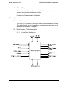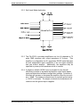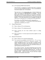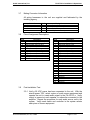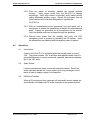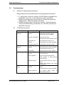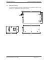
1
Installation & Operations Manual
Model #: PA-475-01-x
Stereo/Subwoofer Amplifier
Document #540144
7300 Industry Drive, North Little Rock, AR 72117
Phone: 501-955-2929 Fax: 501-955-2988
www.audiointl.com
Audio International, Inc.
PA-475-01-x Installation & Operations
Document Revision History
Rev. Level
IR
Date
1/2000
Description
Initial Release
Reference Documents
Document #
N/A
Drawing #
522195
Description
PA-475-01-x Outline Drawing
Service Bulletin List
Service
Bulletin #
Subject
Manual
Revision
Revision
Date
Table of Illustrations
Illustration #
1
2
Description
Block diagram – Typical Application
Reference Drawings
Page #
5
15
PROPRIETARY INFORMATION NOTICE: Despite any other copyright notice, this document and
information disclosed herein contains confidential, proprietary designs owned by Audio
International, Inc. Neither this document nor the data contained herein shall be reproduced, used
or disclosed to anyone without the written authorization of Audio International, Inc.
Document #540144, Rev. IR, 1/2000
Page 2 of 15
Audio International, Inc.
PA-475-01-x Installation & Operations
Table of Contents
Section
Description
1.0
1.1
1.2
1.3
1.4
General Information …………………………………………….
Introduction ………………………………………………………..
Purpose of the Equipment ……………………………………….
Operational Features……………………………………………...
Optional Equipment ………………………………………………
4
4
4
4
5
2.1
2.2
2.3
Application ………………………………………………………..
Introduction ………………………………………………………..
Block Diagram – Typical Application ……………………………
Data Bus Control…………………………………………………..
5
5
5
7
3.1
3.2
3.3
3.4
3.5
3.6
3.7
3.8
3.9
Installation ………………………………………………………..
Prior to Installation ………………………………………………..
Unpacking and Inspection ……………………………………….
Cautions & Warnings ……………………………………………..
Wiring Requirements ……………………………………………..
Physical Characteristics ………………………………………….
Electrical Characteristics …………………………………………
Mating Connector Information ……………. …………………….
Pinout Assignment Descriptions ………………………………...
Post-Installation Test ……………………………………………..
7
8
8
8
9
9
10
10
11
11
4.1
4.2
4.3
Operations
Introduction…………………………………………………………
Audio Source……………………………………………………….
PA/Chime Function………………………………………………..
12
12
12
12
5.1
5.2
Troubleshooting …………………………………………………
General Troubleshooting Procedures …………………………..
Troubleshooting Chart…………………………………………….
13
13
13
6.1
Specifications ……………………………………………………
Unit Specifications ………………………………………………..
14
14
Reference Drawings …………………………………………….
15
2.0
3.0
4.0
5.0
6.0
7.0
Page
Document #540144, Rev. IR, 1/2000
Page 3 of 15
Audio International, Inc.
PA-475-01-x Installation & Operations
MODEL # PA-475-01-x
Stereo/Subwoofer Power Amplifier
1.0
General Information
1.1
Introduction
This manual contains information for the proper application, installation,
and operation of the Audio International, Inc. (AI), Stereo/Subwoofer
Power Amplifier, Model No: PA-475-01-x. The “-x” suffix designates the
type of connector utilized. Also included are physical and electrical
characteristics of the unit.
1.2
Purpose of the Equipment
The PA-475-01-x is a 300-watt, 4 channel, Class D stereo/subwoofer
power amplifier. The unit accepts low level entertainment audio source
inputs and amplifies them to levels suitable for driving speakers. The
amplifier has inputs for the aircraft’s page/chime function along with PA
override to mute the entertainment audio when the page function is
utilized.
There are four (4) sets of speaker outputs that can be configured to drive
up to four (4) full-range speakers or two (2) high-range speakers and two
subwoofers depending on unit configuration mode. The amplifier is one of
the building blocks of a complete cabin audio system.
1.3
Operational Features
Listed below are key features of the PA-475-01-x:
q
q
q
q
q
q
q
q
q
q
q
Output power 4 x 75 watts RMS, less than 1% THD
Class D
Can be configured for up to 4 full-range speakers or 2 high-range
speakers and two subwoofers
Two (2) entertainment audio inputs in full-range mode, one (1) input in
bi-level mode
PA key overrides entertainment audio
Controlled and interfaced with AI control equipment via AI’s proprietary
RS485 serial data bus
Emergency power input
Weight-on-Wheels configurable over AI’s proprietary RS485 serial data
bus; audio level can automatically be increased or decreased while in
flight
Solid state circuitry
Compact, lightweight housing
Low heat generation
Document #540144, Rev. IR, 1/2000
Page 4 of 15
Audio International, Inc.
1.4
PA-475-01-x Installation & Operations
Optional Equipment
Audio International, Inc. offers a complete line of speaker systems to
enhance any aircraft entertainment system.
Contact your AI representative for details.
2.0
Application
2.1
Introduction
The PA-475-01-x is part of a complete cabin audio entertainment system.
The application of the unit is specific to a particular aircraft based on the
desires of the customer or designer.
2.2
Block Diagram – Typical Application
2.2.1 Bi-Level Mode Application
Document #540144, Rev. IR, 1/2000
Page 5 of 15
Audio International, Inc.
PA-475-01-x Installation & Operations
2.2.2 Split Level Mode Application
2.2.3 The PA-475-01-x provides amplification on four (4) channels at 75
watts RMS minimum with output impedance of 4-ohms. This
amplifier is configurable via AI’s proprietary RS485 serial data bus
as dual independent stereo amplifiers or as one stereo amplifier
and one bi-level amplifier. Additionally, the amplifiers may be
specified to power-up with speakers active or inactive.
2.2.4 A weight-on-wheels (WOW) input is provided for use that will
effectively increase or decrease the amplifier output levels based
upon pre-determined software configuration settings. Activation of
this input will increase or decrease the amplifier output by as much
as +/- 20dB. The weight-on-wheels input is constant ground active
(<1.2VDC to activate). The weight-on-wheels level adjustment will
continue until the ground input is applied.
Document #540144, Rev. IR, 1/2000
Page 6 of 15
Audio International, Inc.
PA-475-01-x Installation & Operations
2.2.5 Emergency power input provides for necessary power to power
amplifiers and PA/chimes controls during emergency conditions. If
both amplifiers are configured for full range operation (split-cabin),
then both amplifiers will be powered when this input is activated.
If the second internal amplifier is configured as a bi-level amplifier,
the unit will automatically deactivate the subwoofer amplifier
whenever the main power is removed and will reactivate
automatically when the main power is restored (if on prior to the
main power deactivation).
As shown in the diagram above, the two power inputs on the P13
connector are wired in a diode ‘OR’ configuration allowing for
operation from either power bus.
2.3 Data Bus Control
Multiple amplifier configurations are possible utilizing AI’s proprietary
RS485 serial data bus, allowing independent control of each unit. The
number of possible amplifiers in a system is dependent on other modules
used within the cabin audio system, maximum eight (8) amplifiers.
There are no controls on the PA-475-01-x. Operational control of the unit
is handled by commands via AI’s proprietary RS485 serial data bus.
Programmable features are set upon installation utilizing an external PC
(typically a laptop). A software program designed by AI specifically for this
task enables the following features:
•
•
•
•
•
Unit ID for control of the amplifier from various locations in the
aircraft in a multi-amp configuration
Initiation of the bi-level mode to utilize the crossover on the four
speaker outputs for subwoofer and high range usage
Settings for Weight-on-Wheels input
Audio level controls
Speaker power up – “OFF or ON”
Document #540144, Rev. IR, 1/2000
Page 7 of 15
Audio International, Inc.
3.0
PA-475-01-x Installation & Operations
Installation
3.1
Prior to Installation
Prior to installation, the following items should be considered:
3.1.1 During the design and layout of the aircraft cabin, careful
consideration of the location of this module is necessary. Some of
the items to be considered include:
• Space
• Available power supply
• Environmental conditions (temperature, humidity, etc.)
• Length of cable runs
• Location of other aircraft systems (i.e. oxygen delivery)
3.1.2 The PA-475-01-x must be installed to conform to the standards
designated by the customer, installing agency, and existing
conditions as to the unit location and type of installation.
3.1.4 Mounting screws are required to secure the unit. Refer to Section
7.0, Reference Drawings, for mounting hole diameters and
configuration.
3.2
Unpacking and Inspection
Carefully open the packaging and remove the PA-475-01-x. Verify that all
components have been included in the package per the packing list.
Inspect the unit for damage. Retain the packing materials and packing
list.
If damage has occurred during shipping, a claim must be filed with AI
within 24 hours and a “Return Request Authorization Number” must be
obtained from AI. Refer to the front cover of this manual for address and
telephone number of Audio International. Repackage the unit in its
original packaging materials and return it to AI following instructions given
by the AI representative. If no return is necessary, retain the packing
materials for storage or reshipment.
Document #540144, Rev. IR, 1/2000
Page 8 of 15
Audio International, Inc.
3.3
PA-475-01-x Installation & Operations
Cautions and Warnings
3.3.1 It is important to do a pin-to-pin power and ground check on all
connectors. Ensure that power and ground are applied only where
specified. Damage to the unit may result if power or ground is
applied to the wrong points.
3.3.2 DO NOT connect or disconnect the module while power is applied.
3.3.3 DO NOT remove any factory-installed screws. Damage to the units
may result and void any warranties.
3.3.4 Ensure the amplifier is properly grounded from the grounding lugs
on the case to the aircraft frame.
3.3.5 DO NOT connect or disconnect any speaker when power is applied
to the amplifier.
3.3.6 ESD (Electro Static Discharge ) guidelines shall be followed.
3.4
Wiring Requirements
3.4.1 Introduction
The installing agency shall supply and fabricate all external cables
and mating connectors. The length and routing of external cables
must be carefully studied and planned before attempting installation
of the equipment. Allow adequate space for installation of cable
and connectors. Avoid sharp bends and placing cables near
aircraft control cables. Maintain a minimum clearance of three (3)
inches from any control cable.
If wiring is run parallel to
combustible fluid or oxygen lines, maintain a separation of six (6)
inches between the lines.
3.4.2 Audio Lines
All audio input cables shall be 22 AWG minimum twisted shielded
pair. Audio output cables shall be 18 AWG minimum, 16 AWG
preferred. All audio input and output lines require twisted, shielded
cable with the cable shields grounded at the source.
3.4.3 Power Wires
All power and ground wires shall be 16 AWG, minimum. Power
ground wires must be grounded within twelve (12) inches of the
unit. All wires shall be in accordance with MIL-W-22759 or
equivalent. Protect power wires with circuit breakers or fuses
located close to the electrical power source bus. Ground the stud
within 12” of the unit using 10 AWG, minimum.
Document #540144, Rev. IR, 1/2000
Page 9 of 15
Audio International, Inc.
PA-475-01-x Installation & Operations
3.4.4 AI’s Proprietary RS485 Serial Data Bus
The PA-475-01-x is designed to interface with other AI equipment
via AI’s proprietary RS485 serial data bus. This is a serial data bus
that allows multiple units to be connected.
The data bus is to be implemented using a twisted shielded pair
cable in accordance with MIL-W-27500 or equivalent. The wire
size for the conductors in this cable is to be 22 AWG (minimum).
The shield is to be connected wherever a shield pin is provided.
Shield terminations are to be made as close to the connector pin as
possible. In the event shield pins are not provided, the data bus
shield must be terminated per AI’s proprietary RS485 specification.
All modules on the RS485 data bus shall be connected in a
“daisy-chain” configuration. AI’s proprietary RS485 serial data bus
specification is available upon request.
3.5
Physical Characteristics
3.5.1 Refer to Section 6.0 for unit dimensions.
3.5.2 Refer to Section 7.0 for attachment points.
3.5.3 When mounting the unit, allow sufficient space for mating
connectors.
3.5.4 Allow a minimum of 1-inch air space around the amplifier for heat
dissipation.
3.6
Electrical Characteristics
3.6.1 Refer to Section 6.0 for electrical specifications.
3.6.2 Two connectors are available on the PA-475-01-x. P1 is an 11-pin
connector designed to mate with an “Amphenol” connector. The
signals interfaced through P1 are two sets of left/right speaker
outputs, +28 VDC main input, and +28 VDC emergency input. The
emergency input is required for cabin page and chime functions in
case of primary systems power failure.
P2 is a 25-pin connector. The signals interfaced through P2 are the
entertainment inputs of left/right audio input, PA/chime audio, PA
key, data ID, and AI’s proprietary RS485 data bus. The data ID
pins are utilized to identify each unit on the data bus in a multiamplifier system. These are binary ID pins and allow multiple
amplifiers to be installed in the aircraft.
Document #540144, Rev. IR, 1/2000
Page 10 of 15
Audio International, Inc.
3.7
PA-475-01-x Installation & Operations
Mating Connector Information
All wiring harnesses to the unit are supplied and fabricated by the
installing agency.
Model #
PA-475-01-1
PA-475-01-2
3.8
Mating Connector
MS3126F-18-11S Amphenol
RD25F10JVL0 (Positronic)
MS3126F-18-11S Amphenol
DBMA-25S (D-subminiature)
Pinout Assignment Descriptions
Pin #
A
B
C
D
E
F
G
H
J
K
L
3.9
Pin #
P1
P2
P1
P2
P1
Description
+28 VDC Main Input (Chime/PA)
Ground
Right Speaker Output #1-High
Right Speaker Output #1-Low
Left Speaker Output #1-High
Left Speaker Output #1-Low
Right Speaker Output #2-High
Right Speaker Output #2-Low
Left Speaker Output #2-High
Left Speaker Output #2-Low
+28VDC Emergency Input (Chime/PA)
Pin #
1
2
3
4
5
6
7
8
9
10
11
12
13
14
15
16
17
18
19
20
21
22
23
24
25
P2
Description
Left Audio Input #1-High
Left Audio Input #1-Low
Right Audio Input #1-High
Right Audio Input #1-Low
Left Audio Input #2-High
Left Audio Input #2-Low
Right Audio Input #2-High
Right Audio Input #2-Low
PA Audio Input-High
PA Audio Input-Low
PA Key Input (Ground Active)
ID1 Input
ID2 Input
ID3 Input
ID Common
Data Bus A
Data Bus B
Data Bus Shield
Weight-on-Wheels Input (Gnd Active)
Reserved
Reserved
Reserved
Reserved
Reserved
Reserved
Post-Installation Test
3.9.1 Verify +28 VDC power has been connected to the unit. With the
aircraft power “ON”, select a piece of audio source equipment and
operate the unit to create audio signal to the PA-475-01-x. Verify
output is present at each speaker or subwoofer connected to the
amplifier. Repeat the procedure for each audio source unit in the
system. Verify each switch and controller in the system selects
each piece of source equipment.
Document #540144, Rev. IR, 1/2000
Page 11 of 15
Audio International, Inc.
PA-475-01-x Installation & Operations
3.9.2 From any switch or controller, operate the volume up/down
function.
Verify output levels from the PA-475-01-x change
accordingly. Verify high volume is sufficient; verify lowest volume
setting eliminates speaker output. Repeat the procedure from all
other switches and controllers designated to operate the
PA-475-01-x.
3.9.3 With an entertainment audio operational, key and speak into a
microphone to ensure the page/chime overrides the entertainment
audio. Repeat the procedure for all microphones on the aircraft.
Verify the briefer audio can be heard through the speakers.
3.9.4 Remove main power from the amplifier and verify +28 VDC
emergency power is present by operating the PA system. Verify
the subwoofers are disabled while emergency power is applied.
4.0
Operations
4.1
Introduction
Power to the PA-475-01-x is initiated when the aircraft power is turned
“ON”. The power remains “ON” at all times and amplified audio output is
generated whenever a source is selected, operated, and ensure speakers
are in the “ON” state.
4.2
Audio Source
Load an entertainment audio source with selected material. Select the
audio input and operate the volume options from any passenger control
panel in order to supply a signal to the amplifier.
4.3
PA/Chime Function
When a PA microphone key is pressed, all other audio source signals are
automatically overridden and PA audio is present in the speaker system.
Document #540144, Rev. IR, 1/2000
Page 12 of 15
Audio International, Inc.
5.0
PA-475-01-x Installation & Operations
Troubleshooting
5.1
General Troubleshooting Procedures
Many problems can be isolated with the following general techniques:
•
•
•
5.2
To verify power to the unit, recheck +28 VDC power is applied to the
proper pins on the unit. Use a voltmeter to verify correct level.
Reset by removing power from the unit for at least one minute and
reapply power. Verify the problem still exists.
Recheck all connections to the unit for security. Check all harness
runs for possible pinching, wire breaks, etc. Recheck all pinouts for
application accuracy.
Troubleshooting Chart
Problem
No sound from any
speakers
No sound from one
speaker
Poor sound quality
No or low subwoofer
output
Possible Cause
Source equipment
problem
Solution
Verify correct source selected
Verify audio output from source
Check audio in line to amplifier
No power to amplifier
Verify +28 VDC input
Check aircraft’s circuit breaker or fuse
Wiring harness
problem
Check harness for pinch or cut
Check pinouts are correct at amplifier
Speakers turned “Off”
Wiring harness
problem
Verify speaker controls are “ON”
Check connections at speaker
Check pinouts are correct at amplifier
Check harness for pinch or cut
Bad speaker
Source equipment
problem
Replace with know “good” speaker
Verify problem exists with other
source equipment
Ground problem
Verify case ground strap secure
Verify grounds on wiring harness
pinned correctly
Speaker problem
Check speaker wiring for correct -/phase
Replace bad speaker with known
good speaker
Check speaker wiring for correct +/phase
Check pinouts are correct at amplifier
Wiring harness
problem
Inactive crossover
Document #540144, Rev. IR, 1/2000
Set
bi-level
mode
configuration software
using
Page 13 of 15
AI
Audio International, Inc.
6.0
PA-475-01-x Installation & Operations
Specifications
6.1
Unit Specifications
Physical Specifications
Housing
Dimensions (L x W x H)
Weight
Aluminum
8.0” x 4.74” x 2.69”
20.32cm x 12.04cm x 6.83cm
2.6 lbs / 1.16 kg
Electrical Specifications
Power
Operating Range
Emergency Power
Data Bus Type
5A nominal, 12A maximum @ +28 VDC
+18 to +32 VDC, +28 VDC nominal
6A maximum @ +28 VDC PA/Chime
AI Proprietary RS485 / db2
Audio Specifications
Frequency Response
Electronic Crossover
Output Power
THD at Rated power
Inputs
Audio Input Signal Level
Input Impedance
Outputs
Output Impedance
PA/Audio
Document #540144, Rev. IR, 1/2000
20 Hz – 20,000 Hz
High Range: 135 Hz – 20,000 Hz
Low Range: 20 Hz – 135 Hz
Configurable activation
4 channels x 75 watts RMS
4 channels x 150 watts maximum
Less than 1%
2 x stereo audio
PA/Chime mono audio
2 V RMS optimum
1 V RMS minimum
4.7 k-ohms
4 Speakers
4-ohms
Low-level PA input
Range: 200mV to 2V RMS – adjustable
Page 14 of 15
Audio International, Inc.
7.0
PA-475-01-x Installation & Operations
Reference Drawings
The following diagrams show the unit dimensions and connector locations for the
PA-475-01-x. All dimensions are shown in inches.
Document #540144, Rev. IR, 1/2000
Page 15 of 15