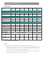
1
Swimming Pool Heat Pump
INSTALLATION AND USER MANUAL
Thank you for choosing our product and trusting our company.
This manual is to provide you with necessary information for optimal use and
maintenance, please read it carefully and keep it for subsequent use.
Content
I.
. Introduction
1
Safety precaution··············································································1
1
Important features of this product····················································1
3
Parameters of product range·····························································3
II.
. Installation guide
5
Transporting your unit·····································································6
5 6
Determining optimum installation position·········································
8
Water pipe connection······································································9
9
Electric connection··········································································10
10
Trial after first installation·······························································12
III.
. Operation guide
11
LED controller ···········································································13
12
Permanent display···········································································14
12
Common Setting··············································································14
13
Automatic on/off··············································································15
IV.
. Maintenance········································································16
14
V.
. Trouble shooting
15
Common faults················································································17
Failure code·····················································································18
16
Ⅰ. Introduction
Safety precaution
Caution: Danger of electric shock
Always switch off power supply
before working on the heat pump
and stop the hydraulic circuit.
- The swimming pool heat pump must be installed by a qualified electrician.
- Always install a differential protective device with a sensitivity of 30 mA on the
distribution unit before the electrical box.
- Always fit a circuit breaker for all active conductors on the power supply of the box.
- In the event of abnormal behavior (noise, smell, smoke), cut off the power supply
immediately and contact you reseller. Do not attempt to repair the system yourself.
- Keep the main power supply switch far from children.
- Rotating parts: Never remove the grid from the fan. Never place your hand or any other
object in the air inlet or outlet of the heat pump.
Important features of this product
This swimming pool heat pump is equipped with safeguards that will stop
operation to protect your unit automatically and display error code on the
LED controller in case of some events as following:
Water Flow Switch
The water flow switch contacts close when pressure is applied as pool water flows through
the titanium heat exchanger. Low flow rates as well as no flow will let these contacts open
and this will cause the unit to shut down. The LED display will read “EE3” if the water
pressure is not sufficient.
1
High / Low Refrigerant Pressure Switches
• The high-pressure switch senses the refrigerant pressure in the sealed refrigeration system
and shuts the heat pump down in the event unsafe operating pressures are reached. The heat
pump will automatically reset after the system pressure drops back to normal operating
pressures. When this switch is tripped, digital displays will read “EE1”
• The low-pressure switch senses the refrigerant pressure in the sealed refrigeration system
to protect against certain conditions that could be detrimental to compressor life. The switch
shuts the unit down in the event of loss of refrigerant or not enough refrigerants. The switch
automatically resets when the pressure rises to normal operating pressures. The display will
show “EE2” if this switch is tripped.
Low Ambient Temperature
If the air outside the heat pump is not warm enough to produce heat, the system will shut
down. The actual point at which your unit will shut down due to low temperature varies
depending on current weather conditions, the amount of sunlight reaching the heat pump.
The shutdown can occur anywhere within a wide range of temperatures, usually below 0
degrees. A shutdown occurs because low temperatures will activate the systems
low-pressure safeguard switch (digital controller will display a code “PP7”.) The unit will
start up again when the temperature has raised enough to reset this switch.
Time Delay
All models use a 3-minute time delay to prevent repeated tripping of the compressor thermal
overload, which is caused by attempting startup before system pressures are equalized. Any
interruptions, outside of power loss, will result in a 3-minute time delay.
2
Parameters of product range
Specification
Model
TH(C)P
TH(C)P
TH(C)P
TH(C)P TH(C)P
07L
10L
13L
17L
26L
TH(C)P
TH(C)P
26Ls
28Ls
Performance Condition: Air 26℃
℃, Water 26℃
℃
Heating capacity kW
7.5
10
13.5
17.5
26
28
33
C.O.P.
6.7
6.6
7
6.7
6.6
6.8
6.8
Performance Condition: Air 15℃
℃, Water 26℃
℃
Heating capacity kW
C.O.P.
5
7
10
12
16.5
17.5
22
4.8
4.7
5
4.7
4.5
4.8
4.6
Performance Condition: Air 35℃
℃, Water 28℃
℃
Cooling capacity kW
C.O.P.
Advised water flux m³/h
4.3
6
8
10
15
16
20
4
4
4
3.8
4
4.2
4
3-4
4-6
5-7
6.5-8.5
8-10
8-10
10-12
power
kW
1
1.45
2.0
2.6
3.7
3.7
4.78
Rated current
A
4.8
6.8
9.5
12.3
17
5.7
7.2
Rated
220-240V/1Ph/50Hz
Power supply
Water pipe in-out
spec
380-415V/3Ph/50Hz
50
50
50
50
40/47
50/59
68/77
78/88
50
50
50
mm
Net weight / Gross
weight
128/145 128/145
130/147
Kg
*C.O.P: Coefficient of performance
Note:
1.
Mode THP~ only have heat function and S refers to 3-phase.THCP~have heat and cool function.
2.
This product can work well under air temp +0℃~43℃. Performance cannot be guaranteed outside the
operating ranges and must take account the exterior conditions of use identified to select suitable mode
(such as location, area of swimming pool, and numbers of swimmer.)
3.
Above parameters are subjected to adjustment periodically for technical improvement with further notice.
Please refer to nameplate on each machine for accurate information.
3
Dimension:
E
C
F
H
G
I
A
D
B
A
B
C
D
E
F
G
H
TH(C)P07L
317
429
302
340
800
200
84
558
TH(C)P10L
317
590
302
340
960
280
84
658
TH(C)P13L
398
590
382
420
960
280
84
658
TH(C)P17L
398
590
382
420
960
380
84
758
TH(C)P26L
507
790
492
530
1160
600
84
958
TH(C)P26Ls
507
790
492
530
1160
600
84
958
TH(C)P28Ls
507
790
492
530
1160
600
84
958
Above data is subject to modification without notice
4
Ⅱ. Installation Guide
Attention!
This swimming pool heat pump must be installed by a skilled team.
Transport it in proper manner
1. Transport it in original package.
2. When moving the machine, do not lift the water nozzle since the titanium heat exchanger
in side the machine will be damaged. Please refer to the following wrong operation
picture:
!!Warning:
Because the machine is very heavy, the water
nozzle can not bear to be lifted during transit or
installation
The manufacturer cannot accept responsibility for damage incurred or repairs
necessitated due to improper handling of our equipment.
Determining Optimum installation position
The location of the swimming pool heat pump is very important for efficient operation,
think about the following factors when choose the proper place:
5
Avoidance of air recirculation
Easy for wire and pipe connection and Water pipe line of long water lines (not
longer than 10m.) from heater to pool.
Easy for maintenance.
Drainage of condensation.
Pay attention to the following points:
1. The heat pump must be installed OUTSIDE in a well ventilated place to avoid air
recirculation or in a place with adequate room area both for installation and
maintenance. Please refer to the following illustration:
A minimum of 300mm of clearance from walls, shrubbery, equipment, etc. is required around the entire
pump circumference. This allows for ample air intake. No less than 800mm clearance on the air outlet is
required to prevent re-circulation of air. We recommend not placing the unit underneath eaves, decks, or
porches, as this causes recirculation of discharged air, or the efficiency of the heater will be reduced or
even stopped.
Wrong installation
!!Warning:
Don’t install the heat pump close to a wall or
plants. And Never inside a closed building!
6
2. The heater should be located on a solid, level and non-corrodible structure that is
capable of supporting the weight of the heat pump. It must be fixed by bolts (M10) to
concrete foundation.
At least 300mm
!!Warning:
The machine must not be hung onto the
wall with soft pipe since the inlet/outlet
At least 300mm
union on the machine can’t hold weight.
At least 300mm
The machine must always be connected
with
hard
pipe!
At least 300mm
3. The heat pump should be far from any source of combustibles and corrosive material to
avoid any damage to this unit.
Never place heat pump near sprinkler systems, evaporation of acid or alkaline gas. If you live in an
oceanfront area, the heat pump should be placed out of direct spray of sand and salt, since this will also
clog, damage, and corrode the unit. You may consider protecting your heat pump by planting shrubbery
or a privacy fence between the unit and the prevailing beachfront wind.
4. When the machine is running, there will be condensation water discharged from the
bottom. Make sure there is enough space for water drainage.
TIPS:
HEAT PUMPS GENERATE WATER CONDENSATION DURING NORMAL
OPERATION. THIS SHOULD NOT BE MISTAKEN FOR A LEAK IN THE UNIT.
7
Water pipe connection
- The water flow through this machine needs to be driven by an appended water pump
(Prepared by the user). The recommended pump specification-flux is shown on the
product specification and Max. lift ≥10m;
- Pipe length between heat pump and swimming pool should not be longer than 10m.
Noted: The drawing is just for demonstration, and layout of the pipes for reference.
8
Electric connection
- Wiring must be handled by a professional technician according to the circuit diagram as
following.
- Connect the heat pump to appropriate power supply and the voltage should comply with
the rated voltage of each model stated on the specification.
- Make sure the machine is ground well.
- Always put leakage protector according to the local code for wiring (leakage operating
current ≤ 30mA).
-
Protect the circuit with a suitable circuit breaker or fuse.
Attention: The swimming pool heater must be earthed well.
9
Recommendation for protecting devices and cable specification
TH(C)P
TH(C)P
TH(C)P
TH(C)P
TH(C)P
TH(C)P
TH(C)P
07L
10L
13L
17L
26L
26Ls
28Ls
MODEL
Rated
Current
A
Rated
Residual
Action
Current
mA
Breaker
15
15
20
25
40
15
20
30
30
30
30
30
30
20
15
15
20
25
40
15
30
3×2.5
3×2.5
3×2.5
3×4
3×6
5×2.5
5×4
3×0.5
3×0.5
3×0.5
3×0.5
3×0.5
3×0.5
3×0.5
Fuse A
Power Cord
(mm2)
2
Signal cable (mm )
※
Above data is subject to modification without notice.
Note: The above data is adapted to power cord ≤ 10 m .If power cord is >10 m, wire
diameter must be increased.
The signal cable can be extended to 50 m at most.
Trial after first installation
Attention:
Always
Start the water pump before turning on this machine
Turn off this machine before turning off the water pump.
Inspection before connecting power supply
- Check the installation of the whole machine and the pipe connections according to the
pipe connecting drawing.
- Check the electric wiring according to the electric wiring diagram, and ground well.
- Make sure no blockage on the air inlet and outlet, or the efficiency of the heater will be
reduced or cause machine to stop operation.
Trial after connecting power supply
- Connect the machine with electric power supply, then relative information will display on
the LED controller.
(For Detail operation of LED controller, please refer to Chapter “Operation guide”.)
10
- Start the water pump before turning on the Machine to avoid any damage.
- Press power on/off on LED controller to turn on/off machine.
- During the first start of machine, please check if there is any water leakage in the piping
connection system. Then set suitable temperature.
- After the swimming pool heater runs, check if there is any abnormal noise or smell.
In any abnormal situation, such as serious noise, smell or smoking please cut the
power supply immediately and inform resellers, never try to repair it by yourself.
Special cases:
- In the event of an unexpected power cut, the heat pump will automatically restart. Check
the setting and adjust if necessary.
- In the event of an expected power cut, switch off the heat pump. When power is restored,
switch on the pump, check the settings and adjust if necessary.
- Always switch off the machine in stormy weather.
Ⅲ.Operation guide
LED controller
11
Power on/off
MODE
CLOCK
Set local time.
TIME OFF
Set the time required machine auto-stop.
Light A
Shows the auto-stop time being set.
TIME ON
Set the time required machine auto-work.
Light B
Shows the auto-work time being set.
COOL
Shows the cool mode (only available on the heat and cool machine)
HEAT
Shows the heat mode
MODE Key
Heat or cool mode selection (only available in heat and cool machine)
Down-ALLOW Set required temperature and time
UP-ALLOW
Set required temperature and time
LED screen
Display time, temperature and machine failure code
Permanent Display
A. The LED screen will display Time when the machine is turned off.
B. The LED screen will display Water temperature in swimming pool when the
machine is turned on.
Common setting
1.
. Heat/Cool Mode
Press the Mode button to switch from one mode to another.
(Available only in heat and cool machine.)
2.
. Required pool water temperature
It can be adjusted both when the machine is on or off.
A.
Press UP-ALLOW key
or DOWN-ALLOW key
to set to your required
pool water temperature.
B.
The numbers in the LED screen will flash during your operation.
C.
After five seconds, it will stop flashing and be saved, the LED screen will return
to the permanent display.
D.
When you want to check the temperature, press UP-ALLOW key
DOWN-ALLOW key
again to get it.
12
or
3.
. Time setting
It can be adjusted both when the machine is on or off.
A.
Press
key to set time according to your local time.
B.
Time on the LED screen flashes.
C.
Press
again then press UP-ALLOW key
or DOWN-ALLOW key
to
set hour.
D.
Before it stops flashing, press
DOWN-ALLOW key
E.
After setting, press
and then press UP-ALLOW key
or
to set minutes
and the water temperature will appears. 30 seconds later, it
will stop flashing and the LED screen will return to the permanent display.
Automatic on/off
This function can make the machine work or stop automatically in your required time.
1. Time on
A.
Press
to set timer on.
B.
When the indicator light is on and the time is twinkling, press
hour. Use
and
again to set
to adjust.
C.
Before the twinkling stops, press
to set minute .Use
and
to adjust.
D.
After adjusting, press “TIMER ON” and water temperature will be seen. 30
seconds later, the controller display will be back to the normal mode.
2. Time off
A.
Press
to set timer off.
B.
When the indicator light is on and the time is twinkling, press
hour. Use
and
again to set
to adjust.
C.
Before the twinkling stop, press
D.
After adjusting, press
to set minute .Use
and
to adjust.
and water temperature will be seen. 30 seconds later,
the controller display will be back to the normal mode.
3. Cancelling the automatic mode
A.
B.
Press
or
to cancel timer on and off.
When the number is twinkling, press
. When timer indicator light is off and
LED shows water temperature, the timer on and off is canceled.
C.
30 seconds later, the controller display will be back to the permanent display.
13
Ⅳ. Maintenance
Caution: Danger of electric shock
“Cut off” power supply of the heater before
cleaning, examination and repairing
A.
In winter season when you don’t swim:
1.
Cut off power supply to prevent any machine damage
2.
Drain water clear of the machine.
!!Important:
Unscrew the water nozzle of inlet pipe to let the water
flow out.
When the water in machine freezes in winter
season,the titanium heat exchanger may be damaged.
3.
cover the machine body when not in use.
B.Please clean this machine with household detergents or clean water, NEVER use
gasoline, thinners or any similar fuel.
C.Check bolts, cables and connections regularly.
14
Ⅴ. Trouble shooting
Common faults
Phenomenon
Possible reason
A. The fan motor stops automatically for defrost.
B. There will be sound from the solenoid valve when
A.Noticeable White vaporous
cold air or water.
machine starts or ends to defrost.
C. During machine working or just stopping, a sound like
water flow, in 2~3 minutes of starting the machine. This
Not
B. Plopping sound
failure
Sound comes from refrigerant flowing or water drainage
during dehumidification.
D. The plopping sound during the operation is caused by
expand on heating and contract on cooling of the heat
exchanger when temperature varies.
Automatic start or stop
Check whether there is mal-function on the timer.
Heat pump does not run
A. Power supply failure
B. Check manual power supply switch to make sure it is on.
C. Fuse burned.
D. If machine auto- protector has started (check failure
Recheck
code display on controller).
E. Check whether machine automatic on or off was set.
Running but not heating or
Check if there is blockage on air inlet and outlet of the unit.
cooling
Note: If the following conditions happen, please stop the machine and cut off the power
supply immediately, then contact your dealer:
The fuse is frequently broken or leakage circuit breaker jumped.
15
Failure code
NO.
Failure
code
Failure description
Action
1
EE 1
High pressure protection
Contact your dealer.
2
EE 2
Low pressure protection
3
EE 3
Low water pressure protection
Contact your dealer.
1. Check if there is no water
through the machine; make
sure the pump is on.
2. Or contact your dealer.
A.Single phase machine : failure
connection due to loose wire terminal of
4
EE 4
PROT2 on the PC board
B.Three phase machine :
Contact your dealer.
3 phase
sequence protection
5
PP 1
Pool water temp sensor failure
Contact your dealer.
a) Heat only type : Exhaust temp sensor
6
PP 2
failure
B.Cool and Heat type: Cooling coil pipe
Contact your dealer.
temp sensor failure
7
PP 3
Heating coil pipe temp sensor failure
Contact your dealer.
8
PP 4
Gas return temp sensor
Contact your dealer.
9
PP 5
Air temp sensor
Contact your dealer.
10
PP 6
Compressor exhaust overload protection
Contact your dealer.
11
PP 7
When the temperature < 0℃,auto stop
for protection (Not Failure )
16
Machine Auto-protection
H28-110218
17