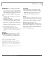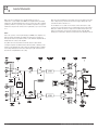
1
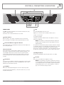
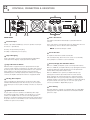
INSTALLATION AND OPERATION MANUAL
AMNG SERIES
Audio Power Amplifiers
AM2200NG
AM2600NG
IMPORTANT SAFETY INFORMATION
PRÉCAUTIONS DURANT UTILISATION
1. Read these instructions.
1. LISEZ ces instructions.
2. Keep these instructions.
2. Tenez ces instructions.
3. Heed all warnings.
3. Notez tous les avertissements.
4. Follow all instructions.
4. Suivez toutes les avertissements.
5. Do not use this apparatus near water.
5. N’utilisez pas ce produit près de l’eau (la piscine, la plage, le lac, etc.).
6. Clean only with dry cloth.
6. Nettoyez seulement avec une étoffe sèche.
7. Do not block any ventilation openings. Install in accordance with the
manufacturer’s instructions.
7. Ne bloquez aucuns troux de ventilation. Installez en accord avec
les instructions du manufacturier.
8. Do not install near any heat sources such as radiators, heat registers,
stoves, or other apparatus (including amplifiers) that produce heat.
8. N’installez près aucunes sources de chaleur comme radiateurs, registres
de chaleur, fours ou les autres équipements (y compris amplificateurs)
qui produisent la chaleur.
9. Do not defeat the safety purpose of the polarized or grounding-type plug.
A polarized plug has two blades with one wider than the other.
A grounding type plug has two blades and a third grounding prong.
The wide blade or the third prong are provided for your safety. If the
provided plug does not fit into your outlet, consult an electrician for
replacement of the obsolete outlet.
10. Protect the power cord from being walked on or pinched particularly
at plugs, convenience receptacles, and the point where they exit from
the apparatus.
11. Only use attachments/accessories specified by the manufacturer.
12. Use only with the cart, stand, tripod, bracket, or table specified by the
manufacturer, or sold with the apparatus. When a cart is used, use caution
when moving the cart/apparatus combination to avoid injury from tip-over.
13. Unplug this apparatus during lightning storms or when
unused for long periods of time.
14. Refer all servicing to qualified service personnel.
Servicing is required when the apparatus has been
damaged in any way, such as power-supply cord or plug
is damaged, liquid has been spilled or objects have fallen into the
apparatus, the apparatus has been exposed to rain or moisture, does
not operate normally, or has been dropped.
15. This appliance shall not be exposed to dripping or splashing water and
that no object filled with liquid such as vases shall be placed on the
apparatus.
16. Plug this apparatus to the proper wall outlet and make the plug to be
disconnected readily operable.
17. Mains plug is used as disconnected device and it should remain readily
operable during intended use. In order to disconnect the apparatus from
the mains completely, the mains plug should be disconnected from the
mains socket outlet completely.
18. WARNING: To reduce the risk of fire or electric shock, do not expose this
apparatus to rain or moisture.
19. An appliance with a protective earth terminal should be connected to a
mains outlet with a protective earth connection.
20. The apparatus should be disconnected from the mains completely before
speaker wiring. The speaker output should be proper protected from
direct contact and pay attention to speaker connections, terminals and
speaker wiring during normal operation.
9. Ne défaites pas le but de sécurité de la fiche polarisée ou base-type.
Une fiche polarisée a deux tranchants avec un plus large que l’autre.
Une fiche de base type a deux a deux tranchants et une troisième
pointe de base, le tranchant large ou la troisième pointe est fourni
pour votre sécurité. Si la fiche donnée ne conforme pas votre prise
de contact, consultez un électricien pour remplacement de la prise
de contact obsolète.
10. Protegez le cordon de secteur contre être marchée dessus ou pincez
en particulier aux fiches, aux douilles de convenance, et au point où ils
sortent de l’appareil.
11. Seulement utilisez attachements/accessoires spécifiés par le
manufacturier.
12. Utilisez seulement avec un chariot, un stand, un trépied, un support
ou une table indiquée par le manufacturier, ou vendue avec l’appareil.
Quand un chariot est utilisé, faites attention en déplaçant la combinaison
d’appareil/chariot pour éviter de se déséquilibrer.
13. Arrachez la fiche du dispositif durant éclair et orage ou
quand pas utilisé pour longues périodes de temps.
14. Référez au personnel qualifié de service pour toutes
réparations. La réparation est donnée quand le système
a été endommagé à n’importe façon, par exemple un fil
ou une fiche endommagé(e) de la source d’alimentation. Avoir été exposé
à pluie ou humidité, n’opère pas normalement, ou avoir été tombé.
15. L’appareil ne doit pas être exposé aux écoulements ou aux éclaboussures
et aucun objet ne contenant de liquide, tel qu’un vase, ne doit être placé
sur l’objet.
16. Branchez l’appareil à une source appropriée et faire que la prise à
débrancher soit facilement accessible.
17. La prise du secteur ne doit pas être obstruée ou doit être facilement
accessible pendant son utilisation. Pour être complètement déconnecté
de l’alimentation d’entrée, la prise doit être débranchée du secteur.
18. AVERTISSEMENT: Pour éviter le risque d’incendie ou de chocs électriques,
ne pas exposer cet appareil à la pluie ou à l’humidité.
19. Un appareil avec la borne de terre de protection doit être connecté au
secteur avec la connexiion de terre de protection.
20. Assurez-vous que l’appareil est hors tension avant de connecter les hauts
parleurs. Verifiez que la sortie des enceintes soit protégées contre un
contact physique. Respecter les polarités des terminaux ainsi que le
câblage des enceintes pendant le fonctionnement afin d’assurer une
utilisation sécurisee.
INTRODUCTION AND CONTENTS
AMNG SERIES
INTRODUCTION3
Congratulations on choosing Australian Monitor for your professional
amplification requirements.
FEATURES4
The AMNG Series Audio Power Amplifiers embrace all aspects of
a professional tool exhibiting quality, reliability and longevity. The
visual appearance, mechanical, electrical and sonic parameters
have been optimized using our dedicated manufacturing process.
CONTROLS, CONNECTORS & INDICATORS
5–6
INSTALLATION7–8
OPERATION9
The AMNG Series amplifiers are “2RU (3.5” or 88mm) high, 19”
(482mm) wide” rack mountable units.
MAINTENANCE10
Each channel of the amplifier comprises a balanced active input
with buffered attenuation through to the drive stage in turn feeding
a fan-cooled output stage. The amplifier operates from a high
current-capable switch-mode power supply.
SPECIFICATIONS11
These amplifiers have been specifically designed to deliver their
high power output with minimal distortion, and provide the critical
degree of control required by your speakers at high duty cycles for
extended periods.
Revision 1.3 June 2011
WARNING!
TO PREVENT FIRE OR SHOCK HAZARD, DO NOT USE THE PLUG WITH
AN EXTENSION CORD, RECEPTACLE OR OTHER OUTLET UNLESS THE BLADES
CAN BE FULLY INSERTED TO PREVENT BLADE EXPOSURE.
TO REDUCE THE RISK OF FIRE OR ELECTRIC SHOCK, DO NOT EXPOSE
THIS APPLIANCE TO RAIN OR MOISTURE.
TO PREVENT ELECTRICAL SHOCK, MATCH WIDE BLADE PLUG TO WIDE SLOT, FULLY INSERT.
CAUTION
RISK OF ELECTRIC SHOCK
DO NOT OPEN
The lightning flash with arrowhead symbol,
within an equilateral triangle, is intended
to alert the user to the presence of
uninsulated “dangerous voltage” within
the product’s enclosure that may be of
sufficient magnitude to constitute a risk
of electric shock to persons.
WARNING: TO REDUCE THE RISK
OF ELECTRIC SHOCK, DO NOT
REMOVE COVER (OR BACK).
NO USER SERVICEABLE PARTS INSIDE.
REFER SERVICING TO QUALIFIED
SERVICE PERSONNEL.
The exclamation point within an equilateral
triangle is intended to alert the user to
the presence of important operating and
maintenance (servicing) instructions in the
literature accompanying the appliance.
Rating plate and caution marking are marked on the back enclosure of the apparatus
AM2200NG & AM2600NG INSTALLATION AND OPERATION MANUAL
PAGE 3
FEATURES & PROTECTION FEATURES
FEATURES
Custom designed, 2RU heavy duty steel chassis
Built in limiter circuit
Front carry handles
Stereo, bridged or parallel operation
Symmetrical layout – even-weight distribution
Binding post and 4 pole speaker output connection
Class G operation
VU meter
High efficiency switch mode power supply
Output clip indication
Efficient front to back cooling
Multi-role output fault indication
Variable speed axial fans
High-quality, close-tolerance components throughout
Balanced inputs and buffered attenuators
Lightweight
Input signal strapping (loop through) connectors
Signal ground lift switch
PROTECTION FEATURES
Suppression of inrush current at mains turn-on
Input muting at turn-on
Input overvoltage protection
Radio-frequency interference suppression
Short-circuit protection and indication
High overload mains breaker
Thermal sensing
PAGE 4
AM2200NG & AM2600NG INSTALLATION AND OPERATION MANUAL
CONTROLS, CONNECTORS & INDICATORS
8
6
5
1 7 3
FRONT PANEL
The AMNG Series differ only slightly across all models and all share the same
features on their front panels.
The functions of the controls and indicators are as follows:
1 Power Switch
Press the switch to up for power on and down for power off. At start-up
(turn-on), the input to the amplifier is muted for approximately two seconds.
2 Australian Monitor Logo/On Indicator
The Australian Monitor logo will illuminate and indicates that the amplifier is on
and receiving mains power.
3 Fault Indicator
This red LED indicates a problem with the amplifier or that it has over heated.
In the advent of a thermal overload, the internal operating temperature of one
or both amplifier channels has exceeded a safe level of operation and the
channels will be automatically muted. The fans will continue to run and once
the affected channel/s have cooled, they will unmute and return to normal
operation.
2
4
6 Clip
This red LED will illuminate when clip occurs.
Clipping can occur under extreme operating conditions such as:
complex or very low loads
over driving the amplifier
It should be noted that the minimum load for the amplifier is 2 ohms per
channel (4 ohm bridged).
NOTE: The amplifier is not damaged by running into clipping, but
speakers may be. To maximise the life of your speakers, try to keep
clipping infrequent.
The clip detection circuit works by using the feedback circuit where the input
is continually compared to the output. When the input differs from the output
either due to rail clipping or current limiting the clip circuit is triggered.
This point also controls the voltage limiter so the voltage will limit at precisely
the clip point no matter what the load is or where the mains voltage level is.
7 Bridge Indicator
This amber LED will illuminate when the input switch is set to bridge.
8 Fan Grill
4 Attenuator
Level control for your amplifier is provided by a potentiometer on the front panel
and indicates gain. There are two controls on all AMNG models. Each control is
labelled for the channel which it operates.
5 VU Meter
This is where air is drawn into the amplifier for cooling.
NOTE: You should always ensure that the fan Gril is kept clean and
free from the build up of dust and lint. This will ensure longer operation
of your amplifier and reduce the possibility of it prematurely going into
thermal shutdown mode. See the section “Installation – Cooling” on
page 7 for recommended cooling procedures.
This is a blue LED lamp which displays the level of the output stage signal.
The attack and decay time (ballistics), of the status circuit are those of a Peak
Programme Meter (P.P.M.)
AM2200NG & AM2600NG INSTALLATION AND OPERATION MANUAL
PAGE 5
CONTROLS, CONNECTORS & INDICATORS
11
9
16
10
17
REAR PANEL
9 Balanced Input
A female 3-pin combined XLR/TRS type connector is provided on each input:
Pin 1/Sleeve = Signal Ground;
Pin 2/Tip = Hot (non-inverting or in phase);
Pin 3/Ring = Cold (inverting or reverse phase).
10 Signal Strapping
A male 3-pin XLR type connector is provided and wired in parallel with the
female input XLR for strapping / looping signal between amplifiers.
11 Signal Ground Lift Switch
When this switch is engaged it disconnects signal ground from the input
connectors on both channels. It is intended to be used when “hum” is caused
by earth loops (due to different ground potentials between source equipment
and the amplifier) or stray magnetic field pick up on the input ground/
shield wiring. (It does not interrupt signal ground continuity on the strapping
connector). The amplifier should be turned off before engaging this switch!
12 Binding Post Outputs
Touch proof binding posts (banana jacks) are provided for speaker output
termination with banana plugs or bare wire. The red post is used as positive
and the black post is used as negative. For bridge connection, use only the red
posts.
13 Speaker Output Connector
A 4 pole speaker connector is provided as an additional speaker output.
This standard of loudspeaker-to-amplifier connection allows access to both
channels of the amplifier via the one connector for bi-amp applications.
Channel-A is considered the dominant channel and has both channels wired to
the speaker connector. See the installation section of this manual for detailed
information on speaker connector wiring.
PAGE 6
12
15
13
14
14 Mains Connection
Your amplifier is fitted with an internationally recognised IEC mains inlet
connector.
Please ensure that the connecting mains lead for use with the IEC connector is
of an approved type and is of sufficient current carrying ability.
NOTE: Your unit must always be earthed!
15 Circuit Breaker
The amplifier is fitted with a resettable circuit breaker.
If the circuit breaker trips, allow 3 mins for the contacts to reset thermally
before pushing the reset button to reset it mechanically.
16 Stereo/Bridge/Parallel Mono Switch
When set to STEREO, your amplifier operates as two independant channels.
When set to PARALLEL, your amplifier will only accept signal applied to Channel
A’s input XLR. Channel B’s output signal will come from A’s input but both
channels will have independent attenuator control.
When set to BRIDGE mode of operation your amplifier will only accept
signal applied to channel A’s input XLRs and the level of both channels
will be controlled by the channel A attenuator. The output from channel B
will automatically be of the opposite polarity (reversed phase) and speaker
termination should be sourced from the red binding-post outputs. Alternatively,
the speaker could be connected to poles 1+ & 2+ of the 4 pole speaker
connector (see Installation – Output Wiring on page 7).
17 Gain Setting
This switch adjusts the sensitivity of your amplifier. When set to 0dB a 0dBu
signal applied to the input with the attenuator at max will deliver maximum
power to the output.
AM2200NG & AM2600NG INSTALLATION AND OPERATION MANUAL
INSTALLATION
Power Requirements
When wiring for an unbalanced source:
Power consumption for your model of the AMNG Series amplifier is indicated on
the rear panel for maximum output.
Pin 1/Sleeve = GROUND/SHIELD
Ensure that your mains voltage is the same as the rear panel mains voltage
marker (+/- 10%).
Mounting
Your amplifier is designed for standard 19” (482mm) rack mounting and
occupies 2 EIA rack units 3.5” (88mm). The mounting centres are:
Vertical: 3.0” (76.2mm)
Horizontal: 18.2” (461.2mm) to 18.7” (473.8mm).
The slots in the mounting flange will accept bolt diameters up to 1/4”
(6.35mm).
We recommend that you provide additional support for the amplifier, especially
if road use is planned, as the weight could bend some rack frames. This
support can be provided by secure shelving on support rails.
Pin 2/Tip = HOT (in phase with the amplifier’s output),
Pin 3/Ring = GROUND/SHIELD (joins to pin 1).
NOTE: In-line XLR connectors often have a termination lug that
connects directly to the chassis of the connector.
IMPORTANT: Do not link this lug to pin 1 at the amplifier’s input as
it will defeat the amplifier’s input grounding scheme.
Output Wiring
When wiring to your speakers always use the largest gauge wire your
connector will accept. The longer the speaker lead, the greater the losses will
be, resulting in reduced power and less damping at the load. We recommend
using a heavy duty, two core flex (four core flex if bi-amping) 10 to 12 gauge
(2mm2 to 2.5mm2 or 50/0.25 or equivalent) as a minimum.
Binding Post Outputs
Cooling
Your AMNG Series amplifier is cooled by an axial fan which draws cool air from
the front of the amplifier and expels the heated air out the rear of the amplifier.
These amplifiers offer variable speed fans which run at half speed up to to full
speed when the internal heatsink temperature exceeds 60° C (128° F).
An unrestricted airflow into and out from the amplifier must be provided.
Any restriction of the air flow will cause heat to build up within the unit and
possibly force the unit into its thermal shutdown mode.
If the amplifiers are to be operated in an environment where the airflow is
restricted such as sealed racks, the cooling should be supplemented by extra
cooling fans to evacuate the heated air and aid the flow of cool air through
the unit.
When terminating to the 4 mm binding post (banana jack) output connectors,
banana plugs or bare wires can be used. The red terminal is positive and the
black terminal is negative (ground).
If running in BRIDGE mode, only the red binding posts are used.
When bridging, Channel A provides the positive output to the load and channel
B provides the negative output to the load.
Speaker Outputs
When using the 4 pole speaker connector for speaker output, use only the
mating 4 pole in-line connector. This connector is designed so that both
channels can be fed from a single connector.
Two speaker connectors are provided on the amplifier.
Input Wiring
IMPORTANT: Do not directly connect pin 1 on the amplifier’s input
or strapping XLR, to the amplifier’s chassis, speaker ground or power
ground!
WARNING: Input signal ground is not to be used as a safety
ground (earth).
The input to your amplifier is a balanced 3-pin configuration and requires all
three pins to be connected. Only high quality twin-core shielded cable should
be used.
When wiring for a balanced source, the connector going to the input of your
amplifier should be wired as follows:
The ”Channel A” speaker connector actually carries both channel A and channel
B outputs (see Speaker Connector Wiring Diagrams).
The ”Channel B” speaker connector carries the Channel B output only.
This arrangement allows you the option of connecting to the outputs separately
or together. Connecting through a single connector has the advantage of
minimising connections, preserving phasing and simplifying channel allocation,
which is particularly important when bi-amping or in bridge mode.
IMPORTANT: Do not overload your amplifier by connecting the
channel B output twice!
Pin 1/Sleeve = GROUND / SHIELD.
Channel A is used as the “dominant” channel and when sourcing a dual output
from Channel A, the following standard should normally be used (depending on
speaker system wiring):
Pin 2/Tip = HOT (In Phase - non inverting).
Channel A = Left or Low Frequencies.
Pin 3/Ring = COLD (Reverse Phase - inverting).
Channel B = Right or High Frequencies.
When wiring from an unbalanced source you must ensure that pin 3 is
connected to pin 1 (input ground), either by linking the pins in the input
connector or by the source equipment’s output wiring.
When in bridge mode:
AM2200NG & AM2600NG INSTALLATION AND OPERATION MANUAL
Pin 1+ = Bridge Output Positive
Pin 2+ = Bridge Output Negative
PAGE 7
INSTALLATION
Speaker Connector Wiring Diagram
Hum Problems continued
This is by far the most common cause of hum, and it occurs when source
equipment and the amplifier are plugged into different points along the safety
earth where the safety earth wiring has a current flowing through it. The current
flowing through the wire produces a voltage drop due to the wire’s resistance.
This voltage difference between the amp earth and source equipment earth
appears to the amplifier’s input as a signal and is amplified as hum.
There are three things you can do to avoid earth loop problems:
Ensure the mains power for the audio system is “quiet” i.e. without equipment
on it such as air-conditioning, refrigeration or lighting which may generate noise
in the earth circuit.
Ensure all equipment within the system shares a common ground/ safety
earth point. This will reduce the possibility of circulating earth currents, as the
equipment will be referenced to the same ground potential.
Ensure that balanced signal leads connecting to the amplifier are connected to
earth at one end only.
Signal Ground-Lift Switch
When proper system hook-up has been made, you may still have some hum
or hum related noise. This may be due to any of the previously mentioned
gremlins.
Hum Problems
Most equipment is designed for minimum hum when used under ideal
conditions. When connected to other equipment, and to a safety earth in an
electrically noisy environment, problems may occur.
The three ”E”s of hum and hum related noise which can plague your audio
system are:
a) Electrostatic radiation,
b) Electromagnetic radiation,
c) Earth loops
Electrostatic radiation capacitively couples to system elements, causing an
interference voltage that mainly affects higher impedance paths, such as
amplifier inputs. The source is generally a nearby high voltage, such as a mains
lead or a speaker lead. The problem can usually be reduced by moving the
offending lead away, or by providing additional electrostatic shielding (i.e. an
earthed conductor which forms a barrier to the field).
Electromagnetic radiation induces interference currents into system elements
that mainly affect lower impedance paths. Radio transmitters or stray magnetic
fields from mains transformers are often the cause of this problem. It is
generally more difficult to eliminate this kind of interference, but again, moving
the source away or providing a magnetic shield (i.e. a steel shield) should help.
Your AMNG Series amplifier has a “Signal Ground Lift” switch which
disconnects the input ground wiring from the amplifier. A substantial drop in
hum and/or hum related noise can result from the judicious use of this switch.
NOTE: If the input ground lift switch is used, you must ensure adequate
shielding of the input wiring. If the signal source equipment does not
provide adequate shielding (i.e. a definitive connection to ground), you
must disconnect the shield from the input connector’s ground pin (Pin-1)
and re-connect it to the ”drain” contact on the input connector. This
willensure the shield on your input wiring actually goes to the amplifier
chassis and subsequently to earth.
IMPORTANT: Do not connect pin-1 directly to the drain connection.
You will defeat the amplifiers internal grounding scheme and possibly
cause instability to the amplifier.
Always ensure that your amplifier is off and the attenuators are down
when you engage this switch. This switch should only be used when the
amplifier is operated from a balanced signal source.
NOTE: Be wary of quasi-balanced outputs, these are often no more
than floating unbalanced outputs.
Earth loops can arise from the interfacing of the various pieces of equipment
and their connections to various safety earths.
PAGE 8
AM2200NG & AM2600NG INSTALLATION AND OPERATION MANUAL
OPERATION
IMPORTANT: All signal source equipment should be adequately
earthed. This not only ensures your safety but everybody else’s as well.
Faults can and do occur in mains connected equipment where the
chassis can become “live” if it is not properly earthed. In these instances, the fault in a “floating” (ungrounded) piece of equipment will look for the
shortest path to ground, which could possibly be your amplifier’s input. If
the fault current is large enough, it will destroy the input to your amplifier
and look for the next available path, which may be you!
Before making any connections to your AMNG Series amplifier, observe the
following:
Ensure the mains voltage supply matches the label on the rear panel of
your amplifier (+/- 10%).
Ensure that the power switch is OFF.
Ensure that all system grounds (earth) are connected from a common
point. Avoid powering equipment within a system from multiple power
sources that may be separated by large distances.
Check the continuity of all interconnecting leads to your amplifier; ensure
that there are no open or short circuited conductors.
Ensure that the power handling of your load (speakers) can adequately
cope with the power output of the amplifier.
Before operating your AMNG Series amplifier, ensure that:
The attenuators are at the “OFF” position (fully anticlockwise).
The GROUND LIFT Switch is not engaged (should be in the “out” position).
Level Matching
The normal operating position for the attenuator is the max position (fully
clockwise, no attenuation). In this position the amplifier operates at full gain.
Turning the attenuator back (anticlockwise) reduces the input sensitivity.
NOTE: If full power output is required, you should operate your
amplifier with the front panel attenuator above the half way (12o’clock)
position, otherwise clipping of the input circuitry and its resultant
distortion will occur before full output power is achieved.
Sensitivity
Your amplifier is a linear device operating with a fixed input to output voltage
gain (less attenuation). The maximum output voltage swing is determined by the
applied mains voltage, load, load type and the duty cycle of the applied signal.
The input sensitivity for your AMNG Series amplifier when the attenuator is at
maximum position (fully clockwise) is nominally:
0dBu (0.775 volts in) for rated power into a 4 ohm load.
Each channel of your AMNG Series amplifier has a nominal balanced input
impedance of 20kOhms (@1kHz) and should not present a difficult load for any
signal source.
Your signal source (i.e. the equipment feeding signal to the amplifier) should
have an output impedance of 600 Ohms or lower to avoid unwanted high
frequency loss in the cabling.
Input overload occurs at +20.5dBu(8.25volts).
The BRIDGE Switch is not engaged if you are not running the amp in
bridged mode.
Powering Up
REMEMBER: The amplifier should be the last piece of equipment
that you turn on and the first piece of equipment that you turn off.
We recommend turning the attenuators on your amplifier down when
turning the unit on.
When you power up your AMNG Series, your amplifier goes through an
initialising period before it will accept signal. The Inrush Current Suppression
(ICS) circuit is in operation for the first 0.2 seconds. This limits the mains
current, to prevent ”nuisance-tripping” of circuit breakers.
During this period you will hear a couple of relays “click”, indicating mains is
now directly applied to the amplifier and the signal path is connected.
While the ICS circuit operates there is also a 30dB mute on the signal input.
After two seconds this mute will release, allowing any applied signal to pass
un-attenuated.
When switching the amplifier off, wait a couple of seconds before switching the
amplifier on again. This allows the ICS circuit to reset.
AM2200NG & AM2600NG INSTALLATION AND OPERATION MANUAL
PAGE 9
MAINTENANCE
Only competent or qualified persons should attempt any service or
maintenance of your amplifier. Your AMNG Series amplifier will need minimal
maintenance. No internal adjustments need to be made to the unit to maintain
optimum performance. To provide years of unhindered operation we suggest a
maintenance inspection be carried out on a regular basis, say every 12 months
or so.
Fans
Over time, dust may build up on the leading edge of the fan blades and reduce
their cooling efficiency. The time taken for this to happen will depend on the
environment and the amount of use.
The fan blades are accessible once the lids are removed and can be easily
cleaned. You need only hold the fan rotor still and wipe the dust off the blades.
Many users stall the fan and use compressed air to blow the dust off the fan
blades. It is important to note that the fan blades must be held still whilst
blowing air over the blades otherwise you may burn out the bearings in the fan.
Due to the openness of the air path through your AMNG Series amplifier, very
little dust should settle within the amplifier. The unit has been designed so
that any dust and/or foreign particles that do settle within the amplifier will not
unduly hinder the cooling of the amplifier.
The grill in front of the fans will act to limit the amount of dust and lint
entering the amplifier. You will find in time that there will be a build up of dust
and lint on the grill which may start to hinder the airflow through the amplifier.
You should periodically remove the dust and keep the grill clean. Removal of
dust from the rear grill will also aid cooling.
SPEAKER
CONNECTOR
(BRIDGE)
PAGE 10
AM2200NG & AM2600NG INSTALLATION AND OPERATION MANUAL
SPECIFICATIONS
AM2200NG
Output Power 1% THD @ 1kHz
2ohm single
channel
2ohm both
channels driven
4ohm
8ohm
1200W
1100W
700W x 2
450W x 2
2200W
1400W
Stereo
Bridged
Distortion (re 4ohm, 1dB below clip)
THD (@ 1kHz)
0.1%
Input Impedance
20kohms
Input Sensitivity
-6/0/+6dBu
Signal/Noise Ratio
100dB
Damping factor
(@ 1kH re 8 ohms)
300:1
Frequency Response
(+/0.5dB)20Hz–20kHz
Thermal Dissipation
Both channels, 2ohm 1/8th power
Current Draw
Both channels driven, 2ohm load, 230Vac 1/8th power
780W (2661btu/hr)
5.7A
Dimensions (H x W x D)
88mm x 482mm x 460mm
Weight
11kg
Shipping Dimensions (H x W x D)
190mm x 600mm x 560mm
Shipping Weight
13kg
AM2600NG
Output Power 1% THD @ 1kHz
2ohm single
channel
2ohm both
channels driven
4ohm
8ohm
1500W
1300W
900W x 2
550W x 2
2600W
1800W
Stereo
Bridged
Distortion (re 4ohm, 1dB below clip)
THD (@ 1kHz)
Input Impedance
Input Sensitivity
0.1%
20kohms
-6/0/+6dBu
Signal/Noise Ratio
100dB
Damping factor
(@ 1kH re 8 ohms)
300:1
Frequency Response
(+/0.5dB)20Hz–20kHz
Thermal Dissipation
Both channels, 2ohm 1/8th power
Current Draw
Both channels driven, 2ohm load, 230Vac 1/8th power
Dimensions (H x W x D)
Weight
Shipping Dimensions (H x W x D)
Shipping Weight
AM2200NG & AM2600NG INSTALLATION AND OPERATION MANUAL
920W (3139btu/hr)
6.8A
88mm x 482mm x 460mm
12kg
190mm x 600mm x 560mm
15kg
PAGE 11
ENGINEERED BY AUSTRALIAN MONITOR
Address: 1 Clyde Street, Silverwater, Sydney NSW 2128 Australia. Private Bag 149, Silverwater NSW 1811 ABN 78 001 345 482
Website: www.australianmonitor.com.au International enquiries email: [email protected]
DISTRIBUTED IN AUSTRALIA AND NEW ZEALAND BY HILLS SVL www.hillssvl.com.au
NSW P: 02 9647 1411
E: [email protected]
QLD
ACT
P: 07 3852 1312
P: 02 6260 4544
E: [email protected] E: [email protected]
WA
P: 08 9204 0200
E: [email protected]
VIC
P: 03 9890 7477
E: [email protected]
SA
NZ
P: 08 8408 8300
P: 09 415 9426
E: [email protected] E: [email protected]