1
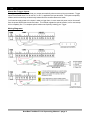
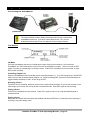
BooBox FlexMax
OPERATING MANUAL
V1.1 (Aug 14, 2011)
6 Oakside Court
Barrie, Ontario L4N 5V5
Tel: 1-877-815-5744 or 905-803-9274
www.frightideas.com
1
2
Table of Contents
Getting Familiar with your FlexMax ...................................................................................................................3!
Power Supply .......................................................................................................................................................4!
Selecting your Power Supply ..........................................................................................................................4!
Connecting your Power Supply .......................................................................................................................4!
Sharing the Power Supply with other Devices ................................................................................................4!
Solid-State Outputs .............................................................................................................................................5!
About the Solid-State Outputs.........................................................................................................................5!
Replacing the Solid-State Driver Chip.............................................................................................................5!
Controlling D.C. Solenoids and Relays ...........................................................................................................6!
Controlling an A.C. Outlet ...............................................................................................................................6!
Controlling a Fog Machine ..............................................................................................................................6!
Controlling Large Solenoids and Relays .........................................................................................................7!
BooBox Output Accessories ...........................................................................................................................7!
BooBox Expansion Connector Pinouts ...........................................................................................................8!
Trigger Inputs .......................................................................................................................................................9!
About the Trigger Inputs..................................................................................................................................9!
Wiring Diagrams..............................................................................................................................................9!
Optically Isolating your Trigger......................................................................................................................10!
Audio Connections ............................................................................................................................................11!
Line Out Connection .....................................................................................................................................11!
Mix In Connection .........................................................................................................................................11!
Mix In Microphone Setup ..............................................................................................................................12!
Amplified Speaker Outputs ...............................................................................................................................13!
About the Internal Amplifier ...........................................................................................................................13!
Two Speaker Wiring Diagram .......................................................................................................................13!
Four Speaker Wiring Diagrams .....................................................................................................................13!
DMX .....................................................................................................................................................................15!
About DMX ....................................................................................................................................................15!
DMX Connection ...........................................................................................................................................15!
Typical DMX Chain .......................................................................................................................................16!
Setting DMX Channels ..................................................................................................................................16!
FlexMax DMX Channel Assignments............................................................................................................16!
FlexMax Operation .............................................................................................................................................17!
Sounds ................................................................................................................................................................18!
How the FlexMax uses Sounds.....................................................................................................................18!
Converting Sounds to MP3 ...........................................................................................................................18!
Copying Sounds to the BooBox’s SD Card ...................................................................................................18!
BooBox SD Card Sound File Locations ........................................................................................................18!
Programming Animation and Settings with the ScareMaster .......................................................................19!
Connecting the ScareMaster.........................................................................................................................19!
The Basics ....................................................................................................................................................19!
Programming DMX Animation.......................................................................................................................20!
Advanced Scene Options..............................................................................................................................21!
BooBox Setup ...............................................................................................................................................22!
Troubleshooting ................................................................................................................................................23!
Specifications ....................................................................................................................................................23!
BooBox FlexMax FI-216 Operating Manual - page 2
1
2
Getting Familiar with your FlexMax
Solid-State Outputs
Speaker Outputs
Audio Status LEDs
SD Card Slot
Line Out
MP3 Vol
Mix In
Mix Vol
Play Button
Trigger Inputs
DMX In/Out
Power
Servo Outputs
Power Connector
ScareMaster
Connector
Expansion Connector
CONNECTIONS AND CONTROLS
Animation outputs (12 or 24 VDC depending on power supply).
50 watt (25x2) stereo amplified audio output.
These LEDs illuminate when sound is playing. One represents the left
channel of the BooBox’s MP3 Decoder, one the left channel of Mix In.
Socket for the SD card which holds the sound and animation.
Line-level output of the BooBox’s MP3 decoder.
Controls the Speaker Output volume of the BooBox’s MP3 decoder.
Line-level input mixed into the amplified Speaker Output. This audio will not
be mixed into the Line Out output.
Controls the Speaker Output volume of the Mix In audio.
Tap to play the input 1 scene, or tap to stop any playing scene.
Optically-Isolated trigger inputs for scene triggering.
DMX connector for controlling lighting or any other DMX device.
12-24 VDC power input. Connected internally to the 2.1mm power input.
RC Servo outputs. These are controlled with DMX channels 4 and 5.
12-24 VDC power input. Connected internally to the Power terminal block.
Connection for the ScareMaster animation programmer.
Easily control our relay boards or AC Relay packs using this connector.
BooBox FlexMax FI-216 Operating Manual - page 3
1
2
Power Supply
Selecting your Power Supply
The FlexMax requires a 12 or 24 volt DC power supply. When using 24 volts, the power supply must be
regulated. The Flex does not ship with a power supply, you must purchase your own supply based on the
required voltage and current of your outputs. We highly recommended using a 24 volt power supply. This will
get you the most wattage from the audio amplifier and enable you to use larger solenoids without exceeding the
maximum current capacity of the solid-state outputs. It will however require that all the devices connected to
your outputs be rated for 24 volts.
Sizing Your Power Supply
To size a supply you must calculate for the worst-case scenario. Add up the wattage for the most outputs that
will be on at any one time. If you are using the internal amplifier, add at least 25 watts if you’re playing at a
moderate volume, or 50 watts if you’ll be turning it up really loud. Then add 5 watts for the FlexMax.
So for example, let’s say you have 10 x 6 watt 24 volt solenoids, but only 4 are on at any given time, and you
want to use the amplifier at a moderate volume.
24 watts (4 x 6 watt solenoids) + 25 watts (amplifier) + 5 watts (FlexMax) = 54 watts
You’d need a 24 volt regulated DC supply rated for at least 54 watts.
DO NOT use unregulated 24 volt power supplies. They will exceed the maximum
24 volt input limit and damage the internal amplifier.
Connecting your Power Supply
The power supply can be connected to the 2.1mm barrel connector or the terminal block.
Sharing the Power Supply with other Devices
The power terminal block and barrel connector are internally connected. This makes it easy to share the power
supply with another device provided your power supply has enough wattage to go around.
BooBox FlexMax FI-216 Operating Manual - page 4
1
2
Solid-State Outputs
About the Solid-State Outputs
The solid-state outputs are ideal for reliably controlling relays and solenoids. They cannot be used to directly
control A.C. powered or contact-closure devices like a relay can. However, unlike relays, they have no moving
parts that will wear out over time. They also have feedback suppression diodes built-in to absorb the nasty
noise relays and solenoids release the moment they are turned off.
To use the solid-state outputs reliably you must be mindful of their current limitations. Each output can handle
500mA of current regardless of the supply voltage, this calculates to 6 watts at 12 volts, or 12 watts at 24 volts.
This is why we recommend 24 volt supplies, you will be able to use much larger solenoids without exceeding
the 500mA limit.
Internal Fuses
In addition to the 500mA per output limit, there are also two internal fuses, one for outputs 1-8, and one for
outputs 9-16. These fuses will temporarily open if the sum of the current flowing through either set of outputs is
around 1.1A for too long. The fuse will automatically reset once the excessive draw has been removed. This
may sound like a limitation, but not really. Most solenoids draw about 5 watts on average, at 24 volts that’s
210mA per solenoid. So four valves could be left on continuously without fear of overloading.
Do Not Short The Outputs!
The internal fuses will protect the solid-state driver chips from being overloaded, but they are not fast enough to
protect them from direct shorts. Double-check your wiring before you power up. If you see a small puff of
smoke or smell something nasty, you may need a new driver chip.
Replacing the Solid-State Driver Chip
If some or all of the outputs are no longer working, or they are all on no matter what you do, the solid-state
driver chip likely needs to be replaced.
Buying a New Chip
The driver chip used in the BooBox is a very popular chip used by many manufacturers. We carry them on our
website, but they will almost certainly be available at a local electronic component supplier if you’re in a jam.
You can also purchase them from online suppliers like Digi-Key and Mouser.
The chip’s part number is ULN2803A. Various manufacturers make compatible parts with almost identical part
numbers, although there may be a few more letters after the A. As long as the chip package is DIP and it looks
like the picture below, it will almost certainly work just fine.
Replacing the Solid-State Driver Chip
Replacing the chip is a somewhat delicate process. The best way to learn how to do it correctly is to watch the
video on our website. Search for driver chip in the search box and click on the first hit to see the product details
and video.
BooBox FlexMax FI-216 Operating Manual - page 5
1
2
Controlling D.C. Solenoids and Relays
Use only solenoids or relays rated at the same voltage as your power supply. If your device draws more than
the 6 watts at 12 volts or 12 watts at 24 volts then see Controlling Large Solenoids and Relays.
Controlling an A.C. Outlet
Solid-state outputs cannot be used to directly control A.C. devices. These must be controlled through a relay
as shown below. If you have many of these devices to control, see our Relay Board or A.C. Relay Packs in
BooBox Output Accessories.
Controlling a Fog Machine
Standard fog machines can be controlled by hacking the remote and wiring the button to a relay. More
expensive fog machines can be connected to the BooBox with DMX.
BooBox FlexMax FI-216 Operating Manual - page 6
1
2
Controlling Large Solenoids and Relays
Devices that aren’t compatible with the solid-state outputs can be controlled through a relay. If the device being
controlled is a solenoid or relay, it’s recommended to install a diode or capacitor across the leads, as close to
the device as possible. Use a diode if the device is D.C., or a capacitor if the device is A.C. This will absorb
the feedback these devices create when they are turned off and the energy stored in their coil is released.
Without this part you may notice quirky behavior in nearby electronics, including the BooBox or ScareMaster.
Recommended Parts
Diodes – Standard 1N4001-1N4004 diode, Radio Shack part numbers 276-1103 or 276-1102.
Caps – 0.1uF capacitor rated for at least 200 volts. Radio Shack part numbers 272-1053 or 272-1051.
BooBox Output Accessories
These output accessories make it convenient to control devices that aren’t compatible with the BooBox’s solidstate outputs. They connect easily to the expansion connector on the side of the BooBox and instantly mirror
the activity on outputs 1 thru 8. Solid-state outputs 1 thru 8 on the BooBox can be used simultaneously with
any of these accessories, however they will both turn on and off at the same time.
If you are interested in dimming lighting rather than just turning it off and on see DMX.
Relay Boards
AC Relay Pack 4
AC Relay Pack 8
BooBox Output Accessories
FI-324-12 (12 volt)
Each relay board has four 10 amp relays. Connect up to two in
FI-324-24 (24 volt)
series to get eight relays. Available in 12 or 24 volts, buy the
model that matches your power supply.
FI-304
Provides four 120 volt A.C. duplex receptacles.
FI-308
Provides eight 120 volt A.C. duplex receptacles.
BooBox FlexMax FI-216 Operating Manual - page 7
1
2
BooBox Expansion Connector Pinouts
The expansion connector is really just another way to connect to the BooBox’s solid-state outputs. Rather than
connecting a bunch of wires to the terminal blocks, a specifically made wiring harness can be plugged into the
expansion connector, effectively making all these connections at once.
We use this connector to make connecting to our BooBox Output Accessories quick and painless. If you’d like
to utilize this connector for your own applications, the pinouts are shown below. If you’ve used a MiniBrick,
these pinouts might look familiar.
EXPANSION CONNECTOR PINOUTS
PIN
CONNECTION
1
Ground
2
Output 8
3
Output 7
4
5
Output 6
6
Output 4
7
Output 3
8
Output 2
9
Output 1
10
+ Connection (12 – 24 VDC Fused at 1 Amp)
Output 5
BooBox FlexMax FI-216 Operating Manual - page 8
1
2
Trigger Inputs
About the Trigger Inputs
The trigger inputs are used to activate your scenes automatically when a sensor picks up movement. Trigger
Inputs are activated when 5 to 24 volts A.C. or D.C. is applied to the input terminals. The inputs are opticallyisolated, which means they are electrically isolated from the sensitive electronics inside.
You’ll need to supply power to the inputs in order to trigger them, in most cases this power can be “borrowed”
from the power terminal block as shown below. This method negates the optical isolation, but for most setups
this is completely fine. For complete optical isolation see Optically Isolating your Trigger.
Wiring Diagrams
BooBox FlexMax FI-216 Operating Manual - page 9
1
2
Optically Isolating your Trigger
In situations where the FlexMax is being triggered by another controller on a separate power supply, or by a
pushbutton or sensor that’s located a significant distance from the controller, it’s best to take advantage of the
optical-isolation.
BooBox FlexMax FI-216 Operating Manual - page 10
1
2
Audio Connections
Use only stereo audio cables when
connecting to the FlexMax.
Line Out Connection
The Line Out audio connection outputs the audio from the BooBox’s MP3 decoder. The audio is at line-level,
ideal for connection to most amplifiers and powered speakers.
Mix In Connection
The Mix In is a line-level audio input that allows other sound sources to take advantage of the BooBox’s internal
amplifier. Any audio on this connector will be mixed with the BooBox’s sounds and amplified. Control the
amplified volume level of this audio using the MIX VOL controls. This audio will not be mixed into the Line Out
connection, only the speaker outputs.
BooBox FlexMax FI-216 Operating Manual - page 11
1
2
Mix In Microphone Setup
Microphones do not generally output a line-level audio signal like the FlexMax expects to receive at the Mix In
input. To use a standard microphone you must use a mixer or microphone pre-amp to amplify the audio to linelevel before it is input into the FlexMax.
BooBox FlexMax FI-216 Operating Manual - page 12
1
2
Amplified Speaker Outputs
About the Internal Amplifier
The FlexMax includes a 50 watt Class D stereo amplifier. This thing gets LOUD! If you start hearing the audio
cut out or sound distorted before your ears start to bleed, it’s likely that your power supply is too small. To take
full advantage of this amplifier, the power supply needs to be 24 volts and have at least 50 watts of power.
The amplifier uses efficient high frequency modulation techniques to amplify the sound to such a high level
without wasting loads of energy as heat. This is how we can fit it inside the FlexMax without needing the giant
heat sinks typically seen on amplifiers at this wattage. This technique does however create interference in the
form of high frequency noise. Not to worry, it doesn’t affect sound quality, it’s well beyond what humans can
hear. If you’d like to keep the FCC happy and cut down on this interference, it’s recommended to use shielded
speaker cables. Connect the shield to the GND pin on the BooBox.
Two Speaker Wiring Diagram
The most common setup. Use only 4 or 8 ohm speakers.
Four Speaker Wiring Diagrams
Four 8 ohm speakers can be connected in parallel. This appears as a single 4 ohm load on each speaker
output.
BooBox FlexMax FI-216 Operating Manual - page 13
1
2
Four 4 ohm speakers can be connected in series. This appears as a single 8 ohm load on each speaker
output.
BooBox FlexMax FI-216 Operating Manual - page 14
1
2
DMX
About DMX
DMX is an industry standard control protocol used to control lights, strobes, fog machines, and many other
exciting stage and theatre products. The FlexMax can be programmed to output DMX data so you can control
any DMX device in sync with the rest of your show.
DMX uses a single cable to transmit up to 512 channels of control information to many DMX devices at once.
Think of the DMX cable as a TV cable, a single TV cable has many TV channels running down the wire at the
same time, it's up to your TV to tune into the one you want to watch and ignore the rest. Same with DMX, each
DMX device must be told which channels you want it to listen to.
Unlike TV’s, DMX devices may listen to more than one channel at the same time. A four output dimmer pack
will need four channels, one for each lighting channel. A colored LED spotlight might use five channels, one for
each color, one for a master dimmer, and one for a strobe rate. You’ll need to refer to the device’s manual for a
listing of its DMX channel assignments. In all cases, the channel setting on the device represents its starting
channel. So if we assign our dimmer pack to start at channel 5, that would mean it’s output 1 = channel 5,
output 2 = channel 6, output 3 = channel 7, and output 4 = channel 8.
If you have multiple DMX lights or devices and you want them to do the same thing, start them at the same
DMX channel. This way they’ll all be tuned into the same information and therefore do the same thing without
having to program each one separately. This can save a lot of programming time.
DMX Connection
You’ll need to connect your DMX devices to the DMX terminals on the BooBox. The easiest way to do this is to
cut the appropriate end off a DMX cable, strip it, and connect the wires into the DMX 1, 2, and 3 terminals.
Look carefully at the DMX connector on the cable, the pin numbers are marked on each pin, make sure the
wires from each pin connect to the appropriate terminals on the BooBox.
BooBox FlexMax FI-216 Operating Manual - page 15
1
2
Typical DMX Chain
A typical DMX chain with a few dimmer packs might look like this. Every DMX device has an input and output,
additional devices are always connected to the output of the last device.
DMX Terminators
If your DMX chain is really long (100 feet or more), or if you start noticing wonky behavior, you might need to
terminate your DMX chain. Terminators are really just a 120 ohm resistor. They absorb the signal at the end of
the cable so it doesn’t reflect and cause interference. Terminators can be purchased on our website if required,
or make your own with any 120 ohm resistor.
Setting DMX Channels
If you were using one 4 Channel DMX Dimmer Pack, you'd want to set it to start listening at channel 4. This
would mean it’s listening to channels 4,5,6, and 7. Any additional dimmer packs would be set to the next
available channel, which in this example would be channel 8. You don't have to use all 4 channels if you don't
want. If you’re only using two outputs on the first dimmer pack, you could set the second dimmer pack’s
starting channel to 6.
The starting channel for many DMX devices is set using dip switches with each little switch having a numeric
value. The first switch has a value of 1, second is 2, third is 4, fourth is 8, fifth is 16, etc. Turn on the switches
that add up to the value you want. So for example if you want DMX channel 4, turn on only the third switch.
For DMX channel 6, turn on both the second and third switch.
FlexMax DMX Channel Assignments
The FlexMax reserves the first three DMX channels for itself (five if you are using the servo outputs). If you
want to control a DMX device, set its starting channel to 4 if you are not using the servo outputs, or 6 if you are.
FlexMax DMX Channels
DMX CH
1
2
3
4
5
Description
Scene and sound command
Outputs 1 – 8
Outputs 9 – 16
RC Servo A
RC Servo B
BooBox FlexMax FI-216 Operating Manual - page 16
1
2
FlexMax Operation
The FlexMax is essentially a show controller. In the case of the FlexMax, a show consists of different scenes of
digital animation and sound that are played upon a trigger, timer, or end of another scene. The available
scenes on the FlexMax are Ambient, and Input 1 thru Input 8. Each of these scenes can be empty, contain one
scene, or contain multiple scenes that are indexed through with each trigger. It is not necessary to have a
scene programmed in every location. A very simple show may only have one Input or Ambient scene.
Scene Length
The length of the animation always dictates the length of a scene. If you have a sound that’s four minutes long,
and program one minute of animation, you will only hear one minute of that sound when the scene plays. If you
want the entire sound to be heard, you must program animation for the entire length. This also applies to
scenes that have sound but no animation, common for ambient scenes. You must still record blank animation
for the entire length of the sound.
Ambient Scene
The Ambient scene loops continuously while the controller waits to be triggered. This scene is most often
blank, or used to set the stage for an upcoming Input scene. Often there is only audio in this scene, but more
advanced scenes may also control any of the digital or DMX outputs.
When any of the Trigger Inputs are activated, this scene will be interrupted and the corresponding input scene
will begin. Once the input scene is complete, the ambient scene will restart at the beginning. For a little variety,
program up to 8 different scenes and sounds in Ambient. Each one will be looped indefinitely until an input
scene is triggered, upon return the next ambient scene will be looped.
Input Scenes 1 - 8
These scenes are triggered when the corresponding trigger input is activated. By default, the scene will be
played to completion, ignoring any other trigger inputs. Once completed, the ambient scene will be played if it
exists, otherwise the unit will sit idle. If the trigger input is still activated once the scene completes, the scene
will loop.
To add a little variety, program multiple scenes and sounds for your inputs. Each time the trigger is activated
the next scene will be played. The first scene is always INX-0, second INX-1, and so on up to -7. Use as few
or as many of the additional scenes as you like, the BooBox will automatically loop back to the -0 scene when
the last scene is played.
Scene Options
Each scene’s behavior can be customized to behave differently depending on your requirements. See
Advanced Scene Options for more information.
BooBox FlexMax FI-216 Operating Manual - page 17
1
2
Sounds
How the FlexMax uses Sounds
When a scene is started, the FlexMax will look for an MP3 sound file to play with the scene. Which sound file it
plays is based on the file’s location and filename. If a sound file is not found, the animation will be played with
no sound.
The length of animation you program into a particular scene is what dictates the length of play. So for example
if you have a four minute sound file, but only programmed one minute of animation into that scene, the sound
file will only play for 1 minute.
Converting Sounds to MP3
Sounds must be in MP3 format for them to play on the FlexMax. Sounds can be converted using iTunes, or our
favorite, Audacity. Audacity is a free sound editor and converter for Mac and PC. Google “Audacity” and give it
a try. Make sure you also download the Lame MP3 encoder listed on their page.
Copying Sounds to the BooBox’s SD Card
To copy the sounds to the BooBox’s SD card you’ll need an SD card reader. Most laptops and some desktops
have these built in, or you can buy a USB version for a few bucks at a local computer store. We also sell them
on our website if you can’t find one locally.
Once you insert the SD card into the reader you’ll see a folder named FI-216. Inside that folder is another set
of folders, one for each scene the BooBox can play. Sounds need to be copied into one of these scene folders
and renamed to match the scene for which you’d like it to play. See the table below for a list of sound
filenames.
BooBox SD Card Sound File Locations
Some computers will not show the .MP3 file extension as we are showing it
below. Many computers will just show “000”. Take note of the existing sound file
we placed in each scene folder. If it has the .MP3 extension then make sure
yours does too, if it doesn’t then don’t add it to your filename.
FOLDER
\FI-216\AMBIENT\
\FI-216\INPUT1\
…
\FI-216\INPUT8\
BOOBOX FLEXMAX SOUND FILES
FILENAME
DESCRIPTION
000.MP3
Sound file for Amb-0
001.MP3
Sound file for Amb-1
…
007.MP3
Sound file for Amb-7
000.MP3
Sound file for In1-0
001.MP3
Sound file for In1-1
…
007.MP3
Sound file for In1-7
000.MP3
001.MP3
…
007.MP3
Sound file for In8-0
Sound file for In8-1
Sound file for In8-7
BooBox FlexMax FI-216 Operating Manual - page 18
1
2
Programming Animation and Settings with the ScareMaster
Connecting the ScareMaster
The FlexMax requires your ScareMaster be at firmware version 1.20 or higher.
The version number is shown briefly in the bottom-left corner the moment the
ScareMaster powers up. If you don’t have at least version 1.20, you can
download the latest version from our website’s Product Support section.
The Basics
Idle Mode
Once the ScareMaster connects you should see a screen similar to the one above. At this point the
ScareMaster is in IDLE mode and you are in full control of the BooBox’s outputs. There is no audio in IDLE
mode, only when you are playing or recording a scene. Press PLAY to playback the current scene, or press
REC to start recording.
Controlling Outputs 9-16
When the ScareMaster is first connected you are controlling outputs 1-8. To control outputs 9-16, hold the REC
button until you see the screen display Outputs: 1-8. While still holding REC, press the UP and DN buttons to
toggle between Outputs 9-16 and 1-8, then let go of REC.
Recording a Scene
Press REC to start recording, whatever you do on the outputs will be recorded. As you record, the timer in the
bottom-right corner shows your scene position in minutes:seconds. Press REC again to stop recording.
Playing a Scene
Press PLAY to playback the current scene. Press PLAY again to stop it or let it stop automatically when it
reaches the end.
Erasing a Scene
Make sure all 8 outputs and both sliders are enabled, and then tap REC twice. Essentially all you are doing is
recording a very short empty scene.
BooBox FlexMax FI-216 Operating Manual - page 19
1
2
Selecting a Scene
On the screen you should see the current scene you are editing in the bottom-left corner. "In1-0" is input 1’s
first scene, to select another scene, hold the PLAY button for a few seconds then use the A slider to scroll
through the available scenes. The current length of the scene is shown in the bottom-right corner as you scroll
through. Let go of PLAY when you see the scene you’d like to edit. In most cases you want to make sure the
B slider is all the way down so that the number after the dash is 0. See FlexMax Operation for more details on
this feature.
Recording Complicated Scenes
You can hold ENABLE and tap the output buttons to disable various outputs from recording. This way you
don't have to program all the outputs at once. Once you are finished recording an output, disable it, then on the
next recording pass it will play back rather than record.
Saving your Scenes
Once you are happy with your scenes you must save them to the BooBox. You can edit multiple scenes and
only save at the end, you do not have to do this step for each scene. The quickest way to do this is to hold the
ENABLE button and tap REC. Alternatively you can enter the menu and choose Save from there, or use Save
As to save to a particular show folder.
If you disconnect before saving, your BooBox will revert back to the scenes it had before you connected the
ScareMaster. Use this technique if you really messed up and want to go back to where you started. When you
plug the ScareMaster back in it will prompt you if you forgot to save. If you say YES your new scenes will be
recovered from the ScareMaster, if you say NO your old scenes will be loaded from the BooBox.
Programming DMX Animation
By default the FlexMax is set to broadcast the minimum number of DMX channels it requires. To control any
DMX devices you’ll need to increase the number of channels. Increase the number of channels to 3 + the
number of channels your DMX device requires, for example, set it to 5 to control two lights, 7 to control four
lights, etc.
Increasing the Number of DMX Channels
To increase the number of DMX channels, go into the menu by holding ENABLE and tapping PLAY. Scroll
down, select Scene Menu, then scroll down to DMX Channels, press ENTER. Use the UP/DN buttons to
increase or decrease the number of DMX channels for this scene. When you’re done, tap the left arrow until
you are back to the idle screen. You’ll need to repeat this step for each scene you want to use for DMX.
Assigning the DMX Channels to the A/B Sliders
Now you must assign a DMX channel to each A and B slider. Hold the REC button for a few seconds, a screen
will pop up showing which channels are currently assigned to sliders A and B. Slide A and B up and down to
change their assigned channel, let go of REC when you are done.
The sliders should now be outputting DMX data on their assigned channels and controlling the lights. If not,
make sure recording is enabled on the sliders, the LEDs above each slider should be on. Holding the ENABLE
button and flicking the sliders down then up will enable recording. Make a recording pass to program the first
two channels. If you have more than two channels, hold REC again, assign the next channel numbers to the
A/B sliders and make another pass to program the other two lights. The first two you programmed will play
back.
Using Fixed Length Scenes
It’s highly recommended to use the Fixed Length scene option when programming scenes with DMX. Without
this option enabled you will start noticing lights you recorded on a previous pass turning off or flickering towards
the end of your scene. This happens because you recorded a little longer on one pass than another. The
channels you recorded before now have blank or corrupt data at the end. Using the Fixed Length option will
ensure your scene stops recording automatically at the exact same spot on every pass.
BooBox FlexMax FI-216 Operating Manual - page 20
1
2
Advanced Scene Options
Each scene has options that can be adjusted to change how the BooBox behaves while the particular scene
plays. To get to these settings, go into the menu by holding ENABLE and tapping PLAY, then scroll down to
Scene Menu and press ENTER.
Volume L / Volume R (0 – 25, default 25)
Volume of the MP3 decoder’s left and right audio channels. Often one channel is used for a character’s voice
and another for ambient sounds. Being able to adjust these volumes independently allows for easy tweaks
without remixing the audio file.
Sound Mode (Auto Ambient, None, default Auto)
Auto – Plays the current scene’s sound file if there is one, otherwise silence.
Ambient – Continues to play the ambient sound file during this scene, looping if necessary.
None – Forces silence, same as not having a sound file.
Sound Delay (None – 8.5s, default None)
Delays the start of the sound for up to 8.5 seconds. Useful if you need to animate the opening of a door, or fill a
room with fog for a few seconds before the sounds starts.
Fixed Length (None – 31:59, default None)
Forces recording of the scene to stop when this length is reached. Useful when programming DMX or when
accurate scene lengths are required.
DMX Channels (2 – 33, default varies)
Number of DMX channels this scene will output.
Pre-Delay (None – 17:00, default None)
Delay from when trigger is tripped to when the scene will start playing. Use this if your sensor is located ahead
of your scene or prop and you need a few seconds delay for the patrons to reach the right location.
Post-Delay (None – 17:00, default None)
Time that the Flex will ignore trigger inputs once the scene has finished playing. Use this to prevent the prop
from triggering too often.
Interruptible (No, Yes, default No)
Set to YES if you want this scene to be interrupted if another trigger is tripped during playback.
Self-Interrupt (No, Yes, default No)
Set to YES if you want this scene to be interrupted by it’s own trigger. Useful if you want the next scene (i.e.
IN1-1, IN1-2) to be played if the scene’s trigger is tripped again while the scene is playing.
Momentary (No, Yes, default No)
Set to YES if you want this scene to only playback for as long as the trigger is activated, looping if necessary.
This is great for actor-controlled props such as electric chairs where you want the actor to have control of
exactly how long the prop is activated.
Autoplay Next (No, Yes, default No)
Set to YES if you want the next scene (i.e. IN1-1, IN1-2) to automatically play once this scene is done.
BooBox FlexMax FI-216 Operating Manual - page 21
1
2
BooBox Setup
The BooBox has some general settings that can be adjusted using the ScareMaster. To get to these settings,
go into the menu by holding ENABLE and tapping PLAY, then scroll down to BooBox Setup and press ENTER.
Timer (None – 31:59, default None)
Use this to trigger the Input 1 scene on a schedule. The time you set here is the time between shows.
N.C. Inputs (N.O., N.C., default N.O.)
Each trigger can be set to respond to a normally open (N.O.) or normally closed (N.C.) trigger.
N.C. Outputs (N.O., N.C., default N.O.)
Outputs 1-8 can be set to simulate a normally closed contact. This would invert the behavior of the output,
turning it off when it’s activated, and on when it’s not. This can be useful to keep a light output on by default
and have it go off when the scene turns starts.
Servos HiRange (No, Yes, default No)
Settings this to YES allows the BooBox to move servos over a 180 degree range rather than the usual 90
degrees. Use this with caution. If the servo cannot handle being pushed this far it may be damaged.
Factory Reset
Use this to reset the BooBox to its factory settings. This will reset most options, for a full reset the SD card
must also be cleared and rewritten with fresh files from our website’s Product Support section.
BooBox FlexMax FI-216 Operating Manual - page 22
1
2
Troubleshooting
Problem
None of the outputs or
sounds are working
ScareMaster LCD says
“Detecting BooBox”
All outputs stay on OR
Outputs don’t work anymore
Sound cuts out when using
the internal amplifier
TROUBLESHOOTING TABLE
Solution
- Make sure the number of DMX channels on your current scene is at
least 5.
- Make sure you have a valid SD card inserted in the BooBox.
- The solid-state driver chip most likely needs to be replaced. See
our website’s Replacement Parts section for more details.
- The power supply may be underpowered. Try reducing the volume
or swapping out the power supply with one of higher wattage.
Specifications
SPECIFICATIONS TABLE
Audio
Format
Quality
Storage Type
MPEG 1 and 2 Layer 3 (MP3)
Up to 320 kbit/s
SD Card, SDHC (cards 4GB and above) supported
Amplifier
Wattage
Speakers
2 x 25 watt
4 or 8 ohm (should be rated for at least 100 watts)
Physical
Length
Width
Height
Weight
Electrical
Operating Voltage
Power Consumption
Solid-State Outputs
6.5”
2.5” enclosure only, 3.75” including connectors
1.25”
0.8 Lbs (0.36Kg)
12 - 24 VDC
Controller: 2.5 watts
Amplifier: Up to 50 watts
Outputs: Up to 24 watts
Voltage output = Power supply voltage – 0.5 volts
Maximum output is 6 watts at 12VDC, 12 watts at 24 VDC
BooBox FlexMax FI-216 Operating Manual - page 23